EP1193150A2 - Vehicle wheel rotation detecting system and method - Google Patents
Vehicle wheel rotation detecting system and method Download PDFInfo
- Publication number
- EP1193150A2 EP1193150A2 EP01123482A EP01123482A EP1193150A2 EP 1193150 A2 EP1193150 A2 EP 1193150A2 EP 01123482 A EP01123482 A EP 01123482A EP 01123482 A EP01123482 A EP 01123482A EP 1193150 A2 EP1193150 A2 EP 1193150A2
- Authority
- EP
- European Patent Office
- Prior art keywords
- vehicle wheel
- rotating direction
- wheel
- rotating
- rotation detecting
- Prior art date
- Legal status (The legal status is an assumption and is not a legal conclusion. Google has not performed a legal analysis and makes no representation as to the accuracy of the status listed.)
- Granted
Links
- 238000000034 method Methods 0.000 title claims description 7
- 230000008859 change Effects 0.000 claims abstract description 18
- 230000004044 response Effects 0.000 claims description 4
- 239000004065 semiconductor Substances 0.000 claims description 2
- 239000000696 magnetic material Substances 0.000 claims 1
- 238000001514 detection method Methods 0.000 abstract description 13
- 238000006073 displacement reaction Methods 0.000 description 4
- 238000010276 construction Methods 0.000 description 3
- 230000004048 modification Effects 0.000 description 3
- 238000012986 modification Methods 0.000 description 3
- 230000008569 process Effects 0.000 description 3
- 230000006870 function Effects 0.000 description 2
- 238000002485 combustion reaction Methods 0.000 description 1
- 230000003247 decreasing effect Effects 0.000 description 1
- 230000000994 depressogenic effect Effects 0.000 description 1
- 239000012530 fluid Substances 0.000 description 1
Images


Classifications
-
- B—PERFORMING OPERATIONS; TRANSPORTING
- B60—VEHICLES IN GENERAL
- B60T—VEHICLE BRAKE CONTROL SYSTEMS OR PARTS THEREOF; BRAKE CONTROL SYSTEMS OR PARTS THEREOF, IN GENERAL; ARRANGEMENT OF BRAKING ELEMENTS ON VEHICLES IN GENERAL; PORTABLE DEVICES FOR PREVENTING UNWANTED MOVEMENT OF VEHICLES; VEHICLE MODIFICATIONS TO FACILITATE COOLING OF BRAKES
- B60T8/00—Arrangements for adjusting wheel-braking force to meet varying vehicular or ground-surface conditions, e.g. limiting or varying distribution of braking force
- B60T8/17—Using electrical or electronic regulation means to control braking
- B60T8/171—Detecting parameters used in the regulation; Measuring values used in the regulation
Definitions
- the invention relates to a vehicle wheel rotation detecting system, which is incorporated in the vehicle.
- JP-A-2000-187039 discloses a system for detecting a rotating direction of a rotating object, such as a vehicle wheel, in accordance with a state of phase of an output detected by a pair of sensors mounted to the respective rotating objects.
- the resultant output of the rotating direction may possibly be incorrect and different from an actual rotating direction owing to the influence of an external magnetic field or a magnetic environment.
- the incorrect output as described above is undesirable in view of an optimal operation of an on-board device including an anti-lock braking system (hereinafter referred to as an ABS), or the like.
- a vehicle wheel rotation detecting system is provided with a rotating member which rotates together with a vehicle wheel, a detected portion, which is provided in the rotating member, a detector which generates a signal in response to a passage of the detected portion, and a rotating direction detector which detects a rotating direction of the vehicle wheel in accordance with an output of the detector, the rotating direction being adapted to be used by an on-board system.
- a rotating speed of the vehicle wheel is equal to or greater than a predetermined value, a change in an output of the rotating direction is inhibited.
- the vehicle wheel rotation detecting system is operative to inhibit the change of an output of the rotating direction.
- an output of the incorrect rotating direction may be prevented. It is conceivable that the rotating direction cannot be turned in an abrupt way because of an inertial force. Accordingly, in the state in which the rotating speed of the wheel is equal to or greater than the predetermined value, detection of incorrect rotating direction may be easily prevented by the control to inhibit the change of the output of the rotating direction.
- a vehicle wheel rotation detecting system according to an embodiment of the invention will be described referring to Figs. 1 to 6.
- Fig. 1 schematically shows a construction of a vehicle which incorporates a rotation detecting system according to the present embodiment.
- the vehicle has a front right wheel 12, a front left wheel 14, a rear right wheel 16, and a rear left wheel 18.
- the wheels 12, 14, 16, 18 are respectively provided with a front right speed sensor 20, a front left speed sensor 22, a rear right speed sensor 24, and a rear left speed sensor 26.
- the ECU 10 includes a signal input portion 10a that outputs pieces of information concerning the rotating speed and the rotating direction upon receipt of the signals from the sensors 20, 22, 24, 26, and an ABS computer 10b that controls braking of the vehicle using the information received from the signal input portion 10a.
- the signal input portion 10a functions to detect the rotating direction of the vehicle, detect a stop of the vehicle, and restrict an output of detection of the vehicle wheel rotation.
- TC traction control
- VSC vehicle stability control
- a master cylinder 32 is connected to a brake pedal 30 that is depressed by a vehicle operator for braking operation.
- the master cylinder 32 generates a braking hydraulic pressure in accordance with a displacement of the brake pedal 30.
- the braking hydraulic pressure generated by the master cylinder 32 is transmitted via an actuator 34 to a front right wheel cylinder 36, a front left wheel cylinder 38, a rear right wheel cylinder 40 and a rear left wheel cylinder 42, which are respectively provided in the wheels 12, 14, 16, 18.
- the ABS computer 10b of the ECU10 outputs a control signal to the actuator 34, and thus controls the hydraulic pressures of the wheel cylinders 36, 38, 40, 42 for the respective wheels 12, 14, 16, 18 so as to perform ABS control upon braking of the vehicle.
- the ABS computer 10b includes a CPU that executes programs, a memory such as a RAM and a ROM that stores the programs and data, and an interface through which data are transmitted to and received from the signal input portion 10a, the actuator 34, and the like.
- the brake pedal 30, the ABS computer 10b, actuator 34, and the wheel cylinders 36, 38, 40, 42 constitute the ABS system as an on-board system.
- Each of the speed sensors 20, 22, 24, 26 for the respective wheels 12, 14, 16, 18 includes a rotor 20a, 22a, 24a, 26a in the form of an annular rotating member that rotates with a corresponding one of the wheels 12, 14, 16, 18, and a magnetic sensor unit 20b, 22b, 24b, 26b as a detecting device that outputs a signal in response to passage of a detected portion that is provided in each of the rotors 20a, 22a, 24a, 26a.
- the detected portion that is formed in the respective rotors 20a, 22a, 24a, and 26a may be in the form of, for example, protrusions made of a magnetic body which are formed along the outer periphery of the corresponding rotor at predetermined intervals.
- Each of the magnetic sensor units 20b, 22b, 24b, 26b includes a semiconductor magnetic sensor, for example, a pair of Hall elements or a pair of MR elements, and a signal processing circuit.
- the magnetic sensor unit detects a subtle change in the magnetic field upon passage of the protrusion, or the like, and forms an appropriate type of signal to be transmitted to the ECU 10.
- Figs. 2A and 2B are timing charts which illustrate how the rotating speed and rotating direction of the wheel 12 are detected by the magnetic sensor unit 20b.
- Fig. 2A illustrates an output signal sent from one element of the magnetic sensor unit 20b
- Fig. 2B illustrates an output signal sent from the other element.
- the rotating speed of the wheel 12 can be detected by detecting intervals t1, t2, t3 between successive leading edges of pulses of one of the above two signals.
- the rotating direction of the wheel 12 can be detected based on a difference in the phase of pulses between the two signals.
- Fig. 3A illustrates a signal output from the magnetic sensor unit 20b.
- the interval between the successive leading edges of pulses corresponds to the rotating speed of the wheel 12, and the pulse level corresponds to the rotating direction of the wheel 12.
- Fig. 3B illustrates a detection result obtained by a conventional system for detecting the rotating direction of the wheel 12.
- the change in the output of the rotating direction detected on the basis of a signal output from the magnetic sensor unit 20b is inhibited.
- the output representing the rotating direction of the wheel 12 is kept unchanged irrespective of the signal output from the magnetic sensor unit 20b.
- the rotating speed of the outer periphery of the wheel 12 becomes equal to or higher than 10 km/h, in other words, the pulse interval received from the magnetic sensor unit 20b becomes equal to or greater than 16 ms, the change in the output of the rotating direction is made invalid.
- the rotating speed based on which the change in the rotating direction can be made invalid is not limited to 10 km/h as indicated above. It may be set to, for example, 5 km/h or less in consideration of an inertial force of the wheel 12 and the interval between the detected portions mounted on the rotors 20a, 22a, 24a, and 26a.
- Fig. 4 is a flowchart illustrating a control routine executed in the signal input portion 10a of the ECU10.
- step S1 a signal output from the magnetic sensor unit 20b is separated into pulse information relating to the rotating speed and information relating to the rotating direction.
- step S2 the pulse information (in the form of an analog signal) relating to the rotating speed is appropriately processed and is converted into a digital signal so as to calculate the information (computed value of the wheel rotating speed) corresponding to the rotating speed of the wheel 12.
- the computed value is set to 0.
- the wheel speed calculated by the ABS computer10b may be used as the wheel-speed computed value.
- step S3 it is determined whether the information relating to the rotating direction of the wheel 12 is changed. If NO is obtained, that is, it is determined that the information relating to the rotating direction has not been changed, the routine terminates without processing the rotating direction information. Meanwhile, if YES is obtained in step S3, that is, if it is determined that the information relating to the rotating direction has been changed, the process proceeds to step S4.
- stepS4 it is determined whether the wheel-speed computed value is equal to or greater than a predetermined value, that is, whether the wheel 12 rotates at a relatively high speed. If NO is obtained, that is, the wheel 12 rotates at a relatively low speed, for example, the wheel-speed computed value is less than 10 km/h, the process proceeds to step S5. In step S5, the rotating direction information indicating the change in the rotating direction is determined as being valid.
- step S4 If YES is obtained in step S4, that is, the wheel 12 rotates at a relatively high speed, for example, the wheel-speed computed value is equal to or greater than 10 km/h, the process proceeds to step S6.
- step S6 the rotating direction information indicating the change in the rotating direction is determined as being invalid, and the rotating direction detected in the last cycle is maintained.
- Figs. 5A to 5C and Figs. 6A to 6C are timing charts illustrating specific examples of the signal processing executed by the signal input portion 10a.
- Fig. 5A is a timing chart illustrating an example of an actual wheel rotating speed. Dotted lines shown in Fig. 5A indicate a threshold value TH1 in the case of forward rotation of the wheel.
- Fig. 5B is a timing chart illustrating information of the wheel rotating direction which has been separated from the pulse information of the wheel rotating speed in step S1 executed by the control routine shown in Fig. 4.
- Fig. 5C is a timing chart illustrating the information of the wheel rotating direction that has been processed in steps S3 to S6 shown in Fig. 4 and output from the signal input portion 10a.
- the ABS computer 10b or the like is designed to proceed the information as digital data output from the signal input portion 10a.
- the change in the output of the detection result of the rotating direction is inhibited. This may prevent an error in the result of detection of the wheel rotating direction obtained by the wheel rotation detecting device owing to such factors as the external magnetic field and the magnetic environment.
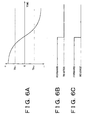
- Fig. 6A is a timing chart illustrating another example of the actual wheel rotating speed. Dotted lines shown in Fig. 6A indicate a threshold value TH2 in the case of reverse rotation of the wheel and the threshold value TH1 in the case of forward rotation of the wheel. The absolute value of the threshold value TH1 is the same as that of the threshold value TH2.
- Fig. 6B is a timing chart illustrating pulse information of the wheel rotating direction which has just been separated from the pulse information of the wheel rotating speed in step S1 executed by the control routine shown in Fig. 4.
- Fig. 6C is a timing chart illustrating the information of the wheel rotating direction that has been processed in steps S3 to S6 shown in Fig. 4 and output from the signal input portion 10a.
- the ABS computer 10b operates in a selected one of four modes, that is, normal braking mode, pressure-decreasing mode, pressure-keeping mode, and pressure-increasing mode, on the basis of pieces of information with respect to the wheel rotating speed and the wheel rotating direction as obtained from the signal input portion 10a.
- the operation of the ABS computer 10b in the respective operating modes will be briefly described.
- the normal braking mode as a control signal from the ABS computer 10b is not sent to the actuator 34, the fluid pressure corresponding to the displacement of the brake pedal 30 is exerted to the respective wheel cylinders 36, 38, 40, 42 provided in the wheels 12, 14, 16, 18.
- the hydraulic pressure of any one of the wheel cylinders 36, 38, 40, 42 corresponding to the slipping wheel is decreased at a constant rate.
- the hydraulic pressure of any one of the wheel cylinders 36, 38, 40, 42 corresponding to the slipping wheel is kept to be lower than a level corresponding to a displacement of the brake pedal 30, by a predetermined pressure-decreasing amount.
- the hydraulic pressure of any one of the wheel cylinders 36, 38, 40, 42 corresponding to the wheel that has stopped slipping is kept higher than the level established in the holding mode by a predetermined pressure increase amount in accordance with the displacement of the brake pedal 30.
- the ABS control is executed by selecting an appropriate one of the aforementioned modes so as to allow safe and quick braking during vehicle operation.
- the TC computer 10c detects racing of the driving wheel using the information received from the signal input portion 10a, and the information representing the engine speed of the internal combustion engine (not shown). As a result, the racing of the driving wheel can be effectively prevented by controlling the throttle valve of the engine, and operation of the actuator 34.
- the VSC computer 10d detects a possibility of spin or drift of the vehicle during cornering using the information received from the signal input portion 10a or the yaw rate sensor 11, and holds the vehicle in a stable state by controlling the operation of the actuator 34 and the like.
- the signal input portion 10a accurately detects the wheel rotating speed and the wheel rotating direction of the respective wheels 12, 14, 16, 18. Therefore, the ABS control, TC control, and VSC control can be appropriately performed by the respective computers 10b, 10c, 10d. If the calculated result of the wheel rotating speed becomes equal to or greater than a predetermined value, the change in the output of the rotating direction is inhibited. Therefore, an error in the result of detection of the rotation detecting device owing to such factors as the external magnetic field may not occur in any of the wheels 12, 14, 16, 18 during forward or reverse rotating operation. The operating failure in various devices installed in the vehicle, thus, may reliably be prevented.
- the ECU 10 is functionally divided into the signal input portion 10a, ABS computer 10b, TC computer 10c and VSC computer 10d. However, it is also possible to combine those functions into a single computing device.
- the rotating state detecting device of the invention if the wheel rotating speed is equal to or greater than a predetermined value, a change in the output representing the rotating direction is inhibited. Therefore, output failure of the rotating direction can be prevented, resulting in accurate operation of the on-board system.
Landscapes
- Engineering & Computer Science (AREA)
- Transportation (AREA)
- Mechanical Engineering (AREA)
- Regulating Braking Force (AREA)
- Indicating Or Recording The Presence, Absence, Or Direction Of Movement (AREA)
Abstract
Description
Claims (9)
- A vehicle wheel rotation detecting system, comprising:a rotating member (20a, 22a, 24a, 26a) that rotates together with a vehicle wheel (12, 14, 16, 18);a detected portion, that is provided in the rotating member,a detector (20b, 22b, 24b, 26b) that generates a signal in response to a passage of the detected portion; anda rotating direction detector that detects a rotating direction of the vehicle wheel in accordance with an output of the detector, the rotating direction being adapted to be used by an on-board system; whereinwhen a rotating speed of the vehicle wheel is equal to or greater than a predetermined value, a change in an output of the rotating direction is inhibited.
- The vehicle wheel rotation detecting system according to claim 1, wherein the detected portion is at least one protrusion comprising a magnetic material
- The vehicle wheel rotation detecting system according to claim 2, wherein a plurality of protrusions as said at least one protrusion are formed at predetermined intervals on an outer periphery of the rotating member (20a, 22a, 24a, 26a).
- The vehicle wheel rotation detecting system according to one of claims 1 to 3, wherein the detector (20b, 22b, 24b, 26b) comprises a pair of elements, and the rotating direction detector detects the rotating direction of the vehicle wheel (12, 14, 16, 18) on the basis of a difference in phases of pulse signals output from the pair of elements.
- The vehicle wheel rotation detecting system according to claim 4, wherein the pair of elements comprise a semiconductor magnetic sensor
- The vehicle wheel rotation detecting system according to one of claims 1 to 5, further comprising a rotating speed detector that detects a rotating speed of the vehicle wheel on the basis of an interval of pulses of the signal generated from the detector
- A vehicle wheel rotation detecting method comprising the steps of:obtaining information of a rotating direction of a vehicle wheel (12, 14, 16, 18) on the basis of a signal generated by a detector in response to a passage of a detected portion, the detected portion mounted on a rotating member that rotates together with the vehicle wheel; andcalculating a rotating speed of the vehicle wheel on the basis of the detected signal; whereinwhen the rotating speed is equal to or greater than a predetermined value, a change in an output of the rotating direction is made invalid, and a previously detected rotating direction is maintained.
- A vehicle wheel rotation detecting method according to claim 7, wherein the rotating direction of the vehicle wheel is detected on the basis of a difference in phases of pulse signals output from a pair of elements that comprise the detector (20b, 22b, 24b, 26b).
- A vehicle wheel rotation detecting method according to claim 7 or 8, wherein the rotating speed of the vehicle wheel is detected on the basis of an interval of pulses of the signal generated from the detector (20b, 22b, 24b, 26b)
Applications Claiming Priority (2)
| Application Number | Priority Date | Filing Date | Title |
|---|---|---|---|
| JP2000300190 | 2000-09-29 | ||
| JP2000300190A JP2002107371A (en) | 2000-09-29 | 2000-09-29 | Wheel rotation state detector |
Publications (3)
| Publication Number | Publication Date |
|---|---|
| EP1193150A2 true EP1193150A2 (en) | 2002-04-03 |
| EP1193150A3 EP1193150A3 (en) | 2003-08-13 |
| EP1193150B1 EP1193150B1 (en) | 2005-12-28 |
Family
ID=18781905
Family Applications (1)
| Application Number | Title | Priority Date | Filing Date |
|---|---|---|---|
| EP01123482A Expired - Lifetime EP1193150B1 (en) | 2000-09-29 | 2001-09-28 | Vehicle wheel rotation detecting system and method |
Country Status (4)
| Country | Link |
|---|---|
| US (1) | US6559634B2 (en) |
| EP (1) | EP1193150B1 (en) |
| JP (1) | JP2002107371A (en) |
| DE (1) | DE60116210T2 (en) |
Cited By (1)
| Publication number | Priority date | Publication date | Assignee | Title |
|---|---|---|---|---|
| CN116142161A (en) * | 2023-01-03 | 2023-05-23 | 重庆长安汽车股份有限公司 | Method, device, device and storage medium for visualization of vehicle wheel status |
Families Citing this family (45)
| Publication number | Priority date | Publication date | Assignee | Title |
|---|---|---|---|---|
| US6834218B2 (en) | 2001-11-05 | 2004-12-21 | Ford Global Technologies, Llc | Roll over stability control for an automotive vehicle |
| US7233236B2 (en) * | 2000-09-25 | 2007-06-19 | Ford Global Technologies, Llc | Passive wheel lift identification for an automotive vehicle using operating input torque to wheel |
| US7132937B2 (en) * | 2000-09-25 | 2006-11-07 | Ford Global Technologies, Llc | Wheel lift identification for an automotive vehicle using passive and active detection |
| US6904350B2 (en) | 2000-09-25 | 2005-06-07 | Ford Global Technologies, Llc | System for dynamically determining the wheel grounding and wheel lifting conditions and their applications in roll stability control |
| US7109856B2 (en) * | 2000-09-25 | 2006-09-19 | Ford Global Technologies, Llc | Wheel lifted and grounded identification for an automotive vehicle |
| US6356188B1 (en) | 2000-09-25 | 2002-03-12 | Ford Global Technologies, Inc. | Wheel lift identification for an automotive vehicle |
| US6654674B2 (en) | 2001-11-21 | 2003-11-25 | Ford Global Technologies, Llc | Enhanced system for yaw stability control system to include roll stability control function |
| US6556908B1 (en) | 2002-03-04 | 2003-04-29 | Ford Global Technologies, Inc. | Attitude sensing system for an automotive vehicle relative to the road |
| US7085639B2 (en) * | 2002-08-01 | 2006-08-01 | Ford Global Technologies, Llc | System and method for characterizing the road bank for vehicle roll stability control |
| US7194351B2 (en) * | 2002-08-01 | 2007-03-20 | Ford Global Technologies, Llc | System and method for determining a wheel departure angle for a rollover control system |
| US6941205B2 (en) * | 2002-08-01 | 2005-09-06 | Ford Global Technologies, Llc. | System and method for deteching roll rate sensor fault |
| US7003389B2 (en) | 2002-08-01 | 2006-02-21 | Ford Global Technologies, Llc | System and method for characterizing vehicle body to road angle for vehicle roll stability control |
| US7302331B2 (en) * | 2002-08-01 | 2007-11-27 | Ford Global Technologies, Inc. | Wheel lift identification for an automotive vehicle |
| US7079928B2 (en) * | 2002-08-01 | 2006-07-18 | Ford Global Technologies, Llc | System and method for determining a wheel departure angle for a rollover control system with respect to road roll rate and loading misalignment |
| US20040024504A1 (en) * | 2002-08-05 | 2004-02-05 | Salib Albert Chenouda | System and method for operating a rollover control system during an elevated condition |
| US7085642B2 (en) * | 2002-08-05 | 2006-08-01 | Ford Global Technologies, Llc | Method and system for correcting sensor offsets |
| US6963797B2 (en) | 2002-08-05 | 2005-11-08 | Ford Global Technologies, Llc | System and method for determining an amount of control for operating a rollover control system |
| US6961648B2 (en) * | 2002-08-05 | 2005-11-01 | Ford Motor Company | System and method for desensitizing the activation criteria of a rollover control system |
| US7430468B2 (en) * | 2002-08-05 | 2008-09-30 | Ford Global Technologies, Llc | System and method for sensitizing the activation criteria of a rollover control system |
| US20040024505A1 (en) | 2002-08-05 | 2004-02-05 | Salib Albert Chenouda | System and method for operating a rollover control system in a transition to a rollover condition |
| US7653471B2 (en) * | 2003-02-26 | 2010-01-26 | Ford Global Technologies, Llc | Active driven wheel lift identification for an automotive vehicle |
| US7239949B2 (en) | 2003-02-26 | 2007-07-03 | Ford Global Technologies, Llc | Integrated sensing system |
| US9162656B2 (en) * | 2003-02-26 | 2015-10-20 | Ford Global Technologies, Llc | Active driven wheel lift identification for an automotive vehicle |
| US7136731B2 (en) * | 2003-06-11 | 2006-11-14 | Ford Global Technologies, Llc | System for determining vehicular relative roll angle during a potential rollover event |
| US7308350B2 (en) * | 2004-05-20 | 2007-12-11 | Ford Global Technologies, Llc | Method and apparatus for determining adaptive brake gain parameters for use in a safety system of an automotive vehicle |
| US7451032B2 (en) | 2004-06-02 | 2008-11-11 | Ford Global Technologies, Llc | System and method for determining desired yaw rate and lateral velocity for use in a vehicle dynamic control system |
| US7640081B2 (en) * | 2004-10-01 | 2009-12-29 | Ford Global Technologies, Llc | Roll stability control using four-wheel drive |
| US7715965B2 (en) | 2004-10-15 | 2010-05-11 | Ford Global Technologies | System and method for qualitatively determining vehicle loading conditions |
| US7668645B2 (en) | 2004-10-15 | 2010-02-23 | Ford Global Technologies | System and method for dynamically determining vehicle loading and vertical loading distance for use in a vehicle dynamic control system |
| US7660654B2 (en) | 2004-12-13 | 2010-02-09 | Ford Global Technologies, Llc | System for dynamically determining vehicle rear/trunk loading for use in a vehicle control system |
| DE102005016110A1 (en) * | 2005-04-08 | 2006-10-12 | GM Global Technology Operations, Inc., Detroit | Roll direction determination method for motor vehicle, involves assigning phase shift to rotation signals from rotation sensors in first roll direction and changing phase shift in roll direction opposite first roll direction |
| US7480547B2 (en) | 2005-04-14 | 2009-01-20 | Ford Global Technologies, Llc | Attitude sensing system for an automotive vehicle relative to the road |
| US7590481B2 (en) | 2005-09-19 | 2009-09-15 | Ford Global Technologies, Llc | Integrated vehicle control system using dynamically determined vehicle conditions |
| US7600826B2 (en) | 2005-11-09 | 2009-10-13 | Ford Global Technologies, Llc | System for dynamically determining axle loadings of a moving vehicle using integrated sensing system and its application in vehicle dynamics controls |
| US8121758B2 (en) | 2005-11-09 | 2012-02-21 | Ford Global Technologies | System for determining torque and tire forces using integrated sensing system |
| JP2007170922A (en) * | 2005-12-20 | 2007-07-05 | Denso Corp | Rotation detection device signal processing circuit |
| DE102006020490A1 (en) * | 2006-02-24 | 2007-08-30 | Volkswagen Ag | Method and device for determining the circumference of vehicle wheels |
| GB2454223B (en) * | 2007-11-01 | 2011-09-21 | Haldex Brake Products Ltd | Vehicle stability control method |
| US10017015B2 (en) | 2011-09-30 | 2018-07-10 | Infineon Technologies Ag | Method for detecting wheel rotation using a one-dimensional acceleration sensor |
| US8700286B2 (en) | 2011-12-21 | 2014-04-15 | Infineon Technologies Ag | Tire localization systems and methods in tire pressure monitoring systems |
| JP5956794B2 (en) * | 2012-03-19 | 2016-07-27 | 日立オートモティブシステムズ株式会社 | Control device for internal combustion engine |
| US8965691B1 (en) * | 2012-10-05 | 2015-02-24 | Google Inc. | Position and direction determination using multiple single-channel encoders |
| DE102013216143B4 (en) * | 2013-08-14 | 2022-12-29 | Zf Friedrichshafen Ag | Process and control unit for generating a combined speed/direction signal |
| DE102018001053A1 (en) * | 2018-02-09 | 2019-08-14 | Knorr-Bremse Systeme für Nutzfahrzeuge GmbH | Method and device for determining a speed with the aid of an inductive speed sensor |
| EP3872529B1 (en) * | 2020-02-28 | 2025-03-26 | STMicroelectronics (Grenoble 2) SAS | Speed measurements |
Family Cites Families (12)
| Publication number | Priority date | Publication date | Assignee | Title |
|---|---|---|---|---|
| US3916326A (en) * | 1974-01-31 | 1975-10-28 | Reliance Electric Co | Sensing circuit including polarity discriminator |
| JPS59210374A (en) * | 1983-05-16 | 1984-11-29 | Nissan Motor Co Ltd | Wheel speed arithmetic device |
| US4629982A (en) * | 1983-07-01 | 1986-12-16 | Transducer Systems, Inc. | Apparatus for detecting motion and direction using magnetoresistive sensors producing sum and difference signals |
| US4836616A (en) * | 1986-01-31 | 1989-06-06 | Rockwell International Corporation | Antilock brake system |
| JPH01114759A (en) * | 1987-10-28 | 1989-05-08 | Nippon Soken Inc | Displacement speed detector |
| US5251968A (en) * | 1989-07-19 | 1993-10-12 | Lucas Industries Public Limited Company | Braking apparatus for a two-axle vehicle |
| KR100194354B1 (en) * | 1995-07-28 | 1999-06-15 | 전주범 | Motion recorder of anti-lock brake system |
| DE19621902A1 (en) * | 1996-05-31 | 1997-12-04 | Bosch Gmbh Robert | Information overlay system |
| JPH1164363A (en) * | 1997-08-25 | 1999-03-05 | Aisin Seiki Co Ltd | Rotation detector |
| JP2000187039A (en) | 1998-12-24 | 2000-07-04 | Honda Motor Co Ltd | Rotation detection device |
| JP4964358B2 (en) * | 1999-12-07 | 2012-06-27 | 株式会社デンソー | Rotation sensor detection signal processing apparatus and rotation sensor detection signal output method |
| JP2002104149A (en) * | 2000-09-29 | 2002-04-10 | Toyota Motor Corp | Wheel rotation state detector |
-
2000
- 2000-09-29 JP JP2000300190A patent/JP2002107371A/en active Pending
-
2001
- 2001-09-21 US US09/956,957 patent/US6559634B2/en not_active Expired - Lifetime
- 2001-09-28 DE DE60116210T patent/DE60116210T2/en not_active Expired - Lifetime
- 2001-09-28 EP EP01123482A patent/EP1193150B1/en not_active Expired - Lifetime
Cited By (1)
| Publication number | Priority date | Publication date | Assignee | Title |
|---|---|---|---|---|
| CN116142161A (en) * | 2023-01-03 | 2023-05-23 | 重庆长安汽车股份有限公司 | Method, device, device and storage medium for visualization of vehicle wheel status |
Also Published As
| Publication number | Publication date |
|---|---|
| EP1193150A3 (en) | 2003-08-13 |
| DE60116210D1 (en) | 2006-02-02 |
| JP2002107371A (en) | 2002-04-10 |
| EP1193150B1 (en) | 2005-12-28 |
| DE60116210T2 (en) | 2006-08-31 |
| US20020041182A1 (en) | 2002-04-11 |
| US6559634B2 (en) | 2003-05-06 |
Similar Documents
| Publication | Publication Date | Title |
|---|---|---|
| EP1193150B1 (en) | Vehicle wheel rotation detecting system and method | |
| US6747553B2 (en) | Apparatus for detecting rotational state of wheel | |
| US5345385A (en) | Method for detecting driving situation with respect to vehicle yaw behavior | |
| US6035693A (en) | System for detecting abnormality of yaw rate sensor and lateral acceleration sensor | |
| JP3289474B2 (en) | Vehicle control device | |
| CN102770771A (en) | Acceleration/deceleration detection system | |
| US6266599B1 (en) | Method and device for adjusting an amount of movement representing the vehicle motion | |
| JP2708021B2 (en) | Vehicle straight traveling state determination device | |
| KR960003120B1 (en) | Controlling method for an antiskid brake system | |
| JP2928890B2 (en) | Acceleration sensor abnormality detection device of anti-skid control device with acceleration sensor | |
| KR100358738B1 (en) | Method for calculating the body speed of a four-wheel drive antilock brake system | |
| JP3188323B2 (en) | Body speed estimation device | |
| JP2000344087A (en) | Wheel speed abnormality detection device | |
| EP2208651B1 (en) | Acceleration vector controlled vehicle cornering stability system | |
| JP2008273280A (en) | Accelerated slip detection device for four-wheel drive vehicles | |
| JP4258162B2 (en) | Method for determining operation of antilock brake system in brake control device, brake control device, four-wheel drive vehicle, program, recording medium | |
| JPH04244463A (en) | Estimating method for car body speed of automobile | |
| JPH08178786A (en) | Pressure sensor abnormality detection device | |
| JP2001074772A (en) | Body acceleration calculation device | |
| KR101078251B1 (en) | Control method of vehicles' stability | |
| JP2520114B2 (en) | Pseudo vehicle speed calculation device for anti-skidding control device | |
| JP3893875B2 (en) | Anti-skid control device for four-wheel drive vehicle | |
| JP2000055932A (en) | Abnormality detection device for vehicle running state detection sensor | |
| JP2003165432A (en) | Vehicle speed detection device | |
| CN120225407A (en) | Method and system for assisting braking of a vehicle |
Legal Events
| Date | Code | Title | Description |
|---|---|---|---|
| PUAI | Public reference made under article 153(3) epc to a published international application that has entered the european phase |
Free format text: ORIGINAL CODE: 0009012 |
|
| 17P | Request for examination filed |
Effective date: 20011019 |
|
| AK | Designated contracting states |
Kind code of ref document: A2 Designated state(s): AT BE CH CY DE DK ES FI FR GB GR IE IT LI LU MC NL PT SE TR |
|
| AX | Request for extension of the european patent |
Free format text: AL;LT;LV;MK;RO;SI |
|
| PUAL | Search report despatched |
Free format text: ORIGINAL CODE: 0009013 |
|
| AK | Designated contracting states |
Designated state(s): AT BE CH CY DE DK ES FI FR GB GR IE IT LI LU MC NL PT SE TR |
|
| AX | Request for extension of the european patent |
Extension state: AL LT LV MK RO SI |
|
| 17Q | First examination report despatched |
Effective date: 20040226 |
|
| AKX | Designation fees paid |
Designated state(s): DE FR GB |
|
| GRAP | Despatch of communication of intention to grant a patent |
Free format text: ORIGINAL CODE: EPIDOSNIGR1 |
|
| GRAS | Grant fee paid |
Free format text: ORIGINAL CODE: EPIDOSNIGR3 |
|
| GRAA | (expected) grant |
Free format text: ORIGINAL CODE: 0009210 |
|
| AK | Designated contracting states |
Kind code of ref document: B1 Designated state(s): DE FR GB |
|
| REG | Reference to a national code |
Ref country code: GB Ref legal event code: FG4D |
|
| REF | Corresponds to: |
Ref document number: 60116210 Country of ref document: DE Date of ref document: 20060202 Kind code of ref document: P |
|
| ET | Fr: translation filed | ||
| PLBE | No opposition filed within time limit |
Free format text: ORIGINAL CODE: 0009261 |
|
| STAA | Information on the status of an ep patent application or granted ep patent |
Free format text: STATUS: NO OPPOSITION FILED WITHIN TIME LIMIT |
|
| 26N | No opposition filed |
Effective date: 20060929 |
|
| REG | Reference to a national code |
Ref country code: GB Ref legal event code: 746 Effective date: 20091103 |
|
| REG | Reference to a national code |
Ref country code: FR Ref legal event code: PLFP Year of fee payment: 15 |
|
| PGFP | Annual fee paid to national office [announced via postgrant information from national office to epo] |
Ref country code: GB Payment date: 20150923 Year of fee payment: 15 |
|
| PGFP | Annual fee paid to national office [announced via postgrant information from national office to epo] |
Ref country code: FR Payment date: 20150629 Year of fee payment: 15 |
|
| GBPC | Gb: european patent ceased through non-payment of renewal fee |
Effective date: 20160928 |
|
| REG | Reference to a national code |
Ref country code: FR Ref legal event code: ST Effective date: 20170531 |
|
| PG25 | Lapsed in a contracting state [announced via postgrant information from national office to epo] |
Ref country code: GB Free format text: LAPSE BECAUSE OF NON-PAYMENT OF DUE FEES Effective date: 20160928 Ref country code: FR Free format text: LAPSE BECAUSE OF NON-PAYMENT OF DUE FEES Effective date: 20160930 |
|
| PGFP | Annual fee paid to national office [announced via postgrant information from national office to epo] |
Ref country code: DE Payment date: 20200916 Year of fee payment: 20 |
|
| REG | Reference to a national code |
Ref country code: DE Ref legal event code: R071 Ref document number: 60116210 Country of ref document: DE |