EP1193139A2 - Air bag apparatus for a motor vehicle - Google Patents
Air bag apparatus for a motor vehicle Download PDFInfo
- Publication number
- EP1193139A2 EP1193139A2 EP01308346A EP01308346A EP1193139A2 EP 1193139 A2 EP1193139 A2 EP 1193139A2 EP 01308346 A EP01308346 A EP 01308346A EP 01308346 A EP01308346 A EP 01308346A EP 1193139 A2 EP1193139 A2 EP 1193139A2
- Authority
- EP
- European Patent Office
- Prior art keywords
- air bag
- belt
- introduction port
- gas introduction
- front side
- Prior art date
- Legal status (The legal status is an assumption and is not a legal conclusion. Google has not performed a legal analysis and makes no representation as to the accuracy of the status listed.)
- Granted
Links
Images


Classifications
-
- B—PERFORMING OPERATIONS; TRANSPORTING
- B60—VEHICLES IN GENERAL
- B60R—VEHICLES, VEHICLE FITTINGS, OR VEHICLE PARTS, NOT OTHERWISE PROVIDED FOR
- B60R21/00—Arrangements or fittings on vehicles for protecting or preventing injuries to occupants or pedestrians in case of accidents or other traffic risks
- B60R21/02—Occupant safety arrangements or fittings, e.g. crash pads
- B60R21/16—Inflatable occupant restraints or confinements designed to inflate upon impact or impending impact, e.g. air bags
- B60R21/23—Inflatable members
- B60R21/231—Inflatable members characterised by their shape, construction or spatial configuration
- B60R21/233—Inflatable members characterised by their shape, construction or spatial configuration comprising a plurality of individual compartments; comprising two or more bag-like members, one within the other
-
- B—PERFORMING OPERATIONS; TRANSPORTING
- B60—VEHICLES IN GENERAL
- B60R—VEHICLES, VEHICLE FITTINGS, OR VEHICLE PARTS, NOT OTHERWISE PROVIDED FOR
- B60R21/00—Arrangements or fittings on vehicles for protecting or preventing injuries to occupants or pedestrians in case of accidents or other traffic risks
- B60R21/02—Occupant safety arrangements or fittings, e.g. crash pads
- B60R21/16—Inflatable occupant restraints or confinements designed to inflate upon impact or impending impact, e.g. air bags
- B60R21/23—Inflatable members
- B60R21/231—Inflatable members characterised by their shape, construction or spatial configuration
- B60R21/2334—Expansion control features
- B60R21/2338—Tethers
- B60R2021/23382—Internal tether means
Definitions
- the present invention relates to an air bag apparatus of a vehicle, and more particularly to an air bag apparatus for a front passenger.
- An air bag apparatus for a front passenger of the motor vehicle is structured such that an air bag is received in a folded state in an instrument panel positioned below of a front window panel.
- the air bag is structured such as to expand due to a gas injected out from an inflator at a time of collision, develop toward an inner side of a passenger's room from an upper portion of the instrument panel and receive the passenger falling forward so as to protect the passenger.
- a tether belt extending in a longitudinal direction from a gas introduction port of an air bag to a portion close to a rear end is provided in an inner portion of the air bag used in this kind of air bag apparatus, for example, as is known in Japanese Patent Application Laid-open No. 11-5505.
- the tether belt has a function of guiding a gas stream output from the gas introduction port to the rear end side of the air bag in an initial expanding state of the air bag, and a function of restricting a linear development of the air bag to an inner side of the passenger's room and developing so as to extend in a vertical direction.
- the tether belt is long and the rear end of the tether belt is positioned in the passenger compartment disposed beyond the rear end of the instrument panel in the initial expanding state of the air bag. Accordingly, in the case of a normal state in which the front passenger existing in the front passenger's seat is sufficiently apart from the instrument panel, the air bag in the initial expanding state expands upward and downward with being restricted to develop rearward by the tether belt before reaching to the passenger mentioned above, however, in the case that the passenger is much close to the instrument panel, the rear end of the air bag is brought into contact with the passenger before expanding upward and downward at a stage of the initial expansion, so that there is a risk that an excessive impact is applied to the passenger.
- the present invention has been made in consideration of the prior art mentioned above, and an object of the present invention is to provide an air bag apparatus for a motor vehicle which can securely protect a passenger even in an approaching state without significantly increasing a cost.
- an air bag for a vehicle having a front portion including a gas introduction port introducing an inflation gas therethrough wherein the air bag is placed at a predetermined position of the vehicle interior with respect to the gas introduction port and develops rearward due to a motivation, a tether belt connecting the gas introduction port and a rear portion at an upper side of the air bag, wherein a rear end portion of the tether belt extending in an initial developing stage of the air bag toward a vertical surface passing a rear end of an instrument panel of the vehicle is positioned in the surface.
- a length of the tether belt is equal to or less than a horizontal distance between the gas introduction port and the vertical surface.
- a front end of the tether belt is connected to a rear edge of the gas introduction port.
- the rear end of the tether belt is connected to a portion forming an upper surface portion of the air bag.
- the tether belt is provided with a front side belt a front end of which is connected to the gas introduction port, and a rear side belt connected to another end of the front side belt and having a middle portion connected to an upper side of the air bag so as to constitute a patch portion having a predetermined area and two end portions both connected to another end of the front side belt.
- the tether belt is provided with a front side belt having two end portions and a middle portion of which is connected to the gas introduction port so as to constitute a patch portion having a predetermined area, and a rear side belt connected to another end of the front side belt and having a middle portion connected to an upper side of the air bag so as to constitute a patch portion and two end portions both connected to both ends of the front side belt. Accordingly, since the front side belt is also constituted by a two-sheet structure, a strength of the tether belt is improved, and the gas introduction port is reinforced by the patch portion of the front side belt.
- the air bag is formed in a bag shape by connecting a lower base fabric and an upper base fabric, the gas introduction port is provided in a front portion of the lower base fabric, one end of the tether belt is connected to the upper base fabric, the tether belt has one front side belt in which a front end of the lower base fabric is connected to the gas introduction port and a rear side belt a middle portion of which is connected to the upper base fabric so as to constitute a patch portion having a predetermined area, and both end portions of the rear side belt are connected to a rear end of the front side belt.
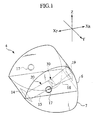
- Figs. 1 to 8 are views showing a first embodiment according to the present invention.
- an instrument panel 2 is positioned below a front window panel 1 in an assistant driver's seat side of a motor vehicle.
- a case 3 closed by a lid is provided in an upper portion of the instrument panel 2, and an air bag 4 in a folded state and an inflator 5 injecting a gas for inflating the bag are received within the case 3.
- the air bag 4 is constituted by two fabrics such as upper base fabric 6 and a lower base fabric 7 which are made of non-coated nylon 66 woven cloth having a weight (weight per area) of 200 g/m 2 .
- the upper base fabric 6 and the lower base fabric 7 are, as shown in Figs. 2 and 3, both formed in a symmetrical shape, the upper base fabric 6 has an upper portion 8 forming an upper surface portion of the expanding air bag 4, and the lower base fabric 7 has a lower portion 9 forming a lower surface portion of the expanding air bag 4.
- Substantially triangular side portions 10 and 11 forming side surface portions of the expanding air bag 4 are formed in both right and left sides of the upper portion 8 in the upper base fabric 6 and the lower portion 9 in the lower base fabric 7, and rear portions 12 and 13 forming a rear surface portion receiving a passenger are integrally provided in rear sides thereof.
- a rectangular gas introduction port 14 is formed in a front end of the lower base fabric 7, a front end 16 of a front side belt 15 having the same opening as the gas introduction port 14 is superposed and sewed up in the periphery of the gas introduction port 14, and a main body of the front side belt 15 is in a state of extending toward a rear side from a rear edge of the gas introduction port 14.
- the gas introduction port 14 is reinforced by sewing up the front end 16 of the front side belt 15 in the periphery thereof.
- a vent hole 17 is formed in each of the left and right side portions 10 in the upper base fabric 6.
- the vent hole 17 is provided so as to release an extra gas at a time when the air bag 4 is completely expanded.
- a peripheral edge of a patch portion 19 having a rectangular shape or a circular shape with a vertical width of 150 mm and a lateral width of 160 mm is sewed up in a center portion 18c of a rear side belt 18 in the rear portion 12 of the upper base fabric 6.
- the rear side belt is structured such as to be provided with an upper band portion 18a and a lower band portion 18b.
- the rear side belt 18 may be constituted by a plurality of members.
- the corresponding side portions 10 and 11 and the edge portions of the rear portions 12 and 13 are sewed up with each other in a state of facing back surfaces in which the front side belt 15 and the rear side belt 18 are positioned in a front surface side to each other.
- the opposing peripheral edge portions of the lower base fabric 7 and the upper base fabric 6 are sewed up with each other. Then, as shown in Fig.
- the lower base fabric 7 and the upper base fabric 6 which are sewed up with each other are bent, the front side belt 15 and the rear side belt 18 are moved close to each other, and the rear end of the front side belt 15 and both ends of the rear side belt 18 which are positioned in back and front sides in this state are sewed up, whereby a tether belt 20 is formed.
- the tether belt 20 is positioned in an inner portion and the air bag 4 in which a peripheral seam is invisible is completed.
- the completed air bag 4 becomes in a state that the gas introduction port 14 at the front portion of the lower base fabric 7 and the rear portion 12 of the upper base fabric 6 are connected therewithin by the tether belt 20.
- the air bag 4 formed in the manner mentioned above is received within the case 3 in the upper portion of the instrument panel 2 in a state of being folded as mentioned above, and the gas introduction port 14 is connected to the inflator 5.
- a length of the tether belt 20 provided in the inner portion of the air bag 4 is shorter than the conventional one, and if the tether belt 20 is horizontally extended to a rear side in a static state in a state of being assembled in the instrument panel 2, the structure is made such that a rear end (a patch portion 19) substantially coincides with a vertical surface A passing through a rear end 21 of the instrument panel 2. Otherwise, the rear end may be disposed in front of the vertical surface A . That is, one feature of the present invention is that the air bag is developed so that the expanding surface of the air bag does not directly hit a passenger at an initial expanding stage of the air bag.
- Fig. 5 shows a state that a passenger M stands close to the instrument panel 2.
- the impact force is detected so as to motivate an operation of the air bag.
- the gas generated in the inflator 5 is discharged within the air bag 4 from the gas introduction port 14, and the air bag 4 is expanded. Since the front side belt 15 of the tether belt 20 extends from the rear edge of the gas introduction port 14, the gas introduction port 14 is not closed by the front side belt 15, a smooth inflow of the gas from the gas introduction port 14 is executed and a developing speed of the air bag 4 becomes faster.
- the expanding air bag 4 jumps out from the case 3 as shown in Fig. 6, then the air bag is brought into contact with a part 31 of a front window panel 1 and thereafter develops rearward as an initial expansion due to a jet flow F1.
- the length of the tether belt 20 within the air bag 4 is defined as a length just reaching the vertical surface A passing through the rear end 21 of the instrument panel 2. Accordingly, the tether belt 20 tends to extend at an upward angle in the initial expanding state, and the rear end of the tether belt 20 does not exceed the vertical surface A .
- the rear side belt is structured such that the upper band portion 18a, the lower band portion 18b and the patch portion 19 form a substantially triangular tube structure around a sewing portion 30 corresponding to a supporting point, and a distance from a rear edge portion 33 of the gas introduction port 14 is defined together with the front side belt 15, therefore it is possible to restrict a rearward protrusion of a whole of the patch portion at the initial expanding stage.
- a gas stream (localized pressure) passing through a portion near a surface of the upper band portion 18a and the lower band portion 18b assists an orientation change of the triangular tube structure together with the support at the contact surface 31 between the front window panel 1 and the upper base fabric 6, thereby the surface of the patch portion 19 is securely directed rearward due to a rotating function performed by the air bag 4 of the present embodiment.
- a downward force applied by the gas stream passing though the upper side of the upper band portion 18a has an effect of modifying an attitude of the tether belt having a tendency of extending at an upward angle in the initial expanding state.
- the rear end of the tether belt 20 is connected to the upper base fabric 6 so as to constitute the patch portion 19 having a predetermined area, a bonding force between the tether belt 20 and the upper base fabric 6 is strong, thereby sufficiently receiving the impact force applied at a time when the patch portion 19 reaches the portion near the vertical surface A , therefore it is possible to securely restrict the rearward development of the air bag 4. Further, since the tether belt 20 is inexpensive, it is possible to significantly reduce a manufacturing cost.
- the air bag 4 develops downward as shown in Fig. 7 after the initial expansion due to additional supply of gas from the inflator in such a way that the air bag enters between the instrument panel 2 and the passenger M.
- the air bag 4 develops downward because the rear end of the tether belt 20 is connected to the upper base fabric 6 of the air bag 4, a lower capacity of the tether belt 20 is larger than an upper capacity at the rear end of the air bag 4, and the gas flow received by the patch portion 19 and/or the center portion 18c of the rear side belt 18 in the first stage is changed downward whereby the portion below the tether belt 20 mainly expands.
- the air bag 4 develops upward as shown in Fig. 8 after developing downward according to additional supply of gas from the inflator, and it is possible to securely protect both of a head portion and a body portion of the passenger M. Since the tether belt 20 according to this embodiment is connected to the gas introduction port 14 via one front side belt 15, a tension applied to the upper base fabric 6 of the air bag 4 from the tether belt 20 is transmitted on the basis of one system, so that it is possible to obtain a stable developing motion of the air bag 4.
- vent holes 17 are formed in the side portions 10 and 11 except the area receiving the passenger, there is no risk that the vent holes 17 are closed by the passenger.
- the tether belt 20 itself does not extend rearward from the vertical surface A , however, the air bag 4 at the lower portion than the tether belt 20 develops sufficiently rearward than the vertical surface A , and it is possible to securely protect the passenger M at a normal position who does not stands close to the instrument panel 2 by the air bag 4.
- the rear end of the tether belt since the rear end of the tether belt is positioned at the vertical surface passing through the rear end of the instrument panel or in front thereof, in the initial expanding state of the air bag, the rearward development of the air bag is restricted just before the passenger due to the tension of the tether belt even in the case that the passenger stands close to the instrument panel, and no excessive impact is applied to the passenger. That is, it is possible to execute by the inexpensive means. Since the rear end of the tether belt is connected to the upper side of the air bag, the air bag develops in a direction of expanding downward after the initial expansion, and it is possible to securely receive the head portion and the body portion of the passenger so as to protect them.
- Figs. 9 and 10 are views showing a second embodiment according to the present invention.
- a front side belt 23 also forms a patch portion 24 having an opening corresponding to the gas introduction port 14 in a center portion thereof, and the patch portion 24 is sewed up in the periphery of the gas introduction port 14.
- the gas introduction port 14 is reinforced by sewing up the patch portion 24 in the periphery thereof, so as to securely prevent the gas introduction port 14 from being broken due to impact of the gas caused by jet flow from the inflator. Further, both ends of the front side belt 23 and the rear side belt 18 are connected to each other.
- the front side belt 23 is also made in a two-sheet structure, and strength of the tether belt 22 is improved.
- both of the front side belt 23 and the rear side belt 18 are made in a two-sheet structure, they are sewed up as a one-sheet member obtained by overlapping both ends with each other and have flexibility for bending in a vertical direction (Z), thereby the tension is transmitted by the tether belt 22 on the basis of substantially one system, as a result, a stable developing motion of the air bag can be obtained.
- the front side belt 23 extending from the front edge of the gas introduction port 14 extends in a direction of closing the gas introduction port 14, however, both right and left sides of the gas introduction port 14 are open, and there is no problem in view of an inflow performance of the gas.
- Figs. 11 and 12 are views showing a third embodiment according to the present invention.
- the structure is made such that the patch portion 19 of the rear side belt 18 is connected to the upper portion 8 of the upper base fabric 6.
- the patch portion 19 corresponding to the rear end of the tether belt 20 is connected to the upper portion 8 of the upper base fabric 6, and an operation at the initial expanding time is the same as that of the case of the preceding embodiment, however, the patch portion 19 of the tether belt 20 is in a state of being pressed to the front window panel 1 in a state that the air bag 4 finally expands, then a final state of the air bag 4 becomes more stable.
- the tether belt 20 defines a distance from a rear edge portion 33 of the gas introduction port 14, a contact position 35 with respect to the front window panel 1 is necessarily determined. Furthermore, the rear portion 12 of the upper base fabric 6 and the lower base fabric 7 integrally constitute a shape of the rear portion of the air bag, and then a final shape of the air bag 4 after the third stage becomes stable.
- the rear end of the tether belt is positioned at the vertical surface passing through the rear end of the instrument panel or in front of the vertical surface, in the initial expanding state of the air bag, the rearward development of the air bag is restricted just before the passenger due to the tension of the tether belt even in the case that the passenger stands close to the instrument panel, and the means for preventing the excessive impact from being applied to the passenger can be made significantly inexpensive. Since the rear end of the tether belt is connected to the upper base fabric of the air bag, the air bag develops in the direction or expanding downward after the initial expansion, thereby it is possible to securely receive the head portion and the body portion of the passenger so as to protect them.
Abstract
Description
- The present invention relates to an air bag apparatus of a vehicle, and more particularly to an air bag apparatus for a front passenger.
- An air bag apparatus for a front passenger of the motor vehicle is structured such that an air bag is received in a folded state in an instrument panel positioned below of a front window panel. The air bag is structured such as to expand due to a gas injected out from an inflator at a time of collision, develop toward an inner side of a passenger's room from an upper portion of the instrument panel and receive the passenger falling forward so as to protect the passenger.
- A tether belt extending in a longitudinal direction from a gas introduction port of an air bag to a portion close to a rear end is provided in an inner portion of the air bag used in this kind of air bag apparatus, for example, as is known in Japanese Patent Application Laid-open No. 11-5505. The tether belt has a function of guiding a gas stream output from the gas introduction port to the rear end side of the air bag in an initial expanding state of the air bag, and a function of restricting a linear development of the air bag to an inner side of the passenger's room and developing so as to extend in a vertical direction.
- However, in the prior art mentioned above, the tether belt is long and the rear end of the tether belt is positioned in the passenger compartment disposed beyond the rear end of the instrument panel in the initial expanding state of the air bag. Accordingly, in the case of a normal state in which the front passenger existing in the front passenger's seat is sufficiently apart from the instrument panel, the air bag in the initial expanding state expands upward and downward with being restricted to develop rearward by the tether belt before reaching to the passenger mentioned above, however, in the case that the passenger is much close to the instrument panel, the rear end of the air bag is brought into contact with the passenger before expanding upward and downward at a stage of the initial expansion, so that there is a risk that an excessive impact is applied to the passenger.
- In order to prevent the excessive impact from being applied to the passenger in the latter state, it is necessary to provide with a rotating mechanism for changing a developing direction of the air bag and a sensor for detecting an approaching state that is out of usual position. Then, the structure is made such that a developing angle of the air bag is changed to a direction in which the excessive impact is not applied to the passenger, at a time of detecting the approaching state by the sensor, however, according to this countermeasure, a cost is significantly increased.
- The present invention has been made in consideration of the prior art mentioned above, and an object of the present invention is to provide an air bag apparatus for a motor vehicle which can securely protect a passenger even in an approaching state without significantly increasing a cost.
- According to a first technical aspect of the present invention, there is provided an air bag for a vehicle having a front portion including a gas introduction port introducing an inflation gas therethrough wherein the air bag is placed at a predetermined position of the vehicle interior with respect to the gas introduction port and develops rearward due to a motivation, a tether belt connecting the gas introduction port and a rear portion at an upper side of the air bag, wherein a rear end portion of the tether belt extending in an initial developing stage of the air bag toward a vertical surface passing a rear end of an instrument panel of the vehicle is positioned in the surface.
- According to a second technical aspect of the present invention, a length of the tether belt is equal to or less than a horizontal distance between the gas introduction port and the vertical surface.
- According to a third technical aspect of the present invention, a front end of the tether belt is connected to a rear edge of the gas introduction port.
- According to a fourth technical aspect of the present invention, the rear end of the tether belt is connected to a portion forming an upper surface portion of the air bag.
- According to a fifth technical aspect of the present invention, the tether belt is provided with a front side belt a front end of which is connected to the gas introduction port, and a rear side belt connected to another end of the front side belt and having a middle portion connected to an upper side of the air bag so as to constitute a patch portion having a predetermined area and two end portions both connected to another end of the front side belt.
- According to a sixth technical aspect of the present invention, the tether belt is provided with a front side belt having two end portions and a middle portion of which is connected to the gas introduction port so as to constitute a patch portion having a predetermined area, and a rear side belt connected to another end of the front side belt and having a middle portion connected to an upper side of the air bag so as to constitute a patch portion and two end portions both connected to both ends of the front side belt. Accordingly, since the front side belt is also constituted by a two-sheet structure, a strength of the tether belt is improved, and the gas introduction port is reinforced by the patch portion of the front side belt.
- According to a seventh technical aspect of the present invention, the air bag is formed in a bag shape by connecting a lower base fabric and an upper base fabric, the gas introduction port is provided in a front portion of the lower base fabric, one end of the tether belt is connected to the upper base fabric, the tether belt has one front side belt in which a front end of the lower base fabric is connected to the gas introduction port and a rear side belt a middle portion of which is connected to the upper base fabric so as to constitute a patch portion having a predetermined area, and both end portions of the rear side belt are connected to a rear end of the front side belt.
-
- Fig. 1 is a perspective view showing an air bag according to a first embodiment of the present invention;
- Fig. 2 is a plan view showing a lower base fabric of the air bag shown in Fig. 1;
- Fig. 3 is a plan view showing an upper base fabric of the air bag shown in Fig. 1;
- Fig. 4 is a perspective view showing a tether belt constituted by a front side belt and a rear side belt shown in Fig. 1;
- Fig. 5 is a side view of a passenger compartment showing a state that a passenger stands close to an instrument panel;
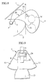
- Fig. 6 is a side view of the passenger compartment showing an initial expanding state of the air bag shown in Fig. 5;
- Fig. 7 is a side view of the passenger compartment showing a state that the air bag shown in Fig. 6 develops downward;
- Fig. 8 is a side view of the passenger compartment showing a final developing state of the air bag shown in Fig. 7;
- Fig. 9 is a plan view showing a lower base fabric according to a second embodiment;
- Fig. 10 is a perspective view showing a tether belt constituted by a front side belt and a rear side belt according to the second embodiment;
- Fig. 11 is a plan view showing an upper base fabric of an air bag according to a third embodiment; and
- Fig. 12 is a side view of a passenger compartment showing a final developing state of the air bag according to the third embodiment.
-
- A description will be given below of preferred embodiments according to the present invention with reference to the accompanying drawings.
- Figs. 1 to 8 are views showing a first embodiment according to the present invention. At first, as shown in Fig. 5, an
instrument panel 2 is positioned below afront window panel 1 in an assistant driver's seat side of a motor vehicle. Acase 3 closed by a lid (not shown) is provided in an upper portion of theinstrument panel 2, and anair bag 4 in a folded state and aninflator 5 injecting a gas for inflating the bag are received within thecase 3. - The
air bag 4 is constituted by two fabrics such asupper base fabric 6 and alower base fabric 7 which are made of non-coated nylon 66 woven cloth having a weight (weight per area) of 200 g/m2. Theupper base fabric 6 and thelower base fabric 7 are, as shown in Figs. 2 and 3, both formed in a symmetrical shape, theupper base fabric 6 has anupper portion 8 forming an upper surface portion of the expandingair bag 4, and thelower base fabric 7 has a lower portion 9 forming a lower surface portion of the expandingair bag 4. Substantiallytriangular side portions air bag 4 are formed in both right and left sides of theupper portion 8 in theupper base fabric 6 and the lower portion 9 in thelower base fabric 7, andrear portions gas introduction port 14 is formed in a front end of thelower base fabric 7, afront end 16 of afront side belt 15 having the same opening as thegas introduction port 14 is superposed and sewed up in the periphery of thegas introduction port 14, and a main body of thefront side belt 15 is in a state of extending toward a rear side from a rear edge of thegas introduction port 14. Thegas introduction port 14 is reinforced by sewing up thefront end 16 of thefront side belt 15 in the periphery thereof. - Further, a
vent hole 17 is formed in each of the left andright side portions 10 in theupper base fabric 6. Thevent hole 17 is provided so as to release an extra gas at a time when theair bag 4 is completely expanded. Further, a peripheral edge of apatch portion 19 having a rectangular shape or a circular shape with a vertical width of 150 mm and a lateral width of 160 mm is sewed up in acenter portion 18c of arear side belt 18 in therear portion 12 of theupper base fabric 6. Accordingly, the rear side belt is structured such as to be provided with anupper band portion 18a and alower band portion 18b. In this case, therear side belt 18 may be constituted by a plurality of members. - In the
lower base fabric 7 and theupper base fabric 6, at first, thecorresponding side portions rear portions front side belt 15 and therear side belt 18 are positioned in a front surface side to each other. Next, the opposing peripheral edge portions of thelower base fabric 7 and theupper base fabric 6 are sewed up with each other. Then, as shown in Fig. 4, thelower base fabric 7 and theupper base fabric 6 which are sewed up with each other are bent, thefront side belt 15 and therear side belt 18 are moved close to each other, and the rear end of thefront side belt 15 and both ends of therear side belt 18 which are positioned in back and front sides in this state are sewed up, whereby atether belt 20 is formed. Finally, when reversing thelower base fabric 7 and theupper base fabric 6 from thegas introduction port 14, thetether belt 20 is positioned in an inner portion and theair bag 4 in which a peripheral seam is invisible is completed. The completedair bag 4 becomes in a state that thegas introduction port 14 at the front portion of thelower base fabric 7 and therear portion 12 of theupper base fabric 6 are connected therewithin by thetether belt 20. - The
air bag 4 formed in the manner mentioned above is received within thecase 3 in the upper portion of theinstrument panel 2 in a state of being folded as mentioned above, and thegas introduction port 14 is connected to theinflator 5. A length of thetether belt 20 provided in the inner portion of theair bag 4 is shorter than the conventional one, and if thetether belt 20 is horizontally extended to a rear side in a static state in a state of being assembled in theinstrument panel 2, the structure is made such that a rear end (a patch portion 19) substantially coincides with a vertical surface A passing through arear end 21 of theinstrument panel 2. Otherwise, the rear end may be disposed in front of the vertical surface A. That is, one feature of the present invention is that the air bag is developed so that the expanding surface of the air bag does not directly hit a passenger at an initial expanding stage of the air bag. - Next, a description will be given of an actual developing motion of the
air bag 4 with reference to Figs. 5 to 8. - Fig. 5 shows a state that a passenger M stands close to the
instrument panel 2. In this state, when an impact force is generated due to a collision, a falling or the like of the motor vehicle, the impact force is detected so as to motivate an operation of the air bag. The gas generated in theinflator 5 is discharged within theair bag 4 from thegas introduction port 14, and theair bag 4 is expanded. Since thefront side belt 15 of thetether belt 20 extends from the rear edge of thegas introduction port 14, thegas introduction port 14 is not closed by thefront side belt 15, a smooth inflow of the gas from thegas introduction port 14 is executed and a developing speed of theair bag 4 becomes faster. - The expanding
air bag 4 jumps out from thecase 3 as shown in Fig. 6, then the air bag is brought into contact with apart 31 of afront window panel 1 and thereafter develops rearward as an initial expansion due to a jet flow F1. At this time, the length of thetether belt 20 within theair bag 4 is defined as a length just reaching the vertical surface A passing through therear end 21 of theinstrument panel 2. Accordingly, thetether belt 20 tends to extend at an upward angle in the initial expanding state, and the rear end of thetether belt 20 does not exceed the vertical surface A. - Additionally, the rear side belt is structured such that the
upper band portion 18a, thelower band portion 18b and thepatch portion 19 form a substantially triangular tube structure around asewing portion 30 corresponding to a supporting point, and a distance from arear edge portion 33 of thegas introduction port 14 is defined together with thefront side belt 15, therefore it is possible to restrict a rearward protrusion of a whole of the patch portion at the initial expanding stage. And a gas stream (localized pressure) passing through a portion near a surface of theupper band portion 18a and thelower band portion 18b assists an orientation change of the triangular tube structure together with the support at thecontact surface 31 between thefront window panel 1 and theupper base fabric 6, thereby the surface of thepatch portion 19 is securely directed rearward due to a rotating function performed by theair bag 4 of the present embodiment. In particular, a downward force applied by the gas stream passing though the upper side of theupper band portion 18a has an effect of modifying an attitude of the tether belt having a tendency of extending at an upward angle in the initial expanding state. - Accordingly, in the case that the passenger M is significantly close to the
instrument panel 2, a rearward development of theair bag 4 is restricted by a position just before the passenger M due to a tension of thetether belt 20 and no excessive impact is applied to the passenger M. Furthermore, since thepatch portion 19 corresponding to a damping surface is securely directed rearward by the rear side belt structure even when the rearward development is restricted, it is possible to stably hold the passenger M. In particular, in this embodiment, since the rear end of thetether belt 20 is connected to theupper base fabric 6 so as to constitute thepatch portion 19 having a predetermined area, a bonding force between thetether belt 20 and theupper base fabric 6 is strong, thereby sufficiently receiving the impact force applied at a time when thepatch portion 19 reaches the portion near the vertical surface A, therefore it is possible to securely restrict the rearward development of theair bag 4. Further, since thetether belt 20 is inexpensive, it is possible to significantly reduce a manufacturing cost. - The
air bag 4 develops downward as shown in Fig. 7 after the initial expansion due to additional supply of gas from the inflator in such a way that the air bag enters between theinstrument panel 2 and the passenger M. In the manner mentioned above, theair bag 4 develops downward because the rear end of thetether belt 20 is connected to theupper base fabric 6 of theair bag 4, a lower capacity of thetether belt 20 is larger than an upper capacity at the rear end of theair bag 4, and the gas flow received by thepatch portion 19 and/or thecenter portion 18c of therear side belt 18 in the first stage is changed downward whereby the portion below thetether belt 20 mainly expands. - The
air bag 4 develops upward as shown in Fig. 8 after developing downward according to additional supply of gas from the inflator, and it is possible to securely protect both of a head portion and a body portion of the passenger M. Since thetether belt 20 according to this embodiment is connected to thegas introduction port 14 via onefront side belt 15, a tension applied to theupper base fabric 6 of theair bag 4 from thetether belt 20 is transmitted on the basis of one system, so that it is possible to obtain a stable developing motion of theair bag 4. That is, if twotether belts 20 are provided and the tension is transmitted to theair bag 4 on the basis of two systems, a mechanical interaction is applied between the tether belts, then the tension transmitted to theair bag 4 becomes unstable in some conditions of twotether belts 20 and there is a risk that theair bag 4 vertically swings and the motion is not uniformly defined. According to the present embodiment, such a problem does not occur in the third stage. - When the
air bag 4 completely expands, a surplus gas is released from the vent holes 17. Since the vent holes 17 are formed in theside portions tether belt 20 itself does not extend rearward from the vertical surface A, however, theair bag 4 at the lower portion than thetether belt 20 develops sufficiently rearward than the vertical surface A, and it is possible to securely protect the passenger M at a normal position who does not stands close to theinstrument panel 2 by theair bag 4. - According to the present embodiment, since the rear end of the tether belt is positioned at the vertical surface passing through the rear end of the instrument panel or in front thereof, in the initial expanding state of the air bag, the rearward development of the air bag is restricted just before the passenger due to the tension of the tether belt even in the case that the passenger stands close to the instrument panel, and no excessive impact is applied to the passenger. That is, it is possible to execute by the inexpensive means. Since the rear end of the tether belt is connected to the upper side of the air bag, the air bag develops in a direction of expanding downward after the initial expansion, and it is possible to securely receive the head portion and the body portion of the passenger so as to protect them.
- Figs. 9 and 10 are views showing a second embodiment according to the present invention. In a
tether belt 22 according to the present embodiment, afront side belt 23 also forms apatch portion 24 having an opening corresponding to thegas introduction port 14 in a center portion thereof, and thepatch portion 24 is sewed up in the periphery of thegas introduction port 14. Thegas introduction port 14 is reinforced by sewing up thepatch portion 24 in the periphery thereof, so as to securely prevent thegas introduction port 14 from being broken due to impact of the gas caused by jet flow from the inflator. Further, both ends of thefront side belt 23 and therear side belt 18 are connected to each other. - According to the second embodiment, the
front side belt 23 is also made in a two-sheet structure, and strength of thetether belt 22 is improved. Although both of thefront side belt 23 and therear side belt 18 are made in a two-sheet structure, they are sewed up as a one-sheet member obtained by overlapping both ends with each other and have flexibility for bending in a vertical direction (Z), thereby the tension is transmitted by thetether belt 22 on the basis of substantially one system, as a result, a stable developing motion of the air bag can be obtained. Thefront side belt 23 extending from the front edge of thegas introduction port 14 extends in a direction of closing thegas introduction port 14, however, both right and left sides of thegas introduction port 14 are open, and there is no problem in view of an inflow performance of the gas. - Figs. 11 and 12 are views showing a third embodiment according to the present invention. According to the present embodiment, the structure is made such that the
patch portion 19 of therear side belt 18 is connected to theupper portion 8 of theupper base fabric 6. According to this third embodiment, thepatch portion 19 corresponding to the rear end of thetether belt 20 is connected to theupper portion 8 of theupper base fabric 6, and an operation at the initial expanding time is the same as that of the case of the preceding embodiment, however, thepatch portion 19 of thetether belt 20 is in a state of being pressed to thefront window panel 1 in a state that theair bag 4 finally expands, then a final state of theair bag 4 becomes more stable. That is, since thetether belt 20 defines a distance from arear edge portion 33 of thegas introduction port 14, acontact position 35 with respect to thefront window panel 1 is necessarily determined. Furthermore, therear portion 12 of theupper base fabric 6 and thelower base fabric 7 integrally constitute a shape of the rear portion of the air bag, and then a final shape of theair bag 4 after the third stage becomes stable. - In all of the embodiments mentioned above, the description is given of the air bag constituted by the two-sheet structure comprising the
upper base fabric 6 and thelower base fabric 7, however, the structure is not limited to this, and the air bag may be constituted by three or more base fabrics. - According to the present invention, since the rear end of the tether belt is positioned at the vertical surface passing through the rear end of the instrument panel or in front of the vertical surface, in the initial expanding state of the air bag, the rearward development of the air bag is restricted just before the passenger due to the tension of the tether belt even in the case that the passenger stands close to the instrument panel, and the means for preventing the excessive impact from being applied to the passenger can be made significantly inexpensive. Since the rear end of the tether belt is connected to the upper base fabric of the air bag, the air bag develops in the direction or expanding downward after the initial expansion, thereby it is possible to securely receive the head portion and the body portion of the passenger so as to protect them.
Claims (9)
- An air bag for a vehicle comprising:a front portion having a gas introduction port introducing an inflation gas therethrough wherein said air bag is placed at a predetermined position of the vehicle interior with respect to the gas introduction port and develops rearward due to a motivation; anda tether belt connecting the gas introduction port and a rear portion at an upper side of the air bag, whereina rear end portion of the tether belt extending in an initial developing state of the air bag toward a vertical surface passing a rear end of an instrument panel of the vehicle is positioned in the surface or front side thereof.
- An air bag according to claim 1, wherein
a length of the tether belt is equal to or less than a horizontal distance between the gas introduction port and the vertical surface. - An air bag according to claim 1. wherein
a front end of the tether belt is connected to a rear edge of the gas introduction port. - An air bag according to claim 1, wherein
a rear end of the tether belt is connected to an upper surface portion of the air bag. - An air bag according to claim 1, whereinthe tether belt includes a front side belt, a front end of the front side belt being connected to the gas introduction port, anda rear side belt connected to another end of the front side belt, the rear side belt having a middle portion connected to an upper side of the air bag so as to constitute a patch portion having a predetermined area and two end portions both connected to another end of the front side belt.
- An air bag according to claim 1, whereinthe tether belt includes a front side belt having two end portions, a middle portion of the front side belt being connected to the gas introduction port so as to constitute a patch portion having a predetermined area, anda rear side belt connected to another end of the front side belt having a middle portion connected to an upper side of the air bag so as to constitute a patch portion and two end portions both connected to both ends of the front side belt at one portion.
- An air bag according to claim 1, whereinthe air bag is formed in a bag shape by connecting a lower base fabric and an upper base fabric;the gas introduction port is provided in a front portion of the lower base fabric;one end of the tether belt is connected to the upper base fabric;the tether belt has one front side belt in which a front end of the lower base fabric is connected to the gas introduction port and a rear side belt a middle portion of which is connected to the upper base fabric so as to constitute a patch portion having a predetermined area; andboth end portions of the rear side belt are connected to a rear end of the front side belt.
- An air bag (4) for a vehicle, comprising elongate tether means (20; 22) for tethering a surface of the air bag (4) to a mounting (33) in the vehicle, the tether means being of a length which restricts contact between the air bag (4) and a vehicle occupant (M) during an initial explosive expansion of the air bag (4) even when such a vehicle occupant (M) is positioned relatively close to the mounting (33).
- A vehicle comprising an air bag as claimed in any one of claims 1 to 8.
Applications Claiming Priority (2)
| Application Number | Priority Date | Filing Date | Title |
|---|---|---|---|
| JP2000297406 | 2000-09-28 | ||
| JP2000297406A JP4428845B2 (en) | 2000-09-28 | 2000-09-28 | Automotive airbag equipment |
Publications (3)
| Publication Number | Publication Date |
|---|---|
| EP1193139A2 true EP1193139A2 (en) | 2002-04-03 |
| EP1193139A3 EP1193139A3 (en) | 2002-10-02 |
| EP1193139B1 EP1193139B1 (en) | 2006-11-08 |
Family
ID=18779525
Family Applications (1)
| Application Number | Title | Priority Date | Filing Date |
|---|---|---|---|
| EP01308346A Expired - Lifetime EP1193139B1 (en) | 2000-09-28 | 2001-09-28 | Air bag apparatus for a motor vehicle |
Country Status (4)
| Country | Link |
|---|---|
| US (1) | US6692023B2 (en) |
| EP (1) | EP1193139B1 (en) |
| JP (1) | JP4428845B2 (en) |
| DE (1) | DE60124362T2 (en) |
Families Citing this family (20)
| Publication number | Priority date | Publication date | Assignee | Title |
|---|---|---|---|---|
| GB2386586B (en) * | 2002-03-19 | 2005-06-08 | Autoliv Dev | Improvements in or relating to an air-bag |
| DE10223830A1 (en) * | 2002-05-28 | 2004-01-08 | Takata Corp. | Multi-part gas bag blank for an airbag of an occupant protection device for motor vehicles and method for producing an airbag from the airbag blank |
| JP2004026079A (en) * | 2002-06-27 | 2004-01-29 | Takata Corp | Air bag device, motorcycle with the device, and method of manufacturing the device |
| US7192053B2 (en) * | 2003-09-12 | 2007-03-20 | General Motors Corporation | Automotive vehicle air bag system |
| KR100547173B1 (en) * | 2003-10-17 | 2006-01-31 | 현대모비스 주식회사 | Cushion of airbag unit |
| JP4407336B2 (en) * | 2004-03-24 | 2010-02-03 | 豊田合成株式会社 | Airbag device |
| US20060293820A1 (en) * | 2005-06-22 | 2006-12-28 | Hicks Lawrence G | Air bag safety demonstration vehicle and method |
| US7490854B2 (en) * | 2005-06-24 | 2009-02-17 | Gm Global Technology Operations, Inc. | Air bag system and method |
| JP4781828B2 (en) * | 2006-01-25 | 2011-09-28 | タカタ株式会社 | Airbag device, motorcycle with airbag device |
| US20070284864A1 (en) * | 2006-06-08 | 2007-12-13 | Trw Vehicle Safety Systems Inc. | Inflatable vehicle occupant protection device construction |
| EP2008879B1 (en) * | 2007-06-29 | 2012-06-27 | Dalphi Metal España, S.A. | Three-chamber adaptive side airbag |
| US7862082B2 (en) * | 2008-08-20 | 2011-01-04 | Gm Global Technology Operations, Inc. | Air bag inflation baffle |
| US8371612B2 (en) * | 2009-09-17 | 2013-02-12 | Autoliv Asp, Inc. | Inflatable airbag assemblies with lateral and longitudinal tethers |
| DE102012021987B4 (en) * | 2012-11-07 | 2014-10-16 | Autoliv Development Ab | Airbag and method for producing an airbag |
| WO2015112644A1 (en) | 2014-01-21 | 2015-07-30 | Tk Holdings Inc. | Passenger side airbag |
| JP6435955B2 (en) | 2015-03-26 | 2018-12-12 | 豊田合成株式会社 | Airbag device for passenger seat |
| US9902361B2 (en) * | 2016-02-29 | 2018-02-27 | Toyoda Gosei Co., Ltd. | Center airbag device |
| US10549710B2 (en) * | 2018-05-03 | 2020-02-04 | Ford Global Technologies, Llc | Vehicle airbag |
| DE202018106681U1 (en) * | 2018-11-23 | 2020-02-27 | Dalphi Metal Espana, S.A. | Airbag as well as airbag module and vehicle occupant safety system with such an airbag |
| KR20220106812A (en) * | 2019-12-04 | 2022-07-29 | 아우토리브 디벨롭먼트 아베 | passenger restraint device |
Citations (1)
| Publication number | Priority date | Publication date | Assignee | Title |
|---|---|---|---|---|
| JPH01105505A (en) | 1987-10-17 | 1989-04-24 | Tokin Corp | Manufacture of compound magnet composite |
Family Cites Families (19)
| Publication number | Priority date | Publication date | Assignee | Title |
|---|---|---|---|---|
| US4265468A (en) * | 1979-07-03 | 1981-05-05 | General Motors Corporation | Inflatable restraint system |
| JPH0651460B2 (en) * | 1990-06-22 | 1994-07-06 | 池田物産株式会社 | Airbag device with hanging belt |
| US5316337A (en) * | 1992-03-30 | 1994-05-31 | Toyo Tire & Rubber Co., Ltd. | Inflatable bags for airbag passive restraint systems for front seat passenger and methods for manufacturing thereof |
| MX9304559A (en) * | 1992-09-01 | 1994-03-31 | Morton Int Inc | STRINGS WITH SCRAPABLE SEAMS FOR INFLATABLE BAG CUSHION. |
| JP2973863B2 (en) * | 1995-03-31 | 1999-11-08 | トヨタ自動車株式会社 | Airbag device for passenger seat |
| US5520413A (en) * | 1995-09-11 | 1996-05-28 | Morton International, Inc. | Partitioned multi-cell air bag |
| EP0771694A2 (en) * | 1995-11-03 | 1997-05-07 | Morton International, Inc. | Airbag tether and attachment seam |
| DE19611541C2 (en) * | 1996-03-23 | 1999-05-20 | Daimler Benz Ag | Airbag for motor vehicles |
| JP3766145B2 (en) * | 1996-10-16 | 2006-04-12 | 株式会社日本自動車部品総合研究所 | Vehicle interior condition detection device |
| US5813696A (en) * | 1996-10-28 | 1998-09-29 | Trw Vehicle Safety Systems Inc. | Air bag with tether |
| JP3365258B2 (en) * | 1997-06-16 | 2003-01-08 | 豊田合成株式会社 | Airbag device for passenger seat |
| US5997037A (en) * | 1997-09-22 | 1999-12-07 | Trw Vehicle Safety Systems Inc. | Air bag with tether |
| GB2332176B (en) * | 1997-12-09 | 2002-01-02 | Rover Group | A motor vehicle and a motor vehicle airbag module |
| DE29817504U1 (en) * | 1998-09-30 | 1999-02-04 | Trw Repa Gmbh | Airbag for a vehicle occupant restraint system |
| US6450300B1 (en) * | 1998-10-21 | 2002-09-17 | Meritor Heavy Vehicle Systems, Llc | Packaging a temperature sensing brake lining wear indicator in a brake shoe assembly |
| US6523855B2 (en) * | 1999-09-24 | 2003-02-25 | Breed Automotive Technologies, Inc. | Air bag, method of manufacture and system therefor |
| US6390501B1 (en) * | 1999-11-12 | 2002-05-21 | Delphi Technologies, Inc. | Variable profile air bag restraint |
| US6439606B2 (en) * | 1999-12-07 | 2002-08-27 | Toyoda Gosei Co., Ltd. | Three-dimensional air bags for vehicles |
| JP4356191B2 (en) * | 2000-04-25 | 2009-11-04 | タカタ株式会社 | Airbag device |
-
2000
- 2000-09-28 JP JP2000297406A patent/JP4428845B2/en not_active Expired - Fee Related
-
2001
- 2001-09-28 US US09/965,928 patent/US6692023B2/en not_active Expired - Fee Related
- 2001-09-28 DE DE60124362T patent/DE60124362T2/en not_active Expired - Fee Related
- 2001-09-28 EP EP01308346A patent/EP1193139B1/en not_active Expired - Lifetime
Patent Citations (1)
| Publication number | Priority date | Publication date | Assignee | Title |
|---|---|---|---|---|
| JPH01105505A (en) | 1987-10-17 | 1989-04-24 | Tokin Corp | Manufacture of compound magnet composite |
Also Published As
| Publication number | Publication date |
|---|---|
| US6692023B2 (en) | 2004-02-17 |
| JP2002104120A (en) | 2002-04-10 |
| EP1193139A3 (en) | 2002-10-02 |
| EP1193139B1 (en) | 2006-11-08 |
| DE60124362T2 (en) | 2007-10-04 |
| JP4428845B2 (en) | 2010-03-10 |
| US20020036401A1 (en) | 2002-03-28 |
| DE60124362D1 (en) | 2006-12-21 |
Similar Documents
| Publication | Publication Date | Title |
|---|---|---|
| EP1193136A2 (en) | Aig bag apparatus of motor vehicle | |
| US6692023B2 (en) | Air bag apparatus of motor vehicle | |
| CN109153363B (en) | Side airbag device | |
| US7484757B2 (en) | Air bag with a supported channel | |
| EP0586131B1 (en) | Tethers with tearseams for air bag cushion | |
| US6572144B2 (en) | Airbag | |
| US7213836B2 (en) | Curtain air bag module | |
| JP4743014B2 (en) | Passenger airbag | |
| US7597348B2 (en) | Automotive airbag device | |
| US20020063416A1 (en) | Air bag system | |
| JP2003327071A (en) | Air bag and air bag device | |
| US20100007124A1 (en) | Bi-lobular air bag | |
| JP2000016210A (en) | Airbag | |
| US10940821B2 (en) | Airbag device | |
| US6994371B2 (en) | Occupant protection device for motor vehicle occupants | |
| JPH05238347A (en) | Air bag body for air bag device | |
| JP2000159045A (en) | Air bag and its manufacture | |
| JP2005088681A (en) | Airbag device for front passenger seat | |
| CN110789487B (en) | Vehicle airbag device | |
| JP4435961B2 (en) | Automotive airbag equipment | |
| JP4861582B2 (en) | Automotive airbag equipment | |
| JP2001114059A (en) | Head protecting air bag device | |
| JP2673405B2 (en) | Passenger airbag | |
| JPH10297413A (en) | Occupant protection device for automobile | |
| JP7367721B2 (en) | Vehicle curtain airbag device |
Legal Events
| Date | Code | Title | Description |
|---|---|---|---|
| PUAI | Public reference made under article 153(3) epc to a published international application that has entered the european phase |
Free format text: ORIGINAL CODE: 0009012 |
|
| AK | Designated contracting states |
Kind code of ref document: A2 Designated state(s): AT BE CH CY DE DK ES FI FR GB GR IE IT LI LU MC NL PT SE TR |
|
| AX | Request for extension of the european patent |
Free format text: AL;LT;LV;MK;RO;SI |
|
| PUAL | Search report despatched |
Free format text: ORIGINAL CODE: 0009013 |
|
| AK | Designated contracting states |
Kind code of ref document: A3 Designated state(s): AT BE CH CY DE DK ES FI FR GB GR IE IT LI LU MC NL PT SE TR |
|
| AX | Request for extension of the european patent |
Free format text: AL;LT;LV;MK;RO;SI |
|
| 17P | Request for examination filed |
Effective date: 20030130 |
|
| 17Q | First examination report despatched |
Effective date: 20030422 |
|
| AKX | Designation fees paid |
Designated state(s): DE FR GB |
|
| GRAP | Despatch of communication of intention to grant a patent |
Free format text: ORIGINAL CODE: EPIDOSNIGR1 |
|
| GRAS | Grant fee paid |
Free format text: ORIGINAL CODE: EPIDOSNIGR3 |
|
| GRAA | (expected) grant |
Free format text: ORIGINAL CODE: 0009210 |
|
| AK | Designated contracting states |
Kind code of ref document: B1 Designated state(s): DE FR GB |
|
| REG | Reference to a national code |
Ref country code: GB Ref legal event code: FG4D |
|
| REF | Corresponds to: |
Ref document number: 60124362 Country of ref document: DE Date of ref document: 20061221 Kind code of ref document: P |
|
| ET | Fr: translation filed | ||
| PLBE | No opposition filed within time limit |
Free format text: ORIGINAL CODE: 0009261 |
|
| STAA | Information on the status of an ep patent application or granted ep patent |
Free format text: STATUS: NO OPPOSITION FILED WITHIN TIME LIMIT |
|
| PGFP | Annual fee paid to national office [announced via postgrant information from national office to epo] |
Ref country code: DE Payment date: 20070920 Year of fee payment: 7 |
|
| 26N | No opposition filed |
Effective date: 20070809 |
|
| PGFP | Annual fee paid to national office [announced via postgrant information from national office to epo] |
Ref country code: GB Payment date: 20070926 Year of fee payment: 7 |
|
| PGFP | Annual fee paid to national office [announced via postgrant information from national office to epo] |
Ref country code: FR Payment date: 20070914 Year of fee payment: 7 |
|
| GBPC | Gb: european patent ceased through non-payment of renewal fee |
Effective date: 20080928 |
|
| REG | Reference to a national code |
Ref country code: FR Ref legal event code: ST Effective date: 20090529 |
|
| PG25 | Lapsed in a contracting state [announced via postgrant information from national office to epo] |
Ref country code: DE Free format text: LAPSE BECAUSE OF NON-PAYMENT OF DUE FEES Effective date: 20090401 |
|
| PG25 | Lapsed in a contracting state [announced via postgrant information from national office to epo] |
Ref country code: FR Free format text: LAPSE BECAUSE OF NON-PAYMENT OF DUE FEES Effective date: 20080930 |
|
| PG25 | Lapsed in a contracting state [announced via postgrant information from national office to epo] |
Ref country code: GB Free format text: LAPSE BECAUSE OF NON-PAYMENT OF DUE FEES Effective date: 20080928 |