EP1192908A2 - System and method for spinal reconstruction - Google Patents
System and method for spinal reconstruction Download PDFInfo
- Publication number
- EP1192908A2 EP1192908A2 EP01121740A EP01121740A EP1192908A2 EP 1192908 A2 EP1192908 A2 EP 1192908A2 EP 01121740 A EP01121740 A EP 01121740A EP 01121740 A EP01121740 A EP 01121740A EP 1192908 A2 EP1192908 A2 EP 1192908A2
- Authority
- EP
- European Patent Office
- Prior art keywords
- cable
- actuating member
- release
- movement
- tensioning apparatus
- Prior art date
- Legal status (The legal status is an assumption and is not a legal conclusion. Google has not performed a legal analysis and makes no representation as to the accuracy of the status listed.)
- Withdrawn
Links
Images







Classifications
-
- A—HUMAN NECESSITIES
- A61—MEDICAL OR VETERINARY SCIENCE; HYGIENE
- A61B—DIAGNOSIS; SURGERY; IDENTIFICATION
- A61B17/00—Surgical instruments, devices or methods
- A61B17/56—Surgical instruments or methods for treatment of bones or joints; Devices specially adapted therefor
- A61B17/58—Surgical instruments or methods for treatment of bones or joints; Devices specially adapted therefor for osteosynthesis, e.g. bone plates, screws or setting implements
- A61B17/88—Osteosynthesis instruments; Methods or means for implanting or extracting internal or external fixation devices
- A61B17/8869—Tensioning devices
-
- A—HUMAN NECESSITIES
- A61—MEDICAL OR VETERINARY SCIENCE; HYGIENE
- A61B—DIAGNOSIS; SURGERY; IDENTIFICATION
- A61B17/00—Surgical instruments, devices or methods
- A61B17/56—Surgical instruments or methods for treatment of bones or joints; Devices specially adapted therefor
- A61B17/58—Surgical instruments or methods for treatment of bones or joints; Devices specially adapted therefor for osteosynthesis, e.g. bone plates, screws or setting implements
- A61B17/88—Osteosynthesis instruments; Methods or means for implanting or extracting internal or external fixation devices
- A61B17/8861—Apparatus for manipulating flexible wires or straps
-
- A—HUMAN NECESSITIES
- A61—MEDICAL OR VETERINARY SCIENCE; HYGIENE
- A61B—DIAGNOSIS; SURGERY; IDENTIFICATION
- A61B17/00—Surgical instruments, devices or methods
- A61B17/56—Surgical instruments or methods for treatment of bones or joints; Devices specially adapted therefor
- A61B17/58—Surgical instruments or methods for treatment of bones or joints; Devices specially adapted therefor for osteosynthesis, e.g. bone plates, screws or setting implements
- A61B17/68—Internal fixation devices, including fasteners and spinal fixators, even if a part thereof projects from the skin
- A61B17/70—Spinal positioners or stabilisers, e.g. stabilisers comprising fluid filler in an implant
- A61B17/7053—Spinal positioners or stabilisers, e.g. stabilisers comprising fluid filler in an implant with parts attached to bones or to each other by flexible wires, straps, sutures or cables
Definitions
- the present invention is directed to orthopaedic reconstruction, and more particularly, to a system and method for spinal reconstruction and stabilization of the cervical, lumbar and thoracic spine.
- Surgical apparatii intended for reconstructive spine surgery and reconstructive spinal procedures in conjunction with bone fusion are known. These apparatii may typically include metal cables and wires which are looped to encircle adjacent bones to hold them together for healing or fusion. The wires may be clamped together to ensure the cable is retained in a looped tensioned condition about the bone portions. Tensioning apparatii are often used to apply a predetermined tension to the cable.
- Known cable systems are subject to several disadvantages which detract from their usefulness in spinal reconstruction surgery.
- there are significant complications with the use of metal wires and cables including breakage of the wire and cable, difficulty in maneuvering about the operative site, cutting into the bone and interference with imaging procedures.
- the known tensioning apparatii are complicated and difficult to manipulate.
- known systems fail to adequately facilitate the cable looping and securing process, and are deficient in securing a bone graft utilized in the fusion/healing process.
- the present invention is directed to a novel system and method for use for ensuring appropriate positioning of a cable about bone portions, particularly, vertebral bone, for stabilization of the spine during spinal reconstructive and fusion procedures.
- the system includes cabling uniquely adapted for spinal reconstruction processes, ligature passers and hook passers of varying sizes to facilitate looping of the cable about the spinal/vertebral bone, and a tensioning apparatus which secures the cable at a predetermined tensioned value about the vertebral bone.
- a novel method for applying a cable about vertebral bone for spinal stabilization is also disclosed.
- proximal as is traditional, will refer to the portion of the structure which is closest to the operator, while the term “distal” will refer to the portion which is furthest from the operator.
- the system for spinal stabilization includes several components, namely, a surgical cable, a tensioning apparatus for applying the surgical cable about the spinal bone, and hook and ligature passers utilized to facilitate looping of the cable about the bone.
- the preferred surgical strand or cable is a radiolucent cable system known under the trademark SecureStrandTM which is available from Surgical Dynamics, Inc. of Norwalk, Connecticut. This cable is made of braided high strength radiolucent ultra-high molecular weight polyethylene (UHMWPE) fiber.
- UHMWPE ultra-high molecular weight polyethylene
- the cable consists of 8 yams of fiber, each having 120 fibers, and being braided to form a cable about 1mm in diameter. The cable derives its strength from the unique fibers used to create it.
- the SecureStrandTM cable system avoids many of the potential complications caused by implantation of metal wires and metal cables, including wire/cable breakage, hemorrhage, contusion, laceration and interference with magnetic resonance and x-ray imagery. Furthermore, the cable is sufficiently flexible for looping about bone tissue and may be secured relative to bone tissue through knotting procedures.
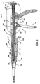
- Tensioning apparatus 100 includes a handle 102 and an elongated member 104 extending distally from the handle 102, and defining a longitudinal axis "a".
- Handle 102 includes frame 106 having a stationary grip and a movable grip 108 piyotally mounted within the frame 106 about pivot pin 110.
- Movable grip 108 includes pawl 114 which forms part of the ratchet mechanism for tensioning the cable.
- Pawl 114 pivots about pivot pin 116 and has a coil spring 118 which biases the pawl 114 distally to a normally engaged position corresponding to an operative position of the ratchet mechanism as depicted in FIG. 2.
- Coil spring 118 is connected to handle 102 through pin 120.
- An elongated actuating member 122 extends through frame 106 and elongate member 104.
- Actuating member 122 includes an inner rod 124 and an outer sleeve 126 coaxially mounted about the rod 124.
- Outer sleeve 126 is adapted for rotational movement relative to rod 124 and has control knob 128 coaxially mounted to its proximal end through stationary screw 131.
- Outer sleeve 126 includes ratchet teeth 130 which cooperate with pawl 114 of movable grip 108 to move outer sleeve 126. Outer sleeve 126 further defines a longitudinal slot 132 within the elongate member 104 in which an internal sleeve locking pin 134 is received (FIG. 2).
- locking knob 128 is rotatable about the longitudinal axis "a” through at least three positions, namely, “release”, “tension” and “lock” positions, to cause rotational movement of the outer sleeve 126 through three corresponding positions.
- “tension” position which is depicted in FIG. 2
- ratchet teeth 130 of outer sleeve 126 are engaged with pawl 114, thereby permitting the outer sleeve 126 to move upon movement of movable grip 108 to tension the cable.
- sleeve locking pin 134 is disposed in longitudinal slot 132 of the outer sleeve 126 such that the locking pin 134 traverses the longitudinal slot 132 during axial movement of outer sleeve.
- This relationship is shown schematically in FIG. 6A.
- control knob 128 is rotated in a counter-clockwise direction (FIG. 5) to rotate outer sleeve 126, i.e., outer sleeve 126 is angularly displaced whereby ratchet teeth 130 are disengaged from pawl 114 thereby permitting actuating member 122 to move without restriction in either the proximal direction or distal direction.
- control knob 128 In the "lock” position, control knob 128 is rotated clockwise with respect to FIG. 5, "1/4" turn through an angular displacement of 90°. In this position, internal locking pin 134 is received within a transverse groove 136 extending from longitudinal slot 132 of outer sleeve 126 thereby preventing the outer sleeve 126 from moving axially as depicted in the schematic view of FIG. 6B. Thus, in the "lock” position, the instrument is not capable of being used in a tensioning mode of operation.
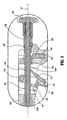
- the pawl mechanism further includes a ratchet lock 138 disposed within frame 106 of handle 102 adjacent control knob 128.
- Ratchet lock 138 moves transversely relative to the longitudinal axis "a" within slot 140 of frame 106 to releasably engage/disengage ratchet teeth 130 of actuating member 122.
- Ratchet lock 138 is biased to the engaged position depicted in FIG. 3 by coil spring 142.
- Ratchet lock 138 is adapted to releasably lock outer sleeve 126 of actuating member 122 subsequent to each incremental movement of the outer sleeve 126 in a proximal or tensioning direction, i.e., the ratchet lock 138 is displaced downwardly upon engagement of pawl 114 with a crest 130c of each respective ratchet tooth whereby upon clearance of the crest 130c the ratchet lock 138 engages the leading vertical surface 130v of the tooth. Accordingly, when in the "tension" condition of control knob 128 the pawl mechanism releasably incrementally locks outer sleeve 126 actuating member 122 while preventing distal loosening movement thereof. Ratchet lock 138 also provides an audible signal during each "click" of the ratchet teeth to indicate the progression of the tensioning procedure.
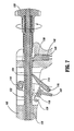
- apparatus 100 further includes a cable engaging pawl mechanism 144 adjacent its distal end.
- Cable engaging pawl mechanism 144 includes plate 146 which is operatively connected to outer sleeve 126 of actuating member 122 through screw 148. Plate 146 moves longitudinally upon longitudinal movement of outer sleeve 126.
- a pair of cable engaging pawls 150 are pivotally mounted to plate 146 through pivot screws 152 on opposed sides of elongated member 104. Each cable engaging pawl 150 is movable about screw 152 between a cable engaging position depicted in FIGs. 4, 8 and 9 and a cable release position. In the engaging position depicted in FIG. 9, the pawls 150 clamp the cable ends "e" against respective vertical surfaces 154 of plate 146.
- Each pawl 150 is normally biased to the engaged position through torsional spring 155 which is coaxially mounted about each screw 152.
- a cable release trigger 156 extending beneath elongate member 104 moves the pair of cable engaging pawls 150 between the cable engaging and release positions. More particularly, release trigger 156 includes a U-shaped portion 158 engageable by the index finger of the user and release rod 160 which extends to plate 146. Release rod 160 is operatively connected to a pair of cam pins 162 which are received within corresponding slots 164 of plate 146. Each cam pin 162 traverses its respective slot 164 upon longitudinal movement of release trigger 156 to open and close cable engaging pawls 150.
- release trigger 156 upon depressing or proximal movement of release trigger 156, the cam pins 162 connected to the release rod 160 move proximally within slots 164 to engage pawl 150 to open the pawls 150 to the position depicted in FIG. 10. Release of release trigger 156 permits pawls 150 to return to their normal engaged position under the influence of torsion springs 155.
- tensioner apparatus 100 further includes a graduated spring scale 170 disposed adjacent control knob 128 to indicate to the user the degree of tension of the cable.
- Spring scale 170 includes spring 172 and an indicator pin 174 which is operatively connected to the pin 172. Pin 172 extends through slot 176 of indicator panel 178.
- Spring 172 operatively engages the proximal end of outer sleeve 126 of actuating member 122. When the outer sleeve 122 is displaced rearwardly upon movement of tensioning trigger 108, spring 172 is compressed accordingly.
- the degree of compression of spring 172 which is directly related to the forces on actuating member 122 through the tensioned cable is indicated by the location of scale pin 174 relative to the graduated markings on the indicator panel 178. This permits the surgeon to readily obtain the level of tension of the cable.
- tensioning apparatus 100 further includes a distal bull nose 180.
- Bullnose 180 includes opposed cable receiving grooves 182 (phantom) which receive each cable end "e” prior to passing through the cable pawl mechanism 144.
- Apparatus 100 also includes a plastic collar 184 having grooves 186 which receives the extreme free ends of the cable "c”.
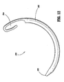
- Hook passer 200 is intended to pass the SecureStrandTM cable about adjacent vertebral bodies.
- Hook passer 200 includes a hook body 202 defining a general semi-circular shape and having an eye loop 204 at a trailing end and a narrowed blunt entry end 206.
- Eye loop 204 is generally elongated and is dimensioned for reception of the looped cable end. During manufacture, eye loop 204 is bent in itself to define an open hook appearance detailed in the Figure.
- Ligature passer 300 is also intended for looping the cable end with respect to the vertical bodies and includes handle 302 and elongated portion 304 extending distally from the handle 302.
- Elongated portion 302 includes an arcuate end portion 306 which is bent between an angle ranging about 70° - 110° relative to the axis "a" of the elongated portion.
- the extreme distal end of the ligature passer includes an eye loop 308 dimensioned for reception of the looped SecureStrandTM cable.
- the handle 302 includes a knurled portion 308 to facilitate gripping engagement by the user.
- system 100 for spinal stabilization will now be discussed. Subsequent to removal of a portion of the vertebrae and/or removal of an intervertebral disc, the spine is to be stabilized for healing and fusion. A three foot length of SecureStrandTM cable is cut from a cable roll and folded upon itself. With the assistance of hook passer 200 or ligature passer 300, depending on the preference of the surgeon, the looped end of the cable “c" may be engaged to respective eye loops of the passers, and the passers are manipulated to pass the cable "c" beneath a pair of opposed vertebrae V 1 , V 2 , i.e., the spinous process or adjacent lamina as depicted in FIG. 14.
- a racking hitch is formed in the looped cable end by inwardly twisting the cable loop upon itself to the orientation depicted in FIG. 15.
- a bone graft "b” may be placed between the vertebrae. Thereafter, both free ends “e” of the cable “c” are pulled through the racking hitch as depicted in FIG. 16. The bone graft "b” is shown in FIG. 16. Both free ends are advanced in order to close the racking hitch against'the vertebral bodies V 1 , V 2 .
- the half hitch is advanced to abut the racking hitch to secure the bone graft between the adjacent vertebrae V 1 , V 2 .
- the half hitch is tightened with moderate hand pressure.
- Tensioner apparatus 100 is introduced into the surgical site.
- a first free end “e” of the cable “c” is positioned about the bull nose 180 of the apparatus with the cable receiving groove 182 and the second free end “e” is positioned within the opposed groove 182 as depicted in FIG. 9.
- the cable release trigger is depressed to outwardly displace the cable engaging pawls 150 to permit the cable ends "e” to be passed within the openings defined between the pawls 150 and the vertical surfaces 154 of plate 146.
- the extreme ends of the cable "c” are positioned within grooves 186 of holder 184 as also depicted in FIG. 10.
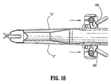
- Movable grip 108 is actuated to move, through action of the ratchet mechanism, actuating member 122, plate 146 and cable engaging pawls 150 proximally as depicted in FIG. 18 to tighten the cable ends.
- spring scale 170 is continually monitored to monitor the desired degree of tension to the cable strands. Once the desired level of tension is achieved, control knob 128 is rotated to the "release” position, and the control knob is pushed forwardly. Then, the control knob is rotated to the "lock” position. The cable release trigger is depressed to release the cable from the pawls and the ends of the cable are removed from the plastic holder. As depicted in FIG.
- a second half hitch opposite to the first half hitch is created to form a square knot.
- a third half hitch is then formed opposite the second half hitch and advanced to the square knot to secure the cable. Thereafter, the free ends of the cable are cut beyond the knob with, e.g., a cauterizer.
Landscapes
- Health & Medical Sciences (AREA)
- Life Sciences & Earth Sciences (AREA)
- Orthopedic Medicine & Surgery (AREA)
- Surgery (AREA)
- Medical Informatics (AREA)
- Engineering & Computer Science (AREA)
- Biomedical Technology (AREA)
- Heart & Thoracic Surgery (AREA)
- Nuclear Medicine, Radiotherapy & Molecular Imaging (AREA)
- Molecular Biology (AREA)
- Animal Behavior & Ethology (AREA)
- General Health & Medical Sciences (AREA)
- Public Health (AREA)
- Veterinary Medicine (AREA)
- Surgical Instruments (AREA)
- Prostheses (AREA)
- Orthopedics, Nursing, And Contraception (AREA)
Abstract
Description
Claims (6)
- A tensioning apparatus for applying a predetermined level of tension to a cable looped about tissue portions, which comprises:a handle;an elongated member extending from the handle and defining a longitudinal axis;first and second cable engaging pawls mounted to the elongated member for releasably engaging respective ends of the cable;a movable grip mounted to the handle; andan actuating member connected to the movable grip, the actuating member operatively connected to the cable engaging pawls whereby movement of the movable grip causes corresponding movement of the cable engaging pawls to tension the cable.
- The tensioning apparatus according to any preceding claim further including a manually engageable release member, the release member movable to move the cable engaging pawls to a disengaged position with respect to the cable ends.
- The tensioning apparatus according to any preceding claim, wherein the cable engaging pawls are normally biased to an engaged position with respect to the cable ends.
- The tensioning apparatus according to any preceding claim, including a ratchet and pawl associated with the movable grip and actuating member for providing incremental movements of the actuating member.
- The tensioning apparatus according to any preceding claim, including a control knob for controlling operation, the control knob being movable between three positions corresponding to lock, tension and release positions, wherein the lock position, the actuating member is prevented from axially moving in a tensioning direction, wherein the tension position, the ratchet and pawl are engaged with the actuating member to permit axial movement of the actuating member in the tensioning direction, and wherein, in the release position, the ratchet and pawl are disengaged thereby permitting unrestricted movement of the actuating movement in the tensioning direction and a release direction.
- The tensioning apparatus according to any preceding claim, including a second pawl engageable with the ratchet to prevent movement of the actuating member in the release direction.
Applications Claiming Priority (2)
| Application Number | Priority Date | Filing Date | Title |
|---|---|---|---|
| US23716900P | 2000-10-02 | 2000-10-02 | |
| US237169P | 2000-10-02 |
Publications (2)
| Publication Number | Publication Date |
|---|---|
| EP1192908A2 true EP1192908A2 (en) | 2002-04-03 |
| EP1192908A3 EP1192908A3 (en) | 2004-05-26 |
Family
ID=22892605
Family Applications (1)
| Application Number | Title | Priority Date | Filing Date |
|---|---|---|---|
| EP01121740A Withdrawn EP1192908A3 (en) | 2000-10-02 | 2001-09-18 | System and method for spinal reconstruction |
Country Status (5)
| Country | Link |
|---|---|
| US (1) | US6689140B2 (en) |
| EP (1) | EP1192908A3 (en) |
| JP (1) | JP2002153477A (en) |
| AU (1) | AU773776B2 (en) |
| CA (1) | CA2357644A1 (en) |
Cited By (5)
| Publication number | Priority date | Publication date | Assignee | Title |
|---|---|---|---|---|
| WO2008073947A3 (en) * | 2006-12-12 | 2008-09-25 | Synthes Usa | Wire twister |
| WO2015125303A1 (en) * | 2014-02-24 | 2015-08-27 | 株式会社田中医科器械製作所 | Surgical tensioner |
| WO2015106300A3 (en) * | 2014-01-10 | 2015-11-19 | Leon Norman Van Der Walt | Orthopaedic tying device |
| CN106488751A (en) * | 2013-12-05 | 2017-03-08 | 乔纳森·法伊贝尔 | Device for tensioning devices for fusion, stabilization and/or fixation of bones |
| EP3319528A4 (en) * | 2015-07-07 | 2019-03-20 | K2M, Inc. | SPINAL CONSTRUCTION WITH FLEXIBLE ELEMENT |
Families Citing this family (135)
| Publication number | Priority date | Publication date | Assignee | Title |
|---|---|---|---|---|
| US6319252B1 (en) | 1999-07-23 | 2001-11-20 | Mcdevitt Dennis | System and method for attaching soft tissue to bone |
| US6527794B1 (en) | 1999-08-10 | 2003-03-04 | Ethicon, Inc. | Self-locking suture anchor |
| US7094258B2 (en) * | 1999-08-18 | 2006-08-22 | Intrinsic Therapeutics, Inc. | Methods of reinforcing an annulus fibrosis |
| US8323341B2 (en) | 2007-09-07 | 2012-12-04 | Intrinsic Therapeutics, Inc. | Impaction grafting for vertebral fusion |
| US7972337B2 (en) * | 2005-12-28 | 2011-07-05 | Intrinsic Therapeutics, Inc. | Devices and methods for bone anchoring |
| JP4247519B2 (en) * | 1999-08-18 | 2009-04-02 | イントリンジック セラピューティックス インコーポレイテッド | Apparatus and method for nucleus augmentation and retention |
| WO2004100841A1 (en) * | 1999-08-18 | 2004-11-25 | Intrinsic Therapeutics, Inc. | Devices and method for augmenting a vertebral disc nucleus |
| US7553329B2 (en) * | 1999-08-18 | 2009-06-30 | Intrinsic Therapeutics, Inc. | Stabilized intervertebral disc barrier |
| US7998213B2 (en) * | 1999-08-18 | 2011-08-16 | Intrinsic Therapeutics, Inc. | Intervertebral disc herniation repair |
| US7717961B2 (en) | 1999-08-18 | 2010-05-18 | Intrinsic Therapeutics, Inc. | Apparatus delivery in an intervertebral disc |
| US6733506B1 (en) | 2000-11-16 | 2004-05-11 | Ethicon, Inc. | Apparatus and method for attaching soft tissue to bone |
| EP1509148B1 (en) * | 2002-05-21 | 2011-03-16 | Warsaw Orthopedic, Inc. | Vertebrae bone anchor and cable for coupling it to a rod |
| FR2842724B1 (en) | 2002-07-23 | 2005-05-27 | Spine Next Sa | VERTEBRAL FASTENING SYSTEM |
| US20060129151A1 (en) * | 2002-08-28 | 2006-06-15 | Allen C W | Systems and methods for securing fractures using plates and cable clamps |
| US7179260B2 (en) * | 2003-09-29 | 2007-02-20 | Smith & Nephew, Inc. | Bone plates and bone plate assemblies |
| JP2007515988A (en) * | 2003-06-20 | 2007-06-21 | イントリンジック セラピューティックス インコーポレイテッド | Device and method for delivering an implant from an annular defect of an intervertebral disc |
| US7815664B2 (en) * | 2005-01-04 | 2010-10-19 | Warsaw Orthopedic, Inc. | Systems and methods for spinal stabilization with flexible elements |
| US7597694B2 (en) * | 2004-01-30 | 2009-10-06 | Warsaw Orthopedic, Inc. | Instruments and methods for minimally invasive spinal stabilization |
| US20050177179A1 (en) * | 2004-02-10 | 2005-08-11 | Baynham Bret O. | Surgical cable system |
| US8523904B2 (en) | 2004-03-09 | 2013-09-03 | The Board Of Trustees Of The Leland Stanford Junior University | Methods and systems for constraint of spinous processes with attachment |
| US7458981B2 (en) * | 2004-03-09 | 2008-12-02 | The Board Of Trustees Of The Leland Stanford Junior University | Spinal implant and method for restricting spinal flexion |
| US7033377B2 (en) * | 2004-05-27 | 2006-04-25 | Mavrek Medical, L.L.C. | Surgical device for capturing, positioning and aligning portions of a severed human sternum |
| US20050277939A1 (en) * | 2004-05-27 | 2005-12-15 | Miller Archibald S Iii | Surgical device for capturing, positioning and aligning portions of a horizontally severed human sternum |
| US8469966B2 (en) * | 2004-09-23 | 2013-06-25 | Smith & Nephew, Inc. | Systems, methods, and apparatuses for tensioning an orthopedic surgical cable |
| US20060089651A1 (en) * | 2004-10-26 | 2006-04-27 | Trudeau Jeffrey L | Apparatus and method for anchoring a surgical rod |
| JP3721189B1 (en) * | 2005-05-02 | 2005-11-30 | アルフレッサファーマ株式会社 | Tightening device for bone fastening cable |
| US20070067034A1 (en) * | 2005-08-31 | 2007-03-22 | Chirico Paul E | Implantable devices and methods for treating micro-architecture deterioration of bone tissue |
| US8998923B2 (en) * | 2005-08-31 | 2015-04-07 | Spinealign Medical, Inc. | Threaded bone filling material plunger |
| FR2890850B1 (en) | 2005-09-20 | 2009-04-17 | Abbott Spine Sa | VERTEBRAL FASTENING SYSTEM |
| FR2890851B1 (en) * | 2005-09-21 | 2008-06-20 | Abbott Spine Sa | ANCILLARY TO TENSION A FLEXIBLE LINK. |
| US20080243194A1 (en) * | 2005-09-26 | 2008-10-02 | The Regents Of The University Of California | Articulating instrumentation for dynamic spinal stabilization |
| JP4955328B2 (en) * | 2005-09-29 | 2012-06-20 | テルモ株式会社 | In vivo tissue closure device |
| US8100946B2 (en) | 2005-11-21 | 2012-01-24 | Synthes Usa, Llc | Polyaxial bone anchors with increased angulation |
| US8758405B2 (en) * | 2006-03-23 | 2014-06-24 | Ethicon Endo-Surgery, Inc | Suture tensioning device |
| US20070270822A1 (en) * | 2006-04-28 | 2007-11-22 | Sdgi Holdings, Inc. | Bone fixation grommet |
| US9750492B2 (en) | 2006-08-04 | 2017-09-05 | Depuy Mitek, Llc | Suture anchor system with tension relief mechanism |
| US9788825B2 (en) | 2006-08-04 | 2017-10-17 | Depuy Mitek, Llc | Suture anchor with relief mechanism |
| US8100928B2 (en) * | 2006-08-10 | 2012-01-24 | Ethicon, Inc. | Morcellator with detachable handle |
| US20090005821A1 (en) * | 2007-06-29 | 2009-01-01 | Spineworks Medical, Inc. | Methods and devices for stabilizing bone compatible for use with bone screws |
| US20090012564A1 (en) * | 2007-03-07 | 2009-01-08 | Spineworks Medical, Inc. | Transdiscal interbody fusion device and method |
| US20100217335A1 (en) * | 2008-12-31 | 2010-08-26 | Chirico Paul E | Self-expanding bone stabilization devices |
| EP2047813A1 (en) | 2007-10-11 | 2009-04-15 | Abbott Spine | Bone fixing system and method of use |
| US8029541B2 (en) | 2006-10-19 | 2011-10-04 | Simpirica Spine, Inc. | Methods and systems for laterally stabilized constraint of spinous processes |
| US8162982B2 (en) | 2006-10-19 | 2012-04-24 | Simpirica Spine, Inc. | Methods and systems for constraint of multiple spine segments |
| US8187307B2 (en) | 2006-10-19 | 2012-05-29 | Simpirica Spine, Inc. | Structures and methods for constraining spinal processes with single connector |
| US20080262549A1 (en) * | 2006-10-19 | 2008-10-23 | Simpirica Spine, Inc. | Methods and systems for deploying spinous process constraints |
| ES2400535T3 (en) | 2006-10-19 | 2013-04-10 | Simpirica Spine, Inc. | Structures to restrict spinous processes with a single connector |
| US20080177298A1 (en) * | 2006-10-24 | 2008-07-24 | St. Francis Medical Technologies, Inc. | Tensioner Tool and Method for Implanting an Interspinous Process Implant Including a Binder |
| US8840621B2 (en) | 2006-11-03 | 2014-09-23 | Innovative Spine, Inc. | Spinal access systems and methods |
| US8025664B2 (en) * | 2006-11-03 | 2011-09-27 | Innovative Spine, Llc | System and method for providing surgical access to a spine |
| WO2008083814A2 (en) * | 2007-01-10 | 2008-07-17 | Dsm Ip Assets B.V. | Method and device for tightening a surgical cable |
| US8308774B2 (en) | 2007-02-14 | 2012-11-13 | Pioneer Surgical Technology, Inc. | Spinal rod reducer and cap insertion apparatus |
| DE602008006537D1 (en) * | 2007-03-02 | 2011-06-09 | Spinealign Medical Inc | FRACTURE-FIXATION SYSTEM |
| WO2008109872A2 (en) * | 2007-03-07 | 2008-09-12 | Spinealign Medical, Inc. | Systems, methods, and devices for soft tissue attachment to bone |
| WO2008121278A2 (en) | 2007-03-30 | 2008-10-09 | Sentreheart, Inc. | Devices, systems, and methods for closing the left atrial appendage |
| US20090276048A1 (en) * | 2007-05-08 | 2009-11-05 | Chirico Paul E | Devices and method for bilateral support of a compression-fractured vertebral body |
| EP2155089A1 (en) * | 2007-05-08 | 2010-02-24 | Spineworks Medical, Inc. | Systems, devices and methods for stabilizing bone |
| CN101715323A (en) | 2007-06-22 | 2010-05-26 | 西普瑞卡-斯宾尼公司 | Methods and devices for controlled flexion restriction of spinal segments |
| US20110172708A1 (en) * | 2007-06-22 | 2011-07-14 | Simpirica Spine, Inc. | Methods and systems for increasing the bending stiffness of a spinal segment with elongation limit |
| US20100036424A1 (en) * | 2007-06-22 | 2010-02-11 | Simpirica Spine, Inc. | Methods and systems for increasing the bending stiffness and constraining the spreading of a spinal segment |
| US9439681B2 (en) | 2007-07-20 | 2016-09-13 | DePuy Synthes Products, Inc. | Polyaxial bone fixation element |
| US20110196492A1 (en) * | 2007-09-07 | 2011-08-11 | Intrinsic Therapeutics, Inc. | Bone anchoring systems |
| US8096998B2 (en) * | 2007-09-26 | 2012-01-17 | Ebi, Llc | External fixation tensioner |
| ATE536824T1 (en) * | 2007-10-23 | 2011-12-15 | Zimmer Spine | FASTENING DEVICES AND STABILIZATION SYSTEMS WITH THESE FASTENING DEVICES |
| US8128635B2 (en) * | 2007-10-23 | 2012-03-06 | Zimmer Spine S.A.S. | Bone fixation tensioning tool and method |
| US8235997B2 (en) | 2008-01-29 | 2012-08-07 | Pioneer Surgical Technology, Inc. | Rod locking instrument |
| US20090216260A1 (en) * | 2008-02-20 | 2009-08-27 | Souza Alison M | Interlocking handle |
| US20090248077A1 (en) * | 2008-03-31 | 2009-10-01 | Derrick William Johns | Hybrid dynamic stabilization |
| US20090292323A1 (en) * | 2008-05-20 | 2009-11-26 | Chirico Paul E | Systems, devices and methods for posterior lumbar interbody fusion |
| CA2726585A1 (en) * | 2008-06-02 | 2009-12-10 | Spinealign Medical, Inc. | Controlled deployment handles for bone stabilization devices |
| EP2296566A4 (en) | 2008-06-06 | 2013-01-02 | Simpirica Spine Inc | Methods and apparatus for deploying spinous process constraints |
| EP2326267B1 (en) * | 2008-06-06 | 2018-04-25 | Empirical Spine, Inc. | Apparatus for locking an implantable band |
| EP2296567B1 (en) | 2008-06-06 | 2014-03-12 | Simpirica Spine, Inc. | Apparatus for locking a band |
| US20100168748A1 (en) * | 2008-07-16 | 2010-07-01 | Knopp Peter G | Morselizer |
| US8257367B2 (en) * | 2008-08-12 | 2012-09-04 | Pioneer Surgical Technology, Inc. | Surgical cable tensioning apparatus and method |
| JP5687197B2 (en) | 2008-09-03 | 2015-03-18 | シンピライカ スパイン, インコーポレイテッド | Method and apparatus for coupling a prosthesis to a spinal segment |
| KR20110073438A (en) | 2008-09-12 | 2011-06-29 | 신세스 게엠바하 | Spinal Stabilization and Guided Fixation System |
| EP2339975B1 (en) | 2008-09-29 | 2015-03-25 | Synthes GmbH | Polyaxial bottom-loading screw and rod assembly |
| US20100191286A1 (en) * | 2008-10-03 | 2010-07-29 | Butler Jesse P | Facet compression system and related surgical methods |
| WO2010062736A1 (en) | 2008-11-03 | 2010-06-03 | Synthes Usa, Llc | Uni-planar bone fixation assembly |
| WO2010088621A1 (en) | 2009-02-02 | 2010-08-05 | Simpirica Spine, Inc. | Sacral tether anchor and methods of use |
| JP5681122B2 (en) | 2009-03-10 | 2015-03-04 | シンピライカ スパイン, インコーポレイテッド | Surgical tether device and method of use |
| JP2012520131A (en) * | 2009-03-10 | 2012-09-06 | シンピライカ スパイン, インコーポレイテッド | Surgical tether device and method of use |
| WO2010104975A1 (en) | 2009-03-10 | 2010-09-16 | Simpirica Spine, Inc. | Surgical tether apparatus and methods of use |
| WO2010114853A1 (en) | 2009-03-30 | 2010-10-07 | Simpirica Spine, Inc. | Methods and apparatus for improving shear loading capacity of a spinal segment |
| CN102448383B (en) | 2009-04-01 | 2015-03-04 | 森特莱哈尔特公司 | Tissue ligation device and controller thereof |
| JP2012523927A (en) | 2009-04-15 | 2012-10-11 | ジンテス ゲゼルシャフト ミット ベシュレンクテル ハフツング | Correction connector for spinal components |
| US8146329B2 (en) * | 2009-05-01 | 2012-04-03 | Pioneer Surgical Technology, Inc. | Method of packaging a surgical cable |
| JP5654584B2 (en) | 2009-06-17 | 2015-01-14 | ジンテス ゲゼルシャフト ミット ベシュレンクテル ハフツング | Correction connector for spine construction |
| DE102010005706A1 (en) * | 2010-01-26 | 2011-07-28 | Stryker Trauma Ag | Clamping device for surgical elements |
| US8900240B2 (en) * | 2010-02-12 | 2014-12-02 | Pioneer Surgical Technology, Inc. | Spinal rod and screw securing apparatus and method |
| JP5412334B2 (en) * | 2010-03-15 | 2014-02-12 | 鬼頭 縁 | Hip replacement surgery support system |
| US8696710B2 (en) | 2010-10-06 | 2014-04-15 | Simpirica Spine, Inc. | Device and accessories for limiting flexion |
| US9023045B2 (en) | 2010-10-28 | 2015-05-05 | Stryker Trauma Sa | Bolt and tool with anti-torque features |
| EP2446841B1 (en) | 2010-10-28 | 2013-05-29 | Stryker Trauma SA | Bolt and tool with anti-torque features |
| CN106974692B (en) * | 2011-06-08 | 2021-06-01 | 森特里心脏股份有限公司 | Tissue ligation device and its tensioning device |
| EP2755582B1 (en) | 2011-09-14 | 2023-07-26 | OrthoPediatrics Corp. | Tether clamp and implantation system |
| US8932296B2 (en) * | 2011-09-27 | 2015-01-13 | Oak Tree Engineering Llc | Spinal rod persuader |
| US9265543B2 (en) | 2011-12-27 | 2016-02-23 | Pioneer Surgical Technology, Inc. | Bone plate system and method |
| US8984720B2 (en) | 2011-12-28 | 2015-03-24 | Pioneer Surgical Technology, Inc. | Tensioning instrument and method |
| MX348150B (en) * | 2012-01-09 | 2017-05-30 | Apifix Ltd | Spinal cage. |
| WO2013106775A1 (en) * | 2012-01-13 | 2013-07-18 | Dallen Medical, Inc. | Actuator for band tensioning system |
| US9662235B2 (en) * | 2012-04-04 | 2017-05-30 | Boston Scientific Scimed, Inc. | Handle for delivering medical device |
| US9561064B2 (en) | 2012-11-21 | 2017-02-07 | Pioneer Surgical Technology, Inc. | Bone plate system and method |
| US10765465B2 (en) | 2012-11-21 | 2020-09-08 | A&E Advanced Closure Systems, Llc | Tensioning instrument |
| US10034692B2 (en) | 2013-03-05 | 2018-07-31 | Globus Medical, Inc. | Elastic member clamps |
| US9433441B2 (en) | 2013-03-05 | 2016-09-06 | Globus Medical, Inc. | Elastic member clamps |
| US10548644B2 (en) | 2013-03-05 | 2020-02-04 | Globus Medical, Inc. | Elastic member clamps |
| KR20250154547A (en) * | 2013-03-15 | 2025-10-28 | 어플라이드 메디컬 리소시스 코포레이션 | Surgical stapler having actuation mechanism with rotatable shaft |
| US9999454B2 (en) | 2013-12-05 | 2018-06-19 | A&E Advanced Closure Systems, Llc | Bone plate system and method |
| US9820793B1 (en) * | 2014-04-21 | 2017-11-21 | Dallen Medical, Inc. | Tensioning devices and methods for dynamic suture systems |
| US10314635B2 (en) | 2014-05-28 | 2019-06-11 | A&E Advanced Closure Systems, Llc | Tensioning instruments |
| US9931138B2 (en) | 2014-10-15 | 2018-04-03 | Globus Medical, Inc. | Orthopedic extendable rods |
| US20160242825A1 (en) | 2015-02-25 | 2016-08-25 | Warsaw Orthopedic, Inc. | Surgical instrument and method |
| US10022159B2 (en) | 2015-12-18 | 2018-07-17 | Warsaw Orthopedic, Inc. | Surgical instrument and method |
| EP3405131B1 (en) | 2016-01-22 | 2023-07-19 | A&E Advanced Closure Systems, LLC | Bone plate having a connector and a connector for a surgical loop |
| US10368881B2 (en) | 2016-06-03 | 2019-08-06 | Quandary Medical, Llc | Method and apparatus for minimally invasive posterolateral spinal fusion |
| US10010350B2 (en) | 2016-06-14 | 2018-07-03 | Stryker European Holdings I, Llc | Gear mechanisms for fixation frame struts |
| AU2017302286B2 (en) | 2016-07-26 | 2022-08-18 | Orthopediatrics Corp. | Orthopedic tethered implants and system |
| CA3031931C (en) | 2016-07-29 | 2022-10-04 | A&E Advanced Closure Systems, Llc | Surgical cable tensioner |
| US10603078B2 (en) * | 2016-10-26 | 2020-03-31 | Warsaw Orthopedic, Inc. | Surgical instrument and method |
| KR101790894B1 (en) | 2016-10-31 | 2017-10-26 | 전북대학교병원 | Apparatus for skeletal traction |
| US10307186B2 (en) | 2016-12-02 | 2019-06-04 | Nuvasive, Inc. | Surgical band clamp system |
| US10874433B2 (en) | 2017-01-30 | 2020-12-29 | Stryker European Holdings I, Llc | Strut attachments for external fixation frame |
| WO2018237276A1 (en) | 2017-06-23 | 2018-12-27 | Orthopediatrics Corp. | INSERTION APPARATUS FOR INTRAMEDULAR NAILS |
| US10667845B2 (en) * | 2017-07-19 | 2020-06-02 | Mayo Foundation For Medical Education And Research | Vertebral tethering |
| USD894385S1 (en) | 2017-10-27 | 2020-08-25 | Orthopediatrics Corp. | Orthopedic tool |
| US11020149B2 (en) * | 2018-02-28 | 2021-06-01 | Globus Medical Inc. | Scoliosis correction systems, methods, and instruments |
| US11819255B2 (en) | 2019-10-07 | 2023-11-21 | Ortho Development Corporation | Tether tensioning instrumentation and related methods |
| IT202000007894A1 (en) * | 2020-04-15 | 2021-10-15 | Medacta Int Sa | DEVICE FOR TENSIONING A SURGICAL WIRE AND KIT FOR CIRCLING A BONE |
| US12458420B2 (en) | 2020-10-07 | 2025-11-04 | Globus Medical, Inc. | Systems and methods for surgical procedures using band clamp implants and tensioning instruments |
| US11771475B2 (en) | 2020-10-07 | 2023-10-03 | Globus Medical, Inc. | Systems and methods for surgical procedures using band clamp implants and tensioning instruments |
| US11974785B2 (en) | 2020-10-16 | 2024-05-07 | Globus Medical, Inc | Band clamp implants |
| US12213706B2 (en) | 2020-10-07 | 2025-02-04 | Globus Medical, Inc. | Systems and methods for surgical procedures using band clamp implants and tensioning instruments |
| EP4144311B1 (en) * | 2021-09-02 | 2024-12-11 | Globus Medical, Inc. | Systems for surgical procedures using band clamp implants and tensioning instrument |
Family Cites Families (40)
| Publication number | Priority date | Publication date | Assignee | Title |
|---|---|---|---|---|
| GB1194721A (en) * | 1967-07-14 | 1970-06-10 | Thomas & Betts Corp | Tool for Tightening and Cutting Straps |
| US4570618A (en) | 1983-11-23 | 1986-02-18 | Henry Ford Hospital | Intervertebral body wire stabilization |
| US4790303A (en) | 1987-03-11 | 1988-12-13 | Acromed Corporation | Apparatus and method for securing bone graft |
| GB8716925D0 (en) | 1987-07-17 | 1987-08-26 | Mehdian S M H | Apparatus for treatment of spinal disorders |
| US5116340A (en) | 1989-01-26 | 1992-05-26 | Songer Robert J | Surgical securance apparatus |
| US4966600A (en) | 1989-01-26 | 1990-10-30 | Songer Robert J | Surgical securance method |
| IT8903410A0 (en) * | 1989-04-03 | 1989-04-03 | Citieffe Srl | CLAMP DEVICE FOR TENSIONING TRACTION WIRES IN ORTHOPEDIC SURGERY |
| US5123910A (en) | 1990-11-07 | 1992-06-23 | Mcintosh Charles L | Blunt tip surgical needle |
| US5304178A (en) | 1992-05-29 | 1994-04-19 | Acromed Corporation | Sublaminar wire |
| FR2693364B1 (en) | 1992-07-07 | 1995-06-30 | Erpios Snc | INTERVERTEBRAL PROSTHESIS FOR STABILIZING ROTATORY AND FLEXIBLE-EXTENSION CONSTRAINTS. |
| GB9217578D0 (en) | 1992-08-19 | 1992-09-30 | Surgicarft Ltd | Surgical implants,etc |
| US5312410A (en) * | 1992-12-07 | 1994-05-17 | Danek Medical, Inc. | Surgical cable tensioner |
| US5496318A (en) | 1993-01-08 | 1996-03-05 | Advanced Spine Fixation Systems, Inc. | Interspinous segmental spine fixation device |
| US5352225A (en) | 1993-01-14 | 1994-10-04 | Yuan Hansen A | Dual-tier spinal clamp locking and retrieving system |
| US5449361A (en) | 1993-04-21 | 1995-09-12 | Amei Technologies Inc. | Orthopedic cable tensioner |
| US5476465A (en) | 1993-04-21 | 1995-12-19 | Amei Technologies Inc. | Surgical cable crimp |
| US5540698A (en) | 1993-04-21 | 1996-07-30 | Amei Technologies Inc. | System and method for securing a medical cable |
| US5431659A (en) | 1993-08-17 | 1995-07-11 | Texas Scottish Rite Hospital For Children | Pneumatic wire tensioner |
| US5395374A (en) | 1993-09-02 | 1995-03-07 | Danek Medical, Inc. | Orthopedic cabling method and apparatus |
| US5417690A (en) | 1993-09-20 | 1995-05-23 | Codman & Shurtleff, Inc. | Surgical cable |
| AU1967095A (en) * | 1994-02-17 | 1995-09-04 | Surgical Accessories, Inc. | Fastener and tensioner for bone securing cable |
| US5788697A (en) | 1994-02-24 | 1998-08-04 | Pioneer Laboratories, Inc. | Cable tensioning device |
| US5536270A (en) * | 1994-02-24 | 1996-07-16 | Pioneer Laboratories, Inc. | Cable system for bone securance |
| US5545168A (en) | 1994-03-11 | 1996-08-13 | Burke; Dennis W. | Apparatus for both tensioning and crimping a surgical wire |
| US5569253A (en) | 1994-03-29 | 1996-10-29 | Danek Medical, Inc. | Variable-angle surgical cable crimp assembly and method |
| US5611801A (en) | 1994-11-29 | 1997-03-18 | Pioneer Laboratories, Inc. | Method and apparatus for bone fracture fixation |
| NZ272994A (en) | 1995-09-12 | 2001-06-29 | C G Surgical Ltd | Spinal prosthesis device which stabilises lamina after laminoplasty |
| US5913875A (en) | 1996-05-30 | 1999-06-22 | Ethicon, Inc. | Taper point needle |
| US5741261A (en) | 1996-06-25 | 1998-04-21 | Sdgi Holdings, Inc. | Minimally invasive spinal surgical methods and instruments |
| DE19627864C2 (en) | 1996-07-11 | 2003-05-08 | Aesculap Ag & Co Kg | Surgical jig |
| DE19628147C2 (en) | 1996-07-12 | 2003-02-20 | Aesculap Ag & Co Kg | Surgical device for fixing bone elements |
| US5766218A (en) | 1996-10-01 | 1998-06-16 | Metamorphic Surgical Devices, Inc. | Surgical binding device and method of using same |
| US5810832A (en) | 1996-12-27 | 1998-09-22 | Blasingame; James | Instrument for placement of cerclage wire |
| US5769894A (en) | 1997-02-05 | 1998-06-23 | Smith & Nephew, Inc. | Graft attachment device and method of attachment |
| US5964769A (en) * | 1997-08-26 | 1999-10-12 | Spinal Concepts, Inc. | Surgical cable system and method |
| US5997542A (en) | 1997-11-18 | 1999-12-07 | Biomet, Inc. | Surgical wire assembly and method of use |
| US5919199A (en) | 1998-01-14 | 1999-07-06 | Mers Kelly; William Charles | Suture device |
| US5964765A (en) | 1998-04-16 | 1999-10-12 | Axya Medical, Inc. | Soft tissue fixation device |
| US5989256A (en) | 1999-01-19 | 1999-11-23 | Spineology, Inc. | Bone fixation cable ferrule |
| US6146386A (en) * | 1999-02-04 | 2000-11-14 | Sdgi Holdings, Inc. | Cable operated bone anchor compressor |
-
2001
- 2001-09-18 EP EP01121740A patent/EP1192908A3/en not_active Withdrawn
- 2001-09-24 CA CA002357644A patent/CA2357644A1/en not_active Abandoned
- 2001-09-25 AU AU76096/01A patent/AU773776B2/en not_active Ceased
- 2001-09-28 JP JP2001299265A patent/JP2002153477A/en active Pending
- 2001-10-01 US US09/968,694 patent/US6689140B2/en not_active Expired - Fee Related
Cited By (9)
| Publication number | Priority date | Publication date | Assignee | Title |
|---|---|---|---|---|
| WO2008073947A3 (en) * | 2006-12-12 | 2008-09-25 | Synthes Usa | Wire twister |
| CN106488751A (en) * | 2013-12-05 | 2017-03-08 | 乔纳森·法伊贝尔 | Device for tensioning devices for fusion, stabilization and/or fixation of bones |
| EP3076887A4 (en) * | 2013-12-05 | 2017-08-30 | Feibel, Jonathan | Device for tensioning apparatus for fusion, stabilization, and/or fixation of bones |
| US9907598B2 (en) | 2013-12-05 | 2018-03-06 | Jonathan Feibel | Device for tensioning apparatus for fusion, stabilization, and/or fixation of bones |
| CN106488751B (en) * | 2013-12-05 | 2019-06-11 | 乔纳森·法伊贝尔 | Device for tensioning an apparatus for fusion, stabilization and/or fixation of bones |
| WO2015106300A3 (en) * | 2014-01-10 | 2015-11-19 | Leon Norman Van Der Walt | Orthopaedic tying device |
| WO2015125303A1 (en) * | 2014-02-24 | 2015-08-27 | 株式会社田中医科器械製作所 | Surgical tensioner |
| EP3319528A4 (en) * | 2015-07-07 | 2019-03-20 | K2M, Inc. | SPINAL CONSTRUCTION WITH FLEXIBLE ELEMENT |
| US11051860B2 (en) | 2015-07-07 | 2021-07-06 | K2M, Inc. | Spinal construct with flexible member |
Also Published As
| Publication number | Publication date |
|---|---|
| AU7609601A (en) | 2002-04-11 |
| JP2002153477A (en) | 2002-05-28 |
| US20020072753A1 (en) | 2002-06-13 |
| EP1192908A3 (en) | 2004-05-26 |
| US6689140B2 (en) | 2004-02-10 |
| CA2357644A1 (en) | 2002-04-02 |
| AU773776B2 (en) | 2004-06-03 |
Similar Documents
| Publication | Publication Date | Title |
|---|---|---|
| US6689140B2 (en) | System and method for spinal reconstruction | |
| US12396765B2 (en) | Instruments and methods for tensioning a spinal tether | |
| US9393063B2 (en) | Tether tensioning instrument | |
| US5449361A (en) | Orthopedic cable tensioner | |
| US7556630B2 (en) | Flexible member tensioning instruments and methods | |
| CA2141911C (en) | Surgical crimping device and method of use | |
| US8216241B2 (en) | Instruments and methods for manipulating a spinal fixation element | |
| US8469966B2 (en) | Systems, methods, and apparatuses for tensioning an orthopedic surgical cable | |
| US8696710B2 (en) | Device and accessories for limiting flexion | |
| JPH06319742A (en) | Fixing system and fixing method for fixing medical cable, medical cable fixing device, and crimping and cutting device | |
| WO1993015680A1 (en) | Device for tightening a loop in a wire or cable |
Legal Events
| Date | Code | Title | Description |
|---|---|---|---|
| PUAI | Public reference made under article 153(3) epc to a published international application that has entered the european phase |
Free format text: ORIGINAL CODE: 0009012 |
|
| AK | Designated contracting states |
Kind code of ref document: A2 Designated state(s): AT BE CH CY DE DK ES FI FR GB GR IE IT LI LU MC NL PT SE TR |
|
| AX | Request for extension of the european patent |
Free format text: AL;LT;LV;MK;RO;SI |
|
| RAP1 | Party data changed (applicant data changed or rights of an application transferred) |
Owner name: HOWMEDICA OSTEONICS CORP. |
|
| PUAL | Search report despatched |
Free format text: ORIGINAL CODE: 0009013 |
|
| RAP1 | Party data changed (applicant data changed or rights of an application transferred) |
Owner name: HOWMEDICA OSTEONICS CORP. |
|
| AK | Designated contracting states |
Kind code of ref document: A3 Designated state(s): AT BE CH CY DE DK ES FI FR GB GR IE IT LI LU MC NL PT SE TR |
|
| AX | Request for extension of the european patent |
Extension state: AL LT LV MK RO SI |
|
| RIC1 | Information provided on ipc code assigned before grant |
Ipc: 7A 61B 17/58 A |
|
| RAP1 | Party data changed (applicant data changed or rights of an application transferred) |
Owner name: PIONEER LABORATORIES, INC. |
|
| AKX | Designation fees paid | ||
| REG | Reference to a national code |
Ref country code: DE Ref legal event code: 8566 |
|
| STAA | Information on the status of an ep patent application or granted ep patent |
Free format text: STATUS: THE APPLICATION IS DEEMED TO BE WITHDRAWN |
|
| 18D | Application deemed to be withdrawn |
Effective date: 20041127 |