EP1192870A1 - Buckle - Google Patents
Buckle Download PDFInfo
- Publication number
- EP1192870A1 EP1192870A1 EP01122454A EP01122454A EP1192870A1 EP 1192870 A1 EP1192870 A1 EP 1192870A1 EP 01122454 A EP01122454 A EP 01122454A EP 01122454 A EP01122454 A EP 01122454A EP 1192870 A1 EP1192870 A1 EP 1192870A1
- Authority
- EP
- European Patent Office
- Prior art keywords
- butting
- buckle
- female body
- male body
- portions
- Prior art date
- Legal status (The legal status is an assumption and is not a legal conclusion. Google has not performed a legal analysis and makes no representation as to the accuracy of the status listed.)
- Granted
Links
Images


Classifications
-
- A—HUMAN NECESSITIES
- A44—HABERDASHERY; JEWELLERY
- A44B—BUTTONS, PINS, BUCKLES, SLIDE FASTENERS, OR THE LIKE
- A44B11/00—Buckles; Similar fasteners for interconnecting straps or the like, e.g. for safety belts
- A44B11/25—Buckles; Similar fasteners for interconnecting straps or the like, e.g. for safety belts with two or more separable parts
- A44B11/26—Buckles; Similar fasteners for interconnecting straps or the like, e.g. for safety belts with two or more separable parts with push-button fastenings
- A44B11/266—Buckles; Similar fasteners for interconnecting straps or the like, e.g. for safety belts with two or more separable parts with push-button fastenings with at least one push-button acting parallel to the main plane of the buckle and perpendicularly to the direction of the fastening action
-
- A—HUMAN NECESSITIES
- A44—HABERDASHERY; JEWELLERY
- A44B—BUTTONS, PINS, BUCKLES, SLIDE FASTENERS, OR THE LIKE
- A44B11/00—Buckles; Similar fasteners for interconnecting straps or the like, e.g. for safety belts
- A44B11/25—Buckles; Similar fasteners for interconnecting straps or the like, e.g. for safety belts with two or more separable parts
- A44B11/26—Buckles; Similar fasteners for interconnecting straps or the like, e.g. for safety belts with two or more separable parts with push-button fastenings
-
- Y—GENERAL TAGGING OF NEW TECHNOLOGICAL DEVELOPMENTS; GENERAL TAGGING OF CROSS-SECTIONAL TECHNOLOGIES SPANNING OVER SEVERAL SECTIONS OF THE IPC; TECHNICAL SUBJECTS COVERED BY FORMER USPC CROSS-REFERENCE ART COLLECTIONS [XRACs] AND DIGESTS
- Y10—TECHNICAL SUBJECTS COVERED BY FORMER USPC
- Y10T—TECHNICAL SUBJECTS COVERED BY FORMER US CLASSIFICATION
- Y10T24/00—Buckles, buttons, clasps, etc.
- Y10T24/45—Separable-fastener or required component thereof [e.g., projection and cavity to complete interlock]
- Y10T24/45225—Separable-fastener or required component thereof [e.g., projection and cavity to complete interlock] including member having distinct formations and mating member selectively interlocking therewith
- Y10T24/45471—Projection having movable connection between components thereof or variable configuration
- Y10T24/45524—Projection having movable connection between components thereof or variable configuration including resiliently biased projection component or surface segment
- Y10T24/45545—Projection having movable connection between components thereof or variable configuration including resiliently biased projection component or surface segment forming total external surface of projection
- Y10T24/45581—Projection having movable connection between components thereof or variable configuration including resiliently biased projection component or surface segment forming total external surface of projection having inserted end formed by oppositely biased surface segments
Definitions
- the concave portion provided at the center of the male body is formed concavely up to the belt through hole provided in the male body, while the convex portion of the upper plate of the female body that corresponds to the concave portion is extended to a top surface of the belt through hole of the male body or a top surface of a belt hooking rod upon the insertion of the bodies so that the belt is prevented from its loosening.
- the buckle according to the present invention has constitutions as described above, and with these constitutions, the following effects are obtained.
- the butting portions 15, 38 comprising the straight portions 11, 33 and the concave portion 12 or the convex portion 34 are formed on one surface of the female body 1 and the male body 2, and on the opposite surface, linear-form butting portions 15, 38 are formed. Therefore, the butting portions 15, 38 are suitable for a buckle with a directionality, or a curved buckle that enable the male body 2 to be inserted only in a specified direction with respect to the front and rear surfaces and restricts the insertion.
- the convex portion 34 in the butting portion 34 is formed in such a manner to be protruded in a trapezoidal form with the front end slightly narrowed and the concave portion 12 is formed in such a manner to be concavely dented with the inlet expanded, or the convex portion 34 in the butting portions 15, 38 is formed in such a manner to protrude arcuately and the concave portion 12 in such a manner to curve in arcuately, thereby forming the butting portions 15, 38 with the straight portions 11, 33 and the convex portion 34 or the concave portion 12.
- a buckle is finished in a stable and excellent design in which the butting portion 15, 38 allows the convex portion 34 to catch and hold the concave portion 12 at the center with the trapezoidal or arcuate convex portion 34 or opposite concave portion 12 and the movement is restricted at of the straight portions 11, 33 on both sides.
- peripheral corners of straight portions 33 on both sides and the convex portion 34 at the center of the male body 2 are formed one level lower by notching to form a stepped portion 36, which is allowed to be fitted into the convex portion 12 of the female body 1 in an overlapping state. Therefore, the female body 1 can be joined to the male body 2 in a stable condition and satisfactory manner.
- the frame 20 of the male body 2 for attaching the belt can be used effectively by providing the concave portion 12 formed at the center of the male body 2 concavely up to the belt through hole 26 and extending the convex portion 34 of the female body 1 to the belt through hole 26.
Abstract
Description
- The present invention relates to a buckle for tightening a belt comprising a female member formed with a flat housing and a male member having a pair of flexible insertion legs, in which a pair of the flexible insertion legs of the male member are inserted into the housing of the female member and engaged therein.
- A conventional insertion type buckle comprising a female member, that is, female body, formed with a flat housing and a male member, that is, male body, having a pair of flexible insertion legs is well-known to have a butting portion of the female body and the male body, which is formed in a simple straight form when the female body and the male body are engaged. As shown in FIG. 28, a buckle of a type to finish an insertion opening 7' of the flat housing 3' of the female body 1' into a straight form, bring a front end of a side frame on each of both sides in the frame 20' of the belt through portion into contact with the insertion opening 7' edge of the housing 3' in the male body 2', and butt both members each other, is well-known. This kind of buckle is disclosed, for example, in Japanese Patent Application Laid-Open No. 9-135609.
- Furthermore, as shown in FIG. 29, a buckle comprising a female body 1" formed with a
flat housing 3" and amale body 2" having a pair ofinsertion legs 30", in which thebutting portions 15", 38" of the female body 1" and themale body 2", when theinsertion legs 30" of themale body 2" is inserted into thehousing 3" of the female body 1" in an insertion form, are slightly cut off in a curved form at both ends of the female body 1" and formed to slightly protrude in an arcuate form at both ends of themale body 2". Then, the relevant ends are connected at a central straight portion is disclosed in U. S. Patent No. 5590444. - In the conventional buckle described above in which the insertion opening of the housing of the female body and the base of the insertion legs of the male body are formed in a straight line and a butting surface between the female body and the male body is also formed in a straight line. In the buckle shown in FIG. 28, the insertion opening 7' of the housing 3' of the female body 1' is formed in a straight line, and in the male body 2', the front ends of both side frames in the frame 20'of the belt through portion are brought into contact with the insertion opening 7'. As for the buckles described above, the buckles may clatter and lack stability when the female body 1' and the male body 2' are engaged by insertion, and further, no smooth inserting operation is expected only with the guide member 35' at the center when the insertion legs 30' are inserted into the housing.
- In the buckle shown in FIG. 29, because the butting surface between the female body 1" and the
male body 2" is held by the bent portions at the ends on both sides of the buckle when theinsertion legs 30" of themale body 2" is inserted into thehousing 3" of the female body 1", there is such a problem that any clearance on the right and left causes the female body 1" and themale body 2" to slip and results in clattering. - The invention has been made with the above-mentioned problems taken into account, and an object of the invention is to provide a buckle comprising a female body formed with a flat housing and a male body having a pair of flexible insertion legs, wherein when the female body and the male body are inserted to engage, a shape of a plane of a butting surface between the female body and the male body, that is, a butting portion, forms horizontal straight portions on both sides of the butting portion as well as a concave portion at center in one of the bodies and a convex portion in the other body, and the buckle securely prevents rocking of right and left directions at the center of the butting portion, restricts and holds the female body and the male body in a stable condition, prevents clattering of the buckle, and achieves the inserting action under the smooth and stable guide.
- Another object of the invention is to provide a buckle, wherein the butting face comprising the straight portions and the concave or convex portion is formed on both front and rear surfaces of the buckle. With the structure, the butting surface suitable for a buckle having a plane configuration of a side surface is formed and the butting portion can accept the insertion from any surface.
- Also another object of the invention is to provide a buckle of a type that prevents the buckle from being inserted reversely with respect to the front and rear surfaces of the buckle by forming the butting surface comprising the straight portion and the concave or convex portions on one face of the buckle only to form the butting portion suited for the buckle having a curved configuration on the side surface thereof.
- And another object of the invention is to provide a buckle having an ideal butting portion that achieves good guiding capability in inserting action of the female body and the male body and can prevent clattering of the buckle as well as the buckle having the butting portion with good stability and excellent design.
- Still another object of the invention is to provide a buckle that allows the female body and the male body to successfully join by forming the center in the butting surface between the female body and the male body into a concave form for the female body and a convex form for the male body to finish the buckle with stable design, and forming the butting surface of the male body into a special shape.
- Finally, also another object of the invention is to provide a buckle finished into a buckle of special designs by forming the center portion in the butting surface between the female body and the male body into a convex form for the female body and a concave form for the male body, and having the functions that can prevent loosening of the belt attached to the male body.
- In order to achieve the above-mentioned objects, the main aspect of the invention provides a buckle comprising a female body formed with a flat housing and a male body having with a pair of right and left flexible insertion legs which are engaged with each other by insertion, wherein a concave portion or a convex portion is provided at the center of the butting surface on the plane of the female body and the male body, that is, the butting portions when the female body engages with the male body, and the female body and the male body are thereby formed closely in contact.
- Preferably, horizontal straight portions are provided on both sides of the butting surface.
- Preferably, the butting portions comprising straight portions on both sides of the buckle and the concave portion or the convex portion at the center are formed on both front and rear surfaces of the female body and the male body.
- Alternately, the butting portions comprising the straight portions on both sides of the buckle and the concave portion or the convex portion at the center are formed respectively on one surface of the female body and the male body.
- Preferably, the convex portion is formed in such a manner to be protruded in a trapezoidal form where a front end is slightly narrowed, the concave portion is formed in such a manner to be concavely dented with the inlet expanded, and the straight portions and the convex portion or concave portion are combined so as to form the butting portions to be formed in the female body and the male body.
- Alternately, the convex portion is formed in such a manner to protrude arcuately, the concave portion is formed in such a manner to curve in arcuately, and the straight portions and convex portion or concave portion are combined so as to form the butting portions to be formed in the female body and the male body.
- Preferably, the butting portion to be formed in the female body is formed with the straight portions and the concave portion and the butting portion to be formed in the male body is formed with the straight portions and the convex portion, such that both butting portions are combined.
- Alternately, the butting portion to be formed in the female body is formed with the straight portions and the convex portion and the butting portion to be formed in the male body is formed with the straight portions and the concave portion, such that both butting portions are combined.
- Preferably, peripheral ends, that is, corners of the straight portions on both sides and the convex portion at the center of the male body are notched to form a one level lower stepped portion, which is formed to be fitted into the butting portion of the female body 1 in the manner of overlapping.
- Further preferably, the concave portion provided at the center of the male body is formed concavely up to a belt through hole provided in the male body, while the convex portion of the female body that corresponds to the concave portion is extended to the belt through hole upon the insertion of the bodies.
- Alternately, the concave portion provided at the center of the male body is formed concavely up to the belt through hole provided in the male body, while the convex portion of the upper plate of the female body that corresponds to the concave portion is extended to a top surface of the belt through hole of the male body or a top surface of a belt hooking rod upon the insertion of the bodies so that the belt is prevented from its loosening.
-
- FIG. 1 is a perspective view of a buckle according to a first embodiment of the invention.
- FIG. 2 is a front view showing an engagement state of the buckle of FIG.1.
- FIG. 3 is a back view showing the engagement state of the buckle of FIG.1.
- FIG. 4 is a side view showing the engagement state of the buckle of FIG.1.
- FIG. 5 is a front view of a female body of the buckle of FIG.1.
- FIG. 6 is a back view of the female body of the buckle of FIG.1.
- FIG. 7 is a side view of the female body of the buckle of FIG.1.
- FIG. 8 is a cross-sectional view of the buckle of FIG.1 taken along the line VIII-VIII of FIG. 5.
- FIG. 9 is a front view of a male body of the buckle of FIG.1.
- FIG. 10 is a back view of the male body of the buckle of FIG.1.
- FIG. 11 is a side view of the male body of the buckle of FIG.1.
- FIG. 12 is a cross-sectional view of the buckle of FIG. 1 taken along the line XII-XII of FIG. 9.
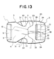
- FIG. 13 is a front view showing an engagement state of a buckle according to a second embodiment of the invention.
- FIG. 14 is a back view showing the engagement state of the buckle of FIG. 13.
- FIG. 15 is a side view showing the engagement state of the buckle of FIG. 13.
- FIG. 16 is a front view showing an engagement state of a buckle according to a third embodiment of the invention.
- FIG. 17 is a back view showing the engagement state of the buckle of FIG. 16.
- FIG. 18 is a front view of a male body of the buckle of FIG. 16.
- FIG. 19 is a cross-sectional view of the buckle of FIG. 16 taken along the line XIX-XIX of FIG. 18.
- FIG. 20 is a front view showing an engagement state of a buckle according to a fourth embodiment of the invention.
- FIG. 21 is a back view showing the engagement state of the buckle of FIG. 20.
- FIG. 22 is a side view showing the engagement state of the buckle of FIG. 20.
- FIG. 23 is a front view of a female body of the buckle of FIG. 20.
- FIG. 24 is a cross-sectional view of the buckle of FIG. 20 taken along the line XXIV-XXIV of FIG. 23.
- FIG. 25 is a front view of a male body of the buckle of FIG. 20.
- FIG. 26 is a cross-sectional view of the buckle of FIG. 20 taken along the line XXVI-XXVI of FIG. 25.
- FIG. 27 is a front view showing an engagement state of a buckle according to a modification.
- FIG. 28 is a front view of a known buckle.
- FIG. 29 is a front view of another known buckle.
-
- Hereinafter, with referring to the drawings, embodiments of a buckle according to the invention will be concretely explained.
- A buckle according to the invention comprises a female body 1 formed with a flat
cylindrical housing 3 and provided with cut-outs 10 provided on both sides of thehousing 3, and amale body 2 having a pair offlexible insertion legs 30 protruded from aframe 20 to which abelt adjusting portion 21 is equipped as shown in FIG. 1, wherein theinsertion legs 30 of themale body 2 is inserted into thehousing 3 of the female body 1 to engage, and the female body 1 and themale body 2 of the buckle are integrally molded by injection molding means with thermoplastic resins such as polyacetal, polyamide, polypropylene, polybutyleneterephthalate, etc.. - To explain the buckle of a first embodiment of the invention shown in FIGs. 1 through 12, the female body 1 is formed from a flat
cylindrical housing 3 comprising anupper plate 4, alower plate 5, andside walls 6 as shown in FIGs. 5 through 8, aninsertion opening 7 to whichflexible insertion legs 30 of themale body 2 can be inserted is provided at one end of thishousing 3,and a belt throughhole 8 and abelt attaching rod 9 are disposed to attach a belt at the other end, and in each of bothside walls 6 of thehousing 3, a cut-out 10 notched concavely is formed so that the flexiblyinsertion legs 30 of themale body 2 can be pressed on its operation. - A horizontal
straight portions 11 are disposed on both sides of theinsertion opening 7 of thehousing 3 and at the center of theinsertion opening 7, aconcave portion 12 dented concavely and having a slightly expanded inlet is provided continuously so as to form the butting surface with themale body 2, that is, the buttingportion 15. In the inside of thehousing 3, apartition piece 13 is disposed so as to protrude on theupper plate 4 and to thelower plate 5 in the central longitudinal direction to guide aguide member 35 of themale body 2. In addition, on the inner surfaces of both of theupper plate 4 and thelower plate 5 on the side of the belt throughhole 8, engagingprotrusions 14 that can be engaged respectively with an engagingportion 32 of theinsertion leg 30 of themale body 2 are protruded. The numeral 16 denotes a core aperture for molding the engagingprotrusion 14. - The
male body 2 has a U-lettershaped frame 20 with abelt adjusting portion 21 provided on one end thereof as shown in FIGs. 9 through 12, and the adjustingportion 21 has a hookingrod 22 for catching the belt and afastening rod 22 for fixing the belt such that they bridge theside frame 24 of theframe 20 in parallel, and a belt throughhole 26 is formed between a base 25 of theframe 20 and the hookingrod 22. The hookingrod 22 has lockingpawls 27 protruded horizontally towards thebase 25, and a wave-like fastening portion 28 is provided at the rear surface of the front end of the hookingrod 23 to prevent the belt from sliding. - The
flexible insertion legs 30 capable of being inserted into thehousing 3 of the female body 1 and engaged therewith are provided on both sides of thebase 25 of theframe 20 so as to protrude, and theflexible insertion legs 30 have an enlargedpressing portions 31, that can be fitted into the cut-out 10 of thehousing 3, at the middle of theinsertion legs 30, and the front end side of theinsertion leg 30 is formed slightly bent inwardly to enable easy insertion and removal to and from thehousing 3 and the engagingportions 32 that can engage with the engagingprotrusions 14 of the female body 1 are formed on the front and rear surfaces of the front end of theinsertion legs 30. When theinsertion leg 30 is inserted in thehousing 3, by pressing thepressing portion 31 of theinsertion leg 30 appearing from the side of thehousing 3, the engagingportion 32 can be separated from the engagingprotrusion 14 and then, themale body 2 removed from the female body 1 in compliance with the warp of theinsertion leg 30. - The front end of the base 25 on both sides of the
frame 20, that is, the portion where theinsertion leg 30 is provided so as to protrude is formed into a horizontalstraight portion 33, and at the center of theframe 20, aconvex portion 34 that protrudes out forward is disposed, and thisconvex portion 34 is formed in a trapezoidal form with the front end slightly narrowed, and the butting surface with the female body 1, that is, the buttingportion 38, is thereby formed. At the front end of this trapezoidalconvex portion 34, aguide member 35 with H-letter shaped cross section is protruded, and theguide member 35 is allowed to be inserted along thepartition piece 13 protruded on the inner surface of thehousing 3. - The
straight portions 33 on both sides in both front and rear surfaces of theframe 20 and the peripheral edge of theconvex portion 34 at the center have the notched corners to form a steppedportion 36 that becomes one step lower around the peripheral edge as shown in FIG. 12. This steppedportion 36 is fitted into theinsertion opening 7 of thehousing 3 in an overlapping manner to secure stable insertion when theinsertion legs 30 of themale body 2 are inserted into thehousing 3 of the female body 1. As shown in FIG. 10, on the rear surface of theconvex portion 34 and thepressing portions 31 of theinsertion legs 30, recesses 37 are formed for reduce the weight of the buckle. - This buckle has a pair of the
flexible insertion legs 30 and guidemember 35 of themale body 2 inserted from theinsertion opening 7 of thehousing 3 of the female body 1, wherein the external surface of theflexible leg 30 is guided by theside wall 6 of thehousing 3 and theguide member 35 is inserted by being guided by thepartition pieces 13 formed on the inner surfaces of theupper plate 4 and thelower plate 5 of thehousing 3, the engagingportions 32 disposed on the front and rear surface of the front ends of theflexible insertion legs 30 are engaged with the engagingprotrusions 14 protruded on the inner surfaces of theupper plate 4 and thelower plate 5 of thehousing 3, so that the buttingportions male body 2 are butted and fixed in a closely contacted condition. To attach the belt to the buckle, one end of the belt is attached to thebelt attaching rod 9 of the female body 1 and the other end is wrapped around the hookingrod 22 from the bottom surface of thebelt fastening rod 23 of thebelt adjustment portion 21 of themale body 2, and is allowed to pass the bottom surface of thefastening member 23 pulled out outward to equip the belt. - The features of the buckle according to the invention lie in the butting surface, that is, the butting
portion 15, formed at theinsertion opening 7 of thehousing 3 of the female body 1 and the butting surface, that is, the buttingportion 38 formed at the front surface of theframe 20 of themale body 2, whereinstraight portions concave portion 12 is formed continuously in contact with thestraight portions convex portion 34 is formed at the center of themale body 2, and when themale body 2 is inserted into the female body 1, theconvex portion 34 at the center is restricted as if theconcave portion 12 holds theconvex portion 34 at the center by thestraight portions concave portion 12 and theconvex portion 34 at the center, thereby positively preventing rocking, that is, clattering of the buckle in the right and left directions in a simple constitution. - To describe a buckle of a second embodiment of the invention shown in FIGs. 13 through 15, the configurations of the top surfaces of the female body 1 and the
male body 2 of this buckle are same as the configurations of the female body 1 and themale body 2 of the buckle of the first embodiment. That is, the female body 1 has the buttingportion 15 formed on theupper plate 4 at the side of theinsertion opening 7 of thehousing 3, with horizontalstraight portions 11 formed on both sides, a concavely dentedconcave portion 12 continuously disposed at the center with the entry slightly expanded, and cut-outs 10 concavely notched are disposed at the middle of theside walls 6 on both sides of thehousing 3. The rear surface of thehousing 3 differs in the constitution from the female body 1 of the first embodiment as shown in FIG. 14, in that the buttingportion 15 of thelower plate 5 of theinsertion opening 7 has thestraight portions 11 on both sides and the whole butting portion is formed in thestraight portion 11 by extending thestraight portions 11 of both sides without forming theconcave portion 12. - Consequently, for the
male body 20, as well, the buttingportion 38 formed at the base 25 on the top surface of theframe 20 has the horizontalstraight portions 33 on both sides, aconvex portion 34 that protrudes forward disposed at the center continuously in contact with thisstraight portion 33, and thisconvex portion 34 is formed in a trapezoidal form with the front end slightly narrowed. The buttingportion 38 formed at thebase 25 of the rear surface of theframe 20 is formed in such a manner that the whole exhibits a horizontalstraight portion 33 as well as the case of the buttingportion 15 of the female body 1. And on both sides of thebase 25 of theframe 20,flexible insertion legs 30 are disposed and aguide member 35 at the center, and thebelt adjusting portion 21 comprising thebelt hooking rod 22 and thefastening rod 23 is disposed on the other side of the frame, and this constitution is the same as themale body 2 of the first embodiment. - The buckle of the type with the butting portions different on the front and the rear is applied to the buckle which is warped entirely as shown in FIG. 15, that is , the buckle of a curved form. In the buckle, the
male body 2 is formed so as to be inserted in a specified direction only with respect to the female body 1, the use other than the normal condition is denied, and it is the feature of this buckle in that themale body 2 is unable to be inserted reversely with respect to the front and rear surfaces. - The corners of the peripheral edge of the butting
portion 38 formed at the base 25 on the front and rear surfaces in themale body 2 of this buckle are notched to form a steppedportion 36, and when the male body is inserted into thehousing 3 of the female body 1, the buttingportions portion 36 of themale body 2 is fitted into theinsertion opening 7 of thehousing 3 in the manner of overlapping, and the male body is able to be held in a stable condition. - To describe a buckle of a third embodiment of the invention shown in FIGs. 16 through 19, for the
housing 3 of the female body 1 of the buckle, the buttingportion 15 formed on theupper plate 4 and thelower plate 5 at theinsertion opening 7 has horizontalstraight portions 11 formed on both sides of thehousing 3 and aconcave portion 12 dented arcuately and curved in at the center continuously in contact with thisstraight portions 11. For themale body 2, the buttingportion 38 formed at thebase 25 of theframe 20 has the horizontalstraight portions 33 formed on both sides and aconvex portion 34 arcuately protruding forwards formed at the center continuously in contact with thisstraight portion 33, which can match theconcave portion 12. The constitution of the female body 1 andmale body 2 of this buckle other than the foregoing is the same as that of the first embodiment. - The butting
portion 38 formed at thebase 25 of theframe 20 on the front and rear surfaces in themale body 2 of this buckle has corners of peripheral edge of thestraight portion 33 formed on both sides of thebase 25 andconvex portion 34 arcuately protruded at the center and the corners were notched to form a steppedportion 36. When themale body 2 is inserted in thehousing 3 of the female body 1, the buttingportions portion 36 of the buttingportion 38 of themale body 2 are fitted into theinsertion opening 7 of thehousing 3 in the manner of overlapping and hold the male body in a stable state. - To describe a buckle of a forth embodiment of the invention shown in FIG. 20 through FIG. 26, according to the buckle, the configurations of the butting
portions male body 2 differ from that of each of the above-mentioned embodiments, and is a buckle in which theconvex portion 34 is formed on the female body 1 and theconcave portion 12 is formed on thefemale body 2, thereby forming buttingportions - To describe this embodiment in detail, as shown in FIGs. 23 and 24, for the female body 1, the
insertion opening 7 in thehousing 3 has the horizontalstraight portions 11 formed on both sides of theupper plate 4 and thelower plate 5 and aconvex portion 34 trapezoidally protruding, with the front end slightly narrowed, formed at the center, thereby forming a buttingportion 15. In the middle of each of theside walls 6 on both sides of thehousing 3, a cut-out 10 concavely notched is disposed, and at the front end of thehousing 3, a belt throughhole 8 and abelt attaching rod 9 are integrally disposed, at the inside of thehousing 3, thepartition pieces 13 are protruded on theupper plate 4 and thelower plate 5 in the central longitudinal direction, and on the inner surfaces on both sides of theupper plate 4 and thelower plate 5 on the side of the belt throughhole 8, an engagingprotrusions 14 are formed. - For the
male body 2, as shown in FIG. 25 and 26, the front surface of thebase 25 of thefame 20 is straight andflexible insertion legs 30 disposed so as to protrude on both right and left sides, and at the middle of theflexible insertion leg 30, anpressing portion 31 is formed, at the front end thereof, the engagingportion 32 is formed on the front and the rear, and at the center of thebase 25, aguide member 35 with the H-letter shaped cross section is disposed so as to protrude. Thebelt hooking rod 22 and thefastening rod 23 are bridged in parallel at theside frame 24 of theframe 20, and between the hookingrod 22 and thebase 25, a belt throughhole 26 is disposed. - For the butting
portion 38 formed at thebase 25 of theframe 20, thestraight portion 33 is formed on each of both sides on both front and rear surface of thebase 25, theconcave portion 12 capable of being fitted in and matching theconvex portion 34 of the female body 1 with the inlet expanded is concavely disposed at the center in the range reaching the belt throughhole 26, and when theinsertion legs 30 and theguide member 35 are inserted into theinsertion opening 7 of thehousing 3 of the female body 1, theconvex portion 34 of the buttingportion 15 disposed in the female body 1 is fitted and fix to theconcave portion 12 of the buttingportion 38 disposed at thebase 25 of theframe 20, and rocking of the buckle in the right and left directions can be prevented by the buttingportions convex portion 34 and theconcave portion 12. - The buckle shown in FIG. 27 shows a modification of the buckle according to the fourth embodiment. What differs from the aforementioned buckles is to form the butting
portion 15 of theconvex portion 34 disposed at theinsertion opening 7 in thehousing 3 of the female body 1 in such a manner as to protrude extendedly up to the top surface of the belt throughhole 26 formed in theframe 2 of themale body 2 or to the top surface of thebelt hooking rod 22, and to bring the buttingportion 15 in contact with the belt inserted through thebelt adjusting portion 21 at the front end of theconvex portion 34 formed in the female body 1, thereby intending to prevent loosening of the belt. - The buckle according to the present invention has constitutions as described above, and with these constitutions, the following effects are obtained.
- According to the invention, there are the effects of preventing rocking in the right and left directions as well as clattering in the buckle, restricting and holding the female body 1 and the
male body 2 in a stable state, and enabling smooth inserting operation with good guide, by providing the buckle comprising the female body 1 formed with aflat housing 3 and themale body 2 having a pair ofinsertion legs 30, in such a manner that horizontalstraight portions concave portion 12 or aconvex portion 34 at the center in the buttingportions male body 2 when the female body 1 engages with themale body 2, and the female body 1 and themale body 2 are thereby formed closely in contact. - Further, the butting
portions straight portions concave portion 12 orconvex portion 34 on both the front and rear surfaces of the female body 1 and themale body 2 is provided. Therefore, there is such an effect that a flat buckle that enables themale body 2 to be inserted from either of both front and rear surfaces and that can be used irrespectively of the front and the rear because the butting surface is symmetrical on the front and the rear. - Furthermore, the butting
portions straight portions concave portion 12 or theconvex portion 34 are formed on one surface of the female body 1 and themale body 2, and on the opposite surface, linear-form butting portions portions male body 2 to be inserted only in a specified direction with respect to the front and rear surfaces and restricts the insertion. - Still further, the
convex portion 34 in the buttingportion 34 is formed in such a manner to be protruded in a trapezoidal form with the front end slightly narrowed and theconcave portion 12 is formed in such a manner to be concavely dented with the inlet expanded, or theconvex portion 34 in the buttingportions concave portion 12 in such a manner to curve in arcuately, thereby forming the buttingportions straight portions convex portion 34 or theconcave portion 12. Consequently, a buckle is finished in a stable and excellent design in which the buttingportion convex portion 34 to catch and hold theconcave portion 12 at the center with the trapezoidal or arcuateconvex portion 34 or oppositeconcave portion 12 and the movement is restricted at of thestraight portions - Further, the butting
portion 15 of the female body 1 is formed with thestraight portions 11 and theconcave portion 12 and the buttingportion 38 of themale body 2 is formed with thestraight portions 33 and theconvex portion 34 or the buttingportion 15 of the female body 1 is formed with thestraight portions 11 and theconvex portion 34 and the buttingportion 38 of themale body 2 is formed with thestraight portions 33 and theconcave portion 12. Consequently, there is such effects that the buckle of different forms with theconcave portion 12 andconvex portion 34 at the center of the buttingportions - And further, the peripheral corners of
straight portions 33 on both sides and theconvex portion 34 at the center of themale body 2 are formed one level lower by notching to form a steppedportion 36, which is allowed to be fitted into theconvex portion 12 of the female body 1 in an overlapping state. Therefore, the female body 1 can be joined to themale body 2 in a stable condition and satisfactory manner. - Further, the
frame 20 of themale body 2 for attaching the belt can be used effectively by providing theconcave portion 12 formed at the center of themale body 2 concavely up to the belt throughhole 26 and extending theconvex portion 34 of the female body 1 to the belt throughhole 26. - Furthermore, there is such effects that loosening of the belt is easily prevented at the
belt adjusting portion 21 in themale body 2 and the buckle can be finished with excellent functions by concavely providing theconcave portion 12 disposed at the center of themale body 2 up to the belt throughhole 26 and extending theconvex portion 34 of theupper plate 4 of the female body 1 to the top surface of the belt throughhole 26 or the top surface of the hookingrod 22. Therefore, the effects achieved by the invention are remarkably notable.
Claims (11)
- A buckle including:a female body (1) formed with a flat housing (3) and a male body (2) having flexible insertion legs (30) which are engaged with each other by insertion,being characterized in that a concave portion or a convex portion (12, 34) is provided at the center of butting portions (15, 38) on the plane of the female body (1) and the male body (2) when the female body (1) engages with the male body (2), and the female body (1) and the male body (2) are thereby formed closely in contact.
- The buckle according to claim 1, characterized in that horizontal straight portions (11, 33) are provided on both sides of a butting surface.
- The buckle according to claim 1, characterized in that butting portions (15, 38) including straight portions (11, 33) and the concave portion (12) or the convex portion (34) are formed on both front and rear surfaces of the female body (1) and the male body (2).
- The buckle according to claim 1, characterized in that the butting portions (15, 38) including the straight portions (11, 33) and the concave portion (12) or the convex portion (34) are formed on one surface of the female body (1) and the male body (2), and on the opposite surface, linear-form butting portions (15, 38) are formed.
- The buckle according to claim 1, characterized in that the convex portion (34) in the butting portions (15, 38) protrudes in a trapezoidal form where a front end is slightly narrowed, the concave portion (12) is concavely dented with the inlet expanded, and the straight portions (11, 33) and the convex portion (34) or concave portion (12) form the butting portions (15, 38).
- The buckle according to claim 1, characterized in that the convex portion (34) in the butting portions (15, 38) protrudes arcuately, the concave portion (12) curves in arcuately, and the straight portions (11, 33) and convex portion (34) or concave portion (12) form the butting portions (15, 38).
- The buckle according to claim 1, characterized in that the butting portion (15) of the female body (1) is formed by the straight portions (11) and the concave portion (12) and the butting portion (38) of the male body (2) is formed by the straight portions (33) and the convex portion (34).
- The buckle according to claim 1, characterized in that the butting portion (15) of the female body (1) is formed by the straight portions (11) and the convex portion (34) and the butting portion (38) of the male body (2) is formed by the straight portions (33) and the concave portion (12).
- The buckle according to claim 7, characterized in that the peripheral corners of straight portions (33) on both sides and the convex portion (34) at the center in the female body (2) are notched to form a one level lower stepped portion (36), which is allowed to be fitted into the butting portion (15) of the female body (1) in a manner of overlapping.
- The buckle according to claim 8, characterized in that the concave portion (12) provided at the center of the male body (2) is formed concavely up to a belt through hole (26), while the convex portion (34) of the female body (1) is extended to the belt through hole (26).
- The buckle according to claim 8, characterized in that the concave portion (12) disposed at the center of the male body (2) is formed concavely up to the belt through hole (26), while the convex portion (34) of the upper plate (4) of the female body (1) is extended to a top surface of the belt through hole (26) or a top surface of a hooking rod (22).
Applications Claiming Priority (2)
| Application Number | Priority Date | Filing Date | Title |
|---|---|---|---|
| JP2000293451A JP3701187B2 (en) | 2000-09-27 | 2000-09-27 | buckle |
| JP2000293451 | 2000-09-27 |
Publications (2)
| Publication Number | Publication Date |
|---|---|
| EP1192870A1 true EP1192870A1 (en) | 2002-04-03 |
| EP1192870B1 EP1192870B1 (en) | 2006-02-01 |
Family
ID=18776237
Family Applications (1)
| Application Number | Title | Priority Date | Filing Date |
|---|---|---|---|
| EP01122454A Expired - Lifetime EP1192870B1 (en) | 2000-09-27 | 2001-09-20 | Buckle |
Country Status (8)
| Country | Link |
|---|---|
| US (1) | US7055226B2 (en) |
| EP (1) | EP1192870B1 (en) |
| JP (1) | JP3701187B2 (en) |
| KR (1) | KR100413942B1 (en) |
| CN (1) | CN1345558A (en) |
| AU (1) | AU757328B2 (en) |
| DE (1) | DE60116937T2 (en) |
| TW (1) | TWM260136U (en) |
Families Citing this family (38)
| Publication number | Priority date | Publication date | Assignee | Title |
|---|---|---|---|---|
| US7753050B2 (en) | 2001-09-07 | 2010-07-13 | Resmed Limited | Headgear connection assembly for a respiratory mask assembly |
| JP4025131B2 (en) * | 2002-07-10 | 2007-12-19 | コクヨ株式会社 | strap |
| AU2004313613B2 (en) | 2004-01-16 | 2011-05-26 | ResMed Pty Ltd | Headgear connection assembly for a respiratory mask assembly |
| US7174609B2 (en) * | 2004-03-19 | 2007-02-13 | Nam-Il Park | Buckle |
| US7020939B2 (en) * | 2004-04-23 | 2006-04-04 | Joseph Anscher | Separable buckle |
| JP4376113B2 (en) * | 2004-04-27 | 2009-12-02 | Ykk株式会社 | buckle |
| US7089633B2 (en) * | 2004-09-15 | 2006-08-15 | Kim Ging Hui Enterprise Co., Ltd. | Side release buckle |
| JP4203461B2 (en) * | 2004-11-02 | 2009-01-07 | Ykk株式会社 | buckle |
| US7100252B2 (en) * | 2005-01-31 | 2006-09-05 | Joseph Anscher | Dual locking buckle |
| JP4769597B2 (en) * | 2006-03-02 | 2011-09-07 | Ykk株式会社 | buckle |
| US8256072B2 (en) * | 2006-12-12 | 2012-09-04 | Illinois Tool Works Inc. | Buckle |
| JP2008178570A (en) | 2007-01-25 | 2008-08-07 | Ykk Corp | Buckle |
| KR100833585B1 (en) * | 2007-03-14 | 2008-05-30 | 한국단자공업 주식회사 | Connector with structure for locking sound generation |
| JP5651282B2 (en) * | 2007-07-03 | 2015-01-07 | Ykk株式会社 | buckle |
| JP4912251B2 (en) * | 2007-08-08 | 2012-04-11 | Ykk株式会社 | buckle |
| JP4969364B2 (en) * | 2007-08-13 | 2012-07-04 | 株式会社ニフコ | Mounting structure |
| JP5020004B2 (en) | 2007-09-05 | 2012-09-05 | Ykk株式会社 | buckle |
| WO2009093313A1 (en) | 2008-01-23 | 2009-07-30 | Ykk Corporation | Buckle |
| US8051542B2 (en) * | 2008-08-13 | 2011-11-08 | Alexander Buday | Detachable lanyard buckle |
| WO2010038308A1 (en) * | 2008-10-03 | 2010-04-08 | Ykk株式会社 | Buckle |
| US8286311B2 (en) * | 2008-10-31 | 2012-10-16 | Jisook Paik | Buckle |
| KR101230729B1 (en) | 2009-03-31 | 2013-02-07 | 와이케이케이 가부시끼가이샤 | Side release buckle |
| CN103211355B (en) * | 2009-03-31 | 2015-09-30 | Ykk株式会社 | Button is opened on side |
| US8267614B2 (en) * | 2009-04-24 | 2012-09-18 | Toyota Motor Engineering & Manufacturing North America, Inc. | Easy install guide slot with snap tab |
| JP5469542B2 (en) * | 2010-06-07 | 2014-04-16 | 株式会社ニフコ | buckle |
| JP5469541B2 (en) * | 2010-06-07 | 2014-04-16 | 株式会社ニフコ | buckle |
| JP5538074B2 (en) * | 2010-06-07 | 2014-07-02 | 株式会社ニフコ | buckle |
| DE112012005879B4 (en) * | 2012-02-16 | 2017-12-28 | Ykk Corporation | clasp |
| CN104114055B (en) * | 2012-02-16 | 2017-04-12 | Ykk株式会社 | Buckle |
| JP2014008312A (en) * | 2012-07-02 | 2014-01-20 | Nifco Inc | Buckle |
| US8863362B2 (en) * | 2012-08-27 | 2014-10-21 | Bison Designs, Llc | Side squeeze buckle with integrated LED light |
| JP5902739B2 (en) * | 2014-03-19 | 2016-04-13 | 株式会社ニフコ | buckle |
| JP3197854U (en) | 2015-03-25 | 2015-06-04 | Ykk株式会社 | buckle |
| KR101777109B1 (en) * | 2015-11-05 | 2017-09-12 | 주식회사 우진프라스틱 | buckle |
| USD883855S1 (en) * | 2018-01-02 | 2020-05-12 | Woojin Plastic Co., Ltd. | Buckle member for bags |
| USD886669S1 (en) | 2018-08-02 | 2020-06-09 | Radio Systems Corporation | D-ring |
| US10617180B1 (en) * | 2018-10-25 | 2020-04-14 | Ying-Chuan Yen | Metal body buckle |
| US11044970B1 (en) * | 2020-03-30 | 2021-06-29 | Duraflex Hong Kong Limited | Attachment system with quick release |
Citations (3)
| Publication number | Priority date | Publication date | Assignee | Title |
|---|---|---|---|---|
| EP0648441A1 (en) * | 1993-10-16 | 1995-04-19 | Ykk Corporation | Buckle |
| FR2783679A1 (en) * | 1998-09-30 | 2000-03-31 | Ykk Corp | Buckle connector for strap has male and female sections with projection on one to retain folded strap for length adjustment |
| US6052875A (en) * | 1991-12-20 | 2000-04-25 | Yoshida Kogyo K.K. | Buckle assembly |
Family Cites Families (12)
| Publication number | Priority date | Publication date | Assignee | Title |
|---|---|---|---|---|
| US3600917A (en) * | 1969-04-08 | 1971-08-24 | Scott & Fetzer Co | Molded keyholder |
| US3979934A (en) * | 1974-09-20 | 1976-09-14 | Penn Corporation | Separable key holder |
| US4679282A (en) * | 1986-06-04 | 1987-07-14 | Feng Lung S | Press fastener |
| JPH0411531Y2 (en) * | 1986-08-12 | 1992-03-23 | ||
| JPH07275012A (en) * | 1994-04-05 | 1995-10-24 | Yoshio Tokuda | Buckle |
| US5590444A (en) | 1994-08-02 | 1997-01-07 | American Cord & Webbing Company, Inc. | Side release buckle with improved distribution of stress under loads |
| JPH08131215A (en) * | 1994-11-02 | 1996-05-28 | Yoshio Tokuda | Plastic buckle |
| US5561891A (en) * | 1995-06-20 | 1996-10-08 | Hsieh; Hsing-Chi | Fastener structure between a diving flipper and a tightening strap thereof |
| US5651166A (en) | 1995-11-13 | 1997-07-29 | Illinois Tool Works Inc. | Method and apparatus for anti-slip webbing adjustment |
| JPH09206113A (en) * | 1995-11-30 | 1997-08-12 | Yoshio Tokuda | Guidless buckle made of plastic |
| USD468233S1 (en) * | 1999-03-31 | 2003-01-07 | Ema Srl | Buckle, particularly for a belt |
| JP3494588B2 (en) * | 1999-05-10 | 2004-02-09 | Ykk株式会社 | Side push open buckle |
-
2000
- 2000-09-27 JP JP2000293451A patent/JP3701187B2/en not_active Expired - Fee Related
-
2001
- 2001-09-19 KR KR10-2001-0057951A patent/KR100413942B1/en not_active IP Right Cessation
- 2001-09-20 EP EP01122454A patent/EP1192870B1/en not_active Expired - Lifetime
- 2001-09-20 DE DE60116937T patent/DE60116937T2/en not_active Expired - Lifetime
- 2001-09-20 AU AU75559/01A patent/AU757328B2/en not_active Ceased
- 2001-09-26 CN CN01135437A patent/CN1345558A/en active Pending
- 2001-09-27 US US09/963,577 patent/US7055226B2/en not_active Expired - Lifetime
- 2001-09-27 TW TW093209560U patent/TWM260136U/en unknown
Patent Citations (3)
| Publication number | Priority date | Publication date | Assignee | Title |
|---|---|---|---|---|
| US6052875A (en) * | 1991-12-20 | 2000-04-25 | Yoshida Kogyo K.K. | Buckle assembly |
| EP0648441A1 (en) * | 1993-10-16 | 1995-04-19 | Ykk Corporation | Buckle |
| FR2783679A1 (en) * | 1998-09-30 | 2000-03-31 | Ykk Corp | Buckle connector for strap has male and female sections with projection on one to retain folded strap for length adjustment |
Also Published As
| Publication number | Publication date |
|---|---|
| JP2002101915A (en) | 2002-04-09 |
| KR20020025017A (en) | 2002-04-03 |
| AU7555901A (en) | 2002-03-28 |
| US7055226B2 (en) | 2006-06-06 |
| CN1345558A (en) | 2002-04-24 |
| TWM260136U (en) | 2005-04-01 |
| KR100413942B1 (en) | 2004-01-07 |
| US20020040514A1 (en) | 2002-04-11 |
| AU757328B2 (en) | 2003-02-13 |
| DE60116937D1 (en) | 2006-04-13 |
| JP3701187B2 (en) | 2005-09-28 |
| DE60116937T2 (en) | 2006-07-27 |
| EP1192870B1 (en) | 2006-02-01 |
Similar Documents
| Publication | Publication Date | Title |
|---|---|---|
| US7055226B2 (en) | Buckle | |
| US5419020A (en) | Separable buckle | |
| US4457052A (en) | Buckle for child's car seat harness | |
| JPH0542728Y2 (en) | ||
| EP1177735B1 (en) | Buckle | |
| US6868591B2 (en) | Infant buckle | |
| US5855057A (en) | Buckle assembly | |
| US8763217B2 (en) | Buckle | |
| KR100673738B1 (en) | Buckle | |
| US5419617A (en) | Detachable chair arm | |
| US20020017012A1 (en) | Three and five point buckle | |
| JPH0228324B2 (en) | ||
| JPH08140712A (en) | Buckle | |
| JP4143927B2 (en) | buckle | |
| EP1052735B1 (en) | Side release buckle | |
| JPH11266908A (en) | Buckle | |
| EP1166674B1 (en) | Buckle | |
| JPH11309004A (en) | Buckle | |
| US7243403B2 (en) | Buckle safety device | |
| KR100530938B1 (en) | Switch for buckle, buckle and process for manufacturing buckle | |
| JP4520655B2 (en) | buckle | |
| JPH06154012A (en) | Buckle | |
| GB2332703A (en) | Plug and socket buckle assembly | |
| JPH11342009A (en) | Fastener for string |
Legal Events
| Date | Code | Title | Description |
|---|---|---|---|
| PUAI | Public reference made under article 153(3) epc to a published international application that has entered the european phase |
Free format text: ORIGINAL CODE: 0009012 |
|
| AK | Designated contracting states |
Kind code of ref document: A1 Designated state(s): AT BE CH CY DE DK ES FI FR GB GR IE IT LI LU MC NL PT SE TR Kind code of ref document: A1 Designated state(s): DE FR IT |
|
| AX | Request for extension of the european patent |
Free format text: AL;LT;LV;MK;RO;SI |
|
| 17P | Request for examination filed |
Effective date: 20021002 |
|
| AKX | Designation fees paid |
Free format text: DE FR IT |
|
| 17Q | First examination report despatched |
Effective date: 20040216 |
|
| GRAP | Despatch of communication of intention to grant a patent |
Free format text: ORIGINAL CODE: EPIDOSNIGR1 |
|
| GRAS | Grant fee paid |
Free format text: ORIGINAL CODE: EPIDOSNIGR3 |
|
| GRAA | (expected) grant |
Free format text: ORIGINAL CODE: 0009210 |
|
| AK | Designated contracting states |
Kind code of ref document: B1 Designated state(s): DE FR IT |
|
| REF | Corresponds to: |
Ref document number: 60116937 Country of ref document: DE Date of ref document: 20060413 Kind code of ref document: P |
|
| ET | Fr: translation filed | ||
| PLBE | No opposition filed within time limit |
Free format text: ORIGINAL CODE: 0009261 |
|
| STAA | Information on the status of an ep patent application or granted ep patent |
Free format text: STATUS: NO OPPOSITION FILED WITHIN TIME LIMIT |
|
| 26N | No opposition filed |
Effective date: 20061103 |
|
| REG | Reference to a national code |
Ref country code: FR Ref legal event code: PLFP Year of fee payment: 16 |
|
| REG | Reference to a national code |
Ref country code: FR Ref legal event code: PLFP Year of fee payment: 17 |
|
| PGFP | Annual fee paid to national office [announced via postgrant information from national office to epo] |
Ref country code: IT Payment date: 20170925 Year of fee payment: 17 |
|
| REG | Reference to a national code |
Ref country code: FR Ref legal event code: PLFP Year of fee payment: 18 |
|
| PGFP | Annual fee paid to national office [announced via postgrant information from national office to epo] |
Ref country code: FI Payment date: 20180822 Year of fee payment: 14 |
|
| PG25 | Lapsed in a contracting state [announced via postgrant information from national office to epo] |
Ref country code: IT Free format text: LAPSE BECAUSE OF NON-PAYMENT OF DUE FEES Effective date: 20180920 |
|
| PG25 | Lapsed in a contracting state [announced via postgrant information from national office to epo] |
Ref country code: FR Free format text: LAPSE BECAUSE OF NON-PAYMENT OF DUE FEES Effective date: 20190930 |
|
| PGFP | Annual fee paid to national office [announced via postgrant information from national office to epo] |
Ref country code: DE Payment date: 20200909 Year of fee payment: 20 |
|
| REG | Reference to a national code |
Ref country code: DE Ref legal event code: R071 Ref document number: 60116937 Country of ref document: DE |