EP1191907B1 - Modular aufgebaute gelenkpfanne für eine kugelgelenk-prothese - Google Patents
Modular aufgebaute gelenkpfanne für eine kugelgelenk-prothese Download PDFInfo
- Publication number
- EP1191907B1 EP1191907B1 EP00936878A EP00936878A EP1191907B1 EP 1191907 B1 EP1191907 B1 EP 1191907B1 EP 00936878 A EP00936878 A EP 00936878A EP 00936878 A EP00936878 A EP 00936878A EP 1191907 B1 EP1191907 B1 EP 1191907B1
- Authority
- EP
- European Patent Office
- Prior art keywords
- socket
- ring
- socket shell
- shell
- sliding cup
- Prior art date
- Legal status (The legal status is an assumption and is not a legal conclusion. Google has not performed a legal analysis and makes no representation as to the accuracy of the status listed.)
- Expired - Lifetime
Links
- 239000002184 metal Substances 0.000 claims abstract description 11
- 125000006850 spacer group Chemical group 0.000 claims description 8
- 210000000988 bone and bone Anatomy 0.000 claims description 7
- 238000003780 insertion Methods 0.000 claims description 6
- 230000037431 insertion Effects 0.000 claims description 6
- 229910010293 ceramic material Inorganic materials 0.000 claims 2
- 239000000919 ceramic Substances 0.000 abstract description 7
- 239000000463 material Substances 0.000 abstract description 3
- 230000005012 migration Effects 0.000 abstract description 3
- 238000013508 migration Methods 0.000 abstract description 3
- 230000009471 action Effects 0.000 description 4
- 230000008901 benefit Effects 0.000 description 2
- 238000004519 manufacturing process Methods 0.000 description 2
- 230000006978 adaptation Effects 0.000 description 1
- 238000001816 cooling Methods 0.000 description 1
- 230000001066 destructive effect Effects 0.000 description 1
- 239000007943 implant Substances 0.000 description 1
- 238000007373 indentation Methods 0.000 description 1
- 238000000034 method Methods 0.000 description 1
- 210000003049 pelvic bone Anatomy 0.000 description 1
- 230000008569 process Effects 0.000 description 1
- 238000000926 separation method Methods 0.000 description 1
- 230000007704 transition Effects 0.000 description 1
- 210000000689 upper leg Anatomy 0.000 description 1
Images

Classifications
-
- A—HUMAN NECESSITIES
- A61—MEDICAL OR VETERINARY SCIENCE; HYGIENE
- A61F—FILTERS IMPLANTABLE INTO BLOOD VESSELS; PROSTHESES; DEVICES PROVIDING PATENCY TO, OR PREVENTING COLLAPSING OF, TUBULAR STRUCTURES OF THE BODY, e.g. STENTS; ORTHOPAEDIC, NURSING OR CONTRACEPTIVE DEVICES; FOMENTATION; TREATMENT OR PROTECTION OF EYES OR EARS; BANDAGES, DRESSINGS OR ABSORBENT PADS; FIRST-AID KITS
- A61F2/00—Filters implantable into blood vessels; Prostheses, i.e. artificial substitutes or replacements for parts of the body; Appliances for connecting them with the body; Devices providing patency to, or preventing collapsing of, tubular structures of the body, e.g. stents
- A61F2/02—Prostheses implantable into the body
- A61F2/30—Joints
- A61F2/46—Special tools for implanting artificial joints
- A61F2/4637—Special tools for implanting artificial joints for connecting or disconnecting two parts of a prosthesis
-
- A—HUMAN NECESSITIES
- A61—MEDICAL OR VETERINARY SCIENCE; HYGIENE
- A61F—FILTERS IMPLANTABLE INTO BLOOD VESSELS; PROSTHESES; DEVICES PROVIDING PATENCY TO, OR PREVENTING COLLAPSING OF, TUBULAR STRUCTURES OF THE BODY, e.g. STENTS; ORTHOPAEDIC, NURSING OR CONTRACEPTIVE DEVICES; FOMENTATION; TREATMENT OR PROTECTION OF EYES OR EARS; BANDAGES, DRESSINGS OR ABSORBENT PADS; FIRST-AID KITS
- A61F2/00—Filters implantable into blood vessels; Prostheses, i.e. artificial substitutes or replacements for parts of the body; Appliances for connecting them with the body; Devices providing patency to, or preventing collapsing of, tubular structures of the body, e.g. stents
- A61F2/02—Prostheses implantable into the body
- A61F2/30—Joints
- A61F2/32—Joints for the hip
- A61F2/34—Acetabular cups
-
- A—HUMAN NECESSITIES
- A61—MEDICAL OR VETERINARY SCIENCE; HYGIENE
- A61F—FILTERS IMPLANTABLE INTO BLOOD VESSELS; PROSTHESES; DEVICES PROVIDING PATENCY TO, OR PREVENTING COLLAPSING OF, TUBULAR STRUCTURES OF THE BODY, e.g. STENTS; ORTHOPAEDIC, NURSING OR CONTRACEPTIVE DEVICES; FOMENTATION; TREATMENT OR PROTECTION OF EYES OR EARS; BANDAGES, DRESSINGS OR ABSORBENT PADS; FIRST-AID KITS
- A61F2/00—Filters implantable into blood vessels; Prostheses, i.e. artificial substitutes or replacements for parts of the body; Appliances for connecting them with the body; Devices providing patency to, or preventing collapsing of, tubular structures of the body, e.g. stents
- A61F2/02—Prostheses implantable into the body
- A61F2/30—Joints
- A61F2/30721—Accessories
- A61F2/30724—Spacers for centering an implant in a bone cavity, e.g. in a cement-receiving cavity
-
- A—HUMAN NECESSITIES
- A61—MEDICAL OR VETERINARY SCIENCE; HYGIENE
- A61F—FILTERS IMPLANTABLE INTO BLOOD VESSELS; PROSTHESES; DEVICES PROVIDING PATENCY TO, OR PREVENTING COLLAPSING OF, TUBULAR STRUCTURES OF THE BODY, e.g. STENTS; ORTHOPAEDIC, NURSING OR CONTRACEPTIVE DEVICES; FOMENTATION; TREATMENT OR PROTECTION OF EYES OR EARS; BANDAGES, DRESSINGS OR ABSORBENT PADS; FIRST-AID KITS
- A61F2/00—Filters implantable into blood vessels; Prostheses, i.e. artificial substitutes or replacements for parts of the body; Appliances for connecting them with the body; Devices providing patency to, or preventing collapsing of, tubular structures of the body, e.g. stents
- A61F2/02—Prostheses implantable into the body
- A61F2/30—Joints
- A61F2002/30001—Additional features of subject-matter classified in A61F2/28, A61F2/30 and subgroups thereof
- A61F2002/30108—Shapes
- A61F2002/3011—Cross-sections or two-dimensional shapes
- A61F2002/30138—Convex polygonal shapes
- A61F2002/30158—Convex polygonal shapes trapezoidal
-
- A—HUMAN NECESSITIES
- A61—MEDICAL OR VETERINARY SCIENCE; HYGIENE
- A61F—FILTERS IMPLANTABLE INTO BLOOD VESSELS; PROSTHESES; DEVICES PROVIDING PATENCY TO, OR PREVENTING COLLAPSING OF, TUBULAR STRUCTURES OF THE BODY, e.g. STENTS; ORTHOPAEDIC, NURSING OR CONTRACEPTIVE DEVICES; FOMENTATION; TREATMENT OR PROTECTION OF EYES OR EARS; BANDAGES, DRESSINGS OR ABSORBENT PADS; FIRST-AID KITS
- A61F2/00—Filters implantable into blood vessels; Prostheses, i.e. artificial substitutes or replacements for parts of the body; Appliances for connecting them with the body; Devices providing patency to, or preventing collapsing of, tubular structures of the body, e.g. stents
- A61F2/02—Prostheses implantable into the body
- A61F2/30—Joints
- A61F2002/30001—Additional features of subject-matter classified in A61F2/28, A61F2/30 and subgroups thereof
- A61F2002/30316—The prosthesis having different structural features at different locations within the same prosthesis; Connections between prosthetic parts; Special structural features of bone or joint prostheses not otherwise provided for
- A61F2002/30329—Connections or couplings between prosthetic parts, e.g. between modular parts; Connecting elements
- A61F2002/30331—Connections or couplings between prosthetic parts, e.g. between modular parts; Connecting elements made by longitudinally pushing a protrusion into a complementarily-shaped recess, e.g. held by friction fit
- A61F2002/30332—Conically- or frustoconically-shaped protrusion and recess
-
- A—HUMAN NECESSITIES
- A61—MEDICAL OR VETERINARY SCIENCE; HYGIENE
- A61F—FILTERS IMPLANTABLE INTO BLOOD VESSELS; PROSTHESES; DEVICES PROVIDING PATENCY TO, OR PREVENTING COLLAPSING OF, TUBULAR STRUCTURES OF THE BODY, e.g. STENTS; ORTHOPAEDIC, NURSING OR CONTRACEPTIVE DEVICES; FOMENTATION; TREATMENT OR PROTECTION OF EYES OR EARS; BANDAGES, DRESSINGS OR ABSORBENT PADS; FIRST-AID KITS
- A61F2/00—Filters implantable into blood vessels; Prostheses, i.e. artificial substitutes or replacements for parts of the body; Appliances for connecting them with the body; Devices providing patency to, or preventing collapsing of, tubular structures of the body, e.g. stents
- A61F2/02—Prostheses implantable into the body
- A61F2/30—Joints
- A61F2002/30001—Additional features of subject-matter classified in A61F2/28, A61F2/30 and subgroups thereof
- A61F2002/30316—The prosthesis having different structural features at different locations within the same prosthesis; Connections between prosthetic parts; Special structural features of bone or joint prostheses not otherwise provided for
- A61F2002/30329—Connections or couplings between prosthetic parts, e.g. between modular parts; Connecting elements
- A61F2002/30383—Connections or couplings between prosthetic parts, e.g. between modular parts; Connecting elements made by laterally inserting a protrusion, e.g. a rib into a complementarily-shaped groove
- A61F2002/30385—Connections or couplings between prosthetic parts, e.g. between modular parts; Connecting elements made by laterally inserting a protrusion, e.g. a rib into a complementarily-shaped groove the rib and groove having non-parallel, e.g. conically-tapered, cooperating sides, e.g. having a trapezoidal front cross-section
-
- A—HUMAN NECESSITIES
- A61—MEDICAL OR VETERINARY SCIENCE; HYGIENE
- A61F—FILTERS IMPLANTABLE INTO BLOOD VESSELS; PROSTHESES; DEVICES PROVIDING PATENCY TO, OR PREVENTING COLLAPSING OF, TUBULAR STRUCTURES OF THE BODY, e.g. STENTS; ORTHOPAEDIC, NURSING OR CONTRACEPTIVE DEVICES; FOMENTATION; TREATMENT OR PROTECTION OF EYES OR EARS; BANDAGES, DRESSINGS OR ABSORBENT PADS; FIRST-AID KITS
- A61F2/00—Filters implantable into blood vessels; Prostheses, i.e. artificial substitutes or replacements for parts of the body; Appliances for connecting them with the body; Devices providing patency to, or preventing collapsing of, tubular structures of the body, e.g. stents
- A61F2/02—Prostheses implantable into the body
- A61F2/30—Joints
- A61F2002/30001—Additional features of subject-matter classified in A61F2/28, A61F2/30 and subgroups thereof
- A61F2002/30316—The prosthesis having different structural features at different locations within the same prosthesis; Connections between prosthetic parts; Special structural features of bone or joint prostheses not otherwise provided for
- A61F2002/30329—Connections or couplings between prosthetic parts, e.g. between modular parts; Connecting elements
- A61F2002/30383—Connections or couplings between prosthetic parts, e.g. between modular parts; Connecting elements made by laterally inserting a protrusion, e.g. a rib into a complementarily-shaped groove
- A61F2002/30387—Dovetail connection
-
- A—HUMAN NECESSITIES
- A61—MEDICAL OR VETERINARY SCIENCE; HYGIENE
- A61F—FILTERS IMPLANTABLE INTO BLOOD VESSELS; PROSTHESES; DEVICES PROVIDING PATENCY TO, OR PREVENTING COLLAPSING OF, TUBULAR STRUCTURES OF THE BODY, e.g. STENTS; ORTHOPAEDIC, NURSING OR CONTRACEPTIVE DEVICES; FOMENTATION; TREATMENT OR PROTECTION OF EYES OR EARS; BANDAGES, DRESSINGS OR ABSORBENT PADS; FIRST-AID KITS
- A61F2/00—Filters implantable into blood vessels; Prostheses, i.e. artificial substitutes or replacements for parts of the body; Appliances for connecting them with the body; Devices providing patency to, or preventing collapsing of, tubular structures of the body, e.g. stents
- A61F2/02—Prostheses implantable into the body
- A61F2/30—Joints
- A61F2002/30001—Additional features of subject-matter classified in A61F2/28, A61F2/30 and subgroups thereof
- A61F2002/30316—The prosthesis having different structural features at different locations within the same prosthesis; Connections between prosthetic parts; Special structural features of bone or joint prostheses not otherwise provided for
- A61F2002/30329—Connections or couplings between prosthetic parts, e.g. between modular parts; Connecting elements
- A61F2002/30383—Connections or couplings between prosthetic parts, e.g. between modular parts; Connecting elements made by laterally inserting a protrusion, e.g. a rib into a complementarily-shaped groove
- A61F2002/30403—Longitudinally-oriented cooperating ribs and grooves on mating lateral surfaces of a mainly longitudinal connection
-
- A—HUMAN NECESSITIES
- A61—MEDICAL OR VETERINARY SCIENCE; HYGIENE
- A61F—FILTERS IMPLANTABLE INTO BLOOD VESSELS; PROSTHESES; DEVICES PROVIDING PATENCY TO, OR PREVENTING COLLAPSING OF, TUBULAR STRUCTURES OF THE BODY, e.g. STENTS; ORTHOPAEDIC, NURSING OR CONTRACEPTIVE DEVICES; FOMENTATION; TREATMENT OR PROTECTION OF EYES OR EARS; BANDAGES, DRESSINGS OR ABSORBENT PADS; FIRST-AID KITS
- A61F2/00—Filters implantable into blood vessels; Prostheses, i.e. artificial substitutes or replacements for parts of the body; Appliances for connecting them with the body; Devices providing patency to, or preventing collapsing of, tubular structures of the body, e.g. stents
- A61F2/02—Prostheses implantable into the body
- A61F2/30—Joints
- A61F2002/30001—Additional features of subject-matter classified in A61F2/28, A61F2/30 and subgroups thereof
- A61F2002/30316—The prosthesis having different structural features at different locations within the same prosthesis; Connections between prosthetic parts; Special structural features of bone or joint prostheses not otherwise provided for
- A61F2002/30329—Connections or couplings between prosthetic parts, e.g. between modular parts; Connecting elements
- A61F2002/30474—Connections or couplings between prosthetic parts, e.g. between modular parts; Connecting elements using an intermediate sleeve interposed between both prosthetic parts to be coupled
-
- A—HUMAN NECESSITIES
- A61—MEDICAL OR VETERINARY SCIENCE; HYGIENE
- A61F—FILTERS IMPLANTABLE INTO BLOOD VESSELS; PROSTHESES; DEVICES PROVIDING PATENCY TO, OR PREVENTING COLLAPSING OF, TUBULAR STRUCTURES OF THE BODY, e.g. STENTS; ORTHOPAEDIC, NURSING OR CONTRACEPTIVE DEVICES; FOMENTATION; TREATMENT OR PROTECTION OF EYES OR EARS; BANDAGES, DRESSINGS OR ABSORBENT PADS; FIRST-AID KITS
- A61F2/00—Filters implantable into blood vessels; Prostheses, i.e. artificial substitutes or replacements for parts of the body; Appliances for connecting them with the body; Devices providing patency to, or preventing collapsing of, tubular structures of the body, e.g. stents
- A61F2/02—Prostheses implantable into the body
- A61F2/30—Joints
- A61F2002/30001—Additional features of subject-matter classified in A61F2/28, A61F2/30 and subgroups thereof
- A61F2002/30316—The prosthesis having different structural features at different locations within the same prosthesis; Connections between prosthetic parts; Special structural features of bone or joint prostheses not otherwise provided for
- A61F2002/30329—Connections or couplings between prosthetic parts, e.g. between modular parts; Connecting elements
- A61F2002/30476—Connections or couplings between prosthetic parts, e.g. between modular parts; Connecting elements locked by an additional locking mechanism
- A61F2002/30495—Connections or couplings between prosthetic parts, e.g. between modular parts; Connecting elements locked by an additional locking mechanism using a locking ring
-
- A—HUMAN NECESSITIES
- A61—MEDICAL OR VETERINARY SCIENCE; HYGIENE
- A61F—FILTERS IMPLANTABLE INTO BLOOD VESSELS; PROSTHESES; DEVICES PROVIDING PATENCY TO, OR PREVENTING COLLAPSING OF, TUBULAR STRUCTURES OF THE BODY, e.g. STENTS; ORTHOPAEDIC, NURSING OR CONTRACEPTIVE DEVICES; FOMENTATION; TREATMENT OR PROTECTION OF EYES OR EARS; BANDAGES, DRESSINGS OR ABSORBENT PADS; FIRST-AID KITS
- A61F2/00—Filters implantable into blood vessels; Prostheses, i.e. artificial substitutes or replacements for parts of the body; Appliances for connecting them with the body; Devices providing patency to, or preventing collapsing of, tubular structures of the body, e.g. stents
- A61F2/02—Prostheses implantable into the body
- A61F2/30—Joints
- A61F2002/30001—Additional features of subject-matter classified in A61F2/28, A61F2/30 and subgroups thereof
- A61F2002/30316—The prosthesis having different structural features at different locations within the same prosthesis; Connections between prosthetic parts; Special structural features of bone or joint prostheses not otherwise provided for
- A61F2002/30535—Special structural features of bone or joint prostheses not otherwise provided for
- A61F2002/30593—Special structural features of bone or joint prostheses not otherwise provided for hollow
-
- A—HUMAN NECESSITIES
- A61—MEDICAL OR VETERINARY SCIENCE; HYGIENE
- A61F—FILTERS IMPLANTABLE INTO BLOOD VESSELS; PROSTHESES; DEVICES PROVIDING PATENCY TO, OR PREVENTING COLLAPSING OF, TUBULAR STRUCTURES OF THE BODY, e.g. STENTS; ORTHOPAEDIC, NURSING OR CONTRACEPTIVE DEVICES; FOMENTATION; TREATMENT OR PROTECTION OF EYES OR EARS; BANDAGES, DRESSINGS OR ABSORBENT PADS; FIRST-AID KITS
- A61F2/00—Filters implantable into blood vessels; Prostheses, i.e. artificial substitutes or replacements for parts of the body; Appliances for connecting them with the body; Devices providing patency to, or preventing collapsing of, tubular structures of the body, e.g. stents
- A61F2/02—Prostheses implantable into the body
- A61F2/30—Joints
- A61F2002/30001—Additional features of subject-matter classified in A61F2/28, A61F2/30 and subgroups thereof
- A61F2002/30316—The prosthesis having different structural features at different locations within the same prosthesis; Connections between prosthetic parts; Special structural features of bone or joint prostheses not otherwise provided for
- A61F2002/30535—Special structural features of bone or joint prostheses not otherwise provided for
- A61F2002/30604—Special structural features of bone or joint prostheses not otherwise provided for modular
-
- A—HUMAN NECESSITIES
- A61—MEDICAL OR VETERINARY SCIENCE; HYGIENE
- A61F—FILTERS IMPLANTABLE INTO BLOOD VESSELS; PROSTHESES; DEVICES PROVIDING PATENCY TO, OR PREVENTING COLLAPSING OF, TUBULAR STRUCTURES OF THE BODY, e.g. STENTS; ORTHOPAEDIC, NURSING OR CONTRACEPTIVE DEVICES; FOMENTATION; TREATMENT OR PROTECTION OF EYES OR EARS; BANDAGES, DRESSINGS OR ABSORBENT PADS; FIRST-AID KITS
- A61F2/00—Filters implantable into blood vessels; Prostheses, i.e. artificial substitutes or replacements for parts of the body; Appliances for connecting them with the body; Devices providing patency to, or preventing collapsing of, tubular structures of the body, e.g. stents
- A61F2/02—Prostheses implantable into the body
- A61F2/30—Joints
- A61F2002/30001—Additional features of subject-matter classified in A61F2/28, A61F2/30 and subgroups thereof
- A61F2002/30316—The prosthesis having different structural features at different locations within the same prosthesis; Connections between prosthetic parts; Special structural features of bone or joint prostheses not otherwise provided for
- A61F2002/30535—Special structural features of bone or joint prostheses not otherwise provided for
- A61F2002/30604—Special structural features of bone or joint prostheses not otherwise provided for modular
- A61F2002/30616—Sets comprising a plurality of prosthetic parts of different sizes or orientations
-
- A—HUMAN NECESSITIES
- A61—MEDICAL OR VETERINARY SCIENCE; HYGIENE
- A61F—FILTERS IMPLANTABLE INTO BLOOD VESSELS; PROSTHESES; DEVICES PROVIDING PATENCY TO, OR PREVENTING COLLAPSING OF, TUBULAR STRUCTURES OF THE BODY, e.g. STENTS; ORTHOPAEDIC, NURSING OR CONTRACEPTIVE DEVICES; FOMENTATION; TREATMENT OR PROTECTION OF EYES OR EARS; BANDAGES, DRESSINGS OR ABSORBENT PADS; FIRST-AID KITS
- A61F2/00—Filters implantable into blood vessels; Prostheses, i.e. artificial substitutes or replacements for parts of the body; Appliances for connecting them with the body; Devices providing patency to, or preventing collapsing of, tubular structures of the body, e.g. stents
- A61F2/02—Prostheses implantable into the body
- A61F2/30—Joints
- A61F2/46—Special tools for implanting artificial joints
- A61F2/4637—Special tools for implanting artificial joints for connecting or disconnecting two parts of a prosthesis
- A61F2002/4641—Special tools for implanting artificial joints for connecting or disconnecting two parts of a prosthesis for disconnecting
-
- A—HUMAN NECESSITIES
- A61—MEDICAL OR VETERINARY SCIENCE; HYGIENE
- A61F—FILTERS IMPLANTABLE INTO BLOOD VESSELS; PROSTHESES; DEVICES PROVIDING PATENCY TO, OR PREVENTING COLLAPSING OF, TUBULAR STRUCTURES OF THE BODY, e.g. STENTS; ORTHOPAEDIC, NURSING OR CONTRACEPTIVE DEVICES; FOMENTATION; TREATMENT OR PROTECTION OF EYES OR EARS; BANDAGES, DRESSINGS OR ABSORBENT PADS; FIRST-AID KITS
- A61F2220/00—Fixations or connections for prostheses classified in groups A61F2/00 - A61F2/26 or A61F2/82 or A61F9/00 or A61F11/00 or subgroups thereof
- A61F2220/0025—Connections or couplings between prosthetic parts, e.g. between modular parts; Connecting elements
-
- A—HUMAN NECESSITIES
- A61—MEDICAL OR VETERINARY SCIENCE; HYGIENE
- A61F—FILTERS IMPLANTABLE INTO BLOOD VESSELS; PROSTHESES; DEVICES PROVIDING PATENCY TO, OR PREVENTING COLLAPSING OF, TUBULAR STRUCTURES OF THE BODY, e.g. STENTS; ORTHOPAEDIC, NURSING OR CONTRACEPTIVE DEVICES; FOMENTATION; TREATMENT OR PROTECTION OF EYES OR EARS; BANDAGES, DRESSINGS OR ABSORBENT PADS; FIRST-AID KITS
- A61F2220/00—Fixations or connections for prostheses classified in groups A61F2/00 - A61F2/26 or A61F2/82 or A61F9/00 or A61F11/00 or subgroups thereof
- A61F2220/0025—Connections or couplings between prosthetic parts, e.g. between modular parts; Connecting elements
- A61F2220/0033—Connections or couplings between prosthetic parts, e.g. between modular parts; Connecting elements made by longitudinally pushing a protrusion into a complementary-shaped recess, e.g. held by friction fit
-
- A—HUMAN NECESSITIES
- A61—MEDICAL OR VETERINARY SCIENCE; HYGIENE
- A61F—FILTERS IMPLANTABLE INTO BLOOD VESSELS; PROSTHESES; DEVICES PROVIDING PATENCY TO, OR PREVENTING COLLAPSING OF, TUBULAR STRUCTURES OF THE BODY, e.g. STENTS; ORTHOPAEDIC, NURSING OR CONTRACEPTIVE DEVICES; FOMENTATION; TREATMENT OR PROTECTION OF EYES OR EARS; BANDAGES, DRESSINGS OR ABSORBENT PADS; FIRST-AID KITS
- A61F2230/00—Geometry of prostheses classified in groups A61F2/00 - A61F2/26 or A61F2/82 or A61F9/00 or A61F11/00 or subgroups thereof
- A61F2230/0002—Two-dimensional shapes, e.g. cross-sections
- A61F2230/0017—Angular shapes
- A61F2230/0026—Angular shapes trapezoidal
-
- A—HUMAN NECESSITIES
- A61—MEDICAL OR VETERINARY SCIENCE; HYGIENE
- A61F—FILTERS IMPLANTABLE INTO BLOOD VESSELS; PROSTHESES; DEVICES PROVIDING PATENCY TO, OR PREVENTING COLLAPSING OF, TUBULAR STRUCTURES OF THE BODY, e.g. STENTS; ORTHOPAEDIC, NURSING OR CONTRACEPTIVE DEVICES; FOMENTATION; TREATMENT OR PROTECTION OF EYES OR EARS; BANDAGES, DRESSINGS OR ABSORBENT PADS; FIRST-AID KITS
- A61F2310/00—Prostheses classified in A61F2/28 or A61F2/30 - A61F2/44 being constructed from or coated with a particular material
- A61F2310/00005—The prosthesis being constructed from a particular material
- A61F2310/00011—Metals or alloys
-
- A—HUMAN NECESSITIES
- A61—MEDICAL OR VETERINARY SCIENCE; HYGIENE
- A61F—FILTERS IMPLANTABLE INTO BLOOD VESSELS; PROSTHESES; DEVICES PROVIDING PATENCY TO, OR PREVENTING COLLAPSING OF, TUBULAR STRUCTURES OF THE BODY, e.g. STENTS; ORTHOPAEDIC, NURSING OR CONTRACEPTIVE DEVICES; FOMENTATION; TREATMENT OR PROTECTION OF EYES OR EARS; BANDAGES, DRESSINGS OR ABSORBENT PADS; FIRST-AID KITS
- A61F2310/00—Prostheses classified in A61F2/28 or A61F2/30 - A61F2/44 being constructed from or coated with a particular material
- A61F2310/00005—The prosthesis being constructed from a particular material
- A61F2310/00179—Ceramics or ceramic-like structures
Definitions
- the invention relates to a modular joint socket for a ball joint prosthesis for insertion in bone tissue.
- a prosthesis according to the preamble of claim 1 is known from the EP-A-06 94 294 known.
- Modular joint sockets for ball joint prostheses generally exist from an outer metal shell to be inserted into the bones as a socket housing and an inner sliding shell inserted into the pan housing.
- This Sliding shell can for example consist of ceramic and with the help of a conical Clamp in the metal shell, the socket housing, be fixed.
- One built like this Pan is known for example from DE 43 35 931 A1.
- From the DE 44 02 675 A1 discloses an articulated socket in which the inner sliding shell is without conical clamping is inserted into the socket housing. So that the sliding shell is protected against twisting and falling out, but is non-destructive pushing out and replacing her seat, she is a retaining ring in the Metal shell fixed with screws on the front of the pan housing is screwed tight.
- the outer edge is in the bone metal shell to be used, the edge of the socket housing, stiffened.
- the Pan housing loses its elasticity. As a result, this can reinforce Migration of the socket in the bone may occur. That leads to gradual Loosening of the implant in the bone.
- Another problem is the adaptation of the sliding shell to the dimensions of the Socket shell.
- the dimensions of the socket essentially the Diameter of the ball head and consequently the inside diameter of the Sliding cup, are essentially based on the age of the patient and his Body stature matched.
- the outer contour of the sliding shell very precisely to the inner contour of the Pan case to be matched. It is therefore the case for any subsequent operations of advantage if the endoprosthesis in the thigh at least the shaft and in the pelvic bone can at least remain in the socket and only the Ball head of the ball joint prosthesis and the sliding shell are replaced have to.
- the object of the present invention is to use a sliding shell ceramic in a metal pan case to improve and the removal of the Slide pan out of the socket housing in the event of a possible new operation facilitate.
- the modular socket according to the invention for a ball joint prosthesis differs from conventional prostheses in that the Ceramic sliding cup is not inserted directly into the pan housing.
- the ceramic sliding shell is firmly in a ring made of a biocompatible metal inserted and only this ring is inserted into the socket housing.
- to Attachment of the ring with the sliding shell are radially at least three externally extending fasteners provided on the ring.
- This Fastening elements each engage in a recess in the socket housing on.
- the ring does not lie directly on the socket housing, but is from it spaced by a gap.
- the Pan case retains its elasticity. Furthermore, it is avoided that at improper or careless insertion of the sliding cup into the Cup shell edge chipping occurs on the sliding shell affecting the prosthesis to make something useless. The surgeon's work is made easier because the insertion of the Sliding shells in the socket housing under operating conditions is facilitated.
- connection between the sliding shell and the ring can either be through conical clamping or by shrinking the ring.
- the ring is shrunk on and heated and pulled over the sliding shell.
- Cooling creates a shrink connection.
- the gap the same dimensions everywhere between the sliding shell and the socket housing having.
- a constant distance between the sliding shell and the socket housing To manufacture and ensure, the fasteners have spacers on.
- the spacers can also be designed so that they by a Support on the wall of the socket housing in the area of the Fasteners an even introduction of force into the socket housing guarantee.
- the Distances between the sliding shell and the socket housing between about 1 mm and 1.8mm.
- the fasteners widen in the radial direction wedge-shaped and the recesses in the socket housing into which the Intervene fasteners are the contour of the fasteners customized. If there is a pressure load on the sliding shell, it will try that Push the pan housing apart. Due to the wedge-shaped widening in This radial separation is prevented and the Fastening elements of the sliding shell hold that through their clamping action Pan housing in its shape, so that the sliding shell falls out of the Pan housing is avoided due to expansion.
- the force is introduced into the socket housing via the fastening elements further improved if the fasteners are in the direction of Taper into the socket housing and taper the recesses in the socket housing the contour of the fasteners are adapted.
- the shape of the recesses is a one-sided application of force over the Fasteners in the direction of the meridians in the socket housing avoided, which is generally substantially hemispherical or the shape of a Has spherical section.
- the socket housing Due to different designs of the socket housing different inner diameters to accommodate sliding shells, the one and have the same inner diameter of the sliding surface, that is, on one and the same Ball head size are matched. Therefore there is another advantage of embedding of the sliding shells in rings in that the outer diameter of the sliding shells is not be more tailored to the different types of pan housings got to. It is sufficient to have a sliding shell with a specified outer diameter to manufacture and each with rings of different thickness on the sliding shells adapt the different designs of the socket housings.
- the invention lies hence the idea that it is easier to make a ceramic slip To produce material in one size only, because this means that several are available Forms and the corresponding finishing of the sliding shells with different tools and different machine settings becomes superfluous.
- a sliding cup for a spherical head with a diameter of 28 mm is provided, is reduced by the embedding according to the invention of the sliding shells in rings the number of sizes to be kept by six, for a ball head diameter of 32 mm by three.
- a tool for Handling of the slip rings provided with a ring is provided. It is with him Inserting a sliding shell into and removing it from the pan housing possible.
- the tool has two axially displaceable Components, wherein the first component, the support device, on the Edge of the socket housing supports and the second component, the pressure and Traction device, depending on the handling of the sliding shell on the sliding shell is positionable.
- the push and pull device is designed so that it can be used for Insert the sliding shell into the socket housing on the fastening elements is attachable to a compressive force by appropriate handling to exercise the fasteners facing the socket housing and thereby inserts the sliding shell into the pan housing, the Fastening elements in the corresponding recesses in the sliding shell be pushed in.
- the Push and pull device designed so that they the Can reach behind fasteners and by moving against each other two components of the tool one in the direction from the socket housing pointing tensile force can be exerted on the sliding shell.
- the Support device supports on the edge of the socket housing, pulls the pressure and Traction device the fasteners from the recesses in the Socket shell.
- the tool works with one Puller of bearings from shafts comparable, but with the difference that there is no support on a centrally arranged shaft and that object to be subtracted is arranged around the support point, but that itself the object to be removed is inside the object from which it is should be pulled out.
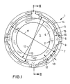
- FIG. 1 the supervision of an inventive, modular socket 1 shown. From the sliding shell 2 is the Sliding surface 3 and the end face 4 can be seen.
- the sliding shell 2 is a ring 5 surrounded by a biocompatible metal.
- the ring 5 points in the present Embodiment four evenly spaced around the circumference Fasteners 6 on.
- the fasteners 6 are in the Anchor socket 7 anchored. You reach there in appropriately shaped Recesses 8 ( Figure 3).
- the top view of the fastening elements 6 shows whose wedge shape widens outwards 9.
- the socket housing 7 has a wall thickness 10 corresponding to its design, which is between 2 mm and 5 mm can lie. With 11 is the inside diameter of the socket housing 7 for receiving referred to the sliding shell 2.
- this inner diameter is 11 much larger than the outer diameter 12 of the sliding shell 2. It is still larger than the outer diameter 13 of the ring 5. This creates between the Ring 5 and the socket housing 7, a gap 14.
- the fasteners 6 have so-called Spacer 15 on.
- the spacers 15, made of the same material as the ring 5 and the fastening elements 6 have a design similar to that of the socket housing 7 matched thickness 16, which corresponds to the desired gap width.
- the Spacers 15 not only serve to form the gap 14 evenly, but also ensure an even support of the ring 5 and thus the Sliding shell 2 in the pan housing 7.
- the outer diameter 12 of a sliding shell 2 with a Sliding surface 3 predetermined diameter for all types of a pan housing 7 constant.
- the difference is made by appropriate wall thicknesses 17 of the rings 5 between the inner diameter 11 of a socket housing 7 and the Outside diameter 12 of a sliding shell 2 balanced, so that the respective gap 14, which corresponds to the dimensions 16 of the spacers 15 in width, at all types of pan housing is essentially the same size.
- the gap 14 has a width 16, which is based on the diameter of the sliding surface and the type of Pan housing 7 matched, is between about 1 mm and about 1.8 mm.
- the Wall thickness 17 of the rings 5 therefore ranges from approximately 2 mm to approximately 5 mm.
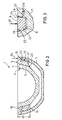
- FIG. 2 shows a section through the modular structure of the invention Joint socket 1 corresponding to the section II-II shown in FIG. 1.
- the cut runs through two opposite fasteners 6.
- the ring 5 encloses the sliding shell 2 in its outer Area 18, where conventional use of a sliding shell in a pan housing the socket is clamped.
- the connection between the ring 5 and the sliding shell 2 can be compared to the prior art by means of conical Clamping or shrinking.
- the height 19 of the ring 5 is in Similar to the conventional conical clamping in a socket housing, for example at 10 mm.
- To 5 voltages at the clamping of the sliding shell 2 in the ring Avoiding transition point 20 between ring 5 and sliding shell 2 tapers the ring 5 wedge-shaped 21 towards the sliding shell 2.
- the present embodiment shows how the ring 5 with its Spacers 15 abuts the socket housing 7. Furthermore, is under the Fastening element 6 to see a notch 22, in which, not shown here, gripper a tool can intervene to the ring 5 with the sliding shell 2 from the Lift out the pan housing 7.
- Figure 3 shows the engagement of a fastener 6 in the wall of the Pan housing 7. It is a sectional view in a further enlarged Scale.
- the fastening element 6 has a trapezoidal cross section 23 Recess 8, in which the fastening element 6 engages, has a cross section 23 of the fastener 6 adapted shape.
- the trapezoidal cross section 23 tapers in the direction 24 of the forces acting on the sliding shell 2 and the Meridians of the socket housing 7 (Fig. 2), which in the present embodiment has approximately the shape of a spherical zone.
- the force is introduced into the Pan housing 7 with a component 26 in the meridian direction 24 and with a Component 27 in a direction perpendicular thereto, corresponding to the Parallels.
- the side walls 25 are in the present embodiment at an angle to the meridians and the main direction of action of the forces 24 28 inclined by about 15 °.
- FIG. 4 shows a tool 30 with which one is embedded in a ring Sliding shell 2 inserted into a pan housing 7 or removed from it again can be.
- the representation of the tool 13 is purely schematic and is only intended to be explain its mode of action.
- the tool 30 has two components which can be displaced axially relative to one another, a support device 31 and a push and pull device 32, which have a Threaded spindle 33 are connected to each other, the support device 31 on a nut 34 is fastened, which is movably arranged on the threaded spindle 33, and the push and pull device 32 itself freely rotatable on the threaded spindle is attached.
- the support device 31 in the present exemplary embodiment consists of four supports 35 arranged parallel to one another and parallel to the threaded spindle 33 Columns 35 have the same size when viewed on the circumference of the nut 34 Angular distances. They are supported with feet 36 on the face of the Pan housing 7 from.
- An adjustment device not shown in detail here 37 enables the supports to be adapted to different diameters of the Pan housing 7. The adjustment can for example by loosening the here indicated screws and by moving the supports along Elongated holes are made according to the double arrow 38.
- the four supports 39 of the push and pull device 32 are in number and Arrangement matched to the fasteners 6 of the ring 5. You are rigid connected to each other via a ring 40 and in each case between the supports 35 of the Support device 31 arranged. The ring will turn freely at the end of the Threaded spindle 33 held between two washers 41.
- the supports 39 of the pressure and Traction device 32 are each placed on the fastening elements 6.
- the Supports 35 of the support device 31 are supported on the edge of the Pan housing 7 from.
- the toggle 42 By turning the toggle 42 at the top of the Screw spindle 33 clockwise 43, the supports 39 of the pressure and Traction device 32 in direction 44 and thus press the fasteners 6 in the recesses 8 of the socket housing 7. So that this indentation takes place can, the support 31 must also be pressed in the direction of arrow 44 be exercised.
- the hooks 45 articulated at the ends of the supports 39 to lift out the sliding shells are swiveled up so that they can push in Do not hinder sliding shell 2.
Landscapes
- Health & Medical Sciences (AREA)
- Orthopedic Medicine & Surgery (AREA)
- Transplantation (AREA)
- Heart & Thoracic Surgery (AREA)
- Cardiology (AREA)
- Oral & Maxillofacial Surgery (AREA)
- Engineering & Computer Science (AREA)
- Biomedical Technology (AREA)
- Vascular Medicine (AREA)
- Life Sciences & Earth Sciences (AREA)
- Animal Behavior & Ethology (AREA)
- General Health & Medical Sciences (AREA)
- Public Health (AREA)
- Veterinary Medicine (AREA)
- Physical Education & Sports Medicine (AREA)
- Prostheses (AREA)
Description
- Figur 1
- eine Aufsicht auf eine erfindungsgemäße, modular aufgebaute Gelenkpfanne,
- Figur 2
- einen Meridian-Schnitt durch die Gelenkpfanne, entsprechend dem Schnittverlauf in Figur 1,
- Figur 3
- als Einzelheit den Schnitt durch ein Befestigungselement in der Wand des Pfannengehäuses und
- Figur 4
- ein Werkzeug zur Handhabung von Gleitschalen.
Claims (11)
- Modular aufgebaute Gelenkpfanne für eine Kugelgelenk-Prothese zum Einsetzen in Knochengewebe, bestehend aus einer äußeren, in den Knochen einzusetzenden Metallschale als Pfannengehäuse (7) und eine in das Pfannengehäuse eingesetzte, innere Gleitschale (2) aus Keramik, wobei die Gleitschale (2) aus Keramik fest in einen Ring (5) aus einem biokompatiblen Metall eingesetzt ist, dadurch gekennzeichnet, daß der Ring (5) mit mindestens drei sich radial nach außen erstreckenden Befestigungselementen (6) besetzt ist, daß die Befestigungselemente (6) jeweils in eine Ausnehmung (8) in dem Pfannengehäuse (7) eingreifen und daß der Ring (5) von dem Pfannengehäuse (7) durch einen Spalt (14) beabstandet ist.
- Modular aufgebaute Gelenkpfanne nach Anspruch 1, dadurch gekennzeichnet, daß die Gleitschale (2) durch eine konische Klemmung in dem Ring (5) befestigt ist.
- Modular aufgebaute Gelenkpfanne nach Anspruch 1, dadurch gekennzeichnet, daß der Ring (5) auf die Gleitschale (2) aufgeschrumpft ist.
- Modular aufgebaute Gelenkpfanne nach einem der Ansprüche 1 bis 3, dadurch gekennzeichnet, daß zur Bildung eines Spalts (14) mit konstantem Abstand zwischen Gleitschale (2) und dem Pfannengehäuse (7) die Befestigungselemente (6) Abstandshalter (15) aufweisen.
- Modular aufgebaute Gelenkpfanne nach einem der Ansprüche 1 bis 4, dadurch gekennzeichnet, daß sich die Befestigungselemente (6) am Ring (5) in radialer Richtung keilförmig verbreitern (9) und daß die Ausnehmungen (8) in dem Pfannengehäuse (7) der Kontur der Befestigungselemente (6) angepaßt sind.
- Modular aufgebaute Gelenkpfanne nach einem der Ansprüche 1 bis 5, dadurch gekennzeichnet, daß die Befestigungselemente (6) sich in Richtung (24) des Einsetzens in das Pfannengehäuse (7) keilförmig verjüngen (23) und daß die Ausnehmungen (8) in dem Pfannengehäuse (7) der Kontur der Befestigungselemente (6) angepaßt sind.
- Modular aufgebaute Gelenkpfanne nach einem der Ansprüche 1 bis 6, dadurch gekennzeichnet, daß der Außendurchmesser (12) der Gleitschale (2) konstant ist und daß bei unterschiedlichen Innendurchmessern (11) des Pfannengehäuses (7) zur Aufnahme der Gleitschale (2) der Außendurchmesser (13) des Rings (5) dem Innendurchmesser (11) des Pfannengehäuses (7) so angepaßt ist, daß die Abmessungen des Spalts (14) bei den möglichen Kombinationen von Gleitschale (2) und Pfannengehäuse (7) stets in etwa gleich groß ist.
- Modular aufgebaute Gelenkpfanne nach einem der Ansprüche 1 bis 7, dadurch gekennzeichnet, daß ein Werkzeug (30) zur Handhabung der in einen Ring (5) eingesetzten Gleitschale (2) vorgesehen ist zum Einsetzen in das und Herausnehmen aus dem Pfannengehäuse (7)
- Modular aufgebaute Gelenkpfanne nach Anspruch 8, dadurch gekennzeichnet, daß das Werkzeug (30) zwei axial gegeneinander verschiebbare Komponenten (31, 32) aufweist, daß sich die erste Komponente als Abstützeinrichtung (31) auf dem Rand des Pfannengehäuses (7) abstützt und daß die zweite Komponente als Druck- und Zugeinrichtung (32), in Abhängigkeit der vorgesehenen Handhabung der Gleitschale (2), an den Befestigungselementen (6) der Gleitschale (2) positionierbar ist.
- Modular aufgebaute Gelenkpfanne nach Anspruch 9, dadurch gekennzeichnet, daß zum Einsetzen der Gleitschale (2) in das Pfannengehäuse (7) die Druckund Zugeinrichtung (32) auf die Befestigungselemente (6) und die Abstützeinrichtung (31) auf dem Rand des Pfannengehäuses (7) aufsetzbar sind und daß durch ein Verschieben der beiden Komponenten (31, 32) des Werkzeugs (30) voneinander weg auf die Gleitschale (2) eine Druckkraft in Richtung (44) des Pfannengehäuses (7) ausübbar ist.
- Modular aufgebaute Gelenkpfanne nach Anspruch 9, dadurch gekennzeichnet, daß zum Herauslösen einer Gleitschale (2) aus dem Pfannengehäuse (7) die Abstützeinrichtung (31) auf dem Rand des Pfannengehäuses (7) aufsetzbar ist und die Befestigungselemente (6) mittels der Druck- und Zugeinrichtung (32) hintergreifbar sind und daß durch Verschieben der beiden Komponenten (31, 32) des Werkzeugs (30) aufeinander zu die Gleitschale (2) aus dem Pfannengehäuse (7) heraushebbar ist.
Applications Claiming Priority (3)
| Application Number | Priority Date | Filing Date | Title |
|---|---|---|---|
| DE19926923 | 1999-06-14 | ||
| DE19926923A DE19926923A1 (de) | 1999-06-14 | 1999-06-14 | Modular aufgebaute Gelenkpfanne für eine Kugelgelenk-Prothese |
| PCT/EP2000/005427 WO2000076427A1 (de) | 1999-06-14 | 2000-06-13 | Modular aufgebaute gelenkpfanne für eine kugelgelenk-prothese |
Publications (2)
| Publication Number | Publication Date |
|---|---|
| EP1191907A1 EP1191907A1 (de) | 2002-04-03 |
| EP1191907B1 true EP1191907B1 (de) | 2004-09-15 |
Family
ID=7911085
Family Applications (1)
| Application Number | Title | Priority Date | Filing Date |
|---|---|---|---|
| EP00936878A Expired - Lifetime EP1191907B1 (de) | 1999-06-14 | 2000-06-13 | Modular aufgebaute gelenkpfanne für eine kugelgelenk-prothese |
Country Status (6)
| Country | Link |
|---|---|
| US (1) | US6589284B1 (de) |
| EP (1) | EP1191907B1 (de) |
| JP (1) | JP2003501204A (de) |
| AT (1) | ATE275892T1 (de) |
| DE (2) | DE19926923A1 (de) |
| WO (1) | WO2000076427A1 (de) |
Families Citing this family (46)
| Publication number | Priority date | Publication date | Assignee | Title |
|---|---|---|---|---|
| ATE387161T1 (de) | 2001-01-25 | 2008-03-15 | Smith & Nephew Inc | Rückhaltevorrichtung zum halten eines prosthetischen bestandteils |
| US20020120340A1 (en) | 2001-02-23 | 2002-08-29 | Metzger Robert G. | Knee joint prosthesis |
| US7497874B1 (en) | 2001-02-23 | 2009-03-03 | Biomet Manufacturing Corp. | Knee joint prosthesis |
| DE10149995A1 (de) * | 2001-10-11 | 2003-04-24 | Zf Lemfoerder Metallwaren Ag | Keramikkugelgelenk |
| DE20119715U1 (de) * | 2001-12-05 | 2002-02-21 | Aesculap AG & Co. KG, 78532 Tuttlingen | Endoprothetische Hüftgelenkpfanne |
| US6916342B2 (en) | 2002-04-01 | 2005-07-12 | Smith & Nephew, Inc. | Liner assembly for prosthetic components |
| US7344565B2 (en) * | 2003-02-04 | 2008-03-18 | Wright Medical Technology, Inc. | Acetabular component insertion and extraction tool for use therewith, and method of locking an acetabular component to an insertion and extraction tool |
| US7297166B2 (en) | 2003-06-25 | 2007-11-20 | Depuy Products, Inc. | Assembly tool for modular implants and associated method |
| US7582092B2 (en) | 2003-06-25 | 2009-09-01 | Depuy Products, Inc. | Assembly tool for modular implants and associated method |
| US8998919B2 (en) * | 2003-06-25 | 2015-04-07 | DePuy Synthes Products, LLC | Assembly tool for modular implants, kit and associated method |
| EP1570810B1 (de) * | 2004-02-25 | 2007-01-03 | Zimmer GmbH | Beckenteilendoprothese |
| AU2005221715B2 (en) | 2004-03-11 | 2011-09-22 | Smith & Nephew, Inc. | Universal liner assembly for joint replacement |
| GB0420348D0 (en) * | 2004-09-13 | 2004-10-13 | Finsbury Dev Ltd | Cap and activaton tool |
| US20060229731A1 (en) * | 2005-04-12 | 2006-10-12 | Zimmer Technology, Inc. | Acetabular implant with a tapered bearing-locking flange |
| US20060226570A1 (en) * | 2005-04-12 | 2006-10-12 | Zimmer Technology, Inc. | Method for making a metal-backed acetabular implant |
| US8147547B2 (en) * | 2005-04-29 | 2012-04-03 | Warsaw Orthopedic, Inc. | Spinal implant |
| US7976580B2 (en) * | 2005-08-18 | 2011-07-12 | Mayo Foundation For Medical Education And Research | Semi-constrained 1st carpometacarpal implant arthroplasty and method |
| US7708783B2 (en) * | 2005-11-04 | 2010-05-04 | Zimmer Technology, Inc. | Rotating constrained liner |
| US20070106392A1 (en) * | 2005-11-08 | 2007-05-10 | Howmedica Osteonics Corp. | Acetabular cup locking mechanism |
| US7727282B2 (en) | 2006-03-17 | 2010-06-01 | Biomet Manufacturing Corp. | Method and apparatus for implanting a prosthesis |
| CA2646061C (en) | 2006-03-20 | 2014-06-17 | Smith & Nephew, Inc. | Acetabular cup assembly for multiple bearing materials |
| US8308811B2 (en) * | 2006-04-11 | 2012-11-13 | Zimmer, Inc. | Acetabular cup conversion ring |
| US20070239283A1 (en) * | 2006-04-11 | 2007-10-11 | Berger Richard A | Acetabular cup conversion ring |
| DE102007031669A1 (de) * | 2006-08-04 | 2008-09-11 | Ceramtec Ag Innovative Ceramic Engineering | Asymmetrische Gestaltung von Hüftpfannen zur Verringerung der Pfannendeformationen |
| US8187280B2 (en) | 2007-10-10 | 2012-05-29 | Biomet Manufacturing Corp. | Knee joint prosthesis system and method for implantation |
| US8562616B2 (en) | 2007-10-10 | 2013-10-22 | Biomet Manufacturing, Llc | Knee joint prosthesis system and method for implantation |
| US8157869B2 (en) | 2007-01-10 | 2012-04-17 | Biomet Manufacturing Corp. | Knee joint prosthesis system and method for implantation |
| US8163028B2 (en) | 2007-01-10 | 2012-04-24 | Biomet Manufacturing Corp. | Knee joint prosthesis system and method for implantation |
| US8328873B2 (en) | 2007-01-10 | 2012-12-11 | Biomet Manufacturing Corp. | Knee joint prosthesis system and method for implantation |
| US8556912B2 (en) | 2007-10-30 | 2013-10-15 | DePuy Synthes Products, LLC | Taper disengagement tool |
| US8518050B2 (en) | 2007-10-31 | 2013-08-27 | DePuy Synthes Products, LLC | Modular taper assembly device |
| FR2935263B1 (fr) * | 2008-09-01 | 2012-02-24 | Denis Pichon | Cotyle prothetique articulaire. |
| EP2174621B1 (de) * | 2008-10-07 | 2013-07-17 | Finsbury (Development) Limited | Prothese |
| US8123815B2 (en) | 2008-11-24 | 2012-02-28 | Biomet Manufacturing Corp. | Multiple bearing acetabular prosthesis |
| DE102009054633A1 (de) * | 2008-12-17 | 2010-06-24 | Ceramtec Ag | Einsetzinstrument zum Einsetzen von Pfanneneinsätzen in die Kalotten von Hüftpfannen |
| DE102009031381B4 (de) * | 2009-04-14 | 2017-01-05 | Mathys Ag Bettlach | Modulare elastische Gelenkpfanne |
| US8308810B2 (en) | 2009-07-14 | 2012-11-13 | Biomet Manufacturing Corp. | Multiple bearing acetabular prosthesis |
| FR2950525B1 (fr) * | 2009-09-28 | 2013-05-10 | Thomas Gradel | Cotyle prothetique de hanche a fixation externe |
| US8533921B2 (en) | 2010-06-15 | 2013-09-17 | DePuy Synthes Products, LLC | Spiral assembly tool |
| FR2961387B1 (fr) * | 2010-06-17 | 2013-06-07 | Thomas Gradel | Cotyle ceramique a fixation externe |
| US9095452B2 (en) | 2010-09-01 | 2015-08-04 | DePuy Synthes Products, Inc. | Disassembly tool |
| CN103813764B (zh) | 2011-04-06 | 2017-04-19 | 德普伊新特斯产品有限责任公司 | 植入修正髋关节假体的器械组件和使用它的整形外科手术 |
| US9144496B2 (en) * | 2012-04-23 | 2015-09-29 | Zimmer, Inc. | Inserter connection member |
| EP3062748A1 (de) * | 2013-10-31 | 2016-09-07 | CeramTec GmbH | Instrumentarium zum trennen modularer keramischer hüftgelenksimplantate |
| GB201507211D0 (en) * | 2015-04-28 | 2015-06-10 | Depuy Ireland | Device and method for inserting a liner into an acetabular cup |
| EP3377782B1 (de) * | 2015-11-19 | 2020-05-06 | CeramTec GmbH | Ringförmiges keramisches insert für die endoprothetik |
Family Cites Families (35)
| Publication number | Priority date | Publication date | Assignee | Title |
|---|---|---|---|---|
| EP0091315B1 (de) | 1982-04-07 | 1986-07-30 | National Research Development Corporation | Gelenkendoprothese |
| US6042611A (en) * | 1983-03-08 | 2000-03-28 | Joint Medical Products Corporation | Ball and socket bearing for artificial joint |
| EP0142759A3 (de) * | 1983-11-22 | 1985-12-27 | Protek AG | Hüftgelenkpfanne |
| EP0253941B1 (de) * | 1986-07-09 | 1990-10-10 | CHENIL CONT S.p.A. | Gewichttragende Gelenkprothese mit Stossdämpfer |
| US5092897A (en) | 1990-03-15 | 1992-03-03 | Forte Mark R | Implantable acetabular prosthetic hip joint with universal adjustability |
| DE9014542U1 (de) * | 1990-10-20 | 1991-01-03 | Howmedica GmbH, 2314 Schönkirchen | Schalenelement zur Aufnahme einer Gelenkendoprothese |
| EP0551794B1 (de) * | 1992-01-16 | 1996-01-24 | SULZER Medizinaltechnik AG | Zweiteilige Hüftgelenkpfanne |
| US5551871A (en) * | 1993-03-05 | 1996-09-03 | Besselink; Petrus A. | Temperature-sensitive medical/dental apparatus |
| FR2706284B1 (fr) * | 1993-06-17 | 1995-09-29 | Roux Christiane | Prothèse cotyloïdienne, notamment pour articulation coxo-fémorale. |
| US5480448A (en) * | 1993-09-20 | 1996-01-02 | Mikhail; W. E. Michael | Acetabular cup groove insert |
| DE4335931B4 (de) * | 1993-10-21 | 2006-10-12 | Cerasiv Gmbh Innovatives Keramik-Engineering | Hüftgelenkpfanne |
| DE4402675A1 (de) * | 1993-11-26 | 1995-06-01 | Cerasiv Gmbh | Konische Hüftgelenkpfanne ohne Selbsthemmung |
| CH687436A5 (de) * | 1994-07-28 | 1996-12-13 | Werner Hermann | Pfannenteil einer Hueftgelenks-Prothese. |
| US5766260A (en) * | 1995-06-06 | 1998-06-16 | Whiteside; Leo A. | Acetabular component with improved liner seal and lock |
| US5658338A (en) | 1995-09-29 | 1997-08-19 | Tullos; Hugh S. | Prosthetic modular bone fixation mantle and implant system |
| DE29517637U1 (de) * | 1995-11-07 | 1996-01-04 | Aesculap AG & Co. KG, 78532 Tuttlingen | Endoprothetische Hüftgelenkpfanne |
| DE19611249A1 (de) * | 1996-03-22 | 1997-09-25 | Cerasiv Gmbh | Kombination aus einer Gelenkprothese und einem Ausziehwerkzeug |
| DE19616059A1 (de) * | 1996-04-23 | 1997-10-30 | Cerasiv Gmbh | Verfahren zum Erneuern einer prothetischen Gelenkpfanne |
| FR2748654B1 (fr) * | 1996-05-14 | 1998-11-20 | Setiey Louis | Implant cotyloidien fixe sans ciment |
| US6013082A (en) * | 1996-06-07 | 2000-01-11 | Johnson & Johnson Professional, Inc. | Extraction device |
| US5725591A (en) | 1996-08-13 | 1998-03-10 | Johnson & Johnson Professional, Inc. | Acetabular bearing system |
| DE19654106A1 (de) * | 1996-12-23 | 1998-07-02 | Man Ceramics Gmbh | Mehrteiliges Implantat |
| DE19654409C5 (de) * | 1996-12-24 | 2004-04-29 | Ceramtec Ag Innovative Ceramic Engineering | Hüftgelenkpfanne |
| DE29703857U1 (de) * | 1997-03-03 | 1997-05-07 | Aesculap Ag, 78532 Tuttlingen | Chirurgisches Instrument |
| US6022357A (en) * | 1997-03-03 | 2000-02-08 | Aesculap Ag & Co. Kg | Surgical instrument |
| EP0888759B1 (de) * | 1997-07-04 | 2003-01-02 | Sulzer Orthopädie AG | Instrument zum Einbringen eines Einsatzes eines Implantats in die zugehörige Schale |
| EP1032330A4 (de) * | 1997-10-31 | 2004-10-13 | Midwest Orthopedic Res Foundat | Hüftgelenkpfannen- prothese mit ausbreitung für ein mangelhaftes hüftgelenk |
| US6132469A (en) * | 1997-11-07 | 2000-10-17 | Biomet, Inc. | Acetabular liner extractor |
| US5904688A (en) * | 1997-12-30 | 1999-05-18 | Bristol-Myers Squibb Co. | Orthopaedic assembly including an acetabular cup and cup inserter |
| US5935175A (en) * | 1998-03-13 | 1999-08-10 | Johnson & Johnson Professional, Inc. | Acetabular prosthesis with ring lock mechanism |
| EP1076537B1 (de) * | 1998-04-30 | 2006-10-11 | CeramTec AG Innovative Ceramic Engineering | Instrument zur handhabung von komponenten von gelenkprothesen |
| CA2270861C (en) * | 1998-05-22 | 2006-08-29 | Michael B. Sheldon | Acetabular cup assembly with selected bearing |
| US6063123A (en) * | 1998-07-22 | 2000-05-16 | Sulzer Orthopedics Inc. | Acetabular insert extractor and method for use |
| US6063124A (en) * | 1999-03-01 | 2000-05-16 | Amstutz; Harlan C. | Acetabular cup prosthesis insertion and removal assembly and technique |
| US6488713B1 (en) * | 2001-04-25 | 2002-12-03 | Biomet, Inc. | Hip joint prosthesis with integral bearing extraction member |
-
1999
- 1999-06-14 DE DE19926923A patent/DE19926923A1/de not_active Withdrawn
-
2000
- 2000-06-13 WO PCT/EP2000/005427 patent/WO2000076427A1/de not_active Ceased
- 2000-06-13 EP EP00936878A patent/EP1191907B1/de not_active Expired - Lifetime
- 2000-06-13 DE DE50007794T patent/DE50007794D1/de not_active Expired - Fee Related
- 2000-06-13 AT AT00936878T patent/ATE275892T1/de not_active IP Right Cessation
- 2000-06-13 US US10/009,954 patent/US6589284B1/en not_active Expired - Fee Related
- 2000-06-13 JP JP2001502770A patent/JP2003501204A/ja active Pending
Also Published As
| Publication number | Publication date |
|---|---|
| ATE275892T1 (de) | 2004-10-15 |
| US6589284B1 (en) | 2003-07-08 |
| DE19926923A1 (de) | 2000-12-21 |
| DE50007794D1 (de) | 2004-10-21 |
| EP1191907A1 (de) | 2002-04-03 |
| JP2003501204A (ja) | 2003-01-14 |
| WO2000076427A1 (de) | 2000-12-21 |
Similar Documents
| Publication | Publication Date | Title |
|---|---|---|
| DE19926923A1 (de) | Modular aufgebaute Gelenkpfanne für eine Kugelgelenk-Prothese | |
| DE10065398C2 (de) | Längenverstellbarer Platzhalter zum Einsetzen zwischen zwei Wirbelkörper | |
| EP0904751B1 (de) | Rohrförmiger Stützkörper zum Überbrücken zweier Wirbel | |
| DE3027148C2 (de) | Einrichtung mit einer Platte und zu deren Befestigung an einem Knochen dienenden Schrauben | |
| DE60304489T2 (de) | Spannmutter für eine osteosynthesevorrichtung | |
| DE4435497C1 (de) | Modulares Knochenimplantat mit Pfanne und Stiften | |
| DE19841611B4 (de) | Implantierbare Prothese mit zumindest zwei gegeneinander verstellbaren Abschnitten sowie Verwendung verstellbarer Abschnitte | |
| EP0300131B1 (de) | Sattelprothese | |
| DE69109768T2 (de) | Protheseneinrichtung bestehend aus Hüftpfanne und Einschlaggerät. | |
| DE2646478C2 (de) | Gelenk-Endoprothese | |
| EP0694294B1 (de) | Pfannenteil einer Gelenkprothese | |
| EP0671151A1 (de) | Osteosynthesevorrichtung | |
| EP0614649A1 (de) | Knochenschraube | |
| DE2605644B2 (de) | Feststellbares Prothesengelenk | |
| WO1999039665A1 (de) | Platzhalter mit einstellbarer axialer länge | |
| EP1348388A1 (de) | Knochenverankerungsvorrichtung zum Stabilisieren von Knochensegmenten | |
| DE69009418T2 (de) | Prothetische Vorrichtung mit Modulschaft. | |
| DE2712855A1 (de) | Gelenk-endoprothese | |
| DE10039767B4 (de) | Befestigungsanordnung | |
| DE19616059A1 (de) | Verfahren zum Erneuern einer prothetischen Gelenkpfanne | |
| WO1986000011A1 (fr) | Tige de prothese de la hanche implantable | |
| EP1774927A1 (de) | Chirurgisches Instrument zum Entfernen eines Zwischenwirbelimplantats | |
| DE10014401C2 (de) | Abziehinstrument zum Lösen einzelner Teile einer Endoprothese | |
| DE29910113U1 (de) | Prothesenschaft | |
| DE4136313C2 (de) | Äußere axiale Fixiervorrichtung |
Legal Events
| Date | Code | Title | Description |
|---|---|---|---|
| PUAI | Public reference made under article 153(3) epc to a published international application that has entered the european phase |
Free format text: ORIGINAL CODE: 0009012 |
|
| 17P | Request for examination filed |
Effective date: 20020114 |
|
| AK | Designated contracting states |
Kind code of ref document: A1 Designated state(s): AT BE CH CY DE DK ES FI FR GB GR IE IT LI LU MC NL PT SE |
|
| GRAP | Despatch of communication of intention to grant a patent |
Free format text: ORIGINAL CODE: EPIDOSNIGR1 |
|
| GRAS | Grant fee paid |
Free format text: ORIGINAL CODE: EPIDOSNIGR3 |
|
| GRAA | (expected) grant |
Free format text: ORIGINAL CODE: 0009210 |
|
| AK | Designated contracting states |
Kind code of ref document: B1 Designated state(s): AT BE CH CY DE DK ES FI FR GB GR IE IT LI LU MC NL PT SE |
|
| PG25 | Lapsed in a contracting state [announced via postgrant information from national office to epo] |
Ref country code: NL Free format text: LAPSE BECAUSE OF FAILURE TO SUBMIT A TRANSLATION OF THE DESCRIPTION OR TO PAY THE FEE WITHIN THE PRESCRIBED TIME-LIMIT Effective date: 20040915 Ref country code: IT Free format text: LAPSE BECAUSE OF FAILURE TO SUBMIT A TRANSLATION OF THE DESCRIPTION OR TO PAY THE FEE WITHIN THE PRE;WARNING: LAPSES OF ITALIAN PATENTS WITH EFFECTIVE DATE BEFORE 2007 MAY HAVE OCCURRED AT ANY TIME BEFORE 2007. THE CORRECT EFFECTIVE DATE MAY BE DIFFERENT FROM THE ONE RECORDED.SCRIBED TIME-LIMIT Effective date: 20040915 Ref country code: IE Free format text: LAPSE BECAUSE OF FAILURE TO SUBMIT A TRANSLATION OF THE DESCRIPTION OR TO PAY THE FEE WITHIN THE PRESCRIBED TIME-LIMIT Effective date: 20040915 Ref country code: FI Free format text: LAPSE BECAUSE OF FAILURE TO SUBMIT A TRANSLATION OF THE DESCRIPTION OR TO PAY THE FEE WITHIN THE PRESCRIBED TIME-LIMIT Effective date: 20040915 |
|
| REG | Reference to a national code |
Ref country code: GB Ref legal event code: FG4D Free format text: NOT ENGLISH Ref country code: CH Ref legal event code: EP |
|
| REG | Reference to a national code |
Ref country code: IE Ref legal event code: FG4D Free format text: GERMAN |
|
| REF | Corresponds to: |
Ref document number: 50007794 Country of ref document: DE Date of ref document: 20041021 Kind code of ref document: P |
|
| REG | Reference to a national code |
Ref country code: CH Ref legal event code: NV Representative=s name: ISLER & PEDRAZZINI AG |
|
| PG25 | Lapsed in a contracting state [announced via postgrant information from national office to epo] |
Ref country code: SE Free format text: LAPSE BECAUSE OF FAILURE TO SUBMIT A TRANSLATION OF THE DESCRIPTION OR TO PAY THE FEE WITHIN THE PRESCRIBED TIME-LIMIT Effective date: 20041215 Ref country code: GR Free format text: LAPSE BECAUSE OF FAILURE TO SUBMIT A TRANSLATION OF THE DESCRIPTION OR TO PAY THE FEE WITHIN THE PRESCRIBED TIME-LIMIT Effective date: 20041215 Ref country code: DK Free format text: LAPSE BECAUSE OF FAILURE TO SUBMIT A TRANSLATION OF THE DESCRIPTION OR TO PAY THE FEE WITHIN THE PRESCRIBED TIME-LIMIT Effective date: 20041215 |
|
| PG25 | Lapsed in a contracting state [announced via postgrant information from national office to epo] |
Ref country code: ES Free format text: LAPSE BECAUSE OF FAILURE TO SUBMIT A TRANSLATION OF THE DESCRIPTION OR TO PAY THE FEE WITHIN THE PRESCRIBED TIME-LIMIT Effective date: 20041226 |
|
| GBT | Gb: translation of ep patent filed (gb section 77(6)(a)/1977) |
Effective date: 20050117 |
|
| NLV1 | Nl: lapsed or annulled due to failure to fulfill the requirements of art. 29p and 29m of the patents act | ||
| REG | Reference to a national code |
Ref country code: IE Ref legal event code: FD4D |
|
| PG25 | Lapsed in a contracting state [announced via postgrant information from national office to epo] |
Ref country code: LU Free format text: LAPSE BECAUSE OF NON-PAYMENT OF DUE FEES Effective date: 20050613 Ref country code: CY Free format text: LAPSE BECAUSE OF FAILURE TO SUBMIT A TRANSLATION OF THE DESCRIPTION OR TO PAY THE FEE WITHIN THE PRESCRIBED TIME-LIMIT Effective date: 20050613 Ref country code: AT Free format text: LAPSE BECAUSE OF NON-PAYMENT OF DUE FEES Effective date: 20050613 |
|
| PG25 | Lapsed in a contracting state [announced via postgrant information from national office to epo] |
Ref country code: MC Free format text: LAPSE BECAUSE OF NON-PAYMENT OF DUE FEES Effective date: 20050630 Ref country code: BE Free format text: LAPSE BECAUSE OF NON-PAYMENT OF DUE FEES Effective date: 20050630 |
|
| ET | Fr: translation filed | ||
| PLBE | No opposition filed within time limit |
Free format text: ORIGINAL CODE: 0009261 |
|
| STAA | Information on the status of an ep patent application or granted ep patent |
Free format text: STATUS: NO OPPOSITION FILED WITHIN TIME LIMIT |
|
| 26N | No opposition filed |
Effective date: 20050616 |
|
| PGFP | Annual fee paid to national office [announced via postgrant information from national office to epo] |
Ref country code: GB Payment date: 20060615 Year of fee payment: 7 Ref country code: CH Payment date: 20060615 Year of fee payment: 7 |
|
| PGFP | Annual fee paid to national office [announced via postgrant information from national office to epo] |
Ref country code: FR Payment date: 20060619 Year of fee payment: 7 |
|
| PGFP | Annual fee paid to national office [announced via postgrant information from national office to epo] |
Ref country code: DE Payment date: 20060830 Year of fee payment: 7 |
|
| REG | Reference to a national code |
Ref country code: CH Ref legal event code: PCAR Free format text: ISLER & PEDRAZZINI AG;POSTFACH 1772;8027 ZUERICH (CH) |
|
| BERE | Be: lapsed |
Owner name: *CERAMTEC A.G. INNOVATIVE CERAMIC ENGINEERING Effective date: 20050630 |
|
| PG25 | Lapsed in a contracting state [announced via postgrant information from national office to epo] |
Ref country code: PT Free format text: LAPSE BECAUSE OF NON-PAYMENT OF DUE FEES Effective date: 20050215 |
|
| REG | Reference to a national code |
Ref country code: CH Ref legal event code: PL |
|
| GBPC | Gb: european patent ceased through non-payment of renewal fee |
Effective date: 20070613 |
|
| REG | Reference to a national code |
Ref country code: FR Ref legal event code: ST Effective date: 20080229 |
|
| PG25 | Lapsed in a contracting state [announced via postgrant information from national office to epo] |
Ref country code: LI Free format text: LAPSE BECAUSE OF NON-PAYMENT OF DUE FEES Effective date: 20070630 Ref country code: DE Free format text: LAPSE BECAUSE OF NON-PAYMENT OF DUE FEES Effective date: 20080101 Ref country code: CH Free format text: LAPSE BECAUSE OF NON-PAYMENT OF DUE FEES Effective date: 20070630 |
|
| PG25 | Lapsed in a contracting state [announced via postgrant information from national office to epo] |
Ref country code: GB Free format text: LAPSE BECAUSE OF NON-PAYMENT OF DUE FEES Effective date: 20070613 |
|
| PG25 | Lapsed in a contracting state [announced via postgrant information from national office to epo] |
Ref country code: FR Free format text: LAPSE BECAUSE OF NON-PAYMENT OF DUE FEES Effective date: 20070702 |