EP1191689A2 - Method and apparatus for adjusting reference frequency - Google Patents
Method and apparatus for adjusting reference frequency Download PDFInfo
- Publication number
- EP1191689A2 EP1191689A2 EP01122459A EP01122459A EP1191689A2 EP 1191689 A2 EP1191689 A2 EP 1191689A2 EP 01122459 A EP01122459 A EP 01122459A EP 01122459 A EP01122459 A EP 01122459A EP 1191689 A2 EP1191689 A2 EP 1191689A2
- Authority
- EP
- European Patent Office
- Prior art keywords
- frequency
- correlation value
- peak
- peak correlation
- adjusting
- Prior art date
- Legal status (The legal status is an assumption and is not a legal conclusion. Google has not performed a legal analysis and makes no representation as to the accuracy of the status listed.)
- Granted
Links
Images


Classifications
-
- H—ELECTRICITY
- H04—ELECTRIC COMMUNICATION TECHNIQUE
- H04B—TRANSMISSION
- H04B1/00—Details of transmission systems, not covered by a single one of groups H04B3/00 - H04B13/00; Details of transmission systems not characterised by the medium used for transmission
- H04B1/69—Spread spectrum techniques
- H04B1/707—Spread spectrum techniques using direct sequence modulation
- H04B1/7073—Synchronisation aspects
- H04B1/7087—Carrier synchronisation aspects
-
- H—ELECTRICITY
- H03—ELECTRONIC CIRCUITRY
- H03J—TUNING RESONANT CIRCUITS; SELECTING RESONANT CIRCUITS
- H03J7/00—Automatic frequency control; Automatic scanning over a band of frequencies
- H03J7/02—Automatic frequency control
- H03J7/04—Automatic frequency control where the frequency control is accomplished by varying the electrical characteristics of a non-mechanically adjustable element or where the nature of the frequency controlling element is not significant
Definitions
- the present invention relates to a method and apparatus for adjusting reference frequency in receiver and storage medium storing control program therefor, and in particular so as to remove reference oscillator frequency offset in a telecommunications receiver and, in particular, in a mobile telephone receiver operating in a cellular transmission system.
- the timing and frequency accuracy of transmissions from network base stations rely on very stable and highly accurate reference oscillators.
- the reference oscillators and the network base stations can be relatively expensive and accurate.
- An accuracy of e.g., 0.05 parts per million (ppm) is typical and more accurate oscillators are available.
- ppm parts per million
- these systems there are typically far more mobile stations which communicate with the network base stations.
- a system such as UMTS these are mobile telephones which have to be sold at a competitive market price and therefore costs have to be minimised. Therefore, low cost reference oscillators such as voltage control crystal oscillators (VCXO) would usually be selected for the reference oscillators of mobile stations.
- the frequency accuracy of these low cost reference oscillators is relatively low, e.g., 5 ppm.
- a method for adjusting reference frequency in a receiver wherein received signals include a plurality of sequential slots of data, at least one of which includes synchronization data, the method including the steps of down-converting received signals using a first frequency derived from a local oscillator, performing a correlation of down-converted signal with the locally stored synchronization code, detecting a peak correlation value from the result of the correlation, comparing the peak correlation value with the contents of a peak correlation value store, and adjusting the frequency applied to the down-converting in dependence on the results of the comparison, wherein further correlations and further frequency adjustments are repeatedly performed to adjust the reference frequency also in dependence on the results of the comparison.
- a preferable mode is one wherein the frequency adjustments comprise predetermined frequency steps and adjustments continue to be applied if the peak correlation value detected is larger than the contents of the peak correlation value store.
- a preferable mode is one wherein further including the step of removing the last made frequency adjustment if it results in a smaller peak correlation value than is in the peak correlation value store.
- a preferable mode is one wherein further including the step of subsequently applying a smaller frequency adjustment and performing further correlations and frequency adjustments with this step if it results in a larger peak correlation value than the contents of the peak correlation value store.
- a preferable mode is one wherein further smaller frequency adjustments are applied in response to a peak correlation value being detected which is smaller than is in the peak correlation value store after removal of the previous frequency adjustment.
- an apparatus for adjusting reference frequency in a receiver wherein received signals include a plurality of sequential slots of data, at least one of which includes synchronization data including means for down-converting received signals using a first frequency derived from a local oscillator, means for performing a correlation of the down-converted data with the locally stored synchronization code, means for detecting a peak correlation value, means for comparing the peak correlation value with the contents of a peak correlation value store, means for adjusting the frequency applied to the down-converting in dependence on the result of the comparison, means for performing further correlations and further frequency adjustments also in dependence on the result of the comparison.
- a preferable mode is one wherein the frequency adjustments applied by the means for adjusting the frequency comprise predetermined frequency steps and adjustments continue to be applied so long as the peak correlation value detected is larger than the content of the peak correlation value store.
- a preferable mode is one wherein the means for adjusting the frequency applied to the down-converter comprises means for removing the last made frequency adjustment if it resulted in a smaller peak correlation value than is stored in the peak correlation value store.
- a preferable mode is one wherein the means for adjusting the frequency applies a smaller frequency adjustment and performs further correlations and frequency adjustments with this step if it results in a larger peak correlation value than is stored in the peak correlation value store.
- a preferable mode is one wherein the means for adjusting the frequency applies further smaller frequency adjustments in response to a peak correlation value being detected which is smaller than is in the peak correlation value store after removal of the previous frequency adjustment.
- a storage medium storing a control program to cause a computer to carry out a method for adjusting reference frequency in a receiver wherein received signals include a plurality of sequential slots of data, at least one of which includes synchronization data, said method including a step of down-converting received signals using a first frequency derived from a local oscillator, a step of performing a correlation of the down-converted signal with the locally stored synchronization code; a step of detecting a peak correlation value, a step of comparing the peak correlation value with the contents of a peak correlation value store, a step of adjusting the frequency applied to the down-converting in dependence on the results of the comparison, and a step of performing further correlations and further frequency adjustment also in dependence on the results of the comparison.
- base stations which transmit and receive signals to mobile stations are asynchronous. Transmissions from the base stations need to be synchronized locally by mobiles which receive them. This is performed in an initial cell search when a mobile unit has power applied to it.
- UMTS transmissions comprise a sequence of frames. Each of these has, e.g., 15 slots and contained within each of these is information dependent on the data rate to be used. Each slot contains a number of symbols where each symbol comprises 2 bits. These 2 bits can be used to transmit 4 possible states using quadrature phase shift keying. Therefore, a 10 symbol slot comprises 20 bits.
- Base station transmissions include a synchronization channel (SCH) which is aligned with a slot boundary and a primary common control physical channel (PCCPCH). There are 10 symbol slots in these channels
- the synchronization channel comprises a primary synchronization code (PSC) and a secondary synchronization code (SSC) as illustrated in Figure 2. These are used in the initial cell search.
- PSC primary synchronization code
- SSC secondary synchronization code
- FIG. 1 illustrates schematically base station broadcast transmissions which are represented at 1, a transmission channel at 2, and a mobile station receiver at 3. In this example, transmissions from two base stations (BTS1 and BTS2) are shown.
- the base station transmissions are not synchronized with each other and transmit frames comprising slots and symbols as described above.
- the time intervals for slots and frames are fixed.
- the transmissions from the base stations BTS1 and BTS2 to the receiver 3 will be affected by channel 2.
- Transmissions from BTS2 are illustrated as being received through a 3-path (multipath) channel while the transmissions of BTS1 are illustrated as being received through a 2-path channel.
- the effect of the channel 2 is to pass the signals from BTS1 and BTS2 to the receiver 3 where they are summed.
- Correlation of the received signal by the mobile receiver with the expected primary synchronization code stored in the receiver then provides a number of correlation peaks. The highest peak detected corresponds to the base station of the network to which the receiver will synchronize.
- Correlation is performed on one slot and the results are held in a buffer. The results for a number of slots are added in. Noise and interference should be reduced and correlation will be the peak if any are detected.
- the second step of the initial cell search establishes frame synchronization and identifies the code group of the base station found in step 1.
- the third step of the initial cell search determines the scrambling code assigned to the found base station. Further details of these second and third steps are not pertinent to the present invention and are therefore not discussed further here but will be known to those skilled in the art.
- the exact frequency to which the received signal is down-converted may not be exactly the same as that at the transmitter because of inaccuracies in the local oscillator which arises because, as described above, it is lower in cost than that used at the base station. If there is a frequency offset, then the height of correlation peak will be reduced. If the offset is significant then the correlation peak may get buried in the noise and interference therefore making it impossible to synchronize to the slot boundaries.
- the performance of the UMTS cell search when operating in the FDD (Frequency Division Duplex) mode can be degraded by offsets in the carrier and sampling clock frequencies f c and f smp . These are both derived from the frequency of a reference oscillator f x in the mobile unit.
- a desired carrier frequency of 2 GHz in a sampling clock frequency of 15.36MHz with an inaccuracy of 1 ppm in reference frequency represents an offset of 2 KHz in the carrier frequency and 15.36 Hz in the sampling frequency.
- WCDMA wideband code division multiple access
- Phase rotation caused by the offsets in the carrier frequency results in a decrease in the received signal to noise plus interference ratio and consequently to an increase in the probability of false detection of timing instances (slot boundaries).
- Large values of carrier frequency offset can result in large reductions in the received signal power.
- the sharp reduction in the probability of success of the UMTS cell search process is amongst the negative effects of the large carrier frequency offsets.
- sampling clock offsets may cause slot boundaries to be detected in the wrong place. If the error in locating the slot boundaries is larger than one chip period (1/3.84 ⁇ s), the results obtained by the remaining cell search steps will also be in error. However, for practical frequency inaccuracies, the one chip error caused by the sampling clock inaccuracies is observed over long time intervals. Consequently, these inaccuracies are of secondary importance compared to the offsets in the carrier frequency. We have appreciated that the effects of these may be observed immediately and can be used to offset the referencing frequency nearer to its desired value. The consequent reduction in the inaccuracy of the reference frequency will also reduce the offsets in the carrier and sampling clock frequencies.
- Preferred embodiments of the present invention provide a method and apparatus for removal of carrier frequency offsets by iterative stepping of the IF/RF local oscillators and frequency.
- the implementation of the invention described herein is applicable to the initial cell search performed at a mobile station operating in frequency division duplex (FDD) mode in a UMTS network.
- the performance of the UMTS cell search can be degraded by offsets in the carrier and sampling clock frequencies .
- both the carrier and sampling clock frequencies are derived from the frequency of a reference oscillator (usually a VCXO).
- the carrier (f c ) and the sampling clock frequencies (f smp ) may be expressed as in equations (1) and (2) respectively.
- the terms k 1 and k 2 in these equations represent constants and f x is the reference frequency supplied by the reference oscillator of the mobile station.
- Equations (1) and (2) indicate the ways in which inaccuracies in the reference frequency generated by the crystal oscillator translate into the inaccuracies in the carrier and sampling clock frequencies. When expressed in parts per million, the same inaccuracy will apply to each of the three frequencies, f x , f c and f smp . For example, for a desired carrier frequency of 2GHz, and a sampling clock frequency of 15.36 MHz, an inaccuracy of 1 ppm (in f x ) represents offsets of 2kHz in the carrier frequency and 15.36 Hz in the sampling frequency.
- the in phase (I) and quadrature (Q) components of the received signal are correlated with the primary synchronization code.
- T the correlation period.
- Equation (5) represents the correlation between the local primary synchronization code and the received signal at the slot boundaries.
- the primary synchronization code is a known signal
- the carrier frequency offset may be estimated by measuring the change in the phase of the received primary synchronization code. Ignoring the effect Doppler and noise plus interference for simplicity, equation 5 may be reduced to The correlation peak is then found by finding the power of the above integral.
- M 2 1 and then the following relationship expresses the correlation power:
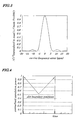
- the graphical plot of Figure 3 is derived from equation 7 and shows the value of correlation power versus the carrier frequency offset (in ppm) for correlation periods of 1 PSC (256 chips in FDD mode of UMTS).
- the plot shows the received signal power as a function of carrier frequency offset.
- the effect of carrier frequency offset on the received correlation peak power is shown in Figures 4, 5 and 6 for a stationary mobile. More specifically, Fig. 4 illustrates the result of a full correlation with no frequency offset, Fig. 5 shows the results from a full correlation at a frequency offset of 5 ppm, and Fig. 6 shows the results from a full correlation at a frequency offset of 7.5 ppm.
- the size of carrier frequency offset may be estimated by detecting its effect on the correlation between the received PSC signal and the local PSC at the mobile receiver. As it was shown before, the larger values of the carrier frequency offset correspond to smaller values of the correlation power.
- the correlation process is applied per slot of the received signal and may be averaged to provide a set of average correlation powers by processing a number of received slots. The largest average power, corresponding to the largest average peak is selected and saved as reference.
- the carrier frequency is changed by the addition of a frequency shift, selected from a set of predetermined frequencies under software control.
- the process of correlation power measurement is then applied to the next set of received signal slots to choose a further average power corresponding to the largest peak is better than the previously stored reference, then the frequency shift is kept and the reference is replaced by the new correlation power.
- the addition of the last frequency shift is undone and instead a smaller value of the frequency shift is applied to the carrier frequency. The process continues until all of the available shifts have been used. The shift corresponding to the stored reference then becomes the offset to be applied.
- the frequency shifts applied decrease in size with each next smaller frequency shift being applied when the application of a larger one resulted in a degradation in power.
- the software will activate the UMTS cell search process to enable the mobile to lock-on to a transmitter in a cell.
- step S2 data capture
- step S4 a full correlation of the received PCCPCH signal and the local PSC is performed at the mobile receiver
- step S6 This may be performed over a number of slots and the results averaged before passing to the peak selection step (step S6) which selects the largest peak.
- step S8 After peak selection the time position of the largest peak is set as the reference peak in step S8. The iterative progress then begins.
- the reference frequency is increased by a predetermined step length (step S10).
- the step length used depends on the inaccuracy of the reference oscillator and the desired measurement duration. For instance for an inaccuracy of say 5 ppm, 4 steps of -5, -2.5, +2.5, and +5 maybe used. If better resolution is needed, the step size may be reduced by increasing the number of steps. It is also possible to use step sizes which are not all a multiple of the minimum step, e.g., -5, -3, +3, and +5.
- the first reference frequency step is the largest step that will be applied and the other stored possible steps are all smaller. Typically, step length will decrease by 50% successively.
- step S12 data capture is performed in step S12, a full correlation performed in step S14, and the peak selected in step S16.
- Reference modification is applied in step S18 if the new peak is larger than the previous peak and then in step S20 the frequency step applied to the reference frequency in step S16 is either kept removed in dependence on whether or not any improvement to the reference peak was made in step S18.
- FIG. 8 A block diagram of a circuit for performing the method of Figure 7 is shown in Figure 8.
- RF/IF signals are received via an antenna 30 which supplied them to a down-converter 32. This down-converts them in dependence on the frequency supplied by a local oscillator 34 multiplied in a multiplier 36 by a constant K 1 .
- the signals are sampled for data capture in a sampling unit 38.
- the timing of samples is controlled by a sampling frequency supplied by the local oscillator 34 after multiplication by constant K 2 in multiplier 40.
- the sample signals are correlated with a locally stored primary synchronization code PSC from a memory 42 in a correlator 44. This may perform a single correlation or may perform a succession of correlations which are averaged.
- the results from the correlation are supplied to a peak selector 46 which detects the largest correlation peak. Initially, this is stored in a reference store 48 whose contents are initially empty. This occurs because the peak is also supplied to a peak comparator 50 which compares the size of the peak with the size of any peak stored in the reference store 48 and, if the result of the comparison is that the current peak is larger, it causes the contents of the reference stored to be overwritten with the new peak.
- a frequency stepping unit 52 then operates to adjust the local oscillator 34. Sampling, correlation, peak selection and peak comparison are then performed again and the reference store updated again if the new peak is larger than the previous peak. This continues with decreasing step sizes applied by the frequency stepper 52 until all frequency steps all frequency steps have been cycled through. When this occurs, the frequency stepper 52 applies a control signal to a cell search unit 54 to continue the process of locking on to a cell base station so that the mobile phone is ready to receive and transmit calls. This further cell search does not form part of the subject matter of the present application.
- a mobile receiver as described in the above embodiments has a processor (not shown) to control each of components of the mobile receiver in accordance with a specified control program, a ROM (not shown) used to store the specified control program executed by the processor, a RAM (not shown) serving as a working area of the processor or the like.
Abstract
Description
- The present invention relates to a method and apparatus for adjusting reference frequency in receiver and storage medium storing control program therefor, and in particular so as to remove reference oscillator frequency offset in a telecommunications receiver and, in particular, in a mobile telephone receiver operating in a cellular transmission system.
- In cellular communication systems, the timing and frequency accuracy of transmissions from network base stations rely on very stable and highly accurate reference oscillators. As there are a fixed and relatively small number of network base stations in a system such as universal mobile telecommunications system (UMTS), or any other mobile phone system, the reference oscillators and the network base stations can be relatively expensive and accurate. An accuracy of e.g., 0.05 parts per million (ppm) is typical and more accurate oscillators are available. In such systems, however, there are typically far more mobile stations which communicate with the network base stations. In a system such as UMTS, these are mobile telephones which have to be sold at a competitive market price and therefore costs have to be minimised. Therefore, low cost reference oscillators such as voltage control crystal oscillators (VCXO) would usually be selected for the reference oscillators of mobile stations. The frequency accuracy of these low cost reference oscillators is relatively low, e.g., 5 ppm.
- Because the accuracy of the mobile oscillators is much less than that available to the base stations with their more accurate reference oscillators, significant problems can occur with synchronization between the base station transmission and the locally generated carrier frequency used for down conversion.
- In view of the above, it is an object of the present invention to provide a method and apparatus for adjusting reference frequency in a receiver and storage medium storing control program therefor, specifically a method and apparatus for removing reference frequency offset of a local oscillator in a telecommunications receiver and storage medium storing control program therefor.
- According to a first aspect of the present invention, there is provided a method for adjusting reference frequency in a receiver wherein received signals include a plurality of sequential slots of data, at least one of which includes synchronization data, the method including the steps of down-converting received signals using a first frequency derived from a local oscillator, performing a correlation of down-converted signal with the locally stored synchronization code, detecting a peak correlation value from the result of the correlation, comparing the peak correlation value with the contents of a peak correlation value store, and adjusting the frequency applied to the down-converting in dependence on the results of the comparison, wherein further correlations and further frequency adjustments are repeatedly performed to adjust the reference frequency also in dependence on the results of the comparison.
- In the foregoing, a preferable mode is one wherein the frequency adjustments comprise predetermined frequency steps and adjustments continue to be applied if the peak correlation value detected is larger than the contents of the peak correlation value store.
- Also, a preferable mode is one wherein further including the step of removing the last made frequency adjustment if it results in a smaller peak correlation value than is in the peak correlation value store.
- Also, a preferable mode is one wherein further including the step of subsequently applying a smaller frequency adjustment and performing further correlations and frequency adjustments with this step if it results in a larger peak correlation value than the contents of the peak correlation value store.
- Also, a preferable mode is one wherein further smaller frequency adjustments are applied in response to a peak correlation value being detected which is smaller than is in the peak correlation value store after removal of the previous frequency adjustment.
- According to a second aspect of the present invention, there is provided an apparatus for adjusting reference frequency in a receiver wherein received signals include a plurality of sequential slots of data, at least one of which includes synchronization data, the apparatus including means for down-converting received signals using a first frequency derived from a local oscillator, means for performing a correlation of the down-converted data with the locally stored synchronization code, means for detecting a peak correlation value, means for comparing the peak correlation value with the contents of a peak correlation value store, means for adjusting the frequency applied to the down-converting in dependence on the result of the comparison, means for performing further correlations and further frequency adjustments also in dependence on the result of the comparison.
- In the foregoing, a preferable mode is one wherein the frequency adjustments applied by the means for adjusting the frequency comprise predetermined frequency steps and adjustments continue to be applied so long as the peak correlation value detected is larger than the content of the peak correlation value store.
- Also, a preferable mode is one wherein the means for adjusting the frequency applied to the down-converter comprises means for removing the last made frequency adjustment if it resulted in a smaller peak correlation value than is stored in the peak correlation value store.
- Also, a preferable mode is one wherein the means for adjusting the frequency applies a smaller frequency adjustment and performs further correlations and frequency adjustments with this step if it results in a larger peak correlation value than is stored in the peak correlation value store.
- Also, a preferable mode is one wherein the means for adjusting the frequency applies further smaller frequency adjustments in response to a peak correlation value being detected which is smaller than is in the peak correlation value store after removal of the previous frequency adjustment.
- According to a third aspect of the present invention, there is provided a storage medium storing a control program to cause a computer to carry out a method for adjusting reference frequency in a receiver wherein received signals include a plurality of sequential slots of data, at least one of which includes synchronization data, said method including a step of down-converting received signals using a first frequency derived from a local oscillator, a step of performing a correlation of the down-converted signal with the locally stored synchronization code; a step of detecting a peak correlation value, a step of comparing the peak correlation value with the contents of a peak correlation value store, a step of adjusting the frequency applied to the down-converting in dependence on the results of the comparison, and a step of performing further correlations and further frequency adjustment also in dependence on the results of the comparison.
- The above and other objects, advantages, and features of the present invention will be more apparent from the following description taken in conjunction with the accompanying drawings in which:
- Fig. 1 is a schematic illustration of base station transmissions to a receiver;
- Fig. 2 illustrates the composition of base station transmissions;
- Fig. 3 is a plot of normalized correlation power versus frequency offset;
- Fig. 4 illustrates the result of a full correlation with no frequency offset;
- Fig. 5 shows the results from a full correlation at a frequency offset of 5 ppm.
- Fig. 6 shows the results from a full correlation at a frequency offset of 7.5 ppm;
- Fig. 7 is a flowchart illustrating the frequency correction process; and
- Fig. 8 shows a block diagram of a system for implementing the process of Figure 7.
-
- Best modes of carrying out the present invention will be described in further detail using various embodiments with reference to the accompanying drawings.
- The problems discussed above and the solution provided by embodiments of the invention is described with reference to UMTS. It is, however, not limited to this transmission standard and can be applied to any WCDMA systems.
- In UMTS, base stations which transmit and receive signals to mobile stations are asynchronous. Transmissions from the base stations need to be synchronized locally by mobiles which receive them. This is performed in an initial cell search when a mobile unit has power applied to it.
- UMTS transmissions comprise a sequence of frames. Each of these has, e.g., 15 slots and contained within each of these is information dependent on the data rate to be used. Each slot contains a number of symbols where each symbol comprises 2 bits. These 2 bits can be used to transmit 4 possible states using quadrature phase shift keying. Therefore, a 10 symbol slot comprises 20 bits.
- Base station transmissions include a synchronization channel (SCH) which is aligned with a slot boundary and a primary common control physical channel (PCCPCH). There are 10 symbol slots in these channels The synchronization channel comprises a primary synchronization code (PSC) and a secondary synchronization code (SSC) as illustrated in Figure 2. These are used in the initial cell search.
- Initial cell search by a mobile station is performed in three steps. The first of these is the acquisition of slot synchronization to the transmissions of the base station providing the strongest signal at the receiver of a mobile station. Figure 1 illustrates schematically base station broadcast transmissions which are represented at 1, a transmission channel at 2, and a mobile station receiver at 3. In this example, transmissions from two base stations (BTS1 and BTS2) are shown.
- The base station transmissions are not synchronized with each other and transmit frames comprising slots and symbols as described above. The time intervals for slots and frames are fixed.
- In Figure 1, the start of a slot for the transmissions from BTS2 is shown to be delayed from the start of a slot for transmissions from BTS1 by an arbitrary amount t seconds.
- The transmissions from the base stations BTS1 and BTS2 to the receiver 3 will be affected by channel 2. Transmissions from BTS2 are illustrated as being received through a 3-path (multipath) channel while the transmissions of BTS1 are illustrated as being received through a 2-path channel. The effect of the channel 2 is to pass the signals from BTS1 and BTS2 to the receiver 3 where they are summed. Correlation of the received signal by the mobile receiver with the expected primary synchronization code stored in the receiver then provides a number of correlation peaks. The highest peak detected corresponds to the base station of the network to which the receiver will synchronize.
- Correlation is performed on one slot and the results are held in a buffer. The results for a number of slots are added in. Noise and interference should be reduced and correlation will be the peak if any are detected.
- The second step of the initial cell search establishes frame synchronization and identifies the code group of the base station found in step 1. The third step of the initial cell search determines the scrambling code assigned to the found base station. Further details of these second and third steps are not pertinent to the present invention and are therefore not discussed further here but will be known to those skilled in the art.
- In down conversion at a mobile receiver the exact frequency to which the received signal is down-converted may not be exactly the same as that at the transmitter because of inaccuracies in the local oscillator which arises because, as described above, it is lower in cost than that used at the base station. If there is a frequency offset, then the height of correlation peak will be reduced. If the offset is significant then the correlation peak may get buried in the noise and interference therefore making it impossible to synchronize to the slot boundaries.
- The performance of the UMTS cell search when operating in the FDD (Frequency Division Duplex) mode can be degraded by offsets in the carrier and sampling clock frequencies fc and fsmp. These are both derived from the frequency of a reference oscillator fx in the mobile unit.
- When inaccuracies in the reference frequency are translated into inaccuracies in the carrier and sampling frequencies, the same inaccuracy will be applied to all three frequencies. For example, a desired carrier frequency of 2 GHz in a sampling clock frequency of 15.36MHz with an inaccuracy of 1 ppm in reference frequency, represents an offset of 2 KHz in the carrier frequency and 15.36 Hz in the sampling frequency.
- As far as wideband code division multiple access (WCDMA) cell search is concerned, the carrier frequency offsets result in a continuous phase variation of the received complex signal whilst an offset in the sampling clock frequency may cause incorrect detection of vital system timing. The effect of the latter is observed after processing a large number of time slots, thereby making the sampling clock frequency offsets of secondary importance.
- Phase rotation caused by the offsets in the carrier frequency results in a decrease in the received signal to noise plus interference ratio and consequently to an increase in the probability of false detection of timing instances (slot boundaries). Large values of carrier frequency offset can result in large reductions in the received signal power. The sharp reduction in the probability of success of the UMTS cell search process is amongst the negative effects of the large carrier frequency offsets.
- In particular, sampling clock offsets may cause slot boundaries to be detected in the wrong place. If the error in locating the slot boundaries is larger than one chip period (1/3.84 µs), the results obtained by the remaining cell search steps will also be in error. However, for practical frequency inaccuracies, the one chip error caused by the sampling clock inaccuracies is observed over long time intervals. Consequently, these inaccuracies are of secondary importance compared to the offsets in the carrier frequency. We have appreciated that the effects of these may be observed immediately and can be used to offset the referencing frequency nearer to its desired value. The consequent reduction in the inaccuracy of the reference frequency will also reduce the offsets in the carrier and sampling clock frequencies.
- Preferred embodiments of the present invention provide a method and apparatus for removal of carrier frequency offsets by iterative stepping of the IF/RF local oscillators and frequency.
- The invention is defined with more precision in the appended claims to which reference should now be made.
- The implementation of the invention described herein is applicable to the initial cell search performed at a mobile station operating in frequency division duplex (FDD) mode in a UMTS network. The performance of the UMTS cell search can be degraded by offsets in the carrier and sampling clock frequencies . In practice, both the carrier and sampling clock frequencies are derived from the frequency of a reference oscillator (usually a VCXO). The carrier (fc) and the sampling clock frequencies (fsmp) may be expressed as in equations (1) and (2) respectively. The terms k1 and k2 in these equations represent constants and fx is the reference frequency supplied by the reference oscillator of the mobile station.
- Equations (1) and (2) indicate the ways in which inaccuracies in the reference frequency generated by the crystal oscillator translate into the inaccuracies in the carrier and sampling clock frequencies. When expressed in parts per million, the same inaccuracy will apply to each of the three frequencies, fx, fc and fsmp. For example, for a desired carrier frequency of 2GHz, and a sampling clock frequency of 15.36 MHz, an inaccuracy of 1 ppm (in fx) represents offsets of 2kHz in the carrier frequency and 15.36 Hz in the sampling frequency.
- A complex baseband signal transmitted by a base station may be represented as
- In the first step of the UMTS cell search, the in phase (I) and quadrature (Q) components of the received signal are correlated with the primary synchronization code. When the local primary synchronization code is aligned with the first symbol of a received PCCPCH+SCH time-slot (i.e. at the slot boundary), the transmitted signal may be expressed as:

- Equation (5) represents the correlation between the local primary synchronization code and the received signal at the slot boundaries. As the primary synchronization code is a known signal, the carrier frequency offset may be estimated by measuring the change in the phase of the received primary synchronization code. Ignoring the effect Doppler and noise plus interference for simplicity, equation 5 may be reduced toThe correlation peak is then found by finding the power of the above integral. When the received and locally generated PSC's are aligned we can put M2=1 and then the following relationship expresses the correlation power:


- The graphical plot of Figure 3 is derived from equation 7 and shows the value of correlation power versus the carrier frequency offset (in ppm) for correlation periods of 1 PSC (256 chips in FDD mode of UMTS). The plot shows the received signal power as a function of carrier frequency offset. The effect of carrier frequency offset on the received correlation peak power is shown in Figures 4, 5 and 6 for a stationary mobile. More specifically, Fig. 4 illustrates the result of a full correlation with no frequency offset, Fig. 5 shows the results from a full correlation at a frequency offset of 5 ppm, and Fig. 6 shows the results from a full correlation at a frequency offset of 7.5 ppm. These plots clearly indicate that for large carrier frequency errors and low signal to noise plus interference ratios, the probability of detection of the slot boundaries reduces.
- The size of carrier frequency offset may be estimated by detecting its effect on the correlation between the received PSC signal and the local PSC at the mobile receiver. As it was shown before, the larger values of the carrier frequency offset correspond to smaller values of the correlation power. The correlation process is applied per slot of the received signal and may be averaged to provide a set of average correlation powers by processing a number of received slots. The largest average power, corresponding to the largest average peak is selected and saved as reference.
- Following on from this, the carrier frequency is changed by the addition of a frequency shift, selected from a set of predetermined frequencies under software control. The process of correlation power measurement is then applied to the next set of received signal slots to choose a further average power corresponding to the largest peak is better than the previously stored reference, then the frequency shift is kept and the reference is replaced by the new correlation power.
- The application of the same frequency shift is then continued and average power measurement performed for the next set of received signal slots. Again, if the average power of the largest peak is better from the stored reference then that frequency shift is kept and the reference replaced by the new correlation power.
- If the application of the frequency shift results in a reduction of the largest correlation power measured compared to the reference, the addition of the last frequency shift is undone and instead a smaller value of the frequency shift is applied to the carrier frequency. The process continues until all of the available shifts have been used. The shift corresponding to the stored reference then becomes the offset to be applied.
- The frequency shifts applied decrease in size with each next smaller frequency shift being applied when the application of a larger one resulted in a degradation in power.
- Once the iterative frequency correction process is over, the software will activate the UMTS cell search process to enable the mobile to lock-on to a transmitter in a cell.
- A flowchart of the process of iteration is shown in Figure 7. The first step in this is data capture (in step S2) in which the incoming data from BST1 and BST2 of Figure 1 is received. After this, a full correlation of the received PCCPCH signal and the local PSC is performed at the mobile receiver (step S4). This may be performed over a number of slots and the results averaged before passing to the peak selection step (step S6) which selects the largest peak.
- After peak selection the time position of the largest peak is set as the reference peak in step S8. The iterative progress then begins.
- The reference frequency is increased by a predetermined step length (step S10). The step length used depends on the inaccuracy of the reference oscillator and the desired measurement duration. For instance for an inaccuracy of say 5 ppm, 4 steps of -5, -2.5, +2.5, and +5 maybe used. If better resolution is needed, the step size may be reduced by increasing the number of steps. It is also possible to use step sizes which are not all a multiple of the minimum step, e.g., -5, -3, +3, and +5. The first reference frequency step is the largest step that will be applied and the other stored possible steps are all smaller. Typically, step length will decrease by 50% successively.
- After this, the same process operates again, data capture is performed in step S12, a full correlation performed in step S14, and the peak selected in step S16. Reference modification is applied in step S18 if the new peak is larger than the previous peak and then in step S20 the frequency step applied to the reference frequency in step S16 is either kept removed in dependence on whether or not any improvement to the reference peak was made in step S18.
- A block diagram of a circuit for performing the method of Figure 7 is shown in Figure 8. In this, RF/IF signals are received via an antenna 30 which supplied them to a down-converter 32. This down-converts them in dependence on the frequency supplied by a local oscillator 34 multiplied in a multiplier 36 by a constant K1. After down conversion the signals are sampled for data capture in a sampling unit 38. The timing of samples is controlled by a sampling frequency supplied by the local oscillator 34 after multiplication by constant K2 in multiplier 40. After sampling, the sample signals are correlated with a locally stored primary synchronization code PSC from a memory 42 in a correlator 44. This may perform a single correlation or may perform a succession of correlations which are averaged. The results from the correlation are supplied to a peak selector 46 which detects the largest correlation peak. Initially, this is stored in a reference store 48 whose contents are initially empty. This occurs because the peak is also supplied to a peak comparator 50 which compares the size of the peak with the size of any peak stored in the reference store 48 and, if the result of the comparison is that the current peak is larger, it causes the contents of the reference stored to be overwritten with the new peak.
- If the peak comparator 50 does cause a new peak to be written in to the reference store 48, a frequency stepping unit 52 then operates to adjust the local oscillator 34. Sampling, correlation, peak selection and peak comparison are then performed again and the reference store updated again if the new peak is larger than the previous peak. This continues with decreasing step sizes applied by the frequency stepper 52 until all frequency steps all frequency steps have been cycled through. When this occurs, the frequency stepper 52 applies a control signal to a cell search unit 54 to continue the process of locking on to a cell base station so that the mobile phone is ready to receive and transmit calls. This further cell search does not form part of the subject matter of the present application.
- It is noted that a mobile receiver as described in the above embodiments has a processor (not shown) to control each of components of the mobile receiver in accordance with a specified control program, a ROM (not shown) used to store the specified control program executed by the processor, a RAM (not shown) serving as a working area of the processor or the like.
- It is apparent that the present invention is not limited to the above embodiments but may be changed and modified without departing from the scope and spirit of the invention.
Claims (11)
- A method for adjusting reference frequency in a receiver wherein received signals include a plurality of sequential slots of data, at least one of which includes synchronization data, said method characterized by comprising the steps of:wherein further correlations and further frequency adjustments are repeatedly performed to adjust said reference frequency also in dependence on the results of said comparison.down-converting received signals using a first frequency derived from a local oscillator(34);performing a correlation of said down-converted signal with the locally stored synchronization code;detecting a peak correlation value from the result of said correlation;comparing said peak correlation value with the contents of a peak correlation value store (48); andadjusting said frequency applied to said down-converting in dependence on the results of said comparison,
- The method for adjusting reference frequency in a receiver according to claim 1 characterized in that said frequency adjustment includes predetermined frequency steps and adjustments continue to be applied if said peak correlation value detected is larger than the contents of said peak correlation value store (48).
- The method for adjusting reference frequency in a receiver according to claim 2 characterized by further comprising the step of removing the last made frequency adjustment if it results in a smaller peak correlation value than is stored in said peak correlation value store (48).
- The method for adjusting reference frequency in a receiver according to claim 3 characterized by further comprising the steps of subsequently applying a smaller frequency adjustment and performing further correlations and frequency adjustments with this step if it results in a larger peak correlation value than the contents of said peak correlation value store (48).
- The method for adjusting reference frequency in a receiver according to claim 4 characterized in that further smaller frequency adjustments are applied in response to a peak correlation value being detected which is smaller than is stored in said peak correlation value store (48) after removal of the previous frequency adjustment.
- An apparatus for adjusting reference frequency in a receiver wherein received signals include a plurality of sequential slots of data, at least one of which includes synchronization data, said apparatus characterized by comprising:wherein further correlations and further frequency adjustments are repeatedly performed to adjust said reference frequency also in dependence on the result of said comparison.means (32)for down-converting received signals using a first frequency derived from a local oscillator(34);means (44) for performing a correlation of said down-converted signal with the locally stored synchronization code;means (46) for detecting a peak correlation value from the result of said correlation;means (50) for comparing said peak correlation value with the contents of a peak correlation value store (48); andmeans (52) for adjusting said frequency applied to said down-converting in dependence on the result of said comparison,
- The apparatus for adjusting reference frequency in a receiver according to claim 6 characterized in that said frequency adjustments applied by said means (52) for adjusting said frequency include predetermined frequency steps and adjustments continue to be applied so long as said peak correlation value detected is larger than the contents of said peak correlation value store (48).
- The apparatus for adjusting reference frequency in a receiver according to claim 7 characterized in that said means (52) for adjusting said frequency applied to said down-converting includes means for removing the last made frequency adjustment if it resulted in a smaller peak correlation value than is stored in said peak correlation value store (48).
- The apparatus for adjusting reference frequency in a receiver according to claim 8 characterized in that said means (52) for adjusting said frequency applies a smaller frequency adjustment and performs further correlations and frequency adjustments with this step if it results in a larger peak correlation value than is stored in said peak correlation value store (48).
- The apparatus for adjusting reference frequency in a receiver according to claim 9 characterized in that said means (52) for adjusting said frequency applies further smaller frequency adjustments in response to a peak correlation value being detected which is smaller than is stored in said peak correlation value store (48) after removal of the previous frequency adjustment.
- A storage medium storing a control program to cause a computer to carry out a method for adjusting reference frequency in a receiver wherein received signals include a plurality of sequential slots of data, at least one of which includes synchronization data, said method characterized by comprising the steps of:wherein further correlations and further frequency adjustments are repeatedly performed to adjust said reference frequency also in dependence on the results of said comparison.down-converting received signals using a first frequency derived from a local oscillator (34);performing a correlation of said down-converted signal with the locally stored synchronization code;detecting a peak correlation value from the result of said correlation;comparing said peak correlation value with the contents of a peak correlation value store (48); andadjusting said frequency applied to said down-converting in dependence on the results of said comparison,
Applications Claiming Priority (2)
| Application Number | Priority Date | Filing Date | Title |
|---|---|---|---|
| GB0023118 | 2000-09-20 | ||
| GB0023118A GB2368751B (en) | 2000-09-20 | 2000-09-20 | Removal of reference frequency offset of a local oscillator in a telecommunications receiver |
Publications (3)
| Publication Number | Publication Date |
|---|---|
| EP1191689A2 true EP1191689A2 (en) | 2002-03-27 |
| EP1191689A3 EP1191689A3 (en) | 2003-01-02 |
| EP1191689B1 EP1191689B1 (en) | 2006-04-05 |
Family
ID=9899838
Family Applications (1)
| Application Number | Title | Priority Date | Filing Date |
|---|---|---|---|
| EP01122459A Expired - Lifetime EP1191689B1 (en) | 2000-09-20 | 2001-09-20 | Method and apparatus for adjusting reference frequency |
Country Status (6)
| Country | Link |
|---|---|
| US (1) | US6895231B2 (en) |
| EP (1) | EP1191689B1 (en) |
| JP (1) | JP4686947B2 (en) |
| CN (1) | CN1190918C (en) |
| DE (1) | DE60118482T2 (en) |
| GB (1) | GB2368751B (en) |
Cited By (1)
| Publication number | Priority date | Publication date | Assignee | Title |
|---|---|---|---|---|
| CN103596260A (en) * | 2012-08-17 | 2014-02-19 | 京信通信系统(中国)有限公司 | Time slot synchronization method and system of multicarrier GSM system |
Families Citing this family (10)
| Publication number | Priority date | Publication date | Assignee | Title |
|---|---|---|---|---|
| US7228118B2 (en) * | 2002-06-27 | 2007-06-05 | Agere Systems Inc. | Method of calibrating PLL frequency synthesizers to precise frequencies with low tolerance crystals in their master reference oscillators |
| KR100556862B1 (en) | 2003-06-24 | 2006-03-10 | 엘지전자 주식회사 | Automation frequency control apparatus for mobile communication terminal |
| JP2007521679A (en) * | 2003-08-04 | 2007-08-02 | トムソン ライセンシング | Frequency synchronization during cell search in universal mobile communication system receiver |
| KR100603608B1 (en) * | 2003-10-29 | 2006-07-24 | 한국전자통신연구원 | Apparatus and method of demodulation to reduce time delay of on-channel repeater for terrestrial digital TV broadcasting system |
| US7155176B2 (en) * | 2004-04-08 | 2006-12-26 | Skyworks Solutions, Inc. | System for synchronizing a portable transceiver to a network |
| US20080240296A1 (en) * | 2007-03-27 | 2008-10-02 | Crane Co. | Iterative sequential carrier acquisition |
| JP5445126B2 (en) * | 2009-12-28 | 2014-03-19 | 富士通株式会社 | Mobile terminal and communication control method |
| WO2012170801A2 (en) * | 2011-06-08 | 2012-12-13 | Broadcom Corporation | Systems and methods for integrating cellular and location detection functionality using a single crystal oscillator |
| CN109765583B (en) * | 2019-03-04 | 2021-06-15 | 华通信安(北京)科技发展有限公司 | Clock synchronization method based on GNSS receiver second pulse |
| CN110398732B (en) * | 2019-06-21 | 2023-02-14 | 西北大学 | Target direction detection method for low-calculation-quantity self-adaptive step size iterative search |
Citations (2)
| Publication number | Priority date | Publication date | Assignee | Title |
|---|---|---|---|---|
| US5276706A (en) * | 1992-05-20 | 1994-01-04 | Hughes Aircraft Company | System and method for minimizing frequency offsets between digital communication stations |
| WO1999066649A1 (en) * | 1998-06-15 | 1999-12-23 | Qualcomm Incorporated | System and method for narrowing the range of frequency uncertainty of a doppler shifted signal |
Family Cites Families (7)
| Publication number | Priority date | Publication date | Assignee | Title |
|---|---|---|---|---|
| DE3837130A1 (en) * | 1988-11-02 | 1990-05-03 | Thomson Brandt Gmbh | SATELLITE BROADCAST RECEIVER |
| JP2721474B2 (en) * | 1992-06-29 | 1998-03-04 | 三菱電機株式会社 | Receiver for spread spectrum communication |
| JPH06112871A (en) * | 1992-09-29 | 1994-04-22 | Matsushita Electric Ind Co Ltd | Satellite radio wave acquisition device |
| JPH0786983A (en) * | 1993-09-13 | 1995-03-31 | Fujitsu Ltd | Afc initial pull-in circuit for demodulator in direct spread spectrum communication system |
| JP3252566B2 (en) * | 1993-10-22 | 2002-02-04 | 富士通株式会社 | Automatic frequency control circuit and its receiving device in spread spectrum communication |
| US5509034A (en) * | 1994-02-14 | 1996-04-16 | Beukema; Troy J. | Frequency synchronizing method for a reference oscillator |
| JP3504470B2 (en) * | 1997-09-18 | 2004-03-08 | 日本放送協会 | AFC circuit, carrier regeneration circuit and receiving device |
-
2000
- 2000-09-20 GB GB0023118A patent/GB2368751B/en not_active Expired - Fee Related
-
2001
- 2001-09-19 JP JP2001285973A patent/JP4686947B2/en not_active Expired - Fee Related
- 2001-09-20 EP EP01122459A patent/EP1191689B1/en not_active Expired - Lifetime
- 2001-09-20 US US09/956,692 patent/US6895231B2/en not_active Expired - Lifetime
- 2001-09-20 CN CN01141842.7A patent/CN1190918C/en not_active Expired - Fee Related
- 2001-09-20 DE DE60118482T patent/DE60118482T2/en not_active Expired - Lifetime
Patent Citations (2)
| Publication number | Priority date | Publication date | Assignee | Title |
|---|---|---|---|---|
| US5276706A (en) * | 1992-05-20 | 1994-01-04 | Hughes Aircraft Company | System and method for minimizing frequency offsets between digital communication stations |
| WO1999066649A1 (en) * | 1998-06-15 | 1999-12-23 | Qualcomm Incorporated | System and method for narrowing the range of frequency uncertainty of a doppler shifted signal |
Cited By (2)
| Publication number | Priority date | Publication date | Assignee | Title |
|---|---|---|---|---|
| CN103596260A (en) * | 2012-08-17 | 2014-02-19 | 京信通信系统(中国)有限公司 | Time slot synchronization method and system of multicarrier GSM system |
| CN103596260B (en) * | 2012-08-17 | 2017-06-16 | 京信通信系统(中国)有限公司 | The slotted synchronous method and system of multicarrier gsm system |
Also Published As
| Publication number | Publication date |
|---|---|
| GB0023118D0 (en) | 2000-11-01 |
| JP2002252665A (en) | 2002-09-06 |
| CN1190918C (en) | 2005-02-23 |
| US20020081989A1 (en) | 2002-06-27 |
| EP1191689B1 (en) | 2006-04-05 |
| JP4686947B2 (en) | 2011-05-25 |
| DE60118482T2 (en) | 2006-11-16 |
| EP1191689A3 (en) | 2003-01-02 |
| GB2368751B (en) | 2004-04-21 |
| DE60118482D1 (en) | 2006-05-18 |
| GB2368751A (en) | 2002-05-08 |
| US6895231B2 (en) | 2005-05-17 |
| CN1345137A (en) | 2002-04-17 |
Similar Documents
| Publication | Publication Date | Title |
|---|---|---|
| EP1191704B1 (en) | Method and apparatus for acquiring slot timing and frequency offset correction | |
| US5818869A (en) | Spread spectrum communication synchronizing method and its circuit | |
| EP1191705B1 (en) | Method and apparatus for correcting frequency offset and storage medium storing control program therefor | |
| US6693882B1 (en) | Frequency correction burst detection | |
| US6597729B1 (en) | Joint position and carrier frequency estimation method of initial frequency acquisition for a WCDMA mobile terminal | |
| US7254161B2 (en) | Method for frequency offset estimation in a direct sequence spread spectrum communications receiver | |
| EP1191689B1 (en) | Method and apparatus for adjusting reference frequency | |
| AU2001234091A1 (en) | Method for frequency offset estimation in a direct sequence spread spectrum communications receiver | |
| US7689185B2 (en) | Apparatus and method for estimating initial frequency offset in an asynchronous mobile communication system | |
| US8107564B2 (en) | Device for detecting a frequency offset | |
| US6674822B1 (en) | Searching the optimal sampling instant in a TDMA packet transmission system | |
| EP1914950B1 (en) | Method and arrangement for automatic frequency correction | |
| US7218669B2 (en) | Wireless communication system operating in response in part to time signals from the global position satellite system | |
| EP1901516A2 (en) | Method and system for estimating signal error in a communication system | |
| JP2002198861A (en) | Spread spectrum receiver and spread spectrum receiving method |
Legal Events
| Date | Code | Title | Description |
|---|---|---|---|
| PUAI | Public reference made under article 153(3) epc to a published international application that has entered the european phase |
Free format text: ORIGINAL CODE: 0009012 |
|
| AK | Designated contracting states |
Kind code of ref document: A2 Designated state(s): AT BE CH CY DE DK ES FI FR GB GR IE IT LI LU MC NL PT SE TR |
|
| AX | Request for extension of the european patent |
Free format text: AL;LT;LV;MK;RO;SI |
|
| PUAL | Search report despatched |
Free format text: ORIGINAL CODE: 0009013 |
|
| AK | Designated contracting states |
Kind code of ref document: A3 Designated state(s): AT BE CH CY DE DK ES FI FR GB GR IE IT LI LU MC NL PT SE TR |
|
| AX | Request for extension of the european patent |
Free format text: AL;LT;LV;MK;RO;SI |
|
| RIC1 | Information provided on ipc code assigned before grant |
Free format text: 7H 03J 7/04 A, 7H 04B 1/707 B |
|
| 17P | Request for examination filed |
Effective date: 20030220 |
|
| AKX | Designation fees paid |
Designated state(s): DE FR IT |
|
| 17Q | First examination report despatched |
Effective date: 20050207 |
|
| GRAP | Despatch of communication of intention to grant a patent |
Free format text: ORIGINAL CODE: EPIDOSNIGR1 |
|
| GRAS | Grant fee paid |
Free format text: ORIGINAL CODE: EPIDOSNIGR3 |
|
| GRAA | (expected) grant |
Free format text: ORIGINAL CODE: 0009210 |
|
| AK | Designated contracting states |
Kind code of ref document: B1 Designated state(s): DE FR IT |
|
| REF | Corresponds to: |
Ref document number: 60118482 Country of ref document: DE Date of ref document: 20060518 Kind code of ref document: P |
|
| ET | Fr: translation filed | ||
| PLBE | No opposition filed within time limit |
Free format text: ORIGINAL CODE: 0009261 |
|
| STAA | Information on the status of an ep patent application or granted ep patent |
Free format text: STATUS: NO OPPOSITION FILED WITHIN TIME LIMIT |
|
| 26N | No opposition filed |
Effective date: 20070108 |
|
| REG | Reference to a national code |
Ref country code: FR Ref legal event code: TP Owner name: LENOVO INNOVATIONS LIMITED (HONG KONG), HK Effective date: 20141119 |
|
| REG | Reference to a national code |
Ref country code: FR Ref legal event code: PLFP Year of fee payment: 15 |
|
| PGFP | Annual fee paid to national office [announced via postgrant information from national office to epo] |
Ref country code: FR Payment date: 20150629 Year of fee payment: 15 |
|
| PGFP | Annual fee paid to national office [announced via postgrant information from national office to epo] |
Ref country code: IT Payment date: 20150925 Year of fee payment: 15 |
|
| PGFP | Annual fee paid to national office [announced via postgrant information from national office to epo] |
Ref country code: DE Payment date: 20160913 Year of fee payment: 16 |
|
| REG | Reference to a national code |
Ref country code: FR Ref legal event code: ST Effective date: 20170531 |
|
| PG25 | Lapsed in a contracting state [announced via postgrant information from national office to epo] |
Ref country code: FR Free format text: LAPSE BECAUSE OF NON-PAYMENT OF DUE FEES Effective date: 20160930 |
|
| PG25 | Lapsed in a contracting state [announced via postgrant information from national office to epo] |
Ref country code: IT Free format text: LAPSE BECAUSE OF NON-PAYMENT OF DUE FEES Effective date: 20160920 |
|
| REG | Reference to a national code |
Ref country code: DE Ref legal event code: R119 Ref document number: 60118482 Country of ref document: DE |
|
| PG25 | Lapsed in a contracting state [announced via postgrant information from national office to epo] |
Ref country code: DE Free format text: LAPSE BECAUSE OF NON-PAYMENT OF DUE FEES Effective date: 20180404 |