EP1191205A1 - Procédé pour l'atténuation des sons d'interaction rotor/stator, dans une turbomachine et dispositif pour la mise en oeuvre de ce procédé - Google Patents
Procédé pour l'atténuation des sons d'interaction rotor/stator, dans une turbomachine et dispositif pour la mise en oeuvre de ce procédé Download PDFInfo
- Publication number
- EP1191205A1 EP1191205A1 EP01402409A EP01402409A EP1191205A1 EP 1191205 A1 EP1191205 A1 EP 1191205A1 EP 01402409 A EP01402409 A EP 01402409A EP 01402409 A EP01402409 A EP 01402409A EP 1191205 A1 EP1191205 A1 EP 1191205A1
- Authority
- EP
- European Patent Office
- Prior art keywords
- blades
- ring
- orifices
- fixed
- interaction
- Prior art date
- Legal status (The legal status is an assumption and is not a legal conclusion. Google has not performed a legal analysis and makes no representation as to the accuracy of the status listed.)
- Granted
Links
Images


Classifications
-
- F—MECHANICAL ENGINEERING; LIGHTING; HEATING; WEAPONS; BLASTING
- F02—COMBUSTION ENGINES; HOT-GAS OR COMBUSTION-PRODUCT ENGINE PLANTS
- F02C—GAS-TURBINE PLANTS; AIR INTAKES FOR JET-PROPULSION PLANTS; CONTROLLING FUEL SUPPLY IN AIR-BREATHING JET-PROPULSION PLANTS
- F02C7/00—Features, components parts, details or accessories, not provided for in, or of interest apart form groups F02C1/00 - F02C6/00; Air intakes for jet-propulsion plants
- F02C7/04—Air intakes for gas-turbine plants or jet-propulsion plants
- F02C7/045—Air intakes for gas-turbine plants or jet-propulsion plants having provisions for noise suppression
-
- F—MECHANICAL ENGINEERING; LIGHTING; HEATING; WEAPONS; BLASTING
- F05—INDEXING SCHEMES RELATING TO ENGINES OR PUMPS IN VARIOUS SUBCLASSES OF CLASSES F01-F04
- F05D—INDEXING SCHEME FOR ASPECTS RELATING TO NON-POSITIVE-DISPLACEMENT MACHINES OR ENGINES, GAS-TURBINES OR JET-PROPULSION PLANTS
- F05D2260/00—Function
- F05D2260/96—Preventing, counteracting or reducing vibration or noise
-
- F—MECHANICAL ENGINEERING; LIGHTING; HEATING; WEAPONS; BLASTING
- F05—INDEXING SCHEMES RELATING TO ENGINES OR PUMPS IN VARIOUS SUBCLASSES OF CLASSES F01-F04
- F05D—INDEXING SCHEME FOR ASPECTS RELATING TO NON-POSITIVE-DISPLACEMENT MACHINES OR ENGINES, GAS-TURBINES OR JET-PROPULSION PLANTS
- F05D2260/00—Function
- F05D2260/96—Preventing, counteracting or reducing vibration or noise
- F05D2260/962—Preventing, counteracting or reducing vibration or noise by means of "anti-noise"
Definitions
- the invention relates to attenuation of the sounds produced in a turbomachine by the interaction of the moving blades of a crown of blades rotor and fixed blades of a crown of stator blades, arranged downstream of the ring of rotor blades, a process by which a counter noise is created by phase opposition by means of a fluid injection through orifices in number equal to that of the fixed blades of the crown of stator blades.
- FRA 2 370 170 provides the openings in the downstream flow channel of the rotor blade crown, either in front of the fixed blades or at the rear of these latest. Ports are stationary relative to stator, but fluid flow injected through each orifice must be modulated by a valve actuated at the frequency sound to be attenuated.
- a modulating valve is thus associated with each orifice, and all the valves are controlled by an electronic servo control box or a electronic device of the magneto type, ensuring the flow phase shift between the different orifices.
- the object of the invention is to propose a method of attenuation sounds produced by the interaction of moving blades and stationary blades located immediately downstream of the movable blades which is easy to implement and which requires for its implementation few moving parts.
- the invention also relates to a device for implementing of the process.
- the method according to the invention is characterized in that one injects the fluid in the flow channel upstream of the ring of rotor blades in the form of continuous jets through the orifices and by the fact that we regulate the angular position of the orifices relative to the fixed vanes so that the acoustic waves created by the interaction of jets and moving vanes be substantially in phase opposition with those created by the interaction of the blades movable and stationary blades.
- the angular position is adjusted orifices relative to the fixed vanes continuously.
- the angular position is adjusted orifices relative to the fixed vanes discontinuously as a function of the engine speed.
- the device for implementing the method is characterized by the fact that the injection orifices are formed in a ring carried by the casing, said ring being of revolution about the axis of rotation and being capable of rotate at an angle at least equal to the angular pitch of the fixed blades.
- the device further includes a ring drive motor controlled by a controller.
- the ring is placed in an annular collector which has an annular slot opposite the orifices.
- the ring is arranged in a collector which presents opposite the path of the orifices and in steps angular fixed blades a plurality of distributed holes having a diameter at less equal to the diameter of the corresponding hole.
- the device further comprises means for positioning the orifices in front of a set of holes depending on the engine speed.
- Figures 1 to 3 show an embodiment of the invention applied to a two-flow aviation turbojet engine and we are trying to reduce noise produced by the interaction of the fan blades 1 with the stationary blades 2 a rectifier placed downstream of the movable blades 1 of the blower in the channel flow 3 of the secondary flow known as cold.
- the flow channel 3 is annular and delimited internally by a motor housing 4 and externally by the wall internal 5 of an outer casing 6. Radial support arms 7 connect the casing motor 4 to the outer casing 6.
- the outer casing 6 comprises, upstream of the fixed vanes 2, a O-ring manifold 8 having an annular slot on the side of the flow channel 3 9.
- a ring 10 is tightly mounted in the O-ring manifold 8. This ring 10 comprises, opposite the slot 9, holes 11 in number equal to number of fixed vanes 2 and which are regularly distributed around the axis of blower rotation.
- the manifold 8 is supplied with pressurized air by the air taken from the primary flow by intakes 12, via conduits 13 passing through part in the support arms 7.
- a motor 15 controlled by a controller 16 connected to a microphone 17, can rotate the ring 10 by an angle A at least equal to the angular pitch separating two consecutive 2 fixed vanes.
- the pressure of the injected air is determined experimentally according to the flight conditions or engine speed.
- the orifices 11 are equally spaced and are identical.
- the position and the diameter orifices 11 are calculated so as to also take into account the speed distortion created by the support arms 7 and possibly the pylon.
- the adjustment of the angular position of the ring 10 relative to the collector 8, is produced continuously by the controller 16, depending on the signal supplied by the microphone 17.
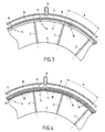
- Figures 4 and 5 show an alternative embodiment of the invention.
- the radially inner wall 18 of the toroidal collector 8 presents in steps angular Has a plurality of regularly distributed holes 19, in place of the annular slot 9 described above. These holes 19 have a diameter equal to at least at diameter of the orifice 11 having the largest diameter.
- the holes 11 of the ring 10 can be positioned in front of a clearance of holes 19 depending on the engine speed of the turbojet engine.
- the ring 9 is also rotated around the axis of rotation of the blower by a motor 15 controlled by a controller 16 which receives signals from an electronic engine speed control device.
Landscapes
- Engineering & Computer Science (AREA)
- Chemical & Material Sciences (AREA)
- Combustion & Propulsion (AREA)
- Mechanical Engineering (AREA)
- General Engineering & Computer Science (AREA)
- Structures Of Non-Positive Displacement Pumps (AREA)
- Control Of Turbines (AREA)
Abstract
Description
Claims (9)
- Procédé d'atténuation des sons produits dans une turbomachine par l'interaction des aubes mobiles (1) d'une couronne d'aubes rotoriques et des aubes fixes (2) d'une couronne d'aubes statoriques, disposée en aval de la couronne d'aubes rotoriques, procédé selon lequel on crée un contre-bruit en opposition de phase au moyen d'une injection de fluide dans le canal de l'écoulement (3) à travers des orifice(11) en nombre égal à celui des aubes fixes (2) de la couronne d'aubes statoriques, caractérisé par le fait que l'on injecte le fluide dans le canal d'écoulement (3) en amont de la couronne d'aubes rotoriques sous forme de jets continus (14) à travers les orifices (11) et par le fait que l'on règle la position angulaire des orifices (11) par rapport aux aubes fixes (2) de manière que les ondes acoustiques créées par l'interaction des jets (14) et des aubes mobiles (1) soient sensiblement en opposition de phase avec celles créées par l'interaction des aubes mobiles (1) et des aubes fixes.
- Procédé selon la revendication 1, caractérisé par le fait que l'on règle la position angulaire des orifices (11) par rapport aux aubes fixes (2) de manière continue.
- Procédé selon la revendication 1, caractérisé par le fait que l'on règle la position angulaire des orifices (11) par rapport aux aubes fixes (2) de manière discontinue en fonction du régime moteur.
- Procédé selon l'une quelconque des revendications 1 à 3, appliqué à l'atténuation des sons produits par une soufflante d'un turboréacteur double flux dont le canal d'écoulement (3) est traversé par des bras de support (7), caractérisé par le fait que l'on calcule la position et le diamètre des orifices (11) d'injection de manière à prendre en compte la distorsion de vitesse créée par les bras de support (7).
- Dispositif pour la mise en oeuvre du procédé selon l'une des revendications précédentes, caractérisé par le fait que les orifices (11) d'injection sont ménagés dans un anneau (10) porté par le carter, ledit anneau (10) étant de révolution autour de l'axe de rotation du rotor et étant susceptible de pivoter d'un angle (A) au moins égal au pas angulaire des aubes fixes (2).
- Dispositif selon la revendication 5, caractérisé par le fait qu'il comporte en outre un moteur d'entraínement (15) de l'anneau (10) commandé par un contrôleur (16).
- Dispositif selon la revendication 6, caractérisé par le fait que l'anneau (10) est disposé dans un collecteur annulaire (8) qui présente une fente annulaire (9) en regard des orifices (11)
- Dispositif selon la revendication 5, caractérisé par le fait que l'anneau (10) est disposé dans un collecteur (8) qui présente en regard du chemin des orifices (11) et par pas angulaire A des aubes fixes (2) une pluralité de trous (19) répartis ayant un diamètre au moins égal au diamètre de l'orifice (11) correspondant.
- Dispositif selon la revendication 8, caractérisé par le fait qu'il comporte en outre des moyens (15) pour positionner les orifices (11) devant un jeu de trous (19) en fonction du régime moteur.
Applications Claiming Priority (2)
| Application Number | Priority Date | Filing Date | Title |
|---|---|---|---|
| FR0012016 | 2000-09-21 | ||
| FR0012016A FR2814197B1 (fr) | 2000-09-21 | 2000-09-21 | Procede et dispositif pour l'attenuation des sons d'interaction rotor/stator dans une turbomachine |
Publications (2)
| Publication Number | Publication Date |
|---|---|
| EP1191205A1 true EP1191205A1 (fr) | 2002-03-27 |
| EP1191205B1 EP1191205B1 (fr) | 2006-07-12 |
Family
ID=8854516
Family Applications (1)
| Application Number | Title | Priority Date | Filing Date |
|---|---|---|---|
| EP01402409A Expired - Lifetime EP1191205B1 (fr) | 2000-09-21 | 2001-09-20 | Procédé pour l'atténuation des sons d'interaction rotor/stator, dans une turbomachine et dispositif pour la mise en oeuvre de ce procédé |
Country Status (10)
| Country | Link |
|---|---|
| US (1) | US6546734B2 (fr) |
| EP (1) | EP1191205B1 (fr) |
| JP (1) | JP4127991B2 (fr) |
| CA (1) | CA2357305C (fr) |
| DE (1) | DE60121400T2 (fr) |
| ES (1) | ES2262617T3 (fr) |
| FR (1) | FR2814197B1 (fr) |
| RU (1) | RU2246632C2 (fr) |
| UA (1) | UA74387C2 (fr) |
| WO (1) | WO2002025084A1 (fr) |
Cited By (3)
| Publication number | Priority date | Publication date | Assignee | Title |
|---|---|---|---|---|
| EP2009263A3 (fr) * | 2007-06-26 | 2012-07-04 | United Technologies Corporation | Alimentation en air tangentielle anti-tourbillonnement |
| EP1942259A3 (fr) * | 2006-12-28 | 2014-04-30 | General Electric Company | Contrôle de la ligne de fonctionnement d'un système de compression avec recirculation du flux |
| FR3080649A1 (fr) * | 2018-04-27 | 2019-11-01 | Safran Aircraft Engines | Veine de decharge integree a une aube |
Families Citing this family (27)
| Publication number | Priority date | Publication date | Assignee | Title |
|---|---|---|---|---|
| EP1623104A1 (fr) * | 2003-05-15 | 2006-02-08 | Alstom Technology Ltd | Dispositif d'isolation phonique dans un canal d'ecoulement |
| US7631483B2 (en) | 2003-09-22 | 2009-12-15 | General Electric Company | Method and system for reduction of jet engine noise |
| US7497300B2 (en) * | 2004-03-18 | 2009-03-03 | D Angelo John P | Noise reduction tubes |
| US8033358B2 (en) * | 2007-04-26 | 2011-10-11 | Lord Corporation | Noise controlled turbine engine with aircraft engine adaptive noise control tubes |
| FR2926536B1 (fr) * | 2008-01-23 | 2010-07-30 | Snecma | Accrochage d'un systeme propulsif a un element de structure d'un aeronef |
| US8640820B2 (en) * | 2012-01-11 | 2014-02-04 | Polytechnic Institute Of New York University | High-speed jet noise reduction via fluidic injection |
| RU2580980C2 (ru) * | 2014-07-24 | 2016-04-10 | Российская Федерация в лице Министерства промышленности и торговли Российской Федерации (Минпромторг России) | Способ расстановки лопаток в рабочем колесе вентилятора авиационного двигателя |
| US20180363676A1 (en) * | 2017-06-16 | 2018-12-20 | General Electric Company | Inlet pre-swirl gas turbine engine |
| US10815886B2 (en) | 2017-06-16 | 2020-10-27 | General Electric Company | High tip speed gas turbine engine |
| US10724435B2 (en) | 2017-06-16 | 2020-07-28 | General Electric Co. | Inlet pre-swirl gas turbine engine |
| US10711797B2 (en) | 2017-06-16 | 2020-07-14 | General Electric Company | Inlet pre-swirl gas turbine engine |
| US10794396B2 (en) | 2017-06-16 | 2020-10-06 | General Electric Company | Inlet pre-swirl gas turbine engine |
| US11333079B2 (en) * | 2020-04-28 | 2022-05-17 | General Electric Company | Methods and apparatus to detect air flow separation of an engine |
| US11828237B2 (en) | 2020-04-28 | 2023-11-28 | General Electric Company | Methods and apparatus to control air flow separation of an engine |
| US11428160B2 (en) | 2020-12-31 | 2022-08-30 | General Electric Company | Gas turbine engine with interdigitated turbine and gear assembly |
| CN113803983B (zh) * | 2021-10-12 | 2022-06-10 | 浙江至煜纺织科技有限公司 | 一种节能型涤纶原料干燥装置及方法 |
| US11702945B2 (en) * | 2021-12-22 | 2023-07-18 | Rolls-Royce North American Technologies Inc. | Turbine engine fan case with tip injection air recirculation passage |
| US20230265862A1 (en) | 2022-02-21 | 2023-08-24 | General Electric Company | Turbofan engine having angled inlet pre-swirl vanes |
| US11725526B1 (en) | 2022-03-08 | 2023-08-15 | General Electric Company | Turbofan engine having nacelle with non-annular inlet |
| US20230323834A1 (en) * | 2022-04-08 | 2023-10-12 | General Electric Company | Gas turbine engine with a compressed airflow injection assembly |
| US12275532B2 (en) | 2022-08-15 | 2025-04-15 | General Electric Company | Gas turbine engine noise reduction |
| US12352181B2 (en) | 2023-01-30 | 2025-07-08 | General Electric Company | Turbine airfoils |
| US12209557B1 (en) | 2023-11-30 | 2025-01-28 | General Electric Company | Gas turbine engine with forward swept outlet guide vanes |
| US12385430B2 (en) | 2023-11-30 | 2025-08-12 | General Electric Company | Gas turbine engine with forward swept outlet guide vanes |
| US12228037B1 (en) | 2023-12-04 | 2025-02-18 | General Electric Company | Guide vane assembly with fixed and variable pitch inlet guide vanes |
| US12146413B1 (en) * | 2023-12-12 | 2024-11-19 | Rolls-Royce North American Technologies Inc. | Circumferentially variable flow control in fan outlet guide vane assemblies for distortion management and stall margin in gas turbine engines |
| US12313021B1 (en) | 2024-03-14 | 2025-05-27 | General Electric Company | Outer nacelle with inlet guide vanes and acoustic treatment |
Citations (3)
| Publication number | Priority date | Publication date | Assignee | Title |
|---|---|---|---|---|
| FR2370170A1 (fr) | 1976-11-05 | 1978-06-02 | Snecma | Procede et dispositif pour la diminution du bruit des turbomachines |
| US4199295A (en) * | 1976-11-05 | 1980-04-22 | Societe Nationale D'etude Et De Construction De Moteurs D'aviation | Method and device for reducing the noise of turbo-machines |
| EP0899427A2 (fr) * | 1997-08-29 | 1999-03-03 | United Technologies Corporation | Amortissement actif des vibrations dans un étage d'un rotor d'une turbomachine |
Family Cites Families (6)
| Publication number | Priority date | Publication date | Assignee | Title |
|---|---|---|---|---|
| US3363419A (en) * | 1965-04-27 | 1968-01-16 | Rolls Royce | Gas turbine ducted fan engine |
| US3508838A (en) * | 1968-09-16 | 1970-04-28 | Gen Electric | Sound suppression of compressors used in gas turbine engines |
| US3572960A (en) * | 1969-01-02 | 1971-03-30 | Gen Electric | Reduction of sound in gas turbine engines |
| US4044203A (en) * | 1972-11-24 | 1977-08-23 | National Research Development Corporation | Active control of sound waves |
| JP3434830B2 (ja) * | 1994-10-13 | 2003-08-11 | ザ・ボーイング・カンパニー | ジェットエンジンのための騒音低減システムおよび騒音制御方法 |
| US6409469B1 (en) * | 2000-11-21 | 2002-06-25 | Pratt & Whitney Canada Corp. | Fan-stator interaction tone reduction |
-
2000
- 2000-09-21 FR FR0012016A patent/FR2814197B1/fr not_active Expired - Fee Related
-
2001
- 2001-09-13 CA CA002357305A patent/CA2357305C/fr not_active Expired - Fee Related
- 2001-09-20 UA UA2003032425A patent/UA74387C2/uk unknown
- 2001-09-20 RU RU2003111156/06A patent/RU2246632C2/ru not_active IP Right Cessation
- 2001-09-20 WO PCT/FR2001/002916 patent/WO2002025084A1/fr not_active Ceased
- 2001-09-20 EP EP01402409A patent/EP1191205B1/fr not_active Expired - Lifetime
- 2001-09-20 JP JP2001286291A patent/JP4127991B2/ja not_active Expired - Fee Related
- 2001-09-20 ES ES01402409T patent/ES2262617T3/es not_active Expired - Lifetime
- 2001-09-20 DE DE60121400T patent/DE60121400T2/de not_active Expired - Lifetime
- 2001-09-21 US US09/956,830 patent/US6546734B2/en not_active Expired - Lifetime
Patent Citations (4)
| Publication number | Priority date | Publication date | Assignee | Title |
|---|---|---|---|---|
| FR2370170A1 (fr) | 1976-11-05 | 1978-06-02 | Snecma | Procede et dispositif pour la diminution du bruit des turbomachines |
| US4199295A (en) * | 1976-11-05 | 1980-04-22 | Societe Nationale D'etude Et De Construction De Moteurs D'aviation | Method and device for reducing the noise of turbo-machines |
| US4255083A (en) * | 1976-11-05 | 1981-03-10 | Societe Nationale D'etude Et De Construction De Moteurs D'aviation | Method and device for reducing the noise of turbo-machines |
| EP0899427A2 (fr) * | 1997-08-29 | 1999-03-03 | United Technologies Corporation | Amortissement actif des vibrations dans un étage d'un rotor d'une turbomachine |
Cited By (3)
| Publication number | Priority date | Publication date | Assignee | Title |
|---|---|---|---|---|
| EP1942259A3 (fr) * | 2006-12-28 | 2014-04-30 | General Electric Company | Contrôle de la ligne de fonctionnement d'un système de compression avec recirculation du flux |
| EP2009263A3 (fr) * | 2007-06-26 | 2012-07-04 | United Technologies Corporation | Alimentation en air tangentielle anti-tourbillonnement |
| FR3080649A1 (fr) * | 2018-04-27 | 2019-11-01 | Safran Aircraft Engines | Veine de decharge integree a une aube |
Also Published As
| Publication number | Publication date |
|---|---|
| DE60121400T2 (de) | 2007-07-05 |
| UA74387C2 (uk) | 2005-12-15 |
| CA2357305C (fr) | 2007-08-14 |
| EP1191205B1 (fr) | 2006-07-12 |
| US20020048511A1 (en) | 2002-04-25 |
| FR2814197A1 (fr) | 2002-03-22 |
| RU2246632C2 (ru) | 2005-02-20 |
| JP2002155897A (ja) | 2002-05-31 |
| FR2814197B1 (fr) | 2003-01-10 |
| CA2357305A1 (fr) | 2002-03-21 |
| ES2262617T3 (es) | 2006-12-01 |
| JP4127991B2 (ja) | 2008-07-30 |
| DE60121400D1 (de) | 2006-08-24 |
| WO2002025084A1 (fr) | 2002-03-28 |
| US6546734B2 (en) | 2003-04-15 |
Similar Documents
| Publication | Publication Date | Title |
|---|---|---|
| EP1191205B1 (fr) | Procédé pour l'atténuation des sons d'interaction rotor/stator, dans une turbomachine et dispositif pour la mise en oeuvre de ce procédé | |
| KR100539037B1 (ko) | 작동로터스테이지진동제어장치 | |
| EP1566522B1 (fr) | Turboréacteur à double soufflante ayant des aubes directrices à calage variable | |
| CA2500491C (fr) | Dispositif de pilotage de jeu de turbine a gaz a equilibrage des debits d'air | |
| FR2931906A1 (fr) | Compresseur de turbomachine avec un systeme d'injection d'air. | |
| RU2003111156A (ru) | Способ подавления акустических шумов, возникающих в результате взаимодействия между ротором и статором в газотурбинном двигателе, и устройство для осуществления этого способа | |
| FR3090049A1 (fr) | Turbomachine comportant un alternateur entre deux elements contrarotatifs | |
| JP2011508237A (ja) | タービンロータ組立体をバランスさせるための方法及びシステム | |
| FR2641573A1 (fr) | Rotor de turbomachine muni d'un dispositif de fixation des aubes | |
| CA2801193A1 (fr) | Procede et systeme de pilotage de jeu en sommet d'aubes de rotor de turbine | |
| EP0589745B1 (fr) | Système de réglage d'alimentation d'une turbomachine | |
| FR2844877A1 (fr) | Procede pour l'equilibrage rotatif d'un rotor de turbocompresseur avec machine electrique rotative | |
| EP3314131A1 (fr) | Système de commande d'aubes à calage variable pour une turbomachine | |
| EP3762595B1 (fr) | Dispositif actif d'atténuation des émissions acoustiques pour un turboréacteur comportant des turbines contrôlées | |
| EP3580432B1 (fr) | Turboréacteur à architecture de paliers optimisée pour le support d'un arbre basse pression | |
| EP3438000B1 (fr) | Système actif générant des interférences acoustiques destructives pour moteur d'aéronef à plusieurs corps de soufflante | |
| CA2874841C (fr) | Soufflante a calage variable par rotation differentielle des disques de soufflante | |
| FR2766988A1 (fr) | Dispositif et procede d'equilibrage d'un rotor de machine tournante rapide | |
| EP4179190B1 (fr) | Méthode et système de régulation de poussée d'une turbomachine d'aéronef | |
| FR2599436A1 (fr) | Diffuseur. | |
| FR3129175B1 (fr) | Module de turbomachine avec un dispositif de limitation d’amplitude et turbomachine correpondante | |
| FR2867805A1 (fr) | Stator de turbine haute-pression de turbomachine et procede d'assemblage | |
| EP4004346A1 (fr) | Turbomachine axiale et étage redresseur à aubes à orientation variable pour turbomachine axiale | |
| FR2887939A1 (fr) | Compresseur multi-etages de turbomachine | |
| FR2947312A1 (fr) | Procede et appareil de controle du bruit sonore des ventilateurs subsoniques |
Legal Events
| Date | Code | Title | Description |
|---|---|---|---|
| PUAI | Public reference made under article 153(3) epc to a published international application that has entered the european phase |
Free format text: ORIGINAL CODE: 0009012 |
|
| 17P | Request for examination filed |
Effective date: 20011004 |
|
| AK | Designated contracting states |
Kind code of ref document: A1 Designated state(s): AT BE CH CY DE DK ES FI FR GB GR IE IT LI LU MC NL PT SE TR Kind code of ref document: A1 Designated state(s): DE ES FR GB IT SE |
|
| AX | Request for extension of the european patent |
Free format text: AL;LT;LV;MK;RO;SI |
|
| AKX | Designation fees paid |
Free format text: DE ES FR GB IT SE |
|
| RAP1 | Party data changed (applicant data changed or rights of an application transferred) |
Owner name: SNECMA |
|
| GRAP | Despatch of communication of intention to grant a patent |
Free format text: ORIGINAL CODE: EPIDOSNIGR1 |
|
| GRAS | Grant fee paid |
Free format text: ORIGINAL CODE: EPIDOSNIGR3 |
|
| GRAA | (expected) grant |
Free format text: ORIGINAL CODE: 0009210 |
|
| AK | Designated contracting states |
Kind code of ref document: B1 Designated state(s): DE ES FR GB IT SE |
|
| REG | Reference to a national code |
Ref country code: GB Ref legal event code: FG4D Free format text: NOT ENGLISH |
|
| REF | Corresponds to: |
Ref document number: 60121400 Country of ref document: DE Date of ref document: 20060824 Kind code of ref document: P |
|
| GBT | Gb: translation of ep patent filed (gb section 77(6)(a)/1977) |
Effective date: 20060809 |
|
| REG | Reference to a national code |
Ref country code: SE Ref legal event code: TRGR |
|
| REG | Reference to a national code |
Ref country code: ES Ref legal event code: FG2A Ref document number: 2262617 Country of ref document: ES Kind code of ref document: T3 |
|
| PLBE | No opposition filed within time limit |
Free format text: ORIGINAL CODE: 0009261 |
|
| STAA | Information on the status of an ep patent application or granted ep patent |
Free format text: STATUS: NO OPPOSITION FILED WITHIN TIME LIMIT |
|
| 26N | No opposition filed |
Effective date: 20070413 |
|
| PGFP | Annual fee paid to national office [announced via postgrant information from national office to epo] |
Ref country code: ES Payment date: 20120910 Year of fee payment: 12 |
|
| PGFP | Annual fee paid to national office [announced via postgrant information from national office to epo] |
Ref country code: DE Payment date: 20130820 Year of fee payment: 13 Ref country code: SE Payment date: 20130823 Year of fee payment: 13 |
|
| PGFP | Annual fee paid to national office [announced via postgrant information from national office to epo] |
Ref country code: IT Payment date: 20130826 Year of fee payment: 13 |
|
| REG | Reference to a national code |
Ref country code: ES Ref legal event code: FD2A Effective date: 20141007 |
|
| PG25 | Lapsed in a contracting state [announced via postgrant information from national office to epo] |
Ref country code: ES Free format text: LAPSE BECAUSE OF NON-PAYMENT OF DUE FEES Effective date: 20130921 |
|
| REG | Reference to a national code |
Ref country code: DE Ref legal event code: R119 Ref document number: 60121400 Country of ref document: DE |
|
| REG | Reference to a national code |
Ref country code: SE Ref legal event code: EUG |
|
| PG25 | Lapsed in a contracting state [announced via postgrant information from national office to epo] |
Ref country code: SE Free format text: LAPSE BECAUSE OF NON-PAYMENT OF DUE FEES Effective date: 20140921 |
|
| PG25 | Lapsed in a contracting state [announced via postgrant information from national office to epo] |
Ref country code: DE Free format text: LAPSE BECAUSE OF NON-PAYMENT OF DUE FEES Effective date: 20150401 |
|
| PG25 | Lapsed in a contracting state [announced via postgrant information from national office to epo] |
Ref country code: IT Free format text: LAPSE BECAUSE OF NON-PAYMENT OF DUE FEES Effective date: 20140920 |
|
| REG | Reference to a national code |
Ref country code: FR Ref legal event code: PLFP Year of fee payment: 16 |
|
| REG | Reference to a national code |
Ref country code: FR Ref legal event code: PLFP Year of fee payment: 17 |
|
| REG | Reference to a national code |
Ref country code: FR Ref legal event code: CD Owner name: SAFRAN AIRCRAFT ENGINES Effective date: 20170719 |
|
| REG | Reference to a national code |
Ref country code: FR Ref legal event code: PLFP Year of fee payment: 18 |
|
| PGFP | Annual fee paid to national office [announced via postgrant information from national office to epo] |
Ref country code: GB Payment date: 20200819 Year of fee payment: 20 Ref country code: FR Payment date: 20200819 Year of fee payment: 20 |
|
| REG | Reference to a national code |
Ref country code: GB Ref legal event code: PE20 Expiry date: 20210919 |
|
| PG25 | Lapsed in a contracting state [announced via postgrant information from national office to epo] |
Ref country code: GB Free format text: LAPSE BECAUSE OF EXPIRATION OF PROTECTION Effective date: 20210919 |