EP1190980A2 - Method for controlling crane brake operation - Google Patents
Method for controlling crane brake operation Download PDFInfo
- Publication number
- EP1190980A2 EP1190980A2 EP01660170A EP01660170A EP1190980A2 EP 1190980 A2 EP1190980 A2 EP 1190980A2 EP 01660170 A EP01660170 A EP 01660170A EP 01660170 A EP01660170 A EP 01660170A EP 1190980 A2 EP1190980 A2 EP 1190980A2
- Authority
- EP
- European Patent Office
- Prior art keywords
- load
- brake
- information
- crane
- motor
- Prior art date
- Legal status (The legal status is an assumption and is not a legal conclusion. Google has not performed a legal analysis and makes no representation as to the accuracy of the status listed.)
- Granted
Links
Images
Classifications
-
- B—PERFORMING OPERATIONS; TRANSPORTING
- B66—HOISTING; LIFTING; HAULING
- B66D—CAPSTANS; WINCHES; TACKLES, e.g. PULLEY BLOCKS; HOISTS
- B66D5/00—Braking or detent devices characterised by application to lifting or hoisting gear, e.g. for controlling the lowering of loads
- B66D5/02—Crane, lift hoist, or winch brakes operating on drums, barrels, or ropes
- B66D5/24—Operating devices
- B66D5/30—Operating devices electrical
-
- B—PERFORMING OPERATIONS; TRANSPORTING
- B66—HOISTING; LIFTING; HAULING
- B66C—CRANES; LOAD-ENGAGING ELEMENTS OR DEVICES FOR CRANES, CAPSTANS, WINCHES, OR TACKLES
- B66C13/00—Other constructional features or details
- B66C13/18—Control systems or devices
- B66C13/22—Control systems or devices for electric drives
- B66C13/23—Circuits for controlling the lowering of the load
Definitions
- the invention relates to a method for controlling the operation of a crane brake, the crane comprising an electric motor controlled by means of a frequency converter for hoisting and lowering movements of the crane; an electromechanical brake having an impact on said movements, the brake being opened when the motor is started for a hoisting or lowering operation; a load sensor weighing the load to be handled; and an overload protection connected to the sensor.
- Electromechanical brakes are currently delivered either with no controls or provided with a micro switch arranged to measure the movement of the brake anchor plate. When the brake is in operation this movement is extremely small, typically 0.2-0.4 mm. The operating range of the switch is therefore very small and its mounting and tuning is difficult.
- a control or monitoring system is provided with a measuring circuit to ensure that when a load hoisting or lowering movement begins, the brake opens, i.e. the micro switch is closed. If the switch does not close within a predetermined time, the operation of the crane is stopped.
- JP 2-084088 and FR 2 675 790 disclose brake control methods based on the above micro switch solutions to indicate brake position. Such unreliable solutions have been used in shoe brakes already for decades.
- Publication JP 4-265681 teaches a method for detecting a brake malfunction, in which method motor current is gradually increased and measured with a speed sensor to indicate when the motor starts to rotate. The differences in currents between brakes with and without voltage are then compared. If the difference between the currents is too small, the brake is detected to be faulty.
- US Patent 4,733,148 discloses a method in which the motor is driven at a nominal torque, and a speed feedback sensor reading will show whether the motor is running. This method cannot be applied as such to cranes. If the hoisting member is provided with a nominal load and the load is being brought downward at a nominal torque against the brake, the brake is in fact required to slip. US Patent 5,343,134 teaches a similar system in which the brake is monitored by checking the rotating speed of the motor. Although the system works for cranes, it also requires the speed of rotation of the motor to be known.
- the invention is based on simply comparing the load weighing information with the motor torque information whenever the crane is operated. If the torque does not correspond to the information provided by the load sensor, there are additional losses in the system, either in the brake or some other mechanical structure. The crane can thus be halted before the brake warms up excessively.
- the comparison according to the invention must be made taking the drive or hoisting direction into account: when the load is taken upward, the torque is scaled such that a nominal torque (100% torque) is required to hoist a nominal load (100%), whereby mutually corresponding load information and torque information are obtained within the entire load range.
- the motor When the load is being lowered, the motor functions as a generator, the torque with nominal load (100%) being (machinery efficiency) 2 x 100% torque (of a minus sign), which is -80 ... -90%, depending on the efficiency.
- the torque needed by the motor increases when the load is being hoisted and, correspondingly, the torque on the generator side decreases when the load is being lowered.
- the control unit is provided with settable limits in which the torque information must be proportional to the load information, and with necessary filtering elements for filtering the torque needed for accelerating flier masses, although the torque can also be removed computationally on the basis of known acceleration and deceleration times and flier masses of the machinery.
- the control can be implemented for example as follows:
- This control can be programmed into the frequency converter or another programmable device.
- the most advantageous solution is naturally to program the function into the frequency converter itself because then the control can be implemented without any additional equipment.
- a significant advantage of the invention is that systems already existing in the crane can be used for making reliable conclusions about the performance of the brake and another mechanical system, whereby additional sensors, which are expensive and difficult to provide, can be avoided.
- additional sensors which are expensive and difficult to provide
- increased crane reliability is obtained compared with solutions based on micro switches because the system also detects other than brake faults in the hoisting apparatus (such as bearing damages, rope jamming, etc.)
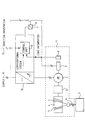
- a crane hoisting apparatus denoted with reference numeral 1 comprises an electric motor 2 serving as an operating power source, the motor operating a lifting drum 4 through gearing 3, the drum being provided with lifting ropes 5 spooled on the drum, and the ends of the ropes being in turn provided with a lifting hook 6 for seizing a load 7.
- the hoisting apparatus 1 further comprises a load sensor 8 measuring the weight of the load 7 and an electromechanical brake 9 for braking the motor 2 and, thereby, the lifting drum 4.
- the motor 2, and thereby the hoisting and lowering movements of the crane, are controlled by means of a frequency converter 10 to which the crane operator issues commands on a direction information line 13.
- control unit 12 For controlling the braking operation, there is provided a control unit 12 which is placed in this case into the frequency converter 10 itself.
- the control unit 12 receives hoisting direction information over the line 13.
- Reference numeral 11 denotes a supply voltage line of the hoisting machinery.
- a brake controller 14 which either keeps the brake 9 entirely open or closed, depending on the information received from the control unit 12.
- the frequency converter 10 calculates the torque of the motor 2 and transmits the information to the control unit 12.
- the unit 12 continuously compares this computational torque information with the weighing information produced by the load sensor 8. If the load information and the torque information do not correspond to each other within the set tolerances (with the above described hoisting direction taken into account), the brake 9 is applied to stop the motor 2 which remains stopped for as long as there is the difference between said information, i.e. a disturbance or malfunction in the brakes.
Landscapes
- Engineering & Computer Science (AREA)
- Mechanical Engineering (AREA)
- Automation & Control Theory (AREA)
- Control And Safety Of Cranes (AREA)
Abstract
Description
Claims (3)
- A method for controlling the operation of a crane brake, the crane comprising an electric motor (2) controlled by means of a frequency converter (10) for hoisting and lowering movements of the crane; an electromechanical brake (9) having an impact on said movements, the brake being opened when the motor is started for a hoisting or lowering operation; a load sensor (8) weighing a load (7) to be handled; and an overload protection connected to the sensor, characterized in that the frequency converter (10) is used for calculating the torque of the motor (2), which information is compared with the load information, or weight, obtained from the load sensor (8).
- A method according to claim 1, characterized in that when the load (7) is being hoisted, the hoisting movement is stopped if the load information and the torque information do not substantially correspond to each other, and when the load is being lowered, the lowering movement is stopped, if the torque information is substantially different from a minus-sign product (machinery efficiency)2 x load information.
- A method according to claim 1 or 2, characterized in that the control operations are programmed into the frequency converter (10).
Applications Claiming Priority (2)
| Application Number | Priority Date | Filing Date | Title |
|---|---|---|---|
| FI20002084A FI108718B (en) | 2000-09-21 | 2000-09-21 | Method for monitoring the operation of a crane brake |
| FI20002084 | 2000-09-21 |
Publications (3)
| Publication Number | Publication Date |
|---|---|
| EP1190980A2 true EP1190980A2 (en) | 2002-03-27 |
| EP1190980A3 EP1190980A3 (en) | 2005-10-26 |
| EP1190980B1 EP1190980B1 (en) | 2007-11-07 |
Family
ID=8559132
Family Applications (1)
| Application Number | Title | Priority Date | Filing Date |
|---|---|---|---|
| EP01660170A Expired - Lifetime EP1190980B1 (en) | 2000-09-21 | 2001-09-14 | Method for controlling crane brake operation |
Country Status (5)
| Country | Link |
|---|---|
| US (1) | US6655662B2 (en) |
| EP (1) | EP1190980B1 (en) |
| DE (1) | DE60131231T2 (en) |
| ES (1) | ES2292552T3 (en) |
| FI (1) | FI108718B (en) |
Cited By (3)
| Publication number | Priority date | Publication date | Assignee | Title |
|---|---|---|---|---|
| CN101134554B (en) * | 2006-08-31 | 2011-12-14 | 罗兹勒有限责任两合公司 | Winch |
| CN108957318A (en) * | 2018-07-17 | 2018-12-07 | 简佑科技河北有限公司 | Door roller Performance Test System and method |
| WO2019232937A1 (en) * | 2018-06-08 | 2019-12-12 | 江苏金恒信息科技股份有限公司 | Four-rope grab bucket slag material grabbing system and method |
Families Citing this family (25)
| Publication number | Priority date | Publication date | Assignee | Title |
|---|---|---|---|---|
| US20050017228A1 (en) * | 2003-07-22 | 2005-01-27 | Werner Peter Harold | Winch control method and apparatus |
| JP2005054843A (en) * | 2003-08-01 | 2005-03-03 | Fanuc Ltd | Brake device |
| US7190146B1 (en) | 2003-08-18 | 2007-03-13 | Magnetek, Inc. | Control system and method for an overhead bridge crane |
| US7293761B2 (en) * | 2003-10-16 | 2007-11-13 | American Crane & Equipment Corporation | Diagnostic system for cranes |
| CN100357171C (en) * | 2005-02-01 | 2007-12-26 | 太原重型机械集团有限公司 | Lifting mechanism braking system of hoister |
| DE102006003832B4 (en) * | 2006-01-26 | 2008-10-16 | Bubenzer Bremsen Gerhard Bubenzer Ing. Gmbh | Control and regulating arrangement for securing a conveyor, conveyor and crane system |
| CN100465846C (en) * | 2006-09-15 | 2009-03-04 | 上海三一科技有限公司 | Crawler crane torque controlling method and apparatus under super lifting working condition |
| EP2225569B1 (en) * | 2007-11-26 | 2013-08-14 | SafeWorks, LLC | Power sensor |
| FR2949627B1 (en) * | 2009-09-03 | 2011-10-07 | Manitowoc Crane Group France | METHOD FOR VERIFYING THE STATUS OF A BRAKE OF A MECHANISM CONTROLLED BY A FREQUENCY CONVERTER OR OTHER CONTROLLER |
| US9120645B2 (en) * | 2011-11-16 | 2015-09-01 | Spacelift Products, Inc. | Control system for a platform lift apparatus |
| CN103166195B (en) * | 2011-12-19 | 2016-07-06 | 苏州汇川技术有限公司 | converter stall protection system and method |
| DE202013100340U1 (en) * | 2012-07-13 | 2013-02-08 | Rofa Industrial Automation Ag | Hubtischsteuerung |
| DE102013200514A1 (en) * | 2013-01-15 | 2014-07-17 | Sibre Siegerland-Bremsen Gmbh | Overload protection for conveyors, in particular cranes |
| CN103193176A (en) * | 2013-04-25 | 2013-07-10 | 山东建设机械股份有限公司 | Hoisting system with overweight pre-warning function |
| EP2999658B1 (en) * | 2013-05-22 | 2018-07-04 | KONE Corporation | Method and test system for testing failure of a machinery brake of an elevator |
| JP6325801B2 (en) * | 2013-11-20 | 2018-05-16 | 株式会社神戸製鋼所 | Electric winch device |
| DE102015218300C5 (en) * | 2015-09-23 | 2025-01-02 | Flender Gmbh | Motor-driven crane drive and method for its operation |
| US9950908B2 (en) | 2016-03-10 | 2018-04-24 | Magnetek, Inc. | System and method for determining a load in a material handling system |
| DE102016109295A1 (en) | 2016-05-20 | 2017-11-23 | Terex Mhps Gmbh | Hoist and method for operating a hoist |
| CN106115528B (en) * | 2016-06-28 | 2019-05-17 | 重庆川九建设有限责任公司 | Wire rope overload protection system for sinking winch |
| DE102017001238A1 (en) * | 2017-02-09 | 2018-08-09 | Liebherr-Components Biberach Gmbh | Hoist and method for starting the hoist of such a hoist |
| DE102018105139A1 (en) * | 2018-03-06 | 2019-09-12 | Konecranes Global Corporation | Method for controlling and in particular monitoring an actuator, in particular a winch, a hoist or a crane, and system for carrying out such a method |
| CN109179216A (en) * | 2018-10-18 | 2019-01-11 | 上海川丰机电科技发展有限公司 | Gantry crane cart wind prevention braking method and its system |
| CN113620176B (en) * | 2020-05-09 | 2024-08-02 | 安川电机(中国)有限公司 | Control method and device for hoisting equipment |
| CN116425042A (en) * | 2023-03-28 | 2023-07-14 | 华能澜沧江水电股份有限公司 | Frequency conversion control method and device for hoisting equipment |
Family Cites Families (14)
| Publication number | Priority date | Publication date | Assignee | Title |
|---|---|---|---|---|
| US3693939A (en) * | 1971-04-22 | 1972-09-26 | All American Ind | Tension control system |
| JPS60244779A (en) * | 1984-05-17 | 1985-12-04 | 三菱電機株式会社 | Controller for speed of elevator |
| DE3447090A1 (en) * | 1984-12-22 | 1986-06-26 | Heidelberger Druckmaschinen Ag, 6900 Heidelberg | METHOD AND DEVICE FOR BRAKE CONTROL OF A MOTION MONITORED AND CONTROLLED DRIVE MOTOR IN A PRINTING MACHINE |
| JPH01214596A (en) * | 1988-02-23 | 1989-08-28 | Toshiba Corp | Controller for shaft winding-up machine |
| JP3001159B2 (en) * | 1988-09-19 | 2000-01-24 | 日立機電工業株式会社 | Crane brake operation control method |
| JP3081258B2 (en) * | 1991-02-19 | 2000-08-28 | 帝人製機株式会社 | Brake failure detection method |
| FR2675790A1 (en) * | 1991-04-26 | 1992-10-30 | Materiel Ind Equipement | Device for monitoring a winch brake |
| US5343134A (en) * | 1993-05-03 | 1994-08-30 | Harnischfeger Corporation | Method for checking brake torque |
| FI97797C (en) * | 1994-09-30 | 1997-02-25 | Kone Oy | Procedure for starting an elevator |
| DE4440420C3 (en) * | 1994-11-07 | 2003-07-24 | Demag Cranes & Components Gmbh | Method and device for monitoring and / or controlling the speed of an electric drive with frequency converter for hoists |
| DE29622878U1 (en) * | 1996-03-06 | 1997-07-31 | Stemmann-Technik GmbH, 48465 Schüttorf | Arrangement for torque or speed control of a three-phase asynchronous motor assigned to a line drum winding or unwinding an energy supply line |
| US6051942A (en) * | 1996-04-12 | 2000-04-18 | Emerson Electric Motor Co. | Method and apparatus for controlling a switched reluctance machine |
| DE19645812C1 (en) * | 1996-11-07 | 1998-02-26 | Stahl R Foerdertech Gmbh | Electric hoist with microprocessor control system |
| US6029951A (en) * | 1998-07-24 | 2000-02-29 | Varco International, Inc. | Control system for drawworks operations |
-
2000
- 2000-09-21 FI FI20002084A patent/FI108718B/en not_active IP Right Cessation
-
2001
- 2001-09-14 ES ES01660170T patent/ES2292552T3/en not_active Expired - Lifetime
- 2001-09-14 EP EP01660170A patent/EP1190980B1/en not_active Expired - Lifetime
- 2001-09-14 DE DE60131231T patent/DE60131231T2/en not_active Expired - Lifetime
- 2001-09-18 US US09/954,079 patent/US6655662B2/en not_active Expired - Lifetime
Cited By (4)
| Publication number | Priority date | Publication date | Assignee | Title |
|---|---|---|---|---|
| CN101134554B (en) * | 2006-08-31 | 2011-12-14 | 罗兹勒有限责任两合公司 | Winch |
| WO2019232937A1 (en) * | 2018-06-08 | 2019-12-12 | 江苏金恒信息科技股份有限公司 | Four-rope grab bucket slag material grabbing system and method |
| CN108957318A (en) * | 2018-07-17 | 2018-12-07 | 简佑科技河北有限公司 | Door roller Performance Test System and method |
| CN108957318B (en) * | 2018-07-17 | 2020-10-30 | 简佑科技河北有限公司 | Rolling door machine performance test system and method |
Also Published As
| Publication number | Publication date |
|---|---|
| US20020033481A1 (en) | 2002-03-21 |
| DE60131231T2 (en) | 2008-05-15 |
| FI108718B (en) | 2002-03-15 |
| EP1190980B1 (en) | 2007-11-07 |
| ES2292552T3 (en) | 2008-03-16 |
| EP1190980A3 (en) | 2005-10-26 |
| FI20002084A0 (en) | 2000-09-21 |
| DE60131231D1 (en) | 2007-12-20 |
| US6655662B2 (en) | 2003-12-02 |
Similar Documents
| Publication | Publication Date | Title |
|---|---|---|
| US6655662B2 (en) | Method for controlling crane brake operation | |
| CN101268003B (en) | Elevator device | |
| US5343134A (en) | Method for checking brake torque | |
| KR100973880B1 (en) | Elevator device | |
| CN102036898B (en) | Elevator apparatus and operating method thereof | |
| US10196247B2 (en) | Electric winch device | |
| US5077508A (en) | Method and apparatus for determining load holding torque | |
| JPH08208189A (en) | Method and equipment for supervision of electric driving device and/or control of revolving speed | |
| US7686139B2 (en) | Elevator device | |
| JP6842403B2 (en) | Electric hoist and its operation control method | |
| CN110546102B (en) | Crane and overload detection method for crane | |
| CN112678637B (en) | Method for monitoring braking drag of elevator | |
| JPH11180687A (en) | Control method of hoist crane device | |
| CN101522553B (en) | Elevator apparatus | |
| JP2005170551A (en) | Elevator brake control device | |
| JP6996523B2 (en) | crane | |
| CN101798035B (en) | Lift device | |
| JP2012066893A (en) | Electrically driven hoisting machine with dynamic lift off stopping mechanism | |
| KR100295879B1 (en) | Method for controlling brake of elevator and detection apparatus thereof | |
| JP2011010440A (en) | Inverter device and teaching method for the same | |
| CN118083780A (en) | Intelligent grab crane anti-rope disorder control method and system | |
| CN115028072A (en) | Control method for controlling the handling of a suspended load in case of an emergency stop | |
| CN119095783A (en) | Inspection device and inspection method for elevator speed governor system | |
| HK40046326A (en) | A method for monitoring brake dragging of an elevator | |
| JP2000118963A (en) | Winch overhoisting preventive device |
Legal Events
| Date | Code | Title | Description |
|---|---|---|---|
| PUAI | Public reference made under article 153(3) epc to a published international application that has entered the european phase |
Free format text: ORIGINAL CODE: 0009012 |
|
| AK | Designated contracting states |
Kind code of ref document: A2 Designated state(s): AT BE CH CY DE DK ES FI FR GB GR IE IT LI LU MC NL PT SE TR |
|
| AX | Request for extension of the european patent |
Free format text: AL;LT;LV;MK;RO;SI |
|
| PUAL | Search report despatched |
Free format text: ORIGINAL CODE: 0009013 |
|
| AK | Designated contracting states |
Kind code of ref document: A3 Designated state(s): AT BE CH CY DE DK ES FI FR GB GR IE IT LI LU MC NL PT SE TR |
|
| AX | Request for extension of the european patent |
Extension state: AL LT LV MK RO SI |
|
| 17P | Request for examination filed |
Effective date: 20051124 |
|
| AKX | Designation fees paid |
Designated state(s): DE ES FR GB IT |
|
| GRAP | Despatch of communication of intention to grant a patent |
Free format text: ORIGINAL CODE: EPIDOSNIGR1 |
|
| GRAS | Grant fee paid |
Free format text: ORIGINAL CODE: EPIDOSNIGR3 |
|
| RAP1 | Party data changed (applicant data changed or rights of an application transferred) |
Owner name: KCI KONECRANES PLC |
|
| GRAA | (expected) grant |
Free format text: ORIGINAL CODE: 0009210 |
|
| AK | Designated contracting states |
Kind code of ref document: B1 Designated state(s): DE ES FR GB IT |
|
| REG | Reference to a national code |
Ref country code: GB Ref legal event code: FG4D |
|
| REF | Corresponds to: |
Ref document number: 60131231 Country of ref document: DE Date of ref document: 20071220 Kind code of ref document: P |
|
| REG | Reference to a national code |
Ref country code: ES Ref legal event code: FG2A Ref document number: 2292552 Country of ref document: ES Kind code of ref document: T3 |
|
| ET | Fr: translation filed | ||
| PLBE | No opposition filed within time limit |
Free format text: ORIGINAL CODE: 0009261 |
|
| STAA | Information on the status of an ep patent application or granted ep patent |
Free format text: STATUS: NO OPPOSITION FILED WITHIN TIME LIMIT |
|
| 26N | No opposition filed |
Effective date: 20080808 |
|
| REG | Reference to a national code |
Ref country code: FR Ref legal event code: PLFP Year of fee payment: 15 |
|
| REG | Reference to a national code |
Ref country code: DE Ref legal event code: R082 Ref document number: 60131231 Country of ref document: DE Representative=s name: K & H BONAPAT PATENTANWAELTE KOCH VON BEHREN &, DE Ref country code: DE Ref legal event code: R081 Ref document number: 60131231 Country of ref document: DE Owner name: KONECRANES GLOBAL CORP., FI Free format text: FORMER OWNER: KCI KONECRANES PLC, HYVINKAEAE, FI Ref country code: DE Ref legal event code: R082 Ref document number: 60131231 Country of ref document: DE Representative=s name: K & H BONAPAT, DE Ref country code: DE Ref legal event code: R081 Ref document number: 60131231 Country of ref document: DE Owner name: KONECRANES GLOBAL CORPORATION, FI Free format text: FORMER OWNER: KCI KONECRANES PLC, HYVINKAEAE, FI Ref country code: DE Ref legal event code: R082 Ref document number: 60131231 Country of ref document: DE Representative=s name: K & H BONAPAT PATENTANWAELTE KOCH - VON BEHREN, DE |
|
| REG | Reference to a national code |
Ref country code: GB Ref legal event code: 732E Free format text: REGISTERED BETWEEN 20160204 AND 20160210 |
|
| REG | Reference to a national code |
Ref country code: ES Ref legal event code: PC2A Owner name: KONECRANES GLOBAL CORPORATION Effective date: 20160301 |
|
| REG | Reference to a national code |
Ref country code: FR Ref legal event code: CD Owner name: KONECRANES GLOBAL CORPORATION, FI Effective date: 20160224 Ref country code: FR Ref legal event code: TP Owner name: KONECRANES GLOBAL CORPORATION, FI Effective date: 20160224 |
|
| REG | Reference to a national code |
Ref country code: FR Ref legal event code: PLFP Year of fee payment: 16 |
|
| REG | Reference to a national code |
Ref country code: FR Ref legal event code: PLFP Year of fee payment: 17 |
|
| PGFP | Annual fee paid to national office [announced via postgrant information from national office to epo] |
Ref country code: IT Payment date: 20170921 Year of fee payment: 17 |
|
| PGFP | Annual fee paid to national office [announced via postgrant information from national office to epo] |
Ref country code: ES Payment date: 20171002 Year of fee payment: 17 |
|
| REG | Reference to a national code |
Ref country code: FR Ref legal event code: PLFP Year of fee payment: 18 |
|
| PG25 | Lapsed in a contracting state [announced via postgrant information from national office to epo] |
Ref country code: IT Free format text: LAPSE BECAUSE OF NON-PAYMENT OF DUE FEES Effective date: 20180914 |
|
| PGFP | Annual fee paid to national office [announced via postgrant information from national office to epo] |
Ref country code: FR Payment date: 20190925 Year of fee payment: 19 Ref country code: DE Payment date: 20190918 Year of fee payment: 19 |
|
| REG | Reference to a national code |
Ref country code: ES Ref legal event code: FD2A Effective date: 20191031 |
|
| PGFP | Annual fee paid to national office [announced via postgrant information from national office to epo] |
Ref country code: GB Payment date: 20190920 Year of fee payment: 19 |
|
| PG25 | Lapsed in a contracting state [announced via postgrant information from national office to epo] |
Ref country code: ES Free format text: LAPSE BECAUSE OF NON-PAYMENT OF DUE FEES Effective date: 20180915 |
|
| REG | Reference to a national code |
Ref country code: DE Ref legal event code: R119 Ref document number: 60131231 Country of ref document: DE |
|
| GBPC | Gb: european patent ceased through non-payment of renewal fee |
Effective date: 20200914 |
|
| PG25 | Lapsed in a contracting state [announced via postgrant information from national office to epo] |
Ref country code: DE Free format text: LAPSE BECAUSE OF NON-PAYMENT OF DUE FEES Effective date: 20210401 Ref country code: FR Free format text: LAPSE BECAUSE OF NON-PAYMENT OF DUE FEES Effective date: 20200930 |
|
| PG25 | Lapsed in a contracting state [announced via postgrant information from national office to epo] |
Ref country code: GB Free format text: LAPSE BECAUSE OF NON-PAYMENT OF DUE FEES Effective date: 20200914 |