EP1190921A1 - Blade mounting structure of wiper device - Google Patents
Blade mounting structure of wiper device Download PDFInfo
- Publication number
- EP1190921A1 EP1190921A1 EP00913098A EP00913098A EP1190921A1 EP 1190921 A1 EP1190921 A1 EP 1190921A1 EP 00913098 A EP00913098 A EP 00913098A EP 00913098 A EP00913098 A EP 00913098A EP 1190921 A1 EP1190921 A1 EP 1190921A1
- Authority
- EP
- European Patent Office
- Prior art keywords
- groove
- attaching
- connecting shaft
- blade
- shaft
- Prior art date
- Legal status (The legal status is an assumption and is not a legal conclusion. Google has not performed a legal analysis and makes no representation as to the accuracy of the status listed.)
- Withdrawn
Links
Images








Classifications
-
- B—PERFORMING OPERATIONS; TRANSPORTING
- B60—VEHICLES IN GENERAL
- B60S—SERVICING, CLEANING, REPAIRING, SUPPORTING, LIFTING, OR MANOEUVRING OF VEHICLES, NOT OTHERWISE PROVIDED FOR
- B60S1/00—Cleaning of vehicles
- B60S1/02—Cleaning windscreens, windows or optical devices
- B60S1/04—Wipers or the like, e.g. scrapers
- B60S1/32—Wipers or the like, e.g. scrapers characterised by constructional features of wiper blade arms or blades
- B60S1/40—Connections between blades and arms
-
- B—PERFORMING OPERATIONS; TRANSPORTING
- B60—VEHICLES IN GENERAL
- B60S—SERVICING, CLEANING, REPAIRING, SUPPORTING, LIFTING, OR MANOEUVRING OF VEHICLES, NOT OTHERWISE PROVIDED FOR
- B60S1/00—Cleaning of vehicles
- B60S1/02—Cleaning windscreens, windows or optical devices
- B60S1/04—Wipers or the like, e.g. scrapers
- B60S1/32—Wipers or the like, e.g. scrapers characterised by constructional features of wiper blade arms or blades
- B60S1/40—Connections between blades and arms
- B60S1/4038—Connections between blades and arms for arms provided with a channel-shaped end
- B60S1/4064—Connections between blades and arms for arms provided with a channel-shaped end the channel-shaped end being provided with protrusions on, or holes in, the side walls to create a pivot
-
- Y—GENERAL TAGGING OF NEW TECHNOLOGICAL DEVELOPMENTS; GENERAL TAGGING OF CROSS-SECTIONAL TECHNOLOGIES SPANNING OVER SEVERAL SECTIONS OF THE IPC; TECHNICAL SUBJECTS COVERED BY FORMER USPC CROSS-REFERENCE ART COLLECTIONS [XRACs] AND DIGESTS
- Y10—TECHNICAL SUBJECTS COVERED BY FORMER USPC
- Y10T—TECHNICAL SUBJECTS COVERED BY FORMER US CLASSIFICATION
- Y10T29/00—Metal working
- Y10T29/49—Method of mechanical manufacture
- Y10T29/49826—Assembling or joining
-
- Y—GENERAL TAGGING OF NEW TECHNOLOGICAL DEVELOPMENTS; GENERAL TAGGING OF CROSS-SECTIONAL TECHNOLOGIES SPANNING OVER SEVERAL SECTIONS OF THE IPC; TECHNICAL SUBJECTS COVERED BY FORMER USPC CROSS-REFERENCE ART COLLECTIONS [XRACs] AND DIGESTS
- Y10—TECHNICAL SUBJECTS COVERED BY FORMER USPC
- Y10T—TECHNICAL SUBJECTS COVERED BY FORMER US CLASSIFICATION
- Y10T403/00—Joints and connections
- Y10T403/32—Articulated members
- Y10T403/32114—Articulated members including static joint
- Y10T403/32221—Articulate joint comprises pivoted clevis or channel bar
-
- Y—GENERAL TAGGING OF NEW TECHNOLOGICAL DEVELOPMENTS; GENERAL TAGGING OF CROSS-SECTIONAL TECHNOLOGIES SPANNING OVER SEVERAL SECTIONS OF THE IPC; TECHNICAL SUBJECTS COVERED BY FORMER USPC CROSS-REFERENCE ART COLLECTIONS [XRACs] AND DIGESTS
- Y10—TECHNICAL SUBJECTS COVERED BY FORMER USPC
- Y10T—TECHNICAL SUBJECTS COVERED BY FORMER US CLASSIFICATION
- Y10T403/00—Joints and connections
- Y10T403/32—Articulated members
- Y10T403/32606—Pivoted
- Y10T403/32861—T-pivot, e.g., wrist pin, etc.
- Y10T403/32893—T-pivot, e.g., wrist pin, etc. including distinct pin retainer
-
- Y—GENERAL TAGGING OF NEW TECHNOLOGICAL DEVELOPMENTS; GENERAL TAGGING OF CROSS-SECTIONAL TECHNOLOGIES SPANNING OVER SEVERAL SECTIONS OF THE IPC; TECHNICAL SUBJECTS COVERED BY FORMER USPC CROSS-REFERENCE ART COLLECTIONS [XRACs] AND DIGESTS
- Y10—TECHNICAL SUBJECTS COVERED BY FORMER USPC
- Y10T—TECHNICAL SUBJECTS COVERED BY FORMER US CLASSIFICATION
- Y10T403/00—Joints and connections
- Y10T403/32—Articulated members
- Y10T403/32606—Pivoted
- Y10T403/32951—Transverse pin or stud
Definitions
- the present invention belongs to the technical field of a blade attaching structure of a wiper unit which is mounted on vehicles such as automobiles, buses, and trucks.
- this type of wiper unit is constructed by detachably attaching a blade on the front end of a wiper arm so that the blade can be replaced if necessary.
- attaching structures there is, for example, a structure in that the groove width of a dent groove formed on the front end portion of the wiper arm is made into a so-called dovetail groove shape having a narrower width on the entrance side and a wider width on the inner side, while an attaching pin, which is set to a diameter approximately the same as the dimension of the groove inner side of the dent groove, is provided on a portion of the blade where the wiper arm is to be attached, and attachment is performed by fitting the dent groove onto the said attaching pin in a forcibly fitted manner.
- the present invention is created with the aim of solving the above problems and provides a wiper unit constructed by detachably and rotatably supporting a connecting shaft, which is provided on a blade for wiping a window surface, on an attaching groove provided on the front end of a wiper arm, wherein as the attaching groove, a groove inner portion having a large diameter and a groove entrance portion having a width narrower than the said groove inner portion are formed and the posture of the attaching groove and the connecting shaft is changed to a connected posture where a coming-off prevention is carried out from the groove entrance portion and to an attaching and detaching posture where entry and exit can be freely carried out from the groove entrance portion.
- the connecting shaft is supported on the blade so as to be slidable in the direction of shaft rotation, a large diameter portion and a small diameter portion are formed by a chamfered portion formed on the outer circumference, and based on making the connecting shaft slide in the direction of shaft rotation by operating a adjusting member which is integrally formed on the connecting shaft end portion, the posture is changed.
- a cylindrical sliding portion having a chamfered portion formed on the outer circumference thereof to the stationary shaft which is integrally fixed to a blade, a large diameter portion and a small diameter portion are formed to the connecting shaft, and based on the slide of the cylindrical sliding portion in the direction of shaft rotation, the posture is changed.
- the connecting shaft is integrally fixed to the blade, a large diameter portion and a small diameter portion are constructed by a chamfered portion formed on the outer circumference, and based on changing the attaching groove in posture by turning the wiper arm with respect to the blade, the posture is changed.
- the connecting shaft is attached to the blade, a long concave groove is formed on the outer circumference in the shaft direction, and by rotating the connecting shaft in a condition where the groove entrance portion is fitted with the said dent groove, the attaching and detaching posture, which enables free entrance and exit with respect to the groove inner portion, is produced.
- the groove width of the groove entrance portion of the attaching groove is made slightly smaller than the inside diameter of the groove inner portion
- the connecting shaft comprises a stationary shaft which is integrally fixed to the blade and a stopper pin which prevents the stationary shaft, which is internally fitted to the groove inner portion, from coming off at the groove entrance portion, and the attaching groove and the connecting shaft are changed posture based on attachment and detachment of the stopper pin.
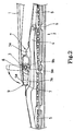
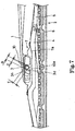
- 1 denotes a wiper arm made of a resin and the wiper arm, with the base end thereof fixed on a pivot shaft P which is provided on a vehicle main body, performs reciprocative wiping swings with the pivot shaft P as one body.
- a blade 2 is rotatably and detachably attached (supported) on the front end portion of the wiper arm 1, which will be described later.
- an attaching groove 3 whose lower side (the blade 2 side) is opened is formed in a condition where the groove inclines gradually toward the arm front end side on the lower side.
- a groove inner portion 3a located on the groove inner side of the said attaching groove 3 is formed into an inside cylindrical shape having a diameter R, while a first groove edge 3b on one side (front end side of the arm) which continues from the said attaching groove 3a is formed in a liner shape so as to coincide with a tangent line along the direction of the above-described inclination from the groove inner portion 3a.
- a second groove edge 3c on the other side is formed so that the position thereof shifts to the front end side beyond the position of the tangent line along the direction of the above-described inclination, and thus the groove width S of a groove entrance portion 3d is set to be smaller than the diameter R (R>S) and the dovetail groove shape is provided when the groove is viewed from the side.
- the blade 2 consists of members such as a primary lever 4 and a secondary lever 5 made of a resin, a blade rubber 6 and the like, and an attaching bracket 7, which is formed so as to surround the periphery of the primary lever 4, is fixed at the center portion in the longitudinal direction of the primary lever 4.
- an attaching bracket 7 which is formed so as to surround the periphery of the primary lever 4, is fixed at the center portion in the longitudinal direction of the primary lever 4.
- 9 denotes a spacer which, together with the fixed shaft 8, constructs a connecting shaft J of the present invention by being incorporated into the fixed shaft as described later.
- the spacer 9 is formed of a resin material and provided with a lever portion 9a which is adjacent to at least one attaching edge 7a of the attaching bracket 7 and a cylindrical sliding portion 9b which is formed on the base end portion of the said lever portion 9a in a protruded manner and fitted to the fixed shaft 8 so as to be slidable in the direction of shaft rotation.
- the spacer 9 turns (slides) around the sliding portion between the fixed shaft 8 and cylindrical sliding portion 9b as a turning fulcrum and is structured so that the swinging posture can be changed between a stand-up posture where the front end of the lever portion 9a is protruded from the attaching bracket in a stand-up manner and a collapsed posture where the front end of the lever portion 9a is stored in the attaching bracket 7.
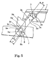
- the cylindrical sliding portion 9b has a cylindrical shape having an inner diameter X which is set to be the same as the diameter (outer diameter) of the fixed shaft 8 and an outer diameter R which is set to be the same as the diameter (inner diameter) R of the groove inner portion 3a of the attaching groove, and the thickness of the cylindrical sliding portion 9b is set to have a dimension of A/2.
- an opening 9c having a dimension Y which is narrower than the diameter X of the fixed shaft 8 (X>Y) is formed by notching on the cylindrical sliding portion 9b, and positional settings thereof are such that the outer circumference of the fixed shaft 8 is approximately in contact with an imaginary straight line L that connects both edges 9d of the said opening 9c with each other (that is, it may exactly be in contact with the imaginary straight line L or may slightly be deviated therefrom within a permissible range.)
- the outer circumference of the fixed shaft 8 is approximately in contact with the imaginary line L which is set by the opening 9c of the cylindrical sliding portion 9b and the fixed shaft 8 does not easily come off from the cylindrical sliding portion 9b, and thus the fixed shaft 8 and spacer 9 are incorporated with each other in a coming-off preventive manner.
- a chamfered portion 9e which is substantially based on the opening 9c of the cylindrical sliding portion 9b, is formed (created) on the outer circumference of the connecting shaft J, a larger diameter portion having an outer diameter R and the outer diameter at the said chamfered portion 9e, that is, a smaller diameter portion which is perpendicular to the imaginary straight line L and passes through the shaft core of the fixed shaft 8 are formed, and the dimension of the smaller diameter portion is set to have a diameter T which approximately coincides with the groove width S of the groove entrance portion 3d or is smaller than the same (T ⁇ S).
- the connecting shaft J is set so that when the lever portion 9a is brought into the collapsed posture, the opening 9c (the chamfered portion 9e) faces to the groove entrance portion 3d side of the attaching groove 3 and when the lever portion 9a is brought into the stand-up posture, the opening 9c faces to the side opposed to the first groove edge 3a of the attaching groove 3.
- a through hole which leads to the cylinder hole of the cylindrical sliding portion 9b and the opening 9c, is formed and a guide groove 9f, which is provided so as to open toward the same direction as the attaching groove 3a when the lever portion 9a is in the collapsed posture, is formed so as to lead to the above-described through hole.
- the groove width of the guide groove 9f is set so as to gradually widen toward the lower end (the side of the blade 2 when the lever portion 9a is in the collapsed posture).
- the spacer 9 is previously incorporated into the blade 2, which has not been attached to the wiper arm 1 yet, and for incorporation thereof, the groove end portion of the guide groove 9f is held against the fixed shaft 8 and in this state, the lever portion 9a is then pressed down, whereby the cylindrical sliding portion 9b is fitted and attached onto the fixed shaft 8 in a forcibly fitted manner.
- the spacer 9 is incorporated in the fixed shaft 8 in a state where it is prevented from coming off in the outer diameter direction and set so that the connecting shaft J having the chamfered portion 9e formed on the outer circumference thereof is constructed.
- the spacer 9 is incorporated in the fixed shaft 8 of the blade 2, which is refered to a connecting shaft J having the chamfered portion 9e formed on the outer circumference thereof. Then, the lever portion 9a of the spacer 9 is brought into a stand-up posture and set so that the chamfered portion 9e (the opening 9c of the cylindrical sliding portion 9b) faces to the side of the first groove edge 3b of the wiper arm attaching groove 3. Then, as shown in Fig. 5, the spacer thus set is approximated to the groove entrance portion 3d of the wiper arm attaching groove 3 and the chamfered portion 9e of the connecting shaft J and the liner first groove edge 3b of the attaching groove are opposed to each other.
- the smaller diameter portion of the connecting shaft J having a small diameter T is opposed to the groove entrance portion 3d having a groove width S which is equal to the small diameter T or is greater than the same, and a setting is provided so that the connecting shaft J is inserted along the first groove edge 3b (the position shown by the imaginary lines of Fig. 6(A)) and then inserted while the position being shifted toward the base end side of the wiper arm 1, whereby as shown by the solid lines of the Fig. 6(A), the connecting shaft can be fitted with the groove inner portion 3a.
- a setting is provided so that when the lever portion 9a is brought into a stand-up posture, the connecting shaft J can be fitted to the groove inner portion 3a by only an operation to insert (only to stick) the connecting shaft into the attaching groove 3, and the relationship between the attaching groove 3 and connecting shaft J in such a condition corresponds to an attaching and detaching posture of the present invention.
- wiping-off operation for the window surface are performed by the blade 2 in this state.
- the blade 2 since curvature exists on the window surface, the blade 2 performs wiping-off while minutely swinging with respect to the wiper arm 1 and on the other hand, the wiper arm is urged toward the window surface side by an urging spring (which is not illustrated). Therefore, smooth sliding is required at the portion where the attaching groove 3 and the connecting shaft J are connected and it becomes necessary for the said smooth sliding to secure a large area where one makes contact with the other.
- the spacer 9 is integrated into the attaching groove 3 side, when the blade 2 swings, sliding is performed between the inner circumferential surface of the spacer cylindrical sliding portion 9b and fixed shaft 8.
- the groove shape of the attaching groove 3 is set so that the chamfered portion 9e is opposed to the groove entrance portion 3d of the attaching groove, therefore a pressure force which the fixed shaft 8 receives from the window surface side based on the urging spring does not act on the opening 9c side (but acts on the side opposite to the opening).
- the state where the chamfered portion 9e is opposed to the groove entrance portion 3d of the attaching groove indicates that the connected portion between the fixed shaft 8 and cylindrical sliding portion 9b is opposed to the opening portion of the groove entrance portion 3d, however, as mentioned before, since the fixed shaft 8 and the cylinder sliding portion 9b are in a coming-off preventive condition and the lever portion 9a is also incorporated in a forcibly fitted manner, the wiper arm 1 and the blade 2 do not easily come apart in this condition .
- the spacer 9 may be incorporated into the attaching bracket 7 of the blade 2 so as to be incorporated into the blade 2 side.
- the blade 2 swings, whereby sliding is performed between the outer circumferential surface of the spacer cylindrical sliding portion 9a and the inner circumferential surface of the attaching groove 3.
- the lever portion 9a of the spacer 9 incorporated in the fixed shaft 8 of the blade 2 is brought into a stand-up posture and the chamfered portion 9e of the connecting shaft J (the opening 9c of the cylindrical sliding portion 9b) is faced toward the first groove edge 3b side of the wiper arm attaching groove 3 and an attaching and detaching posture is produced.
- the smaller diameter portion having a small diameter T which can be inserted in the groove width S of the groove entrance portion 3d of the attaching groove 3 is opposed to the connecting shaft J, attachment and detachment between the connecting shaft J and attaching groove 3 can be easily performed by only inserting and drawing out the shaft, and no fitting load acts on the attaching groove 3 and the connecting shaft J. Consequently, operations for attaching and detaching the blade 2 to and from the wiper arm 1 becomes easy, while the blade 2 in an attached condition is securely attached to the wiper arm 1, thereby improving workability during replacement of the blade 2.
- no load acts on the attaching and detaching operation even if a wiper arm 1 made of resin is used, no defect exists such that the attaching groove 3 is worn, durability of the product can be improved, and reliability thereof can be enhanced.
- a setting is provided such that when the attaching groove 3 and the connecting shaft J are brought in the connected posture, the chamfered portion 9e is opposed to the groove entrance portion 3d, that is, a setting is provided such that the spacer opening 9c is opposed to the groove entrance 3d of the attaching groove, and furthermore, the spacer 9 is incorporated in the wiper arm 1 side. Therefore, as a slight swing of the blade 2, sliding movement is performed in response to a contact area which is widely secured between the spacer cylindrical sliding portion 9b and the fixed shaft 8 and stable swings can be performed.
- the pressure force by the urging spring on the wiper arm 1 side acts on the widely secured sliding surface but does not act on the chamfered portion 9b and spacer opening 9c, therefore the cylindrical sliding portion 9b effectively functions as a bearing and the swinging actions of the blade 2 can be smoothly performed.
- the chamfered portion 9e of the connecting shaft J is opposed to the first groove edge 3b of the attaching groove without operation of the spacer lever portion 9a and, as a result, the connecting shaft J comes off from the attaching groove 3.
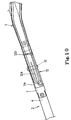
- the counterclockwise swing of the blade 2 is restricted so as not to be carried out by approximately 90°by bringing the primary lever 4 on the blade 2 side into contact with the wiper arm 1. Accordingly, for example, even in a case where the wiper arm 1 lying on the window surface is raised and the blade 2 is made to swing during a car wash, a defect such that the blade unexpectedly comes apart from the wiper arm 1 can be securely prevented. In addition, during the clockwise swing of the blade 2, the blade 2 does not come apart from the wiper arm 1.
- the present invention is not limited to the above-described embodiment, and as mentioned before, a construction may also be employed, wherein the connecting shaft on which the chamfered portion is formed is fixed to the blade as one body and the wiper arm is made to turn (swing) so that the posture of the attaching groove can be changed with respect to the said fixed connecting shaft.
- the positional relationship between the chamfered portion of the connecting shaft and the groove entrance portion of the attaching groove is important, and as a matter of course, a setting is provided so that the attaching groove and connecting shaft maintain the connected posture within the swinging range of the wiper arm and blade and change into an attaching and detaching posture based on a swing exceeding the said swinging range.
- a connecting shaft 10 of the second embodiment has an outer diameter equivalent to the inner diameter R of the groove inner portion 3a of the attaching groove 3 and a chamfered portion 10a is provided on the outer circumference, whereby a smaller diameter portion having a diameter which is equal to the groove width S of the groove entrance portion 3d or equivalent to the diameter T that is smaller than the groove width S.
- connecting shaft 10 is supported on the attaching bracket 7 of the blade 2 side so as to be slidable in the direction of shaft rotation.
- a pincher (which corresponds to an adjusting member of the present invention) 10b is formed on one end portion of the connection shaft 10 as one body.
- the pincher 10b is arranged so as to be exposed outside the attaching bracket attaching edge 7a, the connecting shaft 10 can be slid in the direction of shaft rotation by turning and operating the pincher 10b, thus the postural relationship between the attaching groove 3 and connecting shaft 10 can be changed into a connected posture and an attaching and detaching posture.
- a posture retaining means (which is not illustrated) is releasably provided in the pincher 10 and retains the connecting shaft 10 in a connected posture.
- the posture retaining means is released and the pincher 10b is turned so as to produce an attaching and detaching posture, whereby making it possible to easily detach the blade 2.
- advantages thereof are the same as those of the first embodiment.
- a groove entrance portion 3d having a groove width M slightly smaller in diameter than the inner diameter R of the groove inner portion 3a is formed on the attaching groove 3 of the present embodiment. Therefore, in order to make the attaching groove 3 support a cylindrical fixed shaft 11 having an outer diameter which is the same as the inner diameter R of the groove inner portion 3a, fitting and supporting can be performed by light press fitting. Since the fixed shaft 11 in such a lightly press-fitted condition can be easily fitted into the attaching groove 3, coming-off thereof is also easy, and such a condition corresponds to the attaching and detaching posture of the present invention.
- 12 denotes a stopper pin and the stopper pin 12 can be formed by turning up and bending a resilient steel material and a stopper portion 12a which is one of the turned-up portions is urged in the direction where the tumed-up portions come close to each other. Then, the stopper pin 12 is attached by inserting it from the front end side of the wiper arm 1 while forcibly expanding the stopper portion 12a, and the stopper portion 12a, which penetrates through a rib 3e formed on the attaching groove 3, is brought into contact, in a pressured manner, with the outer circumference of the fixed shaft 11, which is exposed from the groove entrance portion 3d of the attaching groove 3.
- the stopper portion 12a in a condition where an urging force is applied is brought into contact with the fixed shaft 11 and prevents the fixed shaft 11 from coming off from the attaching groove 3.
- the connecting shaft comprises the fixed shaft 11 and the stopper pin 12, and the condition where the stopper pin 12 is attached and coming-off is prevented corresponds to the connected posture of the present invention.
- 12b denotes an engaging portion for fixing the stopper pin 12 on the wiper arm 1, and by engaging and supporting the said engaging portion 12b on the wiper arm 1, the stopper pin 12 is fixed so as to be resiliently held between the wiper arm 1 and blade 2.
- the resilience of the stopper pin 12 is set to an extent that the blade 2 is not hindered from swinging with respect to the wiper arm 1 around the fixed shaft 11 as a fulcrum.
- the relationship between the attaching groove 3 and a connecting shaft (the fixed shaft 11 and the stopper pin 12) can be changed into a connected posture and an attaching and detaching posture.
- replacing operations of the blade can be simplified and construction where no load is applied to the attaching groove 3 can improve durability, while the wiper arm 1 and the blade 2 can be securely attached.
- the attaching groove 3 and the fixed shaft 11 according to the present embodiment have the same structure as that of the third embodiment, the groove entrance portion 3d having a groove width M which is slightly smaller in diameter than the inner diameter R of the groove inner portion 3a is formed, and the fixed shaft 11 can be fitted and supported on the attaching groove 3 by light press-fitting.
- the fixed shaft 11 can be easily attached and detached to and from the attaching groove 3 corresponds to the attaching and detaching posture of the present invention.
- a connected posture is produced between the attaching groove 3 and the fixed shaft 11 by attaching a stopper pin 13.
- the stopper pin 13 of the present embodiment is formed of a plate-like steel material and inserted from the front end side of the wiper arm 1 via the rib 3e, thus the inserted front end portion prevents the fixed shaft 11 which faces to the groove entrance portion 3d from coming off, and the stopper pin 13 is fixed to the wiper arm 1 by rotating to engage an engaging projection 13a, which is bent and formed on the front end portion of the stopper pin 13, with the rib 3b after setting the stopper pin 13.
- Such a condition where the stopper pin 13 prevents the fixed shaft 11 from coming off corresponds to the connected posture between the attaching groove 3 and connecting shaft (fixed shaft 11 and stopper pin 13) according to the present invention.
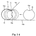
- An attaching groove 14 formed on the wiper arm 1 of the preset embodiment is formed similarly to that of the above-described embodiments. That is, an attaching groove 14a located on the groove inner side is formed in an inside cylindrical shape having a diameter R and the said inside cylindrical shape is closer to a cylinder than a semi-cylinder by a portion equivalent to the chord H.
- a first groove edge 14b which leads to a groove inner portion 14a of the attaching groove coincides with a tangent line at one end portion of the groove inner portion 14a
- a second groove edge 14c on the other side is formed from the other end portion so as to expand and open obtusely, whereby the groove width S of a groove entrance portion 14d becomes smaller than the inner diameter R of the groove inner portion 14a (R>S), and thus the attaching groove 14 has a dovetail groove shape when the groove is viewed from the side.
- the chord H is set so as to become smaller than the groove width S of the groove entrance portion 14d (H ⁇ S).
- a connecting shaft 15 has a columnar shape having an outside diameter approximately equal to the inner diameter R of the groove inner portion 14a of the attaching groove and a long dent groove 15a is formed on the outer circumferential surface in the shaft direction, and the said connecting shaft 15 is attached to the blade 2.
- the dent groove 15a is formed to have an approximately arc-shaped groove surface, dimensions are set so that the groove width N in the circumferential direction becomes grater than the chord H which corresponds to a portion exceeding a semi-cylinder of the attaching groove 14 (N ⁇ H) and the maximum depth D of the groove depth becomes smaller than the groove width S of the groove entrance portion 14d of the attaching groove 14 (D ⁇ S).
- the dent groove 15a is not limited to having an arc-shape as long as it is provided with the groove width of N and the maximum groove depth of D and an appropriate shape, for example, a V-groove, a rectangular groove or the like can be employed.
- the connecting shaft 15 on the blade 2 side is held against a connecting shaft dent groove 15a in a condition where a corner portion C of the second groove edge 14c side of the groove entrance portion 14d on the wiper arm 1 side is fitted.
- the connecting shaft 15 is then rotated relatively with respect to the attaching groove 14 (in the direction of arrow P) to change the posture of the dent groove 15a opposed to the corner portion C, while the connecting shaft 15 is shifted toward the groove inner portion 14a side (in the direction of arrow Q), and whereby connection between the connecting shaft 15 and the attaching groove 14 is accomplished.
- the attaching and detaching operations of the connecting shaft 15 with respect to the attaching groove 14 becomes easy, the replacement operation of the blade 2 becomes easy, and furthermore, no load acts on the attaching groove 14 during the said replacement operation, thus making it possible to improve durability.
- the dent grove 15a can be set so as to be located at the groove entrance portion 14d. If such a setting is employed, the outer circumferential surface of the connecting shaft 15 slides beyond the whole inner circumferential surface of the groove inner portion 14a in a manner of surface contact.
- the groove width N of the dent groove 15a of the connecting shaft 15 is set to be equal to or slightly greater than the chord H and the said chord H is also set to be smaller than the groove width S of the groove entrance portion 14d in the present embodiment, whereby the sliding surface of the connecting shaft 15, that is, the outer circumferential surface excluding the dent groove 15a can be secured to be longer than the sliding surface which is set by the groove inner portion 14a.
- the connecting shaft 15 of the present embodiment is fixedly attached to the attaching bracket 7 of the blade 2 and when the connecting shaft 15 is attached and detached to and from the wiper arm attaching groove 14, the attaching and detaching operation is performed while the posture of the wiper arm 1 or the blade 2 is changed.
- a structure may be employed such that the connecting shaft 15 is slidably incorporated into the attaching bracket 7, and an embodiment of this case can be carried out by providing, for example, a pincher on one end portion in the shaft direction of the connecting shaft 15 so as to protrude outside the attaching bracket 7 and then performing the attaching and detaching operation while rotating the said pincher.
- the connecting shaft can be securely connected to the attaching groove.
- the attaching and detaching operations be simplified but also it becomes possible to prevent an attaching and detaching load from being applied to the attaching groove.
Landscapes
- Engineering & Computer Science (AREA)
- Mechanical Engineering (AREA)
- Ink Jet (AREA)
Abstract
Description
as the attaching groove, a groove inner portion having a large diameter and a groove entrance portion having a width narrower than the said groove inner portion are formed and the posture of the attaching groove and the connecting shaft is changed to a connected posture where a coming-off prevention is carried out from the groove entrance portion and to an attaching and detaching posture where entry and exit can be freely carried out from the groove entrance portion.
Claims (6)
- A blade attaching structure of a wiper unit, comprising an attaching groove formed on the tip end of a wiper arm; and a connecting shaft provided on a blade for wiping a window surface, the connecting shaft detachably and rotatably supported by the attaching groove, whereinthe attaching groove is provided with a groove inner portion having a larger diameter and a groove entrance portion having a width narrower than the groove inner portion andpostures of the attaching groove and the connecting shaft are changed between a connected posture where the connecting shaft is prevented from coming off from the groove entrance portion and attaching and detaching postures where the connecting shaft can freely enter or exit from the groove entrance portion.
- The blade attaching structure of the wiper unit as set forth in claim 1, whereinthe connecting shaft is supported on the blade so as to be slidable in a rotational direction of the shaft, the connecting shaft having a larger diameter portion and a smaller diameter portion due to a chamfered portion created on the outer circumference andchanging postures are accomplished by operating an adjusting member integrally formed on the connecting shaft end portion to make the connecting shaft slide in the rotational direction of the shaft.
- The blade attaching structure of the wiper unit as set forth in claim 1, whereinthe connecting shaft comprises a larger diameter portion and a smaller diameter portion formed by externally fitting a cylindrical sliding portion having a chamfered portion formed on the outer circumference to a fixed shaft integrally fixed to the blade so as to be slidable in a rotational direction of the shaft andchanging postures are accomplished based on the slide of the cylindrical sliding portion in the rotational direction of the shaft.
- The blade attaching structure of the wiper unit as set forth in claim 1, whereinthe connecting shaft is integrally fixed to the blade, the connecting shaft having a larger diameter portion and a smaller diameter portion formed due to a chamfered portion created on the outer circumference andchanging postures are accomplished based on changing the postures of the attaching groove by rotating the wiper arm with respect to the blade.
- The blade attaching structure of the wiper unit as set forth in claim 1, wherein the connecting shaft is attached to the blade, the connecting shaft having a long concave groove on the outer circumference in the axial direction and
the attaching and detaching postures enable free entrance and exit of the connecting shaft with respect to the groove inner portion by rotating the connecting shaft in such a state that the groove entrance portion is fitted in the concave groove. - The blade attaching structure of the wiper unit as set forth in claim 1, wherein the groove width of the groove entrance portion of the attaching groove is made slightly smaller than the inner diameter of the groove inner portion, while the connecting shaft comprises a fixed shaft integrally fixed to the blade and a stopper pin for preventing the fixed shaft internally fitted to the groove inner portion from coming off at the groove entrance portion and the attaching groove and the connecting shaft are changed in posture based on attachment and detachment of the stopper pin.
Applications Claiming Priority (3)
| Application Number | Priority Date | Filing Date | Title |
|---|---|---|---|
| JP10398099 | 1999-04-12 | ||
| JP10398099 | 1999-04-12 | ||
| PCT/JP2000/002175 WO2000061409A1 (en) | 1999-04-12 | 2000-04-04 | Blade mounting structure of wiper device |
Publications (2)
| Publication Number | Publication Date |
|---|---|
| EP1190921A1 true EP1190921A1 (en) | 2002-03-27 |
| EP1190921A4 EP1190921A4 (en) | 2009-04-22 |
Family
ID=14368478
Family Applications (1)
| Application Number | Title | Priority Date | Filing Date |
|---|---|---|---|
| EP00913098A Withdrawn EP1190921A4 (en) | 1999-04-12 | 2000-04-04 | Blade mounting structure of wiper device |
Country Status (3)
| Country | Link |
|---|---|
| US (1) | US6859985B1 (en) |
| EP (1) | EP1190921A4 (en) |
| WO (1) | WO2000061409A1 (en) |
Cited By (1)
| Publication number | Priority date | Publication date | Assignee | Title |
|---|---|---|---|---|
| CN104890639A (en) * | 2015-05-13 | 2015-09-09 | 丹阳镇威汽配有限公司 | Multifunctional sheath mechanism for windshield wiper |
Families Citing this family (20)
| Publication number | Priority date | Publication date | Assignee | Title |
|---|---|---|---|---|
| JP3445530B2 (en) | 1999-06-11 | 2003-09-08 | アスモ株式会社 | Vehicle wiper |
| JP4502470B2 (en) * | 2000-07-12 | 2010-07-14 | 株式会社ミツバ | Blade mounting structure in wiper device |
| USD545752S1 (en) * | 2003-10-24 | 2007-07-03 | Federal Mogul, S.A. | Windscreen wiper blade combination-element |
| US7543454B2 (en) * | 2005-03-14 | 2009-06-09 | Zero Emission Systems, Inc. | Method and auxiliary system for operating a comfort subsystem for a vehicle |
| DE102005050773A1 (en) * | 2005-10-24 | 2007-04-26 | Robert Bosch Gmbh | Windscreen wiper device and method for operating a windscreen wiper device |
| US8166604B2 (en) * | 2009-01-30 | 2012-05-01 | Honda Motor Co., Ltd. | Apparatus for preventing unintentional wiper blade removal |
| JP5545864B2 (en) * | 2010-10-15 | 2014-07-09 | アスモ株式会社 | Wiper blade |
| US9457768B2 (en) | 2011-04-21 | 2016-10-04 | Pylon Manufacturing Corp. | Vortex damping wiper blade |
| US9174609B2 (en) | 2011-04-21 | 2015-11-03 | Pylon Manufacturing Corp. | Wiper blade with cover |
| WO2013016493A1 (en) | 2011-07-28 | 2013-01-31 | Pylon Manufacturing Corp. | Windshield wiper adapter, connector and assembly |
| US9108595B2 (en) | 2011-07-29 | 2015-08-18 | Pylon Manufacturing Corporation | Windshield wiper connector |
| KR101350275B1 (en) * | 2011-11-09 | 2014-01-23 | 케이씨더블류 주식회사 | Wiper blade |
| CA2865292C (en) | 2012-02-24 | 2018-03-13 | Pylon Manufacturing Corp. | Wiper blade |
| US20130219649A1 (en) | 2012-02-24 | 2013-08-29 | Pylon Manufacturing Corp. | Wiper blade |
| US10829092B2 (en) | 2012-09-24 | 2020-11-10 | Pylon Manufacturing Corp. | Wiper blade with modular mounting base |
| US10166951B2 (en) | 2013-03-15 | 2019-01-01 | Pylon Manufacturing Corp. | Windshield wiper connector |
| JP6084137B2 (en) * | 2013-08-28 | 2017-02-22 | アスモ株式会社 | Vehicle wiper |
| US9505380B2 (en) | 2014-03-07 | 2016-11-29 | Pylon Manufacturing Corp. | Windshield wiper connector and assembly |
| USD777079S1 (en) | 2014-10-03 | 2017-01-24 | Pylon Manufacturing Corp. | Wiper blade frame |
| JP6620071B2 (en) * | 2016-06-23 | 2019-12-11 | 株式会社松本製作所 | Wiper blade |
Family Cites Families (16)
| Publication number | Priority date | Publication date | Assignee | Title |
|---|---|---|---|---|
| DE44399C (en) * | G. E. WOLFF in Hamburg, St. Georg, Langereihe 59 | Adjustable drilling and milling machine with rotatable tool head | ||
| US2404523A (en) * | 1945-03-20 | 1946-07-23 | Max Zaiger | Connector for windshield wiper arms |
| DE1200704B (en) * | 1958-07-16 | 1965-09-09 | Italiana Magneti Marelli Soc P | Attachment of the wiper blade to the wiper arm for windshield wipers |
| US3576044A (en) * | 1968-02-05 | 1971-04-27 | Sev Marchal | Means for attaching the arm of a windshield wiper to the blade support thereof |
| US3659309A (en) * | 1969-01-30 | 1972-05-02 | Sev Marchal | Means for attaching the arm of a windshield wiper to the blade support thereof |
| FR2475481B1 (en) * | 1980-02-13 | 1985-07-05 | Archambel Sa | CONNECTOR FOR WIPER BLADE |
| FR2486002B1 (en) * | 1980-07-07 | 1985-06-21 | Marchal Equip Auto | WINDSCREEN WIPER COMPRISING AN ADD-ON ARM, IN PARTICULAR FOR A MOTOR VEHICLE |
| IT1144856B (en) * | 1981-05-29 | 1986-10-29 | Arman Spa | DEVICE FOR CONNECTING A WINDSCREEN WIPER TO A WINDSCREEN WIPER ARM |
| IT8153356V0 (en) * | 1981-06-12 | 1981-06-12 | Arman Spa | SUPPORTING STRUCTURE FOR BRACKET FOR WINDSCREEN WIPERS |
| DE3331310A1 (en) * | 1983-08-31 | 1985-03-14 | SWF Auto-Electric GmbH, 7120 Bietigheim-Bissingen | Wiper lever, in particular for motor vehicles |
| GB8525590D0 (en) * | 1985-10-17 | 1985-11-20 | Trico Folberth Ltd | Windscreen |
| FR2614854B1 (en) * | 1987-05-06 | 1991-02-15 | Marchal Equip Auto | CONNECTOR DEVICE FOR MOUNTING A WIPER BLADE CALIPER, AND CALIPER PROVIDED WITH SUCH A CONNECTOR DEVICE |
| JPH09272406A (en) * | 1996-04-05 | 1997-10-21 | Asmo Co Ltd | Shape of clip for wiper blade |
| US5885023A (en) * | 1996-11-08 | 1999-03-23 | Cooper Automotive Products, Inc. | Windshield wiper blade connector |
| DE29712293U1 (en) * | 1997-07-11 | 1998-11-05 | Robert Bosch Gmbh, 70469 Stuttgart | Wiper blade for windows of motor vehicles |
| DE19729865A1 (en) * | 1997-07-11 | 1999-01-14 | Bosch Gmbh Robert | Windshield wipers for motor vehicles |
-
2000
- 2000-04-04 US US09/937,626 patent/US6859985B1/en not_active Expired - Fee Related
- 2000-04-04 WO PCT/JP2000/002175 patent/WO2000061409A1/en not_active Ceased
- 2000-04-04 EP EP00913098A patent/EP1190921A4/en not_active Withdrawn
Cited By (1)
| Publication number | Priority date | Publication date | Assignee | Title |
|---|---|---|---|---|
| CN104890639A (en) * | 2015-05-13 | 2015-09-09 | 丹阳镇威汽配有限公司 | Multifunctional sheath mechanism for windshield wiper |
Also Published As
| Publication number | Publication date |
|---|---|
| EP1190921A4 (en) | 2009-04-22 |
| WO2000061409A1 (en) | 2000-10-19 |
| US6859985B1 (en) | 2005-03-01 |
Similar Documents
| Publication | Publication Date | Title |
|---|---|---|
| US6859985B1 (en) | Blade attaching structure of wiper unit | |
| JP4076163B2 (en) | Windshield wiper with wiper arm | |
| JP4343827B2 (en) | Front glass window cleaner | |
| JP2001500090A (en) | Wiper device used for windshield glass of automobiles | |
| US20100237564A1 (en) | Mechanical Seal | |
| JP6084137B2 (en) | Vehicle wiper | |
| KR100463320B1 (en) | A wiper blade and a method of manufacturing a wiper blade | |
| EP1147955A2 (en) | Wiper blade | |
| JP2001505850A (en) | Windshield wiper | |
| JPH07329730A (en) | Vehicle wiper | |
| US6594854B1 (en) | Wiper device having wiper blade easily attachable to and detachable from wiper arm | |
| JP2006327589A (en) | Wiper blade | |
| CN103118907B (en) | Windscreen wiper device | |
| JP4276606B2 (en) | Vehicle wiper | |
| JPS6317658B2 (en) | ||
| JP3445530B2 (en) | Vehicle wiper | |
| JP5084500B2 (en) | Joint device between wiper lever and wiper lever support, and wiper arm comprising such a joint device | |
| JP4351972B2 (en) | Pantograph type jack | |
| JP4779867B2 (en) | Wiper device | |
| JP2007314053A (en) | Wiper arm and wiper device | |
| JPWO2000061409A1 (en) | Blade mounting structure for wiper device | |
| JP2001080469A (en) | Wiper structure | |
| JP2602040Y2 (en) | Vehicle wiper blade | |
| JP2005297940A (en) | Wiper blade | |
| JP4042294B2 (en) | Wiper blade for vehicle |
Legal Events
| Date | Code | Title | Description |
|---|---|---|---|
| PUAI | Public reference made under article 153(3) epc to a published international application that has entered the european phase |
Free format text: ORIGINAL CODE: 0009012 |
|
| 17P | Request for examination filed |
Effective date: 20011024 |
|
| AK | Designated contracting states |
Kind code of ref document: A1 Designated state(s): AT BE CH CY DE DK ES FI FR GB GR IE IT LI LU MC NL PT SE |
|
| REG | Reference to a national code |
Ref country code: DE Ref legal event code: 8566 |
|
| RBV | Designated contracting states (corrected) |
Designated state(s): FR GB |
|
| A4 | Supplementary search report drawn up and despatched |
Effective date: 20090319 |
|
| STAA | Information on the status of an ep patent application or granted ep patent |
Free format text: STATUS: THE APPLICATION IS DEEMED TO BE WITHDRAWN |
|
| 18D | Application deemed to be withdrawn |
Effective date: 20090622 |