EP1190920A1 - Wiper device - Google Patents
Wiper device Download PDFInfo
- Publication number
- EP1190920A1 EP1190920A1 EP01917847A EP01917847A EP1190920A1 EP 1190920 A1 EP1190920 A1 EP 1190920A1 EP 01917847 A EP01917847 A EP 01917847A EP 01917847 A EP01917847 A EP 01917847A EP 1190920 A1 EP1190920 A1 EP 1190920A1
- Authority
- EP
- European Patent Office
- Prior art keywords
- recess
- pivot
- angle
- shaft
- wiper device
- Prior art date
- Legal status (The legal status is an assumption and is not a legal conclusion. Google has not performed a legal analysis and makes no representation as to the accuracy of the status listed.)
- Granted
Links
Images


Classifications
-
- B—PERFORMING OPERATIONS; TRANSPORTING
- B60—VEHICLES IN GENERAL
- B60S—SERVICING, CLEANING, REPAIRING, SUPPORTING, LIFTING, OR MANOEUVRING OF VEHICLES, NOT OTHERWISE PROVIDED FOR
- B60S1/00—Cleaning of vehicles
- B60S1/02—Cleaning windscreens, windows or optical devices
- B60S1/04—Wipers or the like, e.g. scrapers
- B60S1/32—Wipers or the like, e.g. scrapers characterised by constructional features of wiper blade arms or blades
- B60S1/34—Wiper arms; Mountings therefor
-
- B—PERFORMING OPERATIONS; TRANSPORTING
- B60—VEHICLES IN GENERAL
- B60S—SERVICING, CLEANING, REPAIRING, SUPPORTING, LIFTING, OR MANOEUVRING OF VEHICLES, NOT OTHERWISE PROVIDED FOR
- B60S1/00—Cleaning of vehicles
- B60S1/02—Cleaning windscreens, windows or optical devices
- B60S1/04—Wipers or the like, e.g. scrapers
- B60S1/0413—Modular wiper assembly
- B60S1/0422—Modular wiper assembly having a separate transverse element
- B60S1/0425—Modular wiper assembly having a separate transverse element characterised by the attachment of the wiper shaft holders to the transverse element
-
- B—PERFORMING OPERATIONS; TRANSPORTING
- B60—VEHICLES IN GENERAL
- B60S—SERVICING, CLEANING, REPAIRING, SUPPORTING, LIFTING, OR MANOEUVRING OF VEHICLES, NOT OTHERWISE PROVIDED FOR
- B60S1/00—Cleaning of vehicles
- B60S1/02—Cleaning windscreens, windows or optical devices
- B60S1/04—Wipers or the like, e.g. scrapers
- B60S1/043—Attachment of the wiper assembly to the vehicle
- B60S1/0433—Attachement of a wiper modular assembly to the vehicle
-
- Y—GENERAL TAGGING OF NEW TECHNOLOGICAL DEVELOPMENTS; GENERAL TAGGING OF CROSS-SECTIONAL TECHNOLOGIES SPANNING OVER SEVERAL SECTIONS OF THE IPC; TECHNICAL SUBJECTS COVERED BY FORMER USPC CROSS-REFERENCE ART COLLECTIONS [XRACs] AND DIGESTS
- Y10—TECHNICAL SUBJECTS COVERED BY FORMER USPC
- Y10T—TECHNICAL SUBJECTS COVERED BY FORMER US CLASSIFICATION
- Y10T29/00—Metal working
- Y10T29/49—Method of mechanical manufacture
- Y10T29/49826—Assembling or joining
- Y10T29/49906—Metal deforming with nonmetallic bonding
-
- Y—GENERAL TAGGING OF NEW TECHNOLOGICAL DEVELOPMENTS; GENERAL TAGGING OF CROSS-SECTIONAL TECHNOLOGIES SPANNING OVER SEVERAL SECTIONS OF THE IPC; TECHNICAL SUBJECTS COVERED BY FORMER USPC CROSS-REFERENCE ART COLLECTIONS [XRACs] AND DIGESTS
- Y10—TECHNICAL SUBJECTS COVERED BY FORMER USPC
- Y10T—TECHNICAL SUBJECTS COVERED BY FORMER US CLASSIFICATION
- Y10T29/00—Metal working
- Y10T29/49—Method of mechanical manufacture
- Y10T29/49826—Assembling or joining
- Y10T29/49908—Joining by deforming
- Y10T29/49925—Inward deformation of aperture or hollow body wall
- Y10T29/49927—Hollow body is axially joined cup or tube
- Y10T29/49929—Joined to rod
- Y10T29/49931—Joined to overlapping ends of plural rods
-
- Y—GENERAL TAGGING OF NEW TECHNOLOGICAL DEVELOPMENTS; GENERAL TAGGING OF CROSS-SECTIONAL TECHNOLOGIES SPANNING OVER SEVERAL SECTIONS OF THE IPC; TECHNICAL SUBJECTS COVERED BY FORMER USPC CROSS-REFERENCE ART COLLECTIONS [XRACs] AND DIGESTS
- Y10—TECHNICAL SUBJECTS COVERED BY FORMER USPC
- Y10T—TECHNICAL SUBJECTS COVERED BY FORMER US CLASSIFICATION
- Y10T403/00—Joints and connections
- Y10T403/49—Member deformed in situ
-
- Y—GENERAL TAGGING OF NEW TECHNOLOGICAL DEVELOPMENTS; GENERAL TAGGING OF CROSS-SECTIONAL TECHNOLOGIES SPANNING OVER SEVERAL SECTIONS OF THE IPC; TECHNICAL SUBJECTS COVERED BY FORMER USPC CROSS-REFERENCE ART COLLECTIONS [XRACs] AND DIGESTS
- Y10—TECHNICAL SUBJECTS COVERED BY FORMER USPC
- Y10T—TECHNICAL SUBJECTS COVERED BY FORMER US CLASSIFICATION
- Y10T403/00—Joints and connections
- Y10T403/57—Distinct end coupler
- Y10T403/5706—Diverse serial connections
Definitions
- the present invention relates to wiper devices that wipe vehicle windows.
- a wiper device of a vehicle includes a wiper arm attached to a pivot shaft.
- the pivot shaft pivots the wiper arm in a predetermined angular range to wipe a window.
- Japanese Unexamined Patent Publication No. 8-156747 discloses a module type wiper device with a pair of wiper arms that move synchronously.
- This wiper device includes a pair of pivot holders each of which support a pivot shaft.
- a pipe frame connects the pivot holders to each other.
- the wiper arms are attached to the associated pivot shafts.
- each pivot holder includes a fitting portion 110 that is fitted in a pipe frame 100.
- Eight recesses 111 are formed in the outer side of the fitting portion 110. That is, four recesses 111 are spaced from the remaining four recesses 111 at predetermined intervals in an axial direction of the fitting portion 110.
- Each recess 111 forms a pair with one of the recesses 111 that are axially spaced.
- a pair of press dies 120 with a plurality of pressing portions 121 that correspond to the recesses 111 are prepared. After the fitting portion 110 is fitted in the pipe frame 100, the pressing portions 121 of each press die 120 press the outer side of the pipe frame 100. This deforms a portion of the pipe frame 100 that corresponds to each recess 111 such that the deformed portion enters the recess 111, thus securing the pivot holder to the pipe frame 100.
- the two corresponding recesses 111 that are spaced from each other in an axial direction of the fitting portion 110 each have a side wall 111a.
- the side walls 111a of these recesses 111 face in opposite directions and are parallel with each other.
- the two corresponding recesses 111 adjacent to each other in a circumferential direction of the fitting portion 110 each have a side wall 111b.
- the side walls 111b of these recesses 111 face in opposite directions and are parallel with each other.
- the side walls 111a, 111b are parallel with a movement direction of each press die 120.
- the molds must be separated from each other in a direction parallel with the side walls 111a, 111b for isolating the pivot holder from the molds.
- it is complicated to design and fabricate the molds such that a separating direction of each mold is precisely parallel with the side walls 111a, 111b. Further, the designing of the molds is restricted.
- a caulking portion of the pipe frame 100 must be in secure contact with the inner wall of each recess 111.
- a cross-sectional shape of each recess 111 in an axial direction of the fitting portion 110 is rectangular. That is, a corner portion of the inner wall of each recess 111 (in Fig. 9, a corner portion between each side wall 111a and the bottom of the recess 111) is relatively squared. The corner portions of each pressing portion 121 thus must be relatively squared to ensure that the caulking portion of the pipe frame 100 is in secure contact with the inner wall of each recess 111.
- each pressing portion 121 plastically deforms the pipe frame 100
- reactive force may act focally on a portion of the pipe frame 100 that corresponds to each corner portion of the pressing portion 121, thus causing a crack.
- the corner portions of each pressing portion 121 quickly wear, and a desired securing strength of the pressing portion 121 is hampered at an early stage.
- each pivot holder In a wiper device disclosed in Japanese Unexamined Patent Publication No. 5-32153, two pivot holders are each secured to an end of a pipe frame through a bolt.
- Each pivot holder has a shaft hole that receives a pivot shaft and a through hole through which the bolt is passed.
- the axis of the shaft hole is parallel with the axis of the through hole.
- each pivot holder can be isolated from a pair of molds, which form the pivot holder, by separating the molds from each other along the axis of the shaft hole and the axis of the through hole, when molding is completed.
- the molds must be designed and fabricated with high accuracy such that a movement direction of each mold, the axis of the shaft hole, and the axis of the through hole are completely parallel with one another. Like the prior art shown in Figs. 8 and 9, this complicates the fabrication of the molds and restricts the designing of the same. Further, as long as the axis of the shaft hole is parallel with the axis of the through hole, the pivot holder cannot be generally used. In addition, it is troublesome to secure each pivot holder to the pipe frame through the bolt.
- a wiper device includes a pair of pivot holders each including a fitting portion that extends along a fitting axis, a pivot shaft that is rotationally supported by each pivot holder, and a frame that connects the pivot holders to each other.
- a plurality of recesses are formed in an outer side of each fitting portion.
- a wiper arm is secured to each pivot shaft.
- a receiving portion in which each fitting portion is received is formed at each end of the frame. The receiving portions are subjected to caulking with the fitting portions received in the corresponding receiving portions, such that a portion of each receiving portion that corresponds to each recess enters the recess.
- Each recess includes a curved bottom and a curved open end.
- each pivot holder an angle between a normal line that corresponds to a maximum depth portion of each recess and a tangential line that corresponds to the open end of the recess is defined as an open angle. Further, an angle between the axis of the corresponding pivot shaft and the normal line is defined as a shaft angle.
- each recess is shaped and located such that the open angle is constantly greater than zero and ) equal to or greater than the shaft angle, as viewed along any cross-sectional plane that includes the normal line.
- Another wiper device includes a pair of pivot holders each including a fitting portion that extends along a fitting axis, a pivot shaft that is rotationally supported by each pivot holder, and a frame that connects the pivot holders to each other.
- a plurality of recesses are formed in an outer side of each fitting portion.
- a wiper arm is secured to each pivot shaft.
- a receiving portion in which each fitting portion is received is formed at each end of the frame. The receiving portions are subjected to caulking with the fitting portions received in the corresponding receiving portions, such that a portion of each receiving portion that corresponds to each recess enters the recess.
- Each recess includes a curved bottom.
- each pivot holder an angle between a normal line that corresponds to a maximum depth portion of each recess and a certain portion of a wall that forms the recess is defined as an open angle. Further, an angle between the axis of the corresponding pivot shaft and the normal line is defined as a shaft angle.
- each recess is shaped and located such that the open angle is constantly greater than zero and equal to or greater than the shaft angle, as viewed along any cross-sectional plane that includes the normal line.
- a wiper device 10 includes a pair of pivot holders 12, 14 and a hollow cylindrical metal pipe frame 42.
- the pipe frame 42 connects the pivot holders 12, 14 to each other.
- the pivot holders 12, 14 are basically identical and are formed of aluminum or its alloy. Alternatively, the pivot holders 12, 14 may be formed of synthetic resin through molding.
- the pivot holders 12, 14 have attachment holes 28, 30, respectively. A bolt (not shown) is passed through each attachment hole 28, 30 to secure the wiper device 10 to a vehicle body.
- the right pivot holder 12 integrally includes a support cylinder 16 that has a shaft hole 17.
- the left pivot holder 14 integrally includes a support cylinder 18 that has a shaft hole 19.
- Right and left pivot shafts 20, 22 are respectively passed through the shaft holes 17, 19 and are rotationally supported by the associated support cylinders 16, 18.
- Each pivot shaft 20, 22 is coaxial with the associated shaft hole 17, 19.
- the axis Y corresponds to the axis of the shaft hole 17 or the right pivot shaft 20
- the axis J corresponds to the axis of the shaft hole 19 or the left pivot shaft 22.
- a pair of wiper arms (not shown) are respectively secured to the upper ends of the pivot shafts 20, 22, which project from the associated support cylinders 16, 18.
- a right pivot lever 24 is secured to the lower end of the right pivot shaft 20, which projects from the support cylinder 16.
- a left pivot lever 26 is secured to the lower end of the left pivot shaft 22, which projects from the support cylinder 18.
- the pivot holders 12, 14 respectively include connecting shafts 32, 34 that project from axial intermediate portions of the associated support cylinders 16, 18.
- Each connecting shaft 32, 34 is a solid shaft that has a circular cross-sectional shape.
- the distal end of the connecting shaft 32 forms a fitting portion 36 fitted in one axial end of the pipe frame 42, and the distal end of the connecting shaft 34 forms a fitting portion 38 fitted in the other axial end of the pipe frame 42.
- the pipe frame 42 and the connecting shafts 32, 34 are coaxial.
- a pair of recess groups each of which includes four recesses 40, are formed in the outer sides of the fitting portions 36, 38.
- the recesses 40 of one group are spaced from the recesses 40 of the other at predetermined intervals in an axial direction of each fitting portion 36, 38.
- the recesses 40 of each group are spaced from one another at predetermined angular intervals.
- the axial opposite ends of the pipe frame 42 form receiving portions 44, 46 that respectively receive the fitting portions 36, 38.
- caulking is performed on the receiving portions 44, 46 with a pair of press dies 90, 91, which are illustrated in Fig. 7.
- Each deformed portion of the receiving portions 44, 46 forms a radial inward projection 50. Engagement between the projections 50 and the associated recesses 40 joins each pivot holder 12, 14 to the pipe frame 42 (see Figs. 4 and 5).
- each recess 40 has a substantially conical shape.
- a bottom 4c of each recess 40 forms a curved surface, or, preferably, a portion of a spherical surface. Further, the entire wall of each recess 40 may form a portion of a spherical surface.
- An opening end 40a of each recess 40 is curved. It is preferred that the opening end 40a of each recess 40 has an arched cross-sectional shape. Each opening end 40a is smoothly connected to a corresponding portion of the'outer sides of the fitting portions 36, 38.
- the recesses 40 are shaped and located to satisfy the following conditions. More specifically, regarding each pivot holder 12, 14, a line that corresponds to a maximum depth portion 40b of each recess 40 is defined as a normal line X. The angle between the normal line X and a tangential line that corresponds to the opening end 40a of the corresponding recess 40 is defined as an open angle. Further, the angle between the normal line X and the axis Y, J of the corresponding pivot shaft 20, 22 is defined as a shaft angle. Each'recess 40 is shaped and located such that the open angle is constantly greater than zero and equal to or greater than the shaft angle, as viewed along any cross-sectional plane that includes the normal line X.
- Figs. 4 and 5 show two of the numerous views of a certain recess 40 taken along cross-sectional planes that include the normal line X.
- Fig. 4 is a cross-sectional view showing the portion at which the connecting shaft 32 of the right pivot holder 12 is connected to the pipe frame 42, as taken along the plane that is perpendicular to the axis Z of the connecting shaft 32 and corresponds to the maximum depth portion 40b of the recess 40. As viewed in Fig.
- the angle between the normal line X, which corresponds to the maximum depth portion 40b of the recess 40, and the tangential line S, which corresponds to the opening end 40a of the recess 40, is defined as a first open angle F.
- the angle between the axis Y of the right pivot shaft 20 (the shaft hole 17) and the normal line X is defined as a first shaft angle E.
- Each recess 40 is shaped and located to satisfy the following conditions: F > 0 and F ⁇ E.
- the normal line X and the tangential line S of Fig. 4 are located on a plane perpendicular to the axis Z.
- Fig. 5 is a cross-sectional view showing the portion at which the connecting shaft 32 of the right pivot holder 12 is connected to the pipe frame 42, as taken along a plane that includes the axis Z of the connecting shaft 32 and corresponds to the maximum depth portion 40b of the recess 40.
- the angle between the normal line X, which corresponds to the maximum depth portion 40b of the recess 40, and the tangential line T, which corresponds to the opening end 40a of the recess 40 is defined as a second open angle H.
- each recess 40 is shaped and located to satisfy the following conditions: H > 0 and H ⁇ G.
- the normal line X and the tangential line T of Fig. 5 are located on a plane that includes the axis Z.
- the first open angle F is greater than the first shaft angle E by a predetermined value, as shown in Fig. 4.
- the second open angle H is greater than the second shaft angle G by a predetermined value, as shown in Fig. 5.
- each recess 40 of the right pivot holder 12 is constantly greater than zero and equal to or greater than the shaft angle of the left pivot shaft 22 (the shaft hole 19), as viewed along any cross-sectional plane that includes the corresponding normal line X.
- each pivot holder 12, 14 is attached to the pipe frame 42 such that the axis Y of the pivot shaft 20 and the axis J of the pivot shaft 22 form a predetermined angle, as viewed along the axis of the pipe frame 42.
- the axis Y of the pivot shaft 20 and the axis J of the pivot shaft 22 form a predetermined angle, as viewed perpendicularly to the axis of the pipe frame 42.
- the axis Y of the pivot shaft 20 and the axis J of the pivot shaft 22 are non-parallel, as viewed from any direction.
- each recess 40 of the right pivot holder 12 is equal to or greater than the shaft angle of the left pivot shaft 22, as viewed along any cross-sectional plane that includes the normal line X of the recess 40
- the open angle of each recess 40 of the left pivot holder 14 is equal to or greater than the shaft angle of the right pivot shaft 20, as viewed along any cross-sectional plane that includes the normal line X of the recess 40.
- the open angle of each recess 40 of one pivot holder is equal to or greater than the shaft angle of the corresponding pivot shaft and the shaft angle of the other pivot shaft, as viewed along any cross-sectional plane that includes the normal line X of the recess 40.
- Fig. 6 schematically shows a pair of separate molds M1, M2 for molding the right pivot holder 12.
- the molds M1, M2 are separated from each other along a movement axis parallel with the axis Y of the shaft hole 17.
- the left pivot holder 14 is also formed with a pair of separate molds, like those of Fig. 6. After molding the left pivot holder 14, the molds are separated from each other along a movement axis parallel with the axis J of the shaft hole 19.
- Fig. 7 schematically shows a pair of press dies 90, 91 for securing the right pivot holder 12 to the pipe frame 42.
- the press dies 90, 91 respectively have a plurality of pressing portions 90a, 91a that correspond to the recesses 40.
- the press dies 90, 91 are moved toward each other along a predetermined movement axis Y' to press the receiving portion 44 of the pipe frame 42 with the pressing portions 90a, 91a.
- the left pivot holder 14 is also secured to the pipe frame 42 with a pair of press dies, like those of Fig. 7.
- the press dies are moved toward each other along a predetermined movement axis J'.
- a wiper motor unit 58 which is a drive source, is secured to an axial intermediate portion of the pipe frame 42 through a bracket 56.
- the wiper motor unit 58 includes a motor 58A and a gear unit 58B.
- a housing 60 of the gear unit 58B is secured to the bracket 56.
- a crank arm 72 is secured to the distal end of an output shaft 70 that projects from the gear unit 50B.
- a pair of link rods 76, 78 are connected to the distal end of the crank arm 72 through corresponding ball joints 74.
- the right link rod 76 is connected to the right pivot lever 24 through a ball joint 80.
- the left link rod 78 is connected to the left pivot lever 26 through a ball joint 82.
- the wiper motor unit 58 When the wiper motor unit 58 operates to rotate the crank arm 72, the pivot shafts 20, 22 rotate in a predetermined angular range through the associated link rods 76, 78 and the pivot levers 24, 26. This pivots the wiper arms connected to the pivot shafts 20, 22 to wipe the corresponding window of the vehicle.
- the above-described wiper device 10 is a so-called module type wiper device that connects the two pivot holders 12, 14, which support the associated pivot shafts 20, 22, to each other through the pipe frame 42.
- the illustrated embodiment has the following advantages.
- Each recess 40 is shaped and located such that the open angle of the recess 40 is constantly greater than zero and equal to or greater than the shaft angle of the corresponding pivot shaft, as viewed along any cross-sectional plane that includes the normal line X of the recess 40.
- each recess 40 is shaped and located such that the first open angle F of the recess 40 is greater than zero and equal to or greater than the first shaft angle E, as each pivot holder 12, 14 is viewed along the axis Z of the associated connecting shafts 32, 34. Further, as shown in Fig.
- each recess 40 is shaped and located such that the second open angle H of the recess 40 is greater than zero and equal to or greater than the second shaft angle G, as each pivot holder 12, 14 is viewed perpendicularly to the axis Z of the associated connecting shafts 32, 34.
- the molds M1, M2 are separated from each other along the axis Y of the pivot shaft 20, or the shaft hole 17, after the molding is completed.
- the left pivot holder 14 is formed with the two separate molds (not shown), the molds are separated from each other along the axis J of the pivot shaft 22, or the shaft hole 19, after the molding is completed.
- the recesses 40 do not cause undercut that hampers the separation of the molds.
- the recesses 40 may be shaped and located as desired as long as the condition is satisfied. It is simply required that the mold separating direction be parallel with the axis Y, J of each shaft hole 17, 19, and a relatively large error is accepted regarding the recesses 40.
- the two separate molds which are relatively inexpensive, are readily applied to molding of the pivot holders 12, 14. Even if each mold has a relatively low accuracy, the molds are smoothly separated from each other without damaging the completed pivot holders 12, 14. Further, designing of the molds becomes simple. As a result, the cost for the molds and the manufacturing cost of each pivot holder 12, 14 both decrease.
- the angle between the normal line X of each recess 40 of one pivot holder and the movement axis of the press dies for the pivot holder is defined as a die movement angle.
- Fig. 7 which corresponds to a cross-sectional view of Fig. 4
- the angle between the normal line X and the movement axis Y' of the press dies 90, 91 is defined as a die movement angle E'.
- the movement axis of the press dies 90, 91 is selected to ensure that the die movement angle is constantly equal to or smaller than the open angle of the recess 40, as viewed along any cross-sectional plane that includes the normal line X.
- the movement axis of the press dies 90, 91 may be selected as desired, as long as the die movement angle is equal to or smaller than the open angle of the recess 40.
- the axis Y of the pivot shaft 20 and the axis J of the pivot shaft 22 are non-parallel.
- the open angle of each recess 40 of one pivot holder is equal to or greater than the shaft angle of the corresponding pivot shaft and the shaft angle of the other pivot shaft, as viewed along any cross-sectional plane that includes the normal line X of the recess 40.
- the pivot shafts 20, 22 can be secured to the pipe frame 42 at one time, simply by moving two pairs of press dies for the pivot holders 12, 14 together along a common movement axis. Accordingly, caulking is completed with high accuracy in a relatively short time.
- each recess 40 forms a portion of a spherical surface.
- a pressing portion of each press die is also shaped as a non-cornered spherical surface. Accordingly, when caulking is performed, reactive force does not act focally on any portion of the pipe frame 42, thus preventing the pipe frame 42 from being cracked. Further, since the spherical pressing portion does not easily wear, the caulking accuracy and strength of the press dies are maintained for a prolonged time.
- the present invention may be embodied as follows.
- each recess 40 does not necessarily have to form a portion of a spherical surface but may be a portion of an oval surface.
- the angle between the normal line X and the tangential line that corresponds to the open end 40a of the recess 40 is defined as the open angle.
- the open angle may be defined differently.
- the angle between the normal line X and a certain portion of the wall of the recess 40 may be defined as the open angle.
- each recess 40 is shaped and located such that the open angle is constantly greater than zero and equal to or greater than the shaft angle, as viewed along any cross-sectional plane that includes the normal line X. Also in this case, the same operation and advantages as those of the embodiment of Figs. 1 to 7 are obtained.
- the angle between the normal line X and a certain portion of the wall of the recess 40 is defined as follows. That is, if a cross section of the wall of the recess 40 forms a straight line, the angle between the straight line and the normal line X is defined as the angle between the normal line X and the certain portion of the wall of the recess 40. Further, if a cross section of the wall of the recess 40 forms a curve, the angle between a tangential line that corresponds to a certain portion of the curve and the normal line X is defined as the angle between the normal line X and the certain portion of the wall of the recess 40.
- each opening end 40a is curved, a tangential line that corresponds to the opening end 40a is employed, as shown in Fig. 7. However, if the opening end 40a is not curved but is cornered, the tangential line that corresponds to the opening end 40a cannot be employed. If this is the case, it is effective to employ the angle between the normal line X and a certain portion of the wall of the recess 40.
- the number of the recesses 40, which are formed in the corresponding fitting portions 36, 38 of the pivot holders 12, 14, is not restricted to eight. The number may be modified as long as each fitting portion 36, 38 has at least two recesses 40.
Abstract
Description
- The present invention relates to wiper devices that wipe vehicle windows.
- A wiper device of a vehicle includes a wiper arm attached to a pivot shaft. The pivot shaft pivots the wiper arm in a predetermined angular range to wipe a window.
- Japanese Unexamined Patent Publication No. 8-156747 discloses a module type wiper device with a pair of wiper arms that move synchronously. This wiper device includes a pair of pivot holders each of which support a pivot shaft. A pipe frame connects the pivot holders to each other. The wiper arms are attached to the associated pivot shafts.
- The pivot holders are secured to opposite ends of the pipe frame through caulking. More specifically, as shown in Figs. 8 and 9, each pivot holder includes a
fitting portion 110 that is fitted in apipe frame 100. Eightrecesses 111, as a whole, are formed in the outer side of thefitting portion 110. That is, fourrecesses 111 are spaced from the remaining fourrecesses 111 at predetermined intervals in an axial direction of thefitting portion 110. Eachrecess 111 forms a pair with one of therecesses 111 that are axially spaced. - A pair of press dies 120 with a plurality of
pressing portions 121 that correspond to therecesses 111 are prepared. After thefitting portion 110 is fitted in thepipe frame 100, thepressing portions 121 of each press die 120 press the outer side of thepipe frame 100. This deforms a portion of thepipe frame 100 that corresponds to eachrecess 111 such that the deformed portion enters therecess 111, thus securing the pivot holder to thepipe frame 100. - As shown in Fig. 9, the two
corresponding recesses 111 that are spaced from each other in an axial direction of thefitting portion 110 each have aside wall 111a. Theside walls 111a of theserecesses 111 face in opposite directions and are parallel with each other. Further, as shown in Fig. 8, the twocorresponding recesses 111 adjacent to each other in a circumferential direction of thefitting portion 110 each have aside wall 111b. Theside walls 111b of theserecesses 111 face in opposite directions and are parallel with each other. Theside walls press die 120. In addition, if the pivot holder is formed using a pair of separate molds through aluminum die casting or the like, the molds must be separated from each other in a direction parallel with theside walls side walls - To reliably stop the pivot holder from becoming loose with respect to the
pipe frame 100, a caulking portion of thepipe frame 100 must be in secure contact with the inner wall of eachrecess 111. As shown in Fig. 9, a cross-sectional shape of eachrecess 111 in an axial direction of thefitting portion 110 is rectangular. That is, a corner portion of the inner wall of each recess 111 (in Fig. 9, a corner portion between eachside wall 111a and the bottom of the recess 111) is relatively squared. The corner portions of eachpressing portion 121 thus must be relatively squared to ensure that the caulking portion of thepipe frame 100 is in secure contact with the inner wall of eachrecess 111. In this case, when eachpressing portion 121 plastically deforms thepipe frame 100, reactive force may act focally on a portion of thepipe frame 100 that corresponds to each corner portion of thepressing portion 121, thus causing a crack. Further, the corner portions of eachpressing portion 121 quickly wear, and a desired securing strength of thepressing portion 121 is hampered at an early stage. - In a wiper device disclosed in Japanese Unexamined Patent Publication No. 5-32153, two pivot holders are each secured to an end of a pipe frame through a bolt. Each pivot holder has a shaft hole that receives a pivot shaft and a through hole through which the bolt is passed. The axis of the shaft hole is parallel with the axis of the through hole. In this case, each pivot holder can be isolated from a pair of molds, which form the pivot holder, by separating the molds from each other along the axis of the shaft hole and the axis of the through hole, when molding is completed. In other words, the molds must be designed and fabricated with high accuracy such that a movement direction of each mold, the axis of the shaft hole, and the axis of the through hole are completely parallel with one another. Like the prior art shown in Figs. 8 and 9, this complicates the fabrication of the molds and restricts the designing of the same. Further, as long as the axis of the shaft hole is parallel with the axis of the through hole, the pivot holder cannot be generally used. In addition, it is troublesome to secure each pivot holder to the pipe frame through the bolt.
- Accordingly, it is an objective of the present invention to provide a wiper device that enables a pivot holder to be secured to a pipe frame easily and reliably and allows the pivot holder to be manufactured with a reduced cost.
- To achieve the above objective, a wiper device according to the present invention includes a pair of pivot holders each including a fitting portion that extends along a fitting axis, a pivot shaft that is rotationally supported by each pivot holder, and a frame that connects the pivot holders to each other. A plurality of recesses are formed in an outer side of each fitting portion. A wiper arm is secured to each pivot shaft. A receiving portion in which each fitting portion is received is formed at each end of the frame. The receiving portions are subjected to caulking with the fitting portions received in the corresponding receiving portions, such that a portion of each receiving portion that corresponds to each recess enters the recess. Each recess includes a curved bottom and a curved open end. Regarding each pivot holder, an angle between a normal line that corresponds to a maximum depth portion of each recess and a tangential line that corresponds to the open end of the recess is defined as an open angle. Further, an angle between the axis of the corresponding pivot shaft and the normal line is defined as a shaft angle. In this case, each recess is shaped and located such that the open angle is constantly greater than zero and ) equal to or greater than the shaft angle, as viewed along any cross-sectional plane that includes the normal line.
- Another wiper device according to the present invention includes a pair of pivot holders each including a fitting portion that extends along a fitting axis, a pivot shaft that is rotationally supported by each pivot holder, and a frame that connects the pivot holders to each other. A plurality of recesses are formed in an outer side of each fitting portion. A wiper arm is secured to each pivot shaft. A receiving portion in which each fitting portion is received is formed at each end of the frame. The receiving portions are subjected to caulking with the fitting portions received in the corresponding receiving portions, such that a portion of each receiving portion that corresponds to each recess enters the recess. Each recess includes a curved bottom. Regarding each pivot holder, an angle between a normal line that corresponds to a maximum depth portion of each recess and a certain portion of a wall that forms the recess is defined as an open angle. Further, an angle between the axis of the corresponding pivot shaft and the normal line is defined as a shaft angle. In this case, each recess is shaped and located such that the open angle is constantly greater than zero and equal to or greater than the shaft angle, as viewed along any cross-sectional plane that includes the normal line.
-
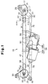
- Fig. 1 is a plan view showing a wiper device of an embodiment according to the present invention, as a whole;
- Fig. 2 is a front view showing the wiper device of Fig. 1;
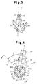
- Fig. 3 is a side view showing a pair of pivot shafts of the wiper device of Fig. 1;
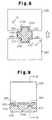
- Fig. 4 is a cross-sectional view taken along line 4-4 of Fig.1 and showing a portion at which a pivot holder is connected to a pipe frame;
- Fig. 5 is a cross-sectional view taken along line 5-5 of Fig. 4;
- Fig. 6 is a cross-sectional view showing the pivot holder being formed using a pair of molds;
- Fig. 7 is a cross-sectional view showing the pipe frame being secured to the pivot holder through caulking with a pair of press dies;
- Fig. 8 is a cross-sectional view taken along line 8-8 of Fig. 9 and showing a pipe frame being secured to a pivot holder through caulking in a prior art device; and
- Fig. 9 is a cross-sectional view taken along line 9-9 of Fig. 8.
-
- An embodiment of the present invention will now be described with reference to Figs. 1 to 7. As shown in Figs. 1 and 2, a
wiper device 10 includes a pair ofpivot holders metal pipe frame 42. Thepipe frame 42 connects thepivot holders pivot holders pivot holders pivot holders attachment hole wiper device 10 to a vehicle body. - The
right pivot holder 12 integrally includes asupport cylinder 16 that has ashaft hole 17. Similarly, theleft pivot holder 14 integrally includes asupport cylinder 18 that has ashaft hole 19. Right and leftpivot shafts support cylinders pivot shaft shaft hole shaft hole 17 or theright pivot shaft 20, and the axis J corresponds to the axis of theshaft hole 19 or theleft pivot shaft 22. - A pair of wiper arms (not shown) are respectively secured to the upper ends of the
pivot shafts support cylinders right pivot lever 24 is secured to the lower end of theright pivot shaft 20, which projects from thesupport cylinder 16. Likewise, aleft pivot lever 26 is secured to the lower end of theleft pivot shaft 22, which projects from thesupport cylinder 18. - The
pivot holders shafts 32, 34 that project from axial intermediate portions of the associatedsupport cylinders shaft 32, 34 is a solid shaft that has a circular cross-sectional shape. The distal end of the connectingshaft 32 forms afitting portion 36 fitted in one axial end of thepipe frame 42, and the distal end of the connecting shaft 34 forms afitting portion 38 fitted in the other axial end of thepipe frame 42. Thepipe frame 42 and the connectingshafts 32, 34 are coaxial. - As shown in Figs. 1 to 5, a pair of recess groups, each of which includes four
recesses 40, are formed in the outer sides of thefitting portions recesses 40 of one group are spaced from therecesses 40 of the other at predetermined intervals in an axial direction of eachfitting portion recesses 40 of each group are spaced from one another at predetermined angular intervals. - The axial opposite ends of the
pipe frame 42form receiving portions fitting portions fitting portion portion portions portion recess 40, thus ensuring that the deformed portion enters therecess 40. Each deformed portion of the receivingportions inward projection 50. Engagement between theprojections 50 and the associated recesses 40 joins eachpivot holder - As shown in Fig. 4 and 5, each
recess 40 has a substantially conical shape. A bottom 4c of eachrecess 40 forms a curved surface, or, preferably, a portion of a spherical surface. Further, the entire wall of eachrecess 40 may form a portion of a spherical surface. Anopening end 40a of eachrecess 40 is curved. It is preferred that the openingend 40a of eachrecess 40 has an arched cross-sectional shape. Each openingend 40a is smoothly connected to a corresponding portion of the'outer sides of thefitting portions - In this embodiment, the
recesses 40 are shaped and located to satisfy the following conditions. More specifically, regarding eachpivot holder maximum depth portion 40b of eachrecess 40 is defined as a normal line X. The angle between the normal line X and a tangential line that corresponds to the openingend 40a of thecorresponding recess 40 is defined as an open angle. Further, the angle between the normal line X and the axis Y, J of thecorresponding pivot shaft Each'recess 40 is shaped and located such that the open angle is constantly greater than zero and equal to or greater than the shaft angle, as viewed along any cross-sectional plane that includes the normal line X. - Figs. 4 and 5 show two of the numerous views of a
certain recess 40 taken along cross-sectional planes that include the normal line X. Fig. 4 is a cross-sectional view showing the portion at which the connectingshaft 32 of theright pivot holder 12 is connected to thepipe frame 42, as taken along the plane that is perpendicular to the axis Z of the connectingshaft 32 and corresponds to themaximum depth portion 40b of therecess 40. As viewed in Fig. 4, or as theright pivot holder 12 is viewed along the axis Z of the connectingshaft 32, the angle between the normal line X, which corresponds to themaximum depth portion 40b of therecess 40, and the tangential line S, which corresponds to the openingend 40a of therecess 40, is defined as a first open angle F. Further, the angle between the axis Y of the right pivot shaft 20 (the shaft hole 17) and the normal line X is defined as a first shaft angle E. Eachrecess 40 is shaped and located to satisfy the following conditions: F > 0 and F ≥ E. The normal line X and the tangential line S of Fig. 4 are located on a plane perpendicular to the axis Z. - Fig. 5 is a cross-sectional view showing the portion at which the connecting
shaft 32 of theright pivot holder 12 is connected to thepipe frame 42, as taken along a plane that includes the axis Z of the connectingshaft 32 and corresponds to themaximum depth portion 40b of therecess 40. As viewed in Fig. 5, or as theright pivot holder 12 is viewed perpendicularly to the axis Z of the connectingshaft 32, the angle between the normal line X, which corresponds to themaximum depth portion 40b of therecess 40, and the tangential line T, which corresponds to the openingend 40a of therecess 40, is defined as a second open angle H. Further, the angle between the axis Y of the right pivot shaft 20 (the shaft hole 17) and the normal line X is defined as a second shaft angle G. Eachrecess 40 is shaped and located to satisfy the following conditions: H > 0 and H ≥ G. The normal line X and the tangential line T of Fig. 5 are located on a plane that includes the axis Z. - In this embodiment, the first open angle F is greater than the first shaft angle E by a predetermined value, as shown in Fig. 4. The second open angle H is greater than the second shaft angle G by a predetermined value, as shown in Fig. 5.
- Although not illustrated, like the open angle of each
recess 40 of theright pivot holder 12, the open angle of eachrecess 40 of theleft pivot holder 14 is constantly greater than zero and equal to or greater than the shaft angle of the left pivot shaft 22 (the shaft hole 19), as viewed along any cross-sectional plane that includes the corresponding normal line X. - As shown in Fig. 3, each
pivot holder pipe frame 42 such that the axis Y of thepivot shaft 20 and the axis J of thepivot shaft 22 form a predetermined angle, as viewed along the axis of thepipe frame 42.
Further, as shown in Fig. 2, the axis Y of thepivot shaft 20 and the axis J of thepivot shaft 22 form a predetermined angle, as viewed perpendicularly to the axis of thepipe frame 42. In other words, the axis Y of thepivot shaft 20 and the axis J of thepivot shaft 22 are non-parallel, as viewed from any direction. - Also, the open angle of each
recess 40 of theright pivot holder 12 is equal to or greater than the shaft angle of theleft pivot shaft 22, as viewed along any cross-sectional plane that includes the normal line X of therecess 40 Likewjse the open angle of eachrecess 40 of theleft pivot holder 14 is equal to or greater than the shaft angle of theright pivot shaft 20, as viewed along any cross-sectional plane that includes the normal line X of therecess 40. In other words, the open angle of eachrecess 40 of one pivot holder is equal to or greater than the shaft angle of the corresponding pivot shaft and the shaft angle of the other pivot shaft, as viewed along any cross-sectional plane that includes the normal line X of therecess 40. - Fig. 6 schematically shows a pair of separate molds M1, M2 for molding the
right pivot holder 12. As shown in the drawing, after molding theright pivot holder 12, the molds M1, M2 are separated from each other along a movement axis parallel with the axis Y of theshaft hole 17. Although not illustrated, theleft pivot holder 14 is also formed with a pair of separate molds, like those of Fig. 6. After molding theleft pivot holder 14, the molds are separated from each other along a movement axis parallel with the axis J of theshaft hole 19. - Fig. 7 schematically shows a pair of press dies 90, 91 for securing the
right pivot holder 12 to thepipe frame 42. As shown in Fig. 7, the press dies 90, 91 respectively have a plurality ofpressing portions recesses 40. When caulking is performed, the press dies 90, 91 are moved toward each other along a predetermined movement axis Y' to press the receivingportion 44 of thepipe frame 42 with thepressing portions left pivot holder 14 is also secured to thepipe frame 42 with a pair of press dies, like those of Fig. 7. When caulking is performed, the press dies are moved toward each other along a predetermined movement axis J'. - As shown in Figs. 1 and 2, a
wiper motor unit 58, which is a drive source, is secured to an axial intermediate portion of thepipe frame 42 through abracket 56. Thewiper motor unit 58 includes amotor 58A and agear unit 58B. Ahousing 60 of thegear unit 58B is secured to thebracket 56. - A
crank arm 72 is secured to the distal end of anoutput shaft 70 that projects from the gear unit 50B. A pair oflink rods crank arm 72 through corresponding ball joints 74. Theright link rod 76 is connected to theright pivot lever 24 through a ball joint 80. Theleft link rod 78 is connected to theleft pivot lever 26 through a ball joint 82. - When the
wiper motor unit 58 operates to rotate thecrank arm 72, thepivot shafts link rods pivot shafts - The above-described
wiper device 10 is a so-called module type wiper device that connects the twopivot holders pivot shafts pipe frame 42. - The illustrated embodiment has the following advantages.
- Each
recess 40 is shaped and located such that the open angle of therecess 40 is constantly greater than zero and equal to or greater than the shaft angle of the corresponding pivot shaft, as viewed along any cross-sectional plane that includes the normal line X of therecess 40. For example, as shown in Fig. 4, eachrecess 40 is shaped and located such that the first open angle F of therecess 40 is greater than zero and equal to or greater than the first shaft angle E, as eachpivot holder shafts 32, 34. Further, as shown in Fig. 5, eachrecess 40 is shaped and located such that the second open angle H of therecess 40 is greater than zero and equal to or greater than the second shaft angle G, as eachpivot holder shafts 32, 34. - As shown in Fig. 6, if the
right pivot holder 12 is formed with the two separate molds M1, M2, the molds M1, M2 are separated from each other along the axis Y of thepivot shaft 20, or theshaft hole 17, after the molding is completed. Likewise, if theleft pivot holder 14 is formed with the two separate molds (not shown), the molds are separated from each other along the axis J of thepivot shaft 22, or theshaft hole 19, after the molding is completed. - In this case, if the aforementioned condition (the open angle must be greater than zero and equal to or greater than the shaft angle) is satisfied, the
recesses 40 do not cause undercut that hampers the separation of the molds. In other words, therecesses 40 may be shaped and located as desired as long as the condition is satisfied. It is simply required that the mold separating direction be parallel with the axis Y, J of eachshaft hole recesses 40. - Accordingly, the two separate molds, which are relatively inexpensive, are readily applied to molding of the
pivot holders pivot holders pivot holder - When the
right pivot holder 12 is secured to thepipe frame 42, as shown in Fig. 7, the press dies 90, 91 are moved toward each other along the predetermine movement axis Y'. Likewise, when theleft pivot holder 14 is secured to thepipe frame 42, the press dies (not shown) are moved toward each other along the predetermine movement axis J'. - The angle between the normal line X of each
recess 40 of one pivot holder and the movement axis of the press dies for the pivot holder is defined as a die movement angle. For example, as shown in Fig. 7, which corresponds to a cross-sectional view of Fig. 4, the angle between the normal line X and the movement axis Y' of the press dies 90, 91 is defined as a die movement angle E'. The movement axis of the press dies 90, 91 is selected to ensure that the die movement angle is constantly equal to or smaller than the open angle of therecess 40, as viewed along any cross-sectional plane that includes the normal line X. In other words, the movement axis of the press dies 90, 91 may be selected as desired, as long as the die movement angle is equal to or smaller than the open angle of therecess 40. - Accordingly, it is unnecessary to increase accuracy for manufacturing the press dies and selecting the die movement direction. That is, even if the press dies have a relatively low accuracy, the
pipe frame 42 is reliably secured to thepivot holders pivot holders - The axis Y of the
pivot shaft 20 and the axis J of thepivot shaft 22 are non-parallel. However, the open angle of eachrecess 40 of one pivot holder is equal to or greater than the shaft angle of the corresponding pivot shaft and the shaft angle of the other pivot shaft, as viewed along any cross-sectional plane that includes the normal line X of therecess 40. Thus, thepivot shafts pipe frame 42 at one time, simply by moving two pairs of press dies for thepivot holders - The bottom 4c of each
recess 40 forms a portion of a spherical surface. Thus, a pressing portion of each press die is also shaped as a non-cornered spherical surface. Accordingly, when caulking is performed, reactive force does not act focally on any portion of thepipe frame 42, thus preventing thepipe frame 42 from being cracked. Further, since the spherical pressing portion does not easily wear, the caulking accuracy and strength of the press dies are maintained for a prolonged time. - The present invention may be embodied as follows.
- The bottom 4c of each
recess 40 does not necessarily have to form a portion of a spherical surface but may be a portion of an oval surface. - In the embodiment of Figs. 1 to 7, the angle between the normal line X and the tangential line that corresponds to the
open end 40a of therecess 40 is defined as the open angle. However, the open angle may be defined differently. For example, the angle between the normal line X and a certain portion of the wall of therecess 40 may be defined as the open angle. Further, eachrecess 40 is shaped and located such that the open angle is constantly greater than zero and equal to or greater than the shaft angle, as viewed along any cross-sectional plane that includes the normal line X. Also in this case, the same operation and advantages as those of the embodiment of Figs. 1 to 7 are obtained. - More specifically, the angle between the normal line X and a certain portion of the wall of the
recess 40 is defined as follows. That is, if a cross section of the wall of therecess 40 forms a straight line, the angle between the straight line and the normal line X is defined as the angle between the normal line X and the certain portion of the wall of therecess 40. Further, if a cross section of the wall of therecess 40 forms a curve, the angle between a tangential line that corresponds to a certain portion of the curve and the normal line X is defined as the angle between the normal line X and the certain portion of the wall of therecess 40. - If each
opening end 40a is curved, a tangential line that corresponds to the openingend 40a is employed, as shown in Fig. 7. However, if the openingend 40a is not curved but is cornered, the tangential line that corresponds to the openingend 40a cannot be employed. If this is the case, it is effective to employ the angle between the normal line X and a certain portion of the wall of therecess 40. - The number of the
recesses 40, which are formed in the correspondingfitting portions pivot holders fitting portion recesses 40.
Claims (10)
- A wiper device comprising:wherein the receiving portions are subjected to caulking with the fitting portions received in the corresponding receiving portions, such that a portion of each receiving portion that corresponds to each recess enters the recess, and the wiper device is characterized in that:a pair of pivot holders, wherein each pivot holder includes a fitting portion that extends along a fitting axis, and a plurality of recesses are formed in an outer side of each fitting portion;a pivot shaft, which is rotationally supported by each pivot holder, wherein a wiper arm is secured to each pivot shaft; anda frame, wherein the frame connects the pivot holders to each other, and a receiving portion in which each fitting portion is received is formed at each end of the frame;each recess includes a curved bottom and a curved open end; andif, regarding each pivot holder, an angle between a normal line that corresponds to a maximum depth portion of each recess and a tangential line that corresponds to the open end of the recess is defined as an open angle while an angle between the axis of the corresponding pivot shaft and the normal line is defined as a shaft angle, the recess is shaped and located such that the open angle is constantly greater than zero and equal to or greater than the shaft angle, as viewed along any cross-sectional plane that includes the normal line.
- A wiper device comprising:wherein the receiving portions are subjected to caulking with the fitting portions received in the corresponding receiving portions, such that a portion of each receiving portion that corresponds to each recess enters the recess, and the wiper device is characterized in that:a pair of pivot holders, wherein each pivot holder includes a fitting portion that extends along a fitting axis, and a plurality of recesses are formed in an outer side of each fitting portion;a pivot shaft, which is rotationally supported by each pivot holder, wherein a wiper arm is secured to each pivot shaft; anda frame, wherein the frame connects the pivot holders to each other, and a receiving portion in which each fitting portion is received is formed at each end of the frame;each recess includes a curved bottom; andif, regarding each pivot holder, an angle between a normal line that corresponds to a maximum depth portion of each recess and a certain portion of a wall that forms the recess is defined as an open angle while an angle between the axis of the corresponding pivot shaft and the normal line is defined as a shaft angle, the recess is shaped and located such that the open angle is constantly greater than zero and equal to or greater than the shaft angle, as viewed along any cross-sectional plane that includes the normal line.
- The wiper device according to claims 1 or 2, characterized in that the bottom of each recess forms a portion of a spherical surface.
- The wiper device according to any one of claims 1 to 3, characterized in that each recess has a substantially conical shape.
- The wiper device according to any one of claims 1 to 4, characterized in that the frame is formed of metal, and each receiving portion plastically deforms such that the portion of the receiving portion that corresponds to each recess forms a projection that enters the recess, when caulking is performed on the receiving portion.
- The wiper device according to any one of claims 1 to 5, characterized in that each fitting portion is a solid shaft that has a circular cross-sectional shape, and each receiving portion has a hollow cylindrical shape for receiving the corresponding fitting portion.
- The wiper device according to any one of claims 1 to 6, characterized in that each pivot holder is formed of aluminum-based metal material through molding.
- The wiper device according to any one of claims 1 to 7, characterized in that the axis of one pivot shaft and the axis of the other are non-parallel with each other.
- The wiper device according to any one of claims 1 to 8, characterized in that the frame is a substantially straight pipe, and the pipe and the fitting portions are coaxial when the pivot holders are secured to the opposite ends of the pipe.
- The wiper device according to any one of claims 1 to 9, characterized in that the open angle of each recess of one pivot holder is equal to or greater than the shaft angle of the corresponding pivot shaft and the shaft angle of the other pivot shaft, as viewed along any cross-sectional plane that includes the normal line of the recess.
Applications Claiming Priority (3)
| Application Number | Priority Date | Filing Date | Title |
|---|---|---|---|
| JP2000118388 | 2000-04-19 | ||
| JP2000118388 | 2000-04-19 | ||
| PCT/JP2001/002993 WO2001079045A1 (en) | 2000-04-19 | 2001-04-06 | Wiper device |
Publications (3)
| Publication Number | Publication Date |
|---|---|
| EP1190920A1 true EP1190920A1 (en) | 2002-03-27 |
| EP1190920A4 EP1190920A4 (en) | 2004-12-01 |
| EP1190920B1 EP1190920B1 (en) | 2006-06-14 |
Family
ID=18629538
Family Applications (1)
| Application Number | Title | Priority Date | Filing Date |
|---|---|---|---|
| EP01917847A Expired - Lifetime EP1190920B1 (en) | 2000-04-19 | 2001-04-06 | Wiper device |
Country Status (7)
| Country | Link |
|---|---|
| US (1) | US6718593B2 (en) |
| EP (1) | EP1190920B1 (en) |
| JP (1) | JP4481548B2 (en) |
| KR (1) | KR100472708B1 (en) |
| CN (1) | CN1182993C (en) |
| DE (1) | DE60120581T2 (en) |
| WO (1) | WO2001079045A1 (en) |
Cited By (2)
| Publication number | Priority date | Publication date | Assignee | Title |
|---|---|---|---|---|
| WO2011047905A1 (en) * | 2009-10-21 | 2011-04-28 | Robert Bosch Gmbh | Windscreen wiper apparatus |
| EP2435280B1 (en) * | 2009-05-08 | 2016-05-11 | Robert Bosch GmbH | Windscreen wiper rod system, method for the production thereof and windscreen wiper device |
Families Citing this family (22)
| Publication number | Priority date | Publication date | Assignee | Title |
|---|---|---|---|---|
| US20030086756A1 (en) * | 2001-11-07 | 2003-05-08 | Trotter Jason K | Modular linkage system |
| US20040253049A1 (en) * | 2003-06-10 | 2004-12-16 | Bissonnette Lee A. | Tubular link with integral crimp socket joint and optional secondary side crimp |
| US7581887B2 (en) * | 2003-11-06 | 2009-09-01 | Robert Bosch Gmbh | Wiper bearing |
| US7861364B2 (en) | 2005-03-21 | 2011-01-04 | Albany Magneto Equipment, Inc. | Ball and socket joint utilizing a single ball, for driving more than one driven member |
| US7716779B2 (en) * | 2005-05-31 | 2010-05-18 | Albany Magneto Equipment, Inc. | Windshield wiper drive alignment |
| US7739771B2 (en) * | 2006-05-24 | 2010-06-22 | Albany Magneto Equipment, Inc. | Windshield wiper drive assembly with dual sector gear drive |
| KR100767445B1 (en) * | 2006-10-18 | 2007-10-17 | 동양기전 주식회사 | Apparatus for driving wiper |
| KR100839998B1 (en) * | 2006-11-02 | 2008-06-19 | 동양기전 주식회사 | Motor apparatus for window wiper of vehicle |
| JP5122849B2 (en) * | 2007-03-28 | 2013-01-16 | 株式会社ミツバ | Wiper device |
| DE102008001828A1 (en) * | 2007-05-18 | 2008-12-18 | Asmo Co., Ltd., Kosai-shi | Motor device and wiper device |
| US8234746B2 (en) * | 2008-09-22 | 2012-08-07 | Robert Bosch Gmbh | Water blocker for wiper system |
| JP2010137683A (en) * | 2008-12-11 | 2010-06-24 | Asmo Co Ltd | Wiper device |
| US8281452B2 (en) * | 2008-12-11 | 2012-10-09 | Asmo Co., Ltd. | Wiper device |
| JP2010137685A (en) * | 2008-12-11 | 2010-06-24 | Asmo Co Ltd | Wiper device |
| JP5172635B2 (en) * | 2008-12-11 | 2013-03-27 | アスモ株式会社 | Wiper device |
| DE102009046153A1 (en) * | 2009-10-29 | 2011-05-12 | Robert Bosch Gmbh | Windscreen wiper device in a vehicle |
| DE102010001968A1 (en) * | 2010-02-16 | 2011-08-18 | Robert Bosch GmbH, 70469 | wiper linkage |
| JP4989742B2 (en) * | 2010-03-04 | 2012-08-01 | アスモ株式会社 | Wiper device |
| WO2012157646A1 (en) * | 2011-05-19 | 2012-11-22 | アスモ 株式会社 | Wiper device, method for manufacturing wiper device, and device for manufacturing wiper device |
| JP5351324B2 (en) * | 2012-10-29 | 2013-11-27 | アスモ株式会社 | Wiper device |
| JP5937489B2 (en) * | 2012-11-05 | 2016-06-22 | アスモ株式会社 | Wiper device manufacturing method and wiper device manufacturing apparatus |
| KR101448723B1 (en) * | 2014-04-14 | 2014-10-13 | 동양기전 주식회사 | Apparatus for assembling vehicle wiper motor unit improved assembility |
Citations (4)
| Publication number | Priority date | Publication date | Assignee | Title |
|---|---|---|---|---|
| US5261286A (en) * | 1991-07-30 | 1993-11-16 | Mitsuba Electric Mfg. Co., Ltd. | Modular-type wiper device |
| DE19540869A1 (en) * | 1994-12-08 | 1996-06-13 | Mitsuba Electric Mfg Co | Method of attaching hollow rod of modular built windscreen wiper |
| WO1999014086A1 (en) * | 1997-09-12 | 1999-03-25 | Itt Manufacturing Enterprises, Inc. | Shaped part with a spigot |
| WO1999020498A1 (en) * | 1997-10-16 | 1999-04-29 | Robert Bosch Gmbh | Driving device for a windshield wiper, especially for vehicle window panes |
Family Cites Families (9)
| Publication number | Priority date | Publication date | Assignee | Title |
|---|---|---|---|---|
| DE2920899A1 (en) | 1979-05-23 | 1981-01-22 | Rau Swf Autozubehoer | Coupling for windscreen wiper - has crimped fitting using tubular sections |
| DE3904045C1 (en) | 1989-02-10 | 1990-04-12 | W. Kordes' Soehne Rosenschulen Gmbh & Co Kg, 2206 Klein Offenseth-Sparrieshoop, De | |
| DE3903976C2 (en) * | 1989-02-10 | 1997-07-03 | Teves Gmbh Alfred | Wiper system |
| DE4023045A1 (en) * | 1990-07-09 | 1992-01-16 | Swf Auto Electric Gmbh | WIPER SYSTEM FOR MOTOR VEHICLES |
| US5536100A (en) * | 1992-12-29 | 1996-07-16 | Ran Enterprises, Inc. | Mechanically joined tubular connection and process to form same |
| DE4328651A1 (en) * | 1993-08-26 | 1995-03-02 | Teves Gmbh Alfred | Fasteners for a windshield wiper system |
| JP3215671B2 (en) * | 1998-07-24 | 2001-10-09 | アスモ株式会社 | Wiper device and method for manufacturing hollow frame of wiper device |
| JP2000052938A (en) * | 1998-08-05 | 2000-02-22 | Asmo Co Ltd | Wiper device |
| JP3859395B2 (en) * | 1999-06-02 | 2006-12-20 | 自動車電機工業株式会社 | Wiper unit |
-
2001
- 2001-04-06 KR KR10-2001-7015952A patent/KR100472708B1/en active IP Right Grant
- 2001-04-06 JP JP2001576320A patent/JP4481548B2/en not_active Expired - Lifetime
- 2001-04-06 DE DE60120581T patent/DE60120581T2/en not_active Expired - Lifetime
- 2001-04-06 WO PCT/JP2001/002993 patent/WO2001079045A1/en active IP Right Grant
- 2001-04-06 US US10/019,206 patent/US6718593B2/en not_active Expired - Lifetime
- 2001-04-06 CN CNB018009735A patent/CN1182993C/en not_active Expired - Lifetime
- 2001-04-06 EP EP01917847A patent/EP1190920B1/en not_active Expired - Lifetime
Patent Citations (4)
| Publication number | Priority date | Publication date | Assignee | Title |
|---|---|---|---|---|
| US5261286A (en) * | 1991-07-30 | 1993-11-16 | Mitsuba Electric Mfg. Co., Ltd. | Modular-type wiper device |
| DE19540869A1 (en) * | 1994-12-08 | 1996-06-13 | Mitsuba Electric Mfg Co | Method of attaching hollow rod of modular built windscreen wiper |
| WO1999014086A1 (en) * | 1997-09-12 | 1999-03-25 | Itt Manufacturing Enterprises, Inc. | Shaped part with a spigot |
| WO1999020498A1 (en) * | 1997-10-16 | 1999-04-29 | Robert Bosch Gmbh | Driving device for a windshield wiper, especially for vehicle window panes |
Non-Patent Citations (1)
| Title |
|---|
| See also references of WO0179045A1 * |
Cited By (2)
| Publication number | Priority date | Publication date | Assignee | Title |
|---|---|---|---|---|
| EP2435280B1 (en) * | 2009-05-08 | 2016-05-11 | Robert Bosch GmbH | Windscreen wiper rod system, method for the production thereof and windscreen wiper device |
| WO2011047905A1 (en) * | 2009-10-21 | 2011-04-28 | Robert Bosch Gmbh | Windscreen wiper apparatus |
Also Published As
| Publication number | Publication date |
|---|---|
| US20020162184A1 (en) | 2002-11-07 |
| EP1190920A4 (en) | 2004-12-01 |
| EP1190920B1 (en) | 2006-06-14 |
| DE60120581T2 (en) | 2007-01-25 |
| KR100472708B1 (en) | 2005-03-08 |
| KR20020029334A (en) | 2002-04-18 |
| CN1182993C (en) | 2005-01-05 |
| DE60120581D1 (en) | 2006-07-27 |
| JP4481548B2 (en) | 2010-06-16 |
| WO2001079045A1 (en) | 2001-10-25 |
| US6718593B2 (en) | 2004-04-13 |
| CN1366501A (en) | 2002-08-28 |
Similar Documents
| Publication | Publication Date | Title |
|---|---|---|
| EP1190920B1 (en) | Wiper device | |
| US6148581A (en) | Internal high pressure formed nodal connection element for a frame construction, and method of making same | |
| JPH07259840A (en) | Ball shaft of ball joint for automobile | |
| US6044543A (en) | Method of manufacturing a joint housing | |
| KR100616757B1 (en) | Windscreen wiper system | |
| KR20190090381A (en) | The connection between the aluminum side rail of the vehicle and the control arm | |
| KR100616268B1 (en) | wiper support | |
| WO2011108393A1 (en) | Wiper device | |
| CZ296754B6 (en) | Windscreen wiper | |
| KR20140021502A (en) | Wiper device, method for manufacturing wiper device, and device for manufacturing wiper device | |
| EP1293692B2 (en) | Joint boot made of resin | |
| KR100712869B1 (en) | Wiper system | |
| JP2002521258A (en) | Fixing mechanism for tubular blanks | |
| JP3433772B2 (en) | Bottom structure of vehicle shock absorber and method of forming the same | |
| JP3982534B2 (en) | Removable cardan joint yoke for automobile steering column | |
| US6536070B1 (en) | Windscreen wiper system | |
| US20090211396A1 (en) | Differential housing and production method | |
| JP2004516942A (en) | How to make a ball joint casing | |
| US20050035091A1 (en) | Process for manufacturing a tie rod housing | |
| CN102149929B (en) | Connect bolt, toolroom machine and the manufacture method for connecting bolt | |
| US8029373B2 (en) | Fixed constant velocity universal joint | |
| EP1085227A1 (en) | Special reinforcement system for lining bearings in cardan joints | |
| GB2370338A (en) | A resilient bush for connecting parts of vehicle frames and sub-frames | |
| US7001076B2 (en) | Housing for receiving a bearing component and process for manufacturing same | |
| CN110225837A (en) | Universal-joint fork and actuator with universal-joint fork |
Legal Events
| Date | Code | Title | Description |
|---|---|---|---|
| PUAI | Public reference made under article 153(3) epc to a published international application that has entered the european phase |
Free format text: ORIGINAL CODE: 0009012 |
|
| 17P | Request for examination filed |
Effective date: 20011218 |
|
| AK | Designated contracting states |
Kind code of ref document: A1 Designated state(s): AT BE CH CY DE DK ES FI FR GB GR IE IT LI LU MC NL PT SE TR |
|
| RBV | Designated contracting states (corrected) |
Designated state(s): DE FR IT |
|
| A4 | Supplementary search report drawn up and despatched |
Effective date: 20041020 |
|
| RIC1 | Information provided on ipc code assigned before grant |
Ipc: 7B 60S 1/04 A |
|
| 17Q | First examination report despatched |
Effective date: 20050330 |
|
| GRAP | Despatch of communication of intention to grant a patent |
Free format text: ORIGINAL CODE: EPIDOSNIGR1 |
|
| GRAS | Grant fee paid |
Free format text: ORIGINAL CODE: EPIDOSNIGR3 |
|
| GRAA | (expected) grant |
Free format text: ORIGINAL CODE: 0009210 |
|
| AK | Designated contracting states |
Kind code of ref document: B1 Designated state(s): DE FR IT |
|
| PG25 | Lapsed in a contracting state [announced via postgrant information from national office to epo] |
Ref country code: IT Free format text: LAPSE BECAUSE OF FAILURE TO SUBMIT A TRANSLATION OF THE DESCRIPTION OR TO PAY THE FEE WITHIN THE PRESCRIBED TIME-LIMIT;WARNING: LAPSES OF ITALIAN PATENTS WITH EFFECTIVE DATE BEFORE 2007 MAY HAVE OCCURRED AT ANY TIME BEFORE 2007. THE CORRECT EFFECTIVE DATE MAY BE DIFFERENT FROM THE ONE RECORDED. Effective date: 20060614 |
|
| REF | Corresponds to: |
Ref document number: 60120581 Country of ref document: DE Date of ref document: 20060727 Kind code of ref document: P |
|
| ET | Fr: translation filed | ||
| PLBE | No opposition filed within time limit |
Free format text: ORIGINAL CODE: 0009261 |
|
| STAA | Information on the status of an ep patent application or granted ep patent |
Free format text: STATUS: NO OPPOSITION FILED WITHIN TIME LIMIT |
|
| 26N | No opposition filed |
Effective date: 20070315 |
|
| REG | Reference to a national code |
Ref country code: FR Ref legal event code: PLFP Year of fee payment: 16 |
|
| REG | Reference to a national code |
Ref country code: FR Ref legal event code: PLFP Year of fee payment: 17 |
|
| REG | Reference to a national code |
Ref country code: FR Ref legal event code: PLFP Year of fee payment: 18 |
|
| REG | Reference to a national code |
Ref country code: DE Ref legal event code: R082 Ref document number: 60120581 Country of ref document: DE Representative=s name: ISARPATENT - PATENTANWAELTE- UND RECHTSANWAELT, DE Ref country code: DE Ref legal event code: R081 Ref document number: 60120581 Country of ref document: DE Owner name: DENSO CORPORATION, KARIYA-CITY, JP Free format text: FORMER OWNER: ASMO CO., LTD., KOSAI-SHI, SHIZUOKA-KEN, JP Ref country code: DE Ref legal event code: R082 Ref document number: 60120581 Country of ref document: DE Representative=s name: ISARPATENT - PATENT- UND RECHTSANWAELTE BEHNIS, DE Ref country code: DE Ref legal event code: R082 Ref document number: 60120581 Country of ref document: DE Representative=s name: ISARPATENT - PATENT- UND RECHTSANWAELTE BARTH , DE |
|
| PGFP | Annual fee paid to national office [announced via postgrant information from national office to epo] |
Ref country code: FR Payment date: 20200420 Year of fee payment: 20 Ref country code: DE Payment date: 20200420 Year of fee payment: 20 |
|
| PGFP | Annual fee paid to national office [announced via postgrant information from national office to epo] |
Ref country code: IT Payment date: 20200428 Year of fee payment: 20 |
|
| REG | Reference to a national code |
Ref country code: DE Ref legal event code: R071 Ref document number: 60120581 Country of ref document: DE |