EP1190734A1 - Mixing/charging port for medical treatment - Google Patents
Mixing/charging port for medical treatment Download PDFInfo
- Publication number
- EP1190734A1 EP1190734A1 EP01122482A EP01122482A EP1190734A1 EP 1190734 A1 EP1190734 A1 EP 1190734A1 EP 01122482 A EP01122482 A EP 01122482A EP 01122482 A EP01122482 A EP 01122482A EP 1190734 A1 EP1190734 A1 EP 1190734A1
- Authority
- EP
- European Patent Office
- Prior art keywords
- mixing
- charging port
- valve
- seating
- passage
- Prior art date
- Legal status (The legal status is an assumption and is not a legal conclusion. Google has not performed a legal analysis and makes no representation as to the accuracy of the status listed.)
- Granted
Links
- 238000002156 mixing Methods 0.000 title claims abstract description 73
- 238000003780 insertion Methods 0.000 claims abstract description 25
- 230000037431 insertion Effects 0.000 claims abstract description 25
- 238000004873 anchoring Methods 0.000 claims abstract description 4
- 230000000452 restraining effect Effects 0.000 claims abstract description 4
- 230000037452 priming Effects 0.000 abstract description 16
- 239000003814 drug Substances 0.000 abstract description 8
- 229940079593 drug Drugs 0.000 abstract description 8
- 230000000717 retained effect Effects 0.000 abstract description 7
- 239000008280 blood Substances 0.000 abstract description 5
- 210000004369 blood Anatomy 0.000 abstract description 5
- 239000000243 solution Substances 0.000 description 10
- 239000007788 liquid Substances 0.000 description 9
- 238000001802 infusion Methods 0.000 description 2
- 238000002347 injection Methods 0.000 description 2
- 239000007924 injection Substances 0.000 description 2
- 239000000463 material Substances 0.000 description 2
- 230000015572 biosynthetic process Effects 0.000 description 1
- 230000000694 effects Effects 0.000 description 1
- 230000014759 maintenance of location Effects 0.000 description 1
- 238000004519 manufacturing process Methods 0.000 description 1
- 238000000034 method Methods 0.000 description 1
- 230000002265 prevention Effects 0.000 description 1
- 238000010074 rubber mixing Methods 0.000 description 1
Images



Classifications
-
- A—HUMAN NECESSITIES
- A61—MEDICAL OR VETERINARY SCIENCE; HYGIENE
- A61M—DEVICES FOR INTRODUCING MEDIA INTO, OR ONTO, THE BODY; DEVICES FOR TRANSDUCING BODY MEDIA OR FOR TAKING MEDIA FROM THE BODY; DEVICES FOR PRODUCING OR ENDING SLEEP OR STUPOR
- A61M39/00—Tubes, tube connectors, tube couplings, valves, access sites or the like, specially adapted for medical use
- A61M39/02—Access sites
- A61M39/04—Access sites having pierceable self-sealing members
- A61M39/045—Access sites having pierceable self-sealing members pre-slit to be pierced by blunt instrument
-
- Y—GENERAL TAGGING OF NEW TECHNOLOGICAL DEVELOPMENTS; GENERAL TAGGING OF CROSS-SECTIONAL TECHNOLOGIES SPANNING OVER SEVERAL SECTIONS OF THE IPC; TECHNICAL SUBJECTS COVERED BY FORMER USPC CROSS-REFERENCE ART COLLECTIONS [XRACs] AND DIGESTS
- Y10—TECHNICAL SUBJECTS COVERED BY FORMER USPC
- Y10S—TECHNICAL SUBJECTS COVERED BY FORMER USPC CROSS-REFERENCE ART COLLECTIONS [XRACs] AND DIGESTS
- Y10S604/00—Surgery
- Y10S604/905—Aseptic connectors or couplings, e.g. frangible, piercable
Definitions
- the present invention relates to a mixing/charging port for medical treatment, which is placed on a medical instrument to make it easy and reliable to mix/charge solutions from the outside of a feeding passage or, on the other hand, to collect solutions from the inside of the feeding passage.
- a main feeding passage with a side-infusing line in order to mix/charge different kinds of drug solutions or to collect the liquid flowing in the feeding passage as a sample.
- a feeding passage of an infusion set provided with a rubber mixing/charging port (cock) for piercing by needles is used and solutions are mixed/charged by piercing the mixing/charging port with an injection needle, etc.
- the mixing/charging port capable of holding an insertion member has been considered.
- An example includes a mixing/charging port equipped with a valve that opens when a male luer located at the tip of a syringe is inserted into the mixing/charging port to push the valve and which closes by itself when the luer is pulled out from the mixing/charging port.
- the amount of drug solution to be mixed/charged is small, the administration of an effective amount of drug solution may not be carried out.
- the structure of the valve becomes complicated, which may lead to increasing cost.
- failures are more likely to occur, and the valve is more likely to be broken.
- the conventional simple-structured mixing/charging port for example, a mixing/charging port merely equipped with a disk-like valve made of an elastic member having a slit
- the conventional disk-like valve is formed of a material having a large elasticity and has a simple structure in which the thick main body is merely provided with a slit, so that the valve is exhibits a large resistance when the luer is inserted into the valve, and the valve is deformed largely when the valve holds the luer.
- the thickness of the elastic member is reduced or a material having a small elasticity is used in order to reduce the resistance when the luer is inserted, the backflow prevention effect of the valve is lowered, which may cause liquid leaking.
- a mixing/charging port for medical treatment having a simple structure and capable of reliably holding an insertion member, which includes a disk-like valve having an insertion hole at the center, a seating for supporting the lower part of the periphery of the valve with the center of the rear surface side of the valve left unsupported, a cover for restraining the valve by covering at least the upper part of the periphery of the valve with the center on the front surface side of the valve left uncovered, and an anchor means for anchoring the insertion member to the mixing/charging port by inserting the insertion member into the insertion hole and by using the edge portion of the cover provided with a fitting hole.
- reference numeral 1 denotes a disk-like valve
- 2 denotes a cover
- 3 denotes an insertion hole
- reference numeral 5 denotes an annular rib
- 6 denotes a fitting hole
- 7 denotes a seating
- 8 denotes a passage
- 9 denotes a hook.
- the valve 1 is sandwiched between the hook 9 of the cover 2 and the annular rib 5.
- region A indicates a cavity of the bottom surface of the mixing/charging port proper
- region B indicates a difference in level between the bottom surface and the opening part of the main route.
- Figure 3 is a longitudinal sectional view showing the mixing/charging port during the priming.
- the regions A and B are the same as those shown in Figure 2, and the region C is a connection part between the mixing/charging port proper and a small-diameter tube 10.
- Figure 3 is a drawing inverted to show the mixing-charging port upside down.
- a mixing/charging port for medical treatment of the present invention includes a disk-like valve having an insertion hole at the center, a seating for supporting the lower part of the periphery of the valve with the center of the rear surface side of the valve left unsupported, and a cover for restraining the valve by covering at least the upper part of the periphery of the valve with the center of the front surface side of the valve left uncovered, wherein a fitting hole defined by an inner edge portion of the cover works as an anchor for anchoring an insertion member to the mixing/charging port in a way in which the insertion member is fitted to the fitting hole when the insertion member is inserted into the insertion hole; and the bottom surface of an opening part of a passage is located at a lower level relative to the inner bottom surface of the seating.
- the passage is circular in cross section and the inner bottom surface of the seating is provided with a concave part having a shape in cross section that is the same as a shape defined by a chord and an arc located in a lower part of the opening part of the passage. It is preferable because the resident air bubbles are removed easily and also the passage for infusing liquid can be secured when the insertion member is inserted into the valve.
- the inner bottom surface of the seating is provided with a curved part of the bottom continuously connecting the inner side surface to the inner bottom surface of the seating. It is preferable because it is possible to allow the flow during the priming to be smoother and to suppress the occurrence of the turbulent flow more efficiently.
- any one side of the opening parts of the passage of the mixing/charging port is connected to a tube with a diameter smaller than the diameter of the opening part of the passage via a joint having a funnel shape in which the inner diameter gradually is reduced. It is preferable because it is possible to avoid the generation of turbulent flow due to the difference in diameter in the vicinity of the outlet of priming, thus to prevent air bubbles from occurring in the vicinity of the outlet of flow.
- Figure 1A is a longitudinal sectional view of a conventional mixing/charging port
- Figure 1B is a cross sectional view of the mixing/charging port along line I-I in Figure 1A
- Figure 1C is a conventional plan view of the mixing/charging port.
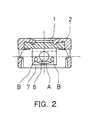
- Figure 2 is a cross-sectional view showing a conventional mixing/charging port for medical treatment.
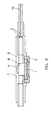
- Figure 3 is a longitudinal sectional view showing a conventional mixing/charging port for medical treatment.
- Figure 4 is a cross-sectional view showing a mixing/charging port for medical treatment of an embodiment according to the present invention.
- Figure 5 is a longitudinal sectional view showing a mixing/charging port for medical treatment of an embodiment according to the present invention.
- Figure 4 is a cross-sectional view showing a configuration of a mixing/charging port for medical treatment of this embodiment of the present invention.
- reference numeral 5 denotes an annular rib
- 7 denotes a seating
- 8 denotes a passage
- 9 denotes a hook.
- the mixing/charging port for medical treatment of Figure 4 is the same as in Figure 1 in that the valve 1 is sandwiched between the hook 9 of the cover 2 and the annular rib 5.
- the mixing/charging port for medical treatment of Figure 4 is different from that of Figure 1 in the location relationship between the passage 8 and the seating 7. More specifically, in the conventional mixing/charging port of Figure 1, the bottom surface of the passage 8 is located at a level above the inner bottom surface of the seating 7, whereas in Figure 4, the bottom surface of the passage 8 is located at a level below the inner bottom surface of the seating 7. Furthermore, in Figure 4, the cavity of the inner bottom surface of the seating 7 is allowed to correspond to the shape of the bottom surface of the passage 8.
- the inner bottom surface of the seating 7 is provided with a groove having a shape obtained by cutting off the inner bottom surface of the seating 7 with the shape of the passage 8, in which the cross section of the groove has a shape surrounded by a chord and an arc that are located in a lower part of the cross section of the passage 8. Therefore, no difference in level occurs between the opening part of the passage 8 and the inner bottom surface of the seating 7. Therefore, it is possible to prevent air bubbles from being generated by the occurrence of turbulent flow when flow collides with the position of a difference in level. In addition, it is possible to secure the passage for infusing liquid when the insertion member is inserted into the mixing/charging port.
- the inner bottom surface of the seating 7 is provided with a groove formed by uniformly cutting out the inner bottom surface of the seating 7 with the shape of the passage 8.
- the bottom of the groove corresponds to the bottom surface of the seating 7 at the center of the mixing/charging port and is cut out gradually deeper toward the both sides of the opening portion of the passage.
- the inner side surface and the bottom surface may be connected continuously with a generally curved surface so as not to form a sharp corner on the inner bottom surface of the seating 7.
- Figure 5 is a cross sectional view showing a mixing/charging port for medical treatment of this embodiment according to the present invention. Since priming is carried out with the mixing/charging port turned upside down, Figure 5 is a drawing inverted to show the mixing-charging port upside down.
- the bottom surface (the upper part in Figure 5) of the passage 8 is located at a lower level relative to the inner bottom surface (the upper part in Figure 5) of the seating 7, and no difference in level occurs between the main route of flow and the opening part of the passage 8. Moreover, in the upper surface (the lower part in Figure 5) of the passage 8, a difference in level occurs between the main route of flow and the opening part of the passage 8.
- liquid is filled in a state in which the mixing/charging port is turned upside down, air bubbles generated herein easily can be ejected to the outside by the priming.
- a joint 11 having a funnel shape with a gradually reducing diameter may be provided.
- liquid is allowed to flow smoothly and the occurrence of turbulent flow caused by the collision of flow is less likely to occur.
- the joint 11 is provided at the outlet side of the priming. It is preferable because air bubbles tend to occur when a difference in level is present at the outlet side, and the air bubble contaminated into the mixing/charging port proper can be ejected to the outside more smoothly.
Landscapes
- Health & Medical Sciences (AREA)
- Heart & Thoracic Surgery (AREA)
- Pulmonology (AREA)
- Engineering & Computer Science (AREA)
- Anesthesiology (AREA)
- Biomedical Technology (AREA)
- Hematology (AREA)
- Life Sciences & Earth Sciences (AREA)
- Animal Behavior & Ethology (AREA)
- General Health & Medical Sciences (AREA)
- Public Health (AREA)
- Veterinary Medicine (AREA)
- Infusion, Injection, And Reservoir Apparatuses (AREA)
- External Artificial Organs (AREA)
Abstract
Description
- The present invention relates to a mixing/charging port for medical treatment, which is placed on a medical instrument to make it easy and reliable to mix/charge solutions from the outside of a feeding passage or, on the other hand, to collect solutions from the inside of the feeding passage.
- In infusing a drug solution or transfusing blood into a patient, it is often necessary to provide a main feeding passage with a side-infusing line in order to mix/charge different kinds of drug solutions or to collect the liquid flowing in the feeding passage as a sample. Conventionally, in this case, a feeding passage of an infusion set provided with a rubber mixing/charging port (cock) for piercing by needles is used and solutions are mixed/charged by piercing the mixing/charging port with an injection needle, etc.
- However, in such a method, when piercing the site other than the predetermined piercing site of the mixing/charging port with the needle, the liquid may leak from the site. Another problem is that the injection needle may be contaminated due to a working error, etc. In order to fix and hold a luer, etc. to be inserted ("an insertion member" will be referred to hereinafter), recently, the mixing/charging port capable of holding an insertion member has been considered. An example includes a mixing/charging port equipped with a valve that opens when a male luer located at the tip of a syringe is inserted into the mixing/charging port to push the valve and which closes by itself when the luer is pulled out from the mixing/charging port.
- However, in such a mixing/charging port, it is necessary to hold a luer at the mixing/charging port regardless of the state in which the valve is inserted (i.e., valve opens) or the state in which the valve is pulled out (i.e., valve closes). Therefore, there are the following various problems. More specifically, first, it is necessary to deepen a luer receiving part of the mixing/charging port. With such a shape, it is difficult to remove the liquid leaking from the valve, which easily may become unsanitary. Furthermore, in the mixing/charging port having such a deep luer receiving part, the liquid may begin to be mixed/charged in a state in which the luer is not sufficiently inserted into the valve. In this case, if the amount of drug solution to be mixed/charged is small, the administration of an effective amount of drug solution may not be carried out. Secondly, the structure of the valve becomes complicated, which may lead to increasing cost. Furthermore, as the structure of the valve is more complicated, failures are more likely to occur, and the valve is more likely to be broken.
- On the other hand, in the conventional simple-structured mixing/charging port (for example, a mixing/charging port merely equipped with a disk-like valve made of an elastic member having a slit), it was difficult to insert a luer of a syringe into the mixing/charging port. If possible, it was difficult to hold the syringe reliably at the mixing/charging port. This is because the conventional disk-like valve is formed of a material having a large elasticity and has a simple structure in which the thick main body is merely provided with a slit, so that the valve is exhibits a large resistance when the luer is inserted into the valve, and the valve is deformed largely when the valve holds the luer. However, if the thickness of the elastic member is reduced or a material having a small elasticity is used in order to reduce the resistance when the luer is inserted, the backflow prevention effect of the valve is lowered, which may cause liquid leaking.
- In order to solve the above-mentioned problems, there has been a proposal of a mixing/charging port for medical treatment having a simple structure and capable of reliably holding an insertion member, which includes a disk-like valve having an insertion hole at the center, a seating for supporting the lower part of the periphery of the valve with the center of the rear surface side of the valve left unsupported, a cover for restraining the valve by covering at least the upper part of the periphery of the valve with the center on the front surface side of the valve left uncovered, and an anchor means for anchoring the insertion member to the mixing/charging port by inserting the insertion member into the insertion hole and by using the edge portion of the cover provided with a fitting hole.
- Figures 1A, 1B and 1C are projection drawings from three directions of an example of a conventional mixing/charging port for medical treatment. That is, Figure 1A is a longitudinal sectional view of a mixing/charging port; Figure 1B is a cross sectional view of the mixing/charging port along line I-I in Figure 1A; and Figure 1C is a plan view of the mixing/charging port, respectively.
- In Figure 1,
reference numeral 1 denotes a disk-like valve, 2 denotes a cover, and 3 denotes an insertion hole. Furthermore,reference numeral 5 denotes an annular rib, 6 denotes a fitting hole, 7 denotes a seating, 8 denotes a passage, and 9 denotes a hook. In this structure, thevalve 1 is sandwiched between thehook 9 of thecover 2 and theannular rib 5. - However, in the above-mentioned mixing/charging port for medical treatment, there has been a problem in that when priming of the inner part of the mixing/charging port is carried out, air bubbles may be present in some parts such as a cavity of the bottom surface of the mixing/charging port proper, a difference in level between the bottom surface and an opening part of the main route, a connection part between the mixing/charging port proper and a small-diameter tube, or the like. The occurrence of parts in which air bubbles are present makes it impossible to carry out the priming sufficiently, which may lead to a problem in that transfusion of blood or infusion of a drug solution into the vessel of a patient cannot be carried out safely.
- For example, when priming a conventional mixing/charging port for medical treatment, air bubbles tend to be present in regions A and B as shown in Figure 2, which is a cross sectional view of a conventional mixing/charging port for medical treatment. More specifically, the region A indicates a cavity of the bottom surface of the mixing/charging port proper, and the region B indicates a difference in level between the bottom surface and the opening part of the main route.
- Furthermore, since the priming is carried out with the mixing/charging port turned upside down at a pressure of, for example, about 300 mmHg, air bubbles tend to be present in the regions A, B and C as shown in Figure 3, which is a longitudinal sectional view showing the mixing/charging port during the priming. The regions A and B are the same as those shown in Figure 2, and the region C is a connection part between the mixing/charging port proper and a small-
diameter tube 10. Because the priming is carried out with the mixing/charging port turned upside down, Figure 3 is a drawing inverted to show the mixing-charging port upside down. - With the foregoing in mind, it is an object of the present invention to provide a mixing/charging port for medical treatment in which air bubbles are not present even at the time of priming and which is capable of infusing a drug solution or transfusing blood into a patient safely.
- In order to achieve the above-mentioned object, a mixing/charging port for medical treatment of the present invention includes a disk-like valve having an insertion hole at the center, a seating for supporting the lower part of the periphery of the valve with the center of the rear surface side of the valve left unsupported, and a cover for restraining the valve by covering at least the upper part of the periphery of the valve with the center of the front surface side of the valve left uncovered, wherein a fitting hole defined by an inner edge portion of the cover works as an anchor for anchoring an insertion member to the mixing/charging port in a way in which the insertion member is fitted to the fitting hole when the insertion member is inserted into the insertion hole; and the bottom surface of an opening part of a passage is located at a lower level relative to the inner bottom surface of the seating.
- With such a configuration, since a cavity itself is eliminated from the bottom surface of the mixing/charging port main body and no difference in level occurs between a main stream of flow and the opening part of the passage, the flow is not made to be turbulent (i.e., turbulent flow does not occur). Thus, it is possible to prevent air bubbles from occurring. Furthermore, even if air bubbles occur due to a working error, etc., since there is no space for air bubbles to be able to be retained, such air bubbles easily can be ejected from the inside of the mixing/charging port.
- Furthermore, in the mixing/charging port for medical treatment of the present invention, it is preferable that the passage is circular in cross section and the inner bottom surface of the seating is provided with a concave part having a shape in cross section that is the same as a shape defined by a chord and an arc located in a lower part of the opening part of the passage. It is preferable because the resident air bubbles are removed easily and also the passage for infusing liquid can be secured when the insertion member is inserted into the valve.
- Furthermore, in the mixing/charging port for medical treatment of the present invention, it is preferable that the inner bottom surface of the seating is provided with a curved part of the bottom continuously connecting the inner side surface to the inner bottom surface of the seating. It is preferable because it is possible to allow the flow during the priming to be smoother and to suppress the occurrence of the turbulent flow more efficiently.
- Furthermore, in the mixing/charging port for medical treatment of the present invention, it is preferable that any one side of the opening parts of the passage of the mixing/charging port is connected to a tube with a diameter smaller than the diameter of the opening part of the passage via a joint having a funnel shape in which the inner diameter gradually is reduced. It is preferable because it is possible to avoid the generation of turbulent flow due to the difference in diameter in the vicinity of the outlet of priming, thus to prevent air bubbles from occurring in the vicinity of the outlet of flow.
- Figure 1A is a longitudinal sectional view of a conventional mixing/charging port; Figure 1B is a cross sectional view of the mixing/charging port along line I-I in Figure 1A; and Figure 1C is a conventional plan view of the mixing/charging port.
- Figure 2 is a cross-sectional view showing a conventional mixing/charging port for medical treatment.
- Figure 3 is a longitudinal sectional view showing a conventional mixing/charging port for medical treatment.
- Figure 4 is a cross-sectional view showing a mixing/charging port for medical treatment of an embodiment according to the present invention.
- Figure 5 is a longitudinal sectional view showing a mixing/charging port for medical treatment of an embodiment according to the present invention.
- Hereinafter, the mixing/charging port for medical treatment of the present invention will be described by way of embodiments with reference to the accompanying drawings. Figure 4 is a cross-sectional view showing a configuration of a mixing/charging port for medical treatment of this embodiment of the present invention. In Figure 4,
reference numeral 5 denotes an annular rib, 7 denotes a seating, 8 denotes a passage and 9 denotes a hook. The mixing/charging port for medical treatment of Figure 4 is the same as in Figure 1 in that thevalve 1 is sandwiched between thehook 9 of thecover 2 and theannular rib 5. - The mixing/charging port for medical treatment of Figure 4 is different from that of Figure 1 in the location relationship between the
passage 8 and theseating 7. More specifically, in the conventional mixing/charging port of Figure 1, the bottom surface of thepassage 8 is located at a level above the inner bottom surface of theseating 7, whereas in Figure 4, the bottom surface of thepassage 8 is located at a level below the inner bottom surface of theseating 7. Furthermore, in Figure 4, the cavity of the inner bottom surface of theseating 7 is allowed to correspond to the shape of the bottom surface of thepassage 8. - By locating the bottom surface of the
passage 8 at a lower level than the inner bottom surface of theseating 7, a cavity that was present in the bottom surface of the mixing/charging port is eliminated. Thereby, it is possible to prevent the formation of air bubbles, which tend to occur in the cavity. - Furthermore, the inner bottom surface of the
seating 7 is provided with a groove having a shape obtained by cutting off the inner bottom surface of theseating 7 with the shape of thepassage 8, in which the cross section of the groove has a shape surrounded by a chord and an arc that are located in a lower part of the cross section of thepassage 8. Therefore, no difference in level occurs between the opening part of thepassage 8 and the inner bottom surface of theseating 7. Therefore, it is possible to prevent air bubbles from being generated by the occurrence of turbulent flow when flow collides with the position of a difference in level. In addition, it is possible to secure the passage for infusing liquid when the insertion member is inserted into the mixing/charging port. - Furthermore, even if air bubbles are generated due to a working error, etc., if only the priming is carried out with the mixing/charging port turned upside down, there is no space for air bubbles to be able to be retained. Therefore, it is possible to allow such air bubbles to be ejected to the outside of the mixing/charging port easily by the priming.
- From the viewpoint of the manufacturing cost, it is preferable that the inner bottom surface of the
seating 7 is provided with a groove formed by uniformly cutting out the inner bottom surface of theseating 7 with the shape of thepassage 8. However, in order to minimize the amount of the resident air bubbles, it is more preferable that the bottom of the groove corresponds to the bottom surface of theseating 7 at the center of the mixing/charging port and is cut out gradually deeper toward the both sides of the opening portion of the passage. - Furthermore, at the inner bottom surface of the
seating 7, the inner side surface and the bottom surface may be connected continuously with a generally curved surface so as not to form a sharp corner on the inner bottom surface of theseating 7. By providing such a curved part of thebottom 4, it is possible to suppress the occurrence of turbulent flow more efficiently. Furthermore, it is possible to reduce the generation of air bubbles more efficiently as well as to reduce space for air bubbles to be able to be retained. - Figure 5 is a cross sectional view showing a mixing/charging port for medical treatment of this embodiment according to the present invention. Since priming is carried out with the mixing/charging port turned upside down, Figure 5 is a drawing inverted to show the mixing-charging port upside down.
- In Figure 5, the bottom surface (the upper part in Figure 5) of the
passage 8 is located at a lower level relative to the inner bottom surface (the upper part in Figure 5) of theseating 7, and no difference in level occurs between the main route of flow and the opening part of thepassage 8. Moreover, in the upper surface (the lower part in Figure 5) of thepassage 8, a difference in level occurs between the main route of flow and the opening part of thepassage 8. However, since liquid is filled in a state in which the mixing/charging port is turned upside down, air bubbles generated herein easily can be ejected to the outside by the priming. - With such a configuration, since the bottom surface of the
passage 8 is located at a lower level relative to the inner bottom surface of theseating 7, it is possible to prevent air bubbles from being retained in the cavity of the bottom surface of the mixing/charging port proper. Furthermore, since no difference in level occurs between the main route of flow and the opening part of thepassage 8, a smoother flow can be achieved and also the generation of air bubbles due to the occurrence of turbulent flow can be suppressed. - Furthermore, in order to prevent air bubbles from being retained in the connection part between the
passage 8 and a small-diameter tube at the outlet port of the priming, a joint 11 having a funnel shape with a gradually reducing diameter may be provided. By providing such a joint 11, liquid is allowed to flow smoothly and the occurrence of turbulent flow caused by the collision of flow is less likely to occur. Thus, the generation of air bubbles can be prevented and the occurrence and retention of air bubbles can be avoided. - Since no air bubbles are retained, it is possible to avoid the risk in that air bubbles are infused into the patient when transfusing blood or infusing a drug solution is carried out. Therefore, a medical treatment can be carried out safely.
- Moreover, it is more preferable that the joint 11 is provided at the outlet side of the priming. It is preferable because air bubbles tend to occur when a difference in level is present at the outlet side, and the air bubble contaminated into the mixing/charging port proper can be ejected to the outside more smoothly.
Claims (4)
- A mixing/charging port for medical treatment comprisinga disk-like valve having an insertion hole at the center,a seating for supporting a lower part of the periphery of the valve with the center of the rear surface side of the valve left unsupported, anda cover for restraining the valve by covering at least an upper part of the periphery of the valve with the center of the front surface side of the valve left uncovered, wherein:a fitting hole defined by an inner edge portion of the cover works as an anchor for anchoring an insertion member to the mixing/charging port in a way in which the insertion member is fitted to the fitting hole when the insertion member is inserted into the insertion hole; andthe bottom surface of an opening part of a passage is located at a lower level relative to an inner bottom surface of the seating.
- The mixing/charging port for medical treatment according to claim 1, wherein the passage is circular in cross section and the inner bottom surface of the seating is provided with a concave part having a shape in cross section that is the same as a shape defined by a chord and an arc located in a lower part of the opening part of the passage.
- The mixing/charging port for medical treatment according to claim 1, wherein the inner bottom surface of the seating is provided with a curved part of the bottom continuously connecting an inner side surface to the inner bottom surface of the seating.
- The mixing/charging port for medical treatment according to claims 1 to 3, wherein any one side of the opening parts of the passage of the mixing/charging port is connected to a tube with a diameter smaller than the diameter of the opening part of the passage via a joint having a funnel shape in which the inner diameter gradually is reduced.
Applications Claiming Priority (2)
| Application Number | Priority Date | Filing Date | Title |
|---|---|---|---|
| JP2000292022 | 2000-09-26 | ||
| JP2000292022A JP3525431B2 (en) | 2000-09-26 | 2000-09-26 | Medical injection port |
Publications (2)
| Publication Number | Publication Date |
|---|---|
| EP1190734A1 true EP1190734A1 (en) | 2002-03-27 |
| EP1190734B1 EP1190734B1 (en) | 2004-07-14 |
Family
ID=18775021
Family Applications (1)
| Application Number | Title | Priority Date | Filing Date |
|---|---|---|---|
| EP01122482A Expired - Lifetime EP1190734B1 (en) | 2000-09-26 | 2001-09-20 | Mixing/charging port for medical treatment |
Country Status (6)
| Country | Link |
|---|---|
| US (1) | US6827709B2 (en) |
| EP (1) | EP1190734B1 (en) |
| JP (1) | JP3525431B2 (en) |
| CN (1) | CN1202880C (en) |
| DE (1) | DE60104255T2 (en) |
| HK (1) | HK1044723B (en) |
Families Citing this family (38)
| Publication number | Priority date | Publication date | Assignee | Title |
|---|---|---|---|---|
| US8177762B2 (en) | 1998-12-07 | 2012-05-15 | C. R. Bard, Inc. | Septum including at least one identifiable feature, access ports including same, and related methods |
| WO2005107843A1 (en) | 2004-04-30 | 2005-11-17 | C.R. Bard, Inc. | Valved sheath introducer for venous cannulation |
| US8926564B2 (en) | 2004-11-29 | 2015-01-06 | C. R. Bard, Inc. | Catheter introducer including a valve and valve actuator |
| US8932260B2 (en) | 2004-11-29 | 2015-01-13 | C. R. Bard, Inc. | Reduced-friction catheter introducer and method of manufacturing and using the same |
| US9597483B2 (en) | 2004-11-29 | 2017-03-21 | C. R. Bard, Inc. | Reduced-friction catheter introducer and method of manufacturing and using the same |
| US8403890B2 (en) | 2004-11-29 | 2013-03-26 | C. R. Bard, Inc. | Reduced friction catheter introducer and method of manufacturing and using the same |
| US7670322B2 (en) | 2005-02-01 | 2010-03-02 | Icu Medical, Inc. | Check valve for medical Y-site |
| WO2006096686A1 (en) | 2005-03-04 | 2006-09-14 | C.R. Bard, Inc. | Access port identification systems and methods |
| US9474888B2 (en) | 2005-03-04 | 2016-10-25 | C. R. Bard, Inc. | Implantable access port including a sandwiched radiopaque insert |
| US8029482B2 (en) | 2005-03-04 | 2011-10-04 | C. R. Bard, Inc. | Systems and methods for radiographically identifying an access port |
| US7947022B2 (en) | 2005-03-04 | 2011-05-24 | C. R. Bard, Inc. | Access port identification systems and methods |
| EP2324880B1 (en) | 2005-04-27 | 2014-12-24 | C.R. Bard, Inc. | Infusion apparatuses provided with septum |
| US10307581B2 (en) | 2005-04-27 | 2019-06-04 | C. R. Bard, Inc. | Reinforced septum for an implantable medical device |
| US8147455B2 (en) | 2005-04-27 | 2012-04-03 | C. R. Bard, Inc. | Infusion apparatuses and methods of use |
| US8398582B2 (en) * | 2005-10-27 | 2013-03-19 | Novartis Ag | Fluid pressure sensing chamber |
| US8202243B2 (en) * | 2005-10-27 | 2012-06-19 | Novartis Ag | Fluid pressure sensing chamber |
| US20070098579A1 (en) * | 2005-10-27 | 2007-05-03 | Alcon, Inc. | Fluid pressure sensing chamber |
| US7942853B2 (en) * | 2006-01-11 | 2011-05-17 | Alcon, Inc. | Fluid chamber |
| US7972314B2 (en) * | 2006-03-29 | 2011-07-05 | Medical Components, Inc. | Venous access port base |
| US7981090B2 (en) | 2006-10-18 | 2011-07-19 | Baxter International Inc. | Luer activated device |
| US8221363B2 (en) | 2006-10-18 | 2012-07-17 | Baxter Healthcare S.A. | Luer activated device with valve element under tension |
| US7753338B2 (en) | 2006-10-23 | 2010-07-13 | Baxter International Inc. | Luer activated device with minimal fluid displacement |
| US9642986B2 (en) | 2006-11-08 | 2017-05-09 | C. R. Bard, Inc. | Resource information key for an insertable medical device |
| US9265912B2 (en) | 2006-11-08 | 2016-02-23 | C. R. Bard, Inc. | Indicia informative of characteristics of insertable medical devices |
| WO2009052327A1 (en) | 2007-10-19 | 2009-04-23 | C.R. Bard, Inc. | Introducer including shaped distal region |
| US9579496B2 (en) | 2007-11-07 | 2017-02-28 | C. R. Bard, Inc. | Radiopaque and septum-based indicators for a multi-lumen implantable port |
| US8932271B2 (en) | 2008-11-13 | 2015-01-13 | C. R. Bard, Inc. | Implantable medical devices including septum-based indicators |
| US11890443B2 (en) | 2008-11-13 | 2024-02-06 | C. R. Bard, Inc. | Implantable medical devices including septum-based indicators |
| CN105288836B (en) | 2009-11-17 | 2018-09-25 | C·R·巴德股份有限公司 | Cladding molding including anchoring device and identification division enters port |
| WO2012030595A2 (en) | 2010-08-30 | 2012-03-08 | Alcon Research, Ltd. | Optical sensing system including electronically switched optical magnification |
| USD676955S1 (en) | 2010-12-30 | 2013-02-26 | C. R. Bard, Inc. | Implantable access port |
| USD682416S1 (en) | 2010-12-30 | 2013-05-14 | C. R. Bard, Inc. | Implantable access port |
| US20150133861A1 (en) | 2013-11-11 | 2015-05-14 | Kevin P. McLennan | Thermal management system and method for medical devices |
| US10143795B2 (en) | 2014-08-18 | 2018-12-04 | Icu Medical, Inc. | Intravenous pole integrated power, control, and communication system and method for an infusion pump |
| AU2016267763B2 (en) | 2015-05-26 | 2021-07-08 | Icu Medical, Inc. | Disposable infusion fluid delivery device for programmable large volume drug delivery |
| USD939079S1 (en) | 2019-08-22 | 2021-12-21 | Icu Medical, Inc. | Infusion pump |
| USD1052728S1 (en) | 2021-11-12 | 2024-11-26 | Icu Medical, Inc. | Medical fluid infusion pump |
| RU210372U1 (en) * | 2022-02-02 | 2022-04-15 | Акционерное общество "Научно-исследовательский институт "Полюс" им. М.Ф. Стельмаха" | injection port |
Citations (4)
| Publication number | Priority date | Publication date | Assignee | Title |
|---|---|---|---|---|
| EP0499401A1 (en) * | 1991-02-14 | 1992-08-19 | Smiths Industries Plc | Resealable sampling port |
| US5203775A (en) * | 1990-09-18 | 1993-04-20 | Medex, Inc. | Needleless connector sample site |
| WO1995003841A1 (en) * | 1993-08-03 | 1995-02-09 | I-Flow Corporation | Valve for filling iv solution bag |
| US5417673A (en) * | 1993-01-13 | 1995-05-23 | Medex, Inc. | Whole blood sample needleless sample site |
Family Cites Families (18)
| Publication number | Priority date | Publication date | Assignee | Title |
|---|---|---|---|---|
| US4981140A (en) * | 1986-09-12 | 1991-01-01 | Philip Wyatt | Method and apparatus for arterial and venous blood sampling |
| US5324256A (en) * | 1987-07-31 | 1994-06-28 | Lawrence A. Lynn | Apparatus and methods for transferring blood between aspiration assembly and an external container |
| US5178607A (en) * | 1987-07-31 | 1993-01-12 | Lynn Lawrence A | Blood aspiration assembly septum and blunt needle aspirator |
| US5135489A (en) | 1988-01-25 | 1992-08-04 | Baxter International Inc. | Pre-slit injection site and tapered cannula |
| GB2230740B (en) | 1989-04-04 | 1993-09-29 | Apple Computer | Modular keyboard |
| JPH0366107U (en) | 1989-10-30 | 1991-06-27 | ||
| JPH0817820B2 (en) | 1990-11-30 | 1996-02-28 | 日機装株式会社 | Blood circuit branch device |
| US5199948A (en) | 1991-05-02 | 1993-04-06 | Mcgaw, Inc. | Needleless valve |
| JP3066107B2 (en) | 1991-06-10 | 2000-07-17 | 積水化学工業株式会社 | Method for producing porous inorganic molded article |
| IT1250529B (en) * | 1991-12-13 | 1995-04-08 | Hospal Dasco Spa | SAMPLE AND INFUSION FITTING FOR AN EXTRACORPOREAL BLOOD CIRCULATION LINE. |
| US5279571A (en) | 1991-12-30 | 1994-01-18 | Abbott Laboratories | Access site for fluid delivery system |
| US5603706A (en) * | 1992-09-29 | 1997-02-18 | Wyatt; Philip | Infusion apparatus |
| US5989216A (en) * | 1995-06-29 | 1999-11-23 | Sims Deltec, Inc. | Access portal and method |
| JP3389983B2 (en) | 1997-10-23 | 2003-03-24 | 株式会社ジェイ・エム・エス | Medical injection port |
| US6213973B1 (en) * | 1998-01-12 | 2001-04-10 | C. R. Bard, Inc. | Vascular access port with elongated septum |
| JP3066107U (en) | 1999-07-27 | 2000-02-18 | 唐澤化成株式会社 | Mixed injection tube |
| JP4016313B2 (en) * | 2000-09-26 | 2007-12-05 | 株式会社ジェイ・エム・エス | Medical mixed injection port |
| JP3404738B2 (en) * | 2000-09-26 | 2003-05-12 | 株式会社ジェイ・エム・エス | Medical injection port |
-
2000
- 2000-09-26 JP JP2000292022A patent/JP3525431B2/en not_active Expired - Fee Related
-
2001
- 2001-09-20 EP EP01122482A patent/EP1190734B1/en not_active Expired - Lifetime
- 2001-09-20 DE DE60104255T patent/DE60104255T2/en not_active Expired - Lifetime
- 2001-09-25 US US09/963,835 patent/US6827709B2/en not_active Expired - Lifetime
- 2001-09-26 CN CNB011409045A patent/CN1202880C/en not_active Expired - Fee Related
-
2002
- 2002-08-27 HK HK02106325.1A patent/HK1044723B/en not_active IP Right Cessation
Patent Citations (4)
| Publication number | Priority date | Publication date | Assignee | Title |
|---|---|---|---|---|
| US5203775A (en) * | 1990-09-18 | 1993-04-20 | Medex, Inc. | Needleless connector sample site |
| EP0499401A1 (en) * | 1991-02-14 | 1992-08-19 | Smiths Industries Plc | Resealable sampling port |
| US5417673A (en) * | 1993-01-13 | 1995-05-23 | Medex, Inc. | Whole blood sample needleless sample site |
| WO1995003841A1 (en) * | 1993-08-03 | 1995-02-09 | I-Flow Corporation | Valve for filling iv solution bag |
Also Published As
| Publication number | Publication date |
|---|---|
| US6827709B2 (en) | 2004-12-07 |
| US20020038107A1 (en) | 2002-03-28 |
| JP2002095757A (en) | 2002-04-02 |
| HK1044723B (en) | 2005-11-18 |
| HK1044723A1 (en) | 2002-11-01 |
| EP1190734B1 (en) | 2004-07-14 |
| DE60104255D1 (en) | 2004-08-19 |
| CN1346683A (en) | 2002-05-01 |
| JP3525431B2 (en) | 2004-05-10 |
| DE60104255T2 (en) | 2005-08-18 |
| CN1202880C (en) | 2005-05-25 |
Similar Documents
| Publication | Publication Date | Title |
|---|---|---|
| EP1190734B1 (en) | Mixing/charging port for medical treatment | |
| JP4775638B2 (en) | Communication member, medical container using the same, and infusion dispensing device set | |
| EP1190735B1 (en) | Mixing/charging port for medical treatment | |
| EP1040845B1 (en) | Mixing/charging port for medical treatment | |
| US6699225B2 (en) | Mixing/charging port for medical treatment | |
| JPH10127778A (en) | Inline infusion set | |
| JPH10118178A (en) | Medical check valve | |
| JP3646727B2 (en) | Medical mixed injection port | |
| JP3747912B2 (en) | Medical mixed injection port | |
| JP2004237130A (en) | Medical injection port | |
| JP2004237132A (en) | Medical injection port | |
| KR20260037260A (en) | Needle device for inserting catheter | |
| JP2004237133A (en) | Medical injection port | |
| WO2013146307A1 (en) | Device for injecting drug solution into body | |
| JP2007268311A (en) | Medical mixed injection port | |
| JP2004237134A (en) | Medical injection port | |
| HK1068291B (en) | Mixing/charging port for medical treatment | |
| HK1068290B (en) | Mixing/charging port for medical treatment | |
| JP2010142438A (en) | Liquid mixed injection device |
Legal Events
| Date | Code | Title | Description |
|---|---|---|---|
| PUAI | Public reference made under article 153(3) epc to a published international application that has entered the european phase |
Free format text: ORIGINAL CODE: 0009012 |
|
| AK | Designated contracting states |
Kind code of ref document: A1 Designated state(s): DE FR GB IT NL SE Kind code of ref document: A1 Designated state(s): AT BE CH CY DE DK ES FI FR GB GR IE IT LI LU MC NL PT SE TR |
|
| AX | Request for extension of the european patent |
Free format text: AL;LT;LV;MK;RO;SI |
|
| 17P | Request for examination filed |
Effective date: 20020305 |
|
| AKX | Designation fees paid |
Free format text: DE FR GB IT NL SE |
|
| GRAP | Despatch of communication of intention to grant a patent |
Free format text: ORIGINAL CODE: EPIDOSNIGR1 |
|
| GRAS | Grant fee paid |
Free format text: ORIGINAL CODE: EPIDOSNIGR3 |
|
| GRAA | (expected) grant |
Free format text: ORIGINAL CODE: 0009210 |
|
| AK | Designated contracting states |
Kind code of ref document: B1 Designated state(s): DE FR GB IT NL SE |
|
| REG | Reference to a national code |
Ref country code: GB Ref legal event code: FG4D |
|
| REF | Corresponds to: |
Ref document number: 60104255 Country of ref document: DE Date of ref document: 20040819 Kind code of ref document: P |
|
| REG | Reference to a national code |
Ref country code: IE Ref legal event code: FG4D |
|
| REG | Reference to a national code |
Ref country code: SE Ref legal event code: TRGR |
|
| ET | Fr: translation filed | ||
| PLBE | No opposition filed within time limit |
Free format text: ORIGINAL CODE: 0009261 |
|
| STAA | Information on the status of an ep patent application or granted ep patent |
Free format text: STATUS: NO OPPOSITION FILED WITHIN TIME LIMIT |
|
| REG | Reference to a national code |
Ref country code: IE Ref legal event code: MM4A |
|
| 26N | No opposition filed |
Effective date: 20050415 |
|
| PGFP | Annual fee paid to national office [announced via postgrant information from national office to epo] |
Ref country code: GB Payment date: 20120919 Year of fee payment: 12 Ref country code: SE Payment date: 20120911 Year of fee payment: 12 |
|
| PGFP | Annual fee paid to national office [announced via postgrant information from national office to epo] |
Ref country code: DE Payment date: 20120912 Year of fee payment: 12 Ref country code: FR Payment date: 20120926 Year of fee payment: 12 Ref country code: IT Payment date: 20120915 Year of fee payment: 12 |
|
| PGFP | Annual fee paid to national office [announced via postgrant information from national office to epo] |
Ref country code: NL Payment date: 20120919 Year of fee payment: 12 |
|
| REG | Reference to a national code |
Ref country code: NL Ref legal event code: V1 Effective date: 20140401 |
|
| REG | Reference to a national code |
Ref country code: SE Ref legal event code: EUG |
|
| PG25 | Lapsed in a contracting state [announced via postgrant information from national office to epo] |
Ref country code: SE Free format text: LAPSE BECAUSE OF NON-PAYMENT OF DUE FEES Effective date: 20130921 |
|
| GBPC | Gb: european patent ceased through non-payment of renewal fee |
Effective date: 20130920 |
|
| REG | Reference to a national code |
Ref country code: DE Ref legal event code: R119 Ref document number: 60104255 Country of ref document: DE Effective date: 20140401 |
|
| REG | Reference to a national code |
Ref country code: FR Ref legal event code: ST Effective date: 20140530 |
|
| PG25 | Lapsed in a contracting state [announced via postgrant information from national office to epo] |
Ref country code: GB Free format text: LAPSE BECAUSE OF NON-PAYMENT OF DUE FEES Effective date: 20130920 |
|
| PG25 | Lapsed in a contracting state [announced via postgrant information from national office to epo] |
Ref country code: IT Free format text: LAPSE BECAUSE OF NON-PAYMENT OF DUE FEES Effective date: 20130920 Ref country code: NL Free format text: LAPSE BECAUSE OF NON-PAYMENT OF DUE FEES Effective date: 20140401 Ref country code: FR Free format text: LAPSE BECAUSE OF NON-PAYMENT OF DUE FEES Effective date: 20130930 Ref country code: DE Free format text: LAPSE BECAUSE OF NON-PAYMENT OF DUE FEES Effective date: 20140401 |