EP1189413A2 - Procédé et système de surveillance d'un réseau arborescent de transmission de signaux électriques - Google Patents
Procédé et système de surveillance d'un réseau arborescent de transmission de signaux électriques Download PDFInfo
- Publication number
- EP1189413A2 EP1189413A2 EP01402334A EP01402334A EP1189413A2 EP 1189413 A2 EP1189413 A2 EP 1189413A2 EP 01402334 A EP01402334 A EP 01402334A EP 01402334 A EP01402334 A EP 01402334A EP 1189413 A2 EP1189413 A2 EP 1189413A2
- Authority
- EP
- European Patent Office
- Prior art keywords
- nodes
- node
- monitoring
- branches
- information
- Prior art date
- Legal status (The legal status is an assumption and is not a legal conclusion. Google has not performed a legal analysis and makes no representation as to the accuracy of the status listed.)
- Withdrawn
Links
- 238000000034 method Methods 0.000 title claims abstract description 26
- 238000012544 monitoring process Methods 0.000 title claims description 38
- 230000005540 biological transmission Effects 0.000 title description 7
- 230000007257 malfunction Effects 0.000 claims description 23
- 230000004064 dysfunction Effects 0.000 claims description 13
- 230000008054 signal transmission Effects 0.000 abstract description 2
- 238000012800 visualization Methods 0.000 description 11
- 238000012423 maintenance Methods 0.000 description 7
- 238000000605 extraction Methods 0.000 description 4
- 238000012360 testing method Methods 0.000 description 4
- 238000010586 diagram Methods 0.000 description 2
- 238000011144 upstream manufacturing Methods 0.000 description 2
- 238000004891 communication Methods 0.000 description 1
- 230000000295 complement effect Effects 0.000 description 1
- 238000012217 deletion Methods 0.000 description 1
- 230000037430 deletion Effects 0.000 description 1
- 238000001514 detection method Methods 0.000 description 1
- 230000000694 effects Effects 0.000 description 1
- 238000012986 modification Methods 0.000 description 1
- 230000004048 modification Effects 0.000 description 1
- 238000011160 research Methods 0.000 description 1
- 238000007493 shaping process Methods 0.000 description 1
- 230000011664 signaling Effects 0.000 description 1
- 238000012795 verification Methods 0.000 description 1
Images


Classifications
-
- H—ELECTRICITY
- H04—ELECTRIC COMMUNICATION TECHNIQUE
- H04Q—SELECTING
- H04Q3/00—Selecting arrangements
- H04Q3/0016—Arrangements providing connection between exchanges
- H04Q3/0062—Provisions for network management
- H04Q3/0095—Specification, development or application of network management software, e.g. software re-use
-
- H—ELECTRICITY
- H04—ELECTRIC COMMUNICATION TECHNIQUE
- H04M—TELEPHONIC COMMUNICATION
- H04M3/00—Automatic or semi-automatic exchanges
- H04M3/08—Indicating faults in circuits or apparatus
-
- H—ELECTRICITY
- H04—ELECTRIC COMMUNICATION TECHNIQUE
- H04M—TELEPHONIC COMMUNICATION
- H04M3/00—Automatic or semi-automatic exchanges
- H04M3/22—Arrangements for supervision, monitoring or testing
- H04M3/2254—Arrangements for supervision, monitoring or testing in networks
-
- H—ELECTRICITY
- H04—ELECTRIC COMMUNICATION TECHNIQUE
- H04Q—SELECTING
- H04Q3/00—Selecting arrangements
- H04Q3/0016—Arrangements providing connection between exchanges
- H04Q3/0062—Provisions for network management
- H04Q3/0075—Fault management techniques
Definitions
- the present invention relates to a network monitoring method tree of electrical signal transmission between a root node and a plurality of terminal nodes, and a corresponding system for setting up work of this process.
- the invention can be applied to a network comprising a plurality of single nodes and intersection nodes between the root node and terminal nodes and being associated with storage means identification information and description of the various nodes thereof.
- This description information of any node other than the root node also includes the identification of a parent node to which it is logged.
- At least one maintenance technician is responsible for monitoring the network and must be ready to intervene at any time, as soon as a alarm indicating an incident on the network.
- the maintenance technician must then extract from the means of storage, the information relating to these nodes, this information including besides the location of these.
- the invention aims to remedy these drawbacks by creating a method and a monitoring system allowing the technician in charge of monitoring of the network to intervene faster and more efficiently on a node of the network causing an incident resulting in the failure of a multiplicity other nodes located downstream of it.
- the information storage means include a plurality of independent databases, each storing part of the identification and description information, and the method further includes a preliminary stage during which we create a single database containing all the identification and description information, from independent databases.
- a system according to the invention allows the technician to view effectively the branches of the network comprising the nodes presenting the malfunctions, in order to highlight the presumed node at the origin of the incident, this node generally being the first father node common to these branches, going up towards the telephone exchange.
- the means of reconstruction and visualization are adapted for the reconstruction and visualization of the branches of part of the network comprising the nodes presenting the dysfunctions, between these and the root node.
- the information storage means include a plurality of independent databases, each storing part of the node identification and description information, and the system includes furthermore means for creating a single database comprising all the identification and description information, from the basics independent data.
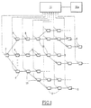
- the tree-based data transmission network shown by way of example in FIG. 1 includes a telephone exchange 2, forming a root node, which supplies a plurality of distribution centers 4.
- Each distributor center 4 in turn feeds a plurality of subscribers, connected to the network by a plurality of terminal nodes 6.
- the telephone exchange 2 constitutes the most upstream node of the network, while the terminal nodes 6 constitute the most downstream nodes of the network.
- each node except the root node i.e. the telephone exchange 2
- several nodes can have the same node dad.
- the network is made up of branches comprising nodes simple 8, that is to say nodes having at most one child node, and nodes of intersection 10, that is to say nodes comprising at least two child nodes.
- the tree network described above is associated with a system of monitoring.
- This monitoring system includes, as illustrated in the FIG. 1, means 11 for controlling the operation of each of the nodes of the network to detect a possible malfunction of these.
- These means 11 can have any conventional structure suitable for example with a computer, to trigger the operation of alarm means 11a in the event of detection of a malfunction of at least two network nodes.
- a plurality of databases 12 1 , ..., 12 i , ..., 12 n stores identification and description information for the different nodes 2, 4 , 6, 8, 10 of the network.
- Any database 12 i stores, for example, the identification and description information of a sub-network made up of the nodes supplied by a part of the distribution centers 4.
- Each dictionary 12 1 , ..., 12 i , ..., 12 n is associated with a dictionary 14 1 , ..., 14 i , ..., 14 n , in the form of a data file describing the structure of this database as well as the format of the data stored in it.
- a computer server 16 is connected to these databases, and includes a hard disk 18 which can store all of the data contained in the databases 12 1 to 12 n .
- the server 16 also comprises a computer 20, of the conventional type, comprising on the one hand means 22 for creating a single database on the hard disk 18, from the databases 12 1 to 12 n , and d on the other hand, means 24 for reconstituting and displaying part of the tree network.
- These means may generally include, for example, computer systems programmed to perform these functions.
- the means 22 of creating a single database can access the hard disk 18 in reading and writing
- the means 24 of reconstruction and visualization can only access the hard disk 18 reading.
- the structure of the single database can for example reproduce the structure of the tree network described in Figure 1.
- a first directory corresponding to telephone exchange 2 then includes as many sub-directories that there are 4 distribution centers in the tree network.
- Each subdirectory includes at least one file containing data of identification and description of each node of the subnetwork constituted by the distributor center 4 considered and all the nodes of the network located downstream of it.
- each line contains information relating to a single node, begins with a field reserved for data of identification of this node and further includes the identification data of the parent node to which this node is connected, except of course the node root.
- the server 16 is connected to a transmission network 26 information supporting the IP communication protocol ("INTERNET PROTOCOL ”).
- a remote terminal 28 comprising a display screen 30, such as a portable microcomputer associated with a conventional modem by example and with which the technician is equipped.
- the means 22 for creating the single database copy the information contained in the databases 12 1 to 12 n onto the hard disk 18.
- these means 22 copy the content of the dictionaries 14 1 to 14 n onto the hard disk 18.
- these means 22 initialize a basic index i of data and associated dictionary, at 1.
- these means 22 read from the hard disk 18 the content of the ith dictionary 14 i , describing the structure of the ith database 12 i as well as the format of the information data it contains.
- these means 22 read the content of the ith database 12 i , on the basis of the content of the ith dictionary 14 i .
- a step 42 the means 22 test the validity and the consistency of the information read. If, during this step 42, a problem appears when reading the information stored in the plurality of databases 12 1 to 12 n , we go to a step 44, during which the means 22 trigger an error signaling . Indeed, an error can notably occur in the event of the non-conformity of a dictionary with the database with which it is associated.
- step 46 during which the identification and description information contained in the i th database 12 i are brought into play. formed by the means 22 to be stored in the new single database, on the hard disk 18.
- a step 48 if the ith processed database is not the last database to be processed, the index i is incremented during a step 50 by means 22 and we return to step 38 to ensure the shaping of the information from all databases by these means 22.
- This single database created from the different databases 12 1 , ..., 12 1 , ..., 12 n is then available on the hard disk 18 for the reconstruction and the visualization of part of the network.
- the maintenance technician inputs, on its terminal 28 described above, the identification information of p malfunctioning nodes as reported by the means of control 11 and possibly the alarm means 11a.
- the means 24 compare the nodes entered with the nodes of the tree network stored in the hard disk 18. If at least one of the nodes entered does not correspond to any of the nodes on the network, returns to step 54 of entry after command by means 24 of the display an error message. Otherwise we go to an initialization step 58, during of which a node index j presenting a dysfunction is initialized to 1 by these means 24.
- the means 24 open the file of data corresponding to the distribution center 4 supplying the jth node with a malfunction. These means 24 are then placed in the middle of the file, to search for this jth node.
- a search step 62 we search, step by step, the line of the file corresponding to the sought node.
- Research is carried out by the means 24, from the line on which we are placed at the stage previous. These means 24 then read in successive stages the fields of identification of all the lines preceding and following the line on which one placed itself, moving away from a line at each stage and alternating, during in the same step, between a line preceding and a line following the line on which these means 24 were initially placed, until the line of the sought node.
- the means 24 extract the data identification of the parent node of the node that we have just found.
- the means 24 verify that this parent node is different from root node 2, to return to step 62 and continue the search, from the line corresponding to the node that we just found until we find the root node 2 to go to step 68.
- the means 24 copy the hard disk 18 information relating to all the nodes found during the steps previous 62 and 64, to reconstruct a branch of the tree network between the jth node presenting a dysfunction and the root node 2.
- step 70 the means 24 test the value of the index j. If j is strictly less than p then we increment j by a unit and we return to step 60, Otherwise, if j is equal to p, i.e. if these means 24 have reconstituted all the branches included between each node presenting a dysfunction and the root node 2, we pass to a step 74 of interconnection of the branches.
- the means 24 interconnect, in a conventional manner, the reconstituted branches having common nodes.
- the means 24 display the part of the network reconstructed on the screen 30 of the terminal 28 to update it provision of the maintenance technician who can then see the part of the network corresponding to the failing nodes.
- FIG. 5 An example of display of this part of the network on screen 30 of the terminal 28 is illustrated in FIG. 5.
- the network part between the node root and the three entered nodes 86, 88, 90 is displayed on an upper half 92 of interface 78.
- Each node is represented by a symbol, which is a function of its type.
- the lower half 96 of the interface 78 allows the display of identification and description information of any node among those displayed on the upper half 92, and in particular those relating to the node 94 on which the intervention must probably be carried out.
- This information includes for example first of all the data 98 of the node concerned, the type 100 of this node, the data 102 of the parent node of this node, as well as for example geographic location data 104 of this node. All of the information necessary for effective intervention are therefore immediately accessible.
- the interface 78 also comprises, in a conventional manner, in its part top, a menu 106 presenting various options such as for example the file search, input of alphanumeric or graphic information complementary, or the search for coordinates in a directory telephone.
- a system or a method according to the invention improves the effectiveness of an intervention when an incident occurs on a tree-like network, allowing the technician responsible for monitoring this network to immediately view node 94 causing the incident, after seizure of the nodes 86, 88, 90 presenting a dysfunction.
- the means 24 for reconstitution and display part of the network can be installed in the portable microcomputer 28.
- the latter is authorized to have read-only access to the hard disk 18 via network 26.
Landscapes
- Engineering & Computer Science (AREA)
- Computer Networks & Wireless Communication (AREA)
- Signal Processing (AREA)
- Data Exchanges In Wide-Area Networks (AREA)
Abstract
Description
- des moyens de contrôle du fonctionnement de chacun des noeuds pour détecter un dysfonctionnement d'au moins deux noeuds ; et
- des moyens d'extraction à partir des moyens de stockage d'informations, des informations d'identification et de description de chaque noeud pour lequel un dysfonctionnement a été détecté.
- on contrôle le fonctionnement de chacun des noeuds pour détecter un dysfonctionnement d'au moins deux noeuds ; et
- on extrait à partir des moyens de stockage d'informations, les informations d'identification et de description de chaque noeud pour lequel un dysfonctionnement a été détecté,
- on reconstitue et on visualise à partir de ces informations, les branches d'une partie du réseau comportant les noeuds présentant les dysfonctionnements, entre ceux-ci et au moins le premier noeud père commun à ces branches, en remontant vers le noeud racine.
- on reconstitue, de noeud en noeud père, les branches du réseau reliant chacun des noeuds de la pluralité de noeuds présentant les dysfonctionnements au noeud racine ; et
- on raccorde les branches reconstituées entre elles en fonction de leurs noeuds d'intersection communs.
- on lit tous les dictionnaires ; et
- on extrait les informations de chaque base de données indépendante en fonction des données de description du dictionnaire associé.
- des moyens de contrôle du fonctionnement de chacun des noeuds pour détecter un dysfonctionnement d'au moins deux noeuds ; et
- des moyens d'extraction à partir des moyens de stockage d'informations, des informations d'identification et de description de chaque noeud pour lequel un dysfonctionnement a été détecté.
- des moyens de reconstitution, de noeud en noeud père, des branches du réseau reliant chacun des noeuds de la pluralité de noeuds présentant les dysfonctionnements au noeud racine ; et
- des moyens de raccordement des branches reconstituées entre elles en fonction de leurs noeuds d'intersection communs.
- des moyens de lecture des dictionnaires ; et
- des moyens d'extraction des informations de chaque base de données indépendante en fonction des données de description du dictionnaire associé, extraites par les moyens de lecture.
- la figure 1 représente un schéma synoptique d'un réseau arborescent de transmission de données ;
- la figure 2 représente un schéma synoptique d'un exemple de réalisation d'un système de surveillance selon l'invention ;
- la figure 3 représente, sous forme d'un organigramme, un procédé de création d'une unique base de données comportant l'ensemble des informations d'identification et de description des noeuds de ce réseau, mis en oeuvre dans un procédé de surveillance selon l'invention ;
- la figure 4 représente, sous forme d'un organigramme, un procédé de reconstitutionet de visualisation d'une partie de ce réseau, mis en oeuvre dans un procédé de surveillance selon l'invention ; et
- la figure 5 illustre une interface de présentation d'informations générée par des moyens de visualisation du système représenté à la figure 2.
Claims (12)
- Procédé de surveillance d'un réseau arborescent de transmission de signaux électriques entre un noeud racine (2) et une pluralité de noeuds terminaux (6), ce réseau comportant une pluralité de noeuds simples (8) et de noeuds d'intersection (10) entre le noeud racine et les noeuds terminaux et étant associé à des moyens (121, ..., 12i, ..., 12n) de stockage d'informations d'identification et de description des différents noeuds (2, 4, 6, 8, 10) de celui-ci, les informations de description d'un noeud quelconque autre que le noeud racine (2) comportant en outre l'identification d'un noeud père auquel il est connecté, le procédé comportant les étapes suivantes :caractérisé en ce qu'il comporte en outre l'étape suivante :on contrôle le fonctionnement de chacun des noeuds pour détecter un dysfonctionnement d'au moins deux noeuds ; eton extrait à partir des moyens de stockage d'informations, les informations d'identification et de description de chaque noeud pour lequel un dysfonctionnement a été détecté,on reconstitue (60, 62, 64, 66, 68, 70, 72, 74) et on visualise (76) à partir de ces informations, les branches d'une partie du réseau comportant les noeuds (86, 88, 90) présentant les dysfonctionnements, entre ceux-ci et au moins le premier noeud père (94) commun à ces branches, en remontant vers le noeud racine (2).
- Procédé de surveillance d'un réseau arborescent selon la revendication 1, caractérisé en ce que ledit dysfonctionnement détecté est un dysfonctionnement d'au moins deux noeuds n'étant pas en aval l'un de l'autre.
- Procédé de surveillance d'un réseau arborescent selon l'une quelconque des revendications 1 ou 2, caractérisé en ce qu'on reconstitue et on visualise les branches d'une partie du réseau comportant les noeuds (86, 88, 90) présentant les dysfonctionnements, entre ceux-ci et le noeud racine (2).
- Procédé de surveillance d'un réseau arborescent selon la revendication 3, caractérisé en ce que l'étape de reconstitution desdites branches comporte les étapes suivantes :on reconstitue (60, 62, 64, 66, 68), de noeud en noeud père, les branches du réseau reliant chacun des noeuds de la pluralité de noeuds (86, 88, 90) présentant les dysfonctionnements au noeud racine (2) ; eton raccorde (74) les branches reconstituées entre elles en fonction de leurs noeuds d'intersection communs.
- Procédé de surveillance d'un réseau arborescent selon l'une quelconque des revendications 1 à 4, caractérisé en ce que les moyens (121, ..., 12i, ..., 12n) de stockage d'informations comportent une pluralité de bases de données indépendantes, stockant chacune une partie des informations d'identification et de description, et en ce que le procédé comporte en outre une étape préliminaire (38, 40, 42, 44, 46, 48, 50, 52) au cours de laquelle on créé une unique base de données comportant l'ensemble des informations d'identification et de description, à partir des bases de données indépendantes.
- Procédé de surveillance d'un réseau arborescent selon la revendication 5, caractérisé en ce que chaque base de données indépendante (121, ..., 12i, ...,12n) est associée à un dictionnaire (141, ..., 14i, ..., 14n) de description de sa structure et en ce que l'étape préliminaire comporte les étapes suivantes :on lit (38) tous les dictionnaires ; eton extrait (40) les informations de chaque base de données indépendante en fonction des données de description du dictionnaire associé.
- Système de surveillance d'un réseau arborescent de transmission de signaux électriques entre un noeud racine (2) et une pluralité de noeuds terminaux (6), ce réseau comportant une pluralité de noeuds simples (8) et de noeuds d'intersection (10) entre le noeud racine et les noeuds terminaux et étant associé à des moyens (121, ..., 12i, ..., 12n) de stockage d'informations d'identification et de description des différents noeuds (2, 4, 6, 8, 10) de celui-ci, les informations de description d'un noeud quelconque autre que le noeud racine (2) comportant en outre l'identification d'un noeud père auquel il est connecté, ce système comportant :caractérisé en ce qu'il comporte en outre :des moyens (11) de contrôle du fonctionnement de chacun des noeuds pour détecter un dysfonctionnement d'au moins deux noeuds ;des moyens (20) d'extraction à partir des moyens de stockage d'informations, des informations d'identification et de description de chaque noeud pour lequel un dysfonctionnement a été détecté,des moyens (24) de reconstitution et de visualisation à partir de ces informations, des branches d'une partie du réseau comportant les noeuds (86, 88, 90) présentant les dysfonctionnements, entre ceux-ci et au moins le premier noeud père (94) commun à ces branches, en remontant vers le noeud racine (2).
- Système de surveillance d'un réseau arborescent selon la revendication, caractérisé en ce que ledit dysfonctionnement détecté par les moyens (21) de contrôle de fonctionnement est un dysfonctionnement d'au moins deux noeuds n'étant pas en aval l'un de l'autre.
- Système de surveillance d'un réseau arborescent selon l'une quelconque des revendications 7 ou 8, caractérisé en ce que les moyens (24) de reconstitution et de visualisation sont adaptés pour la reconstitution et la visualisation des branches d'une partie du réseau comportant les noeuds (86, 88, 90) présentant les dysfonctionnements, entre ceux-ci et le noeud racine (2).
- Système de surveillance d'un réseau arborescent selon la revendication 9, caractérisé en ce que les moyens de reconstitution desdites branches comportent :des moyens (68) de reconstitution, de noeud en noeud père, des branches du réseau reliant chacun des noeuds de la pluralité de noeuds (86, 88, 90) présentant les dysfonctionnements au noeud racine (2) ; etdes moyens (74) de raccordement des branches reconstituées entre elles en fonction de leurs noeuds d'intersection communs.
- Système de surveillance d'un réseau arborescent selon l'une quelconque des revendications 7 à 10, caractérisé en ce que les moyens (121, ..., 12i, ...,12n) de stockage d'informations comportent une pluralité de bases de données indépendantes, stockant chacune une partie des informations d'identification et de description, et en ce que le système comporte en outre des moyens (22) de création d'une unique base de données comportant l'ensemble des informations d'identification et de description, à partir des bases de données indépendantes.
- Système de surveillance d'un réseau arborescent selon la revendication 11, caractérisé en ce que chaque base de données indépendante (121, ..., 12i, ...,12n) est associée à un dictionnaire (141, ..., 14i, ..., 14n) de description de sa structure et en ce que les moyens (22) de création d'une unique base comportentdes moyens (38) de lecture des dictionnaires ; etdes moyens (40) d'extraction des informations de chaque base de données indépendante en fonction des données de description du dictionnaire associé, extraites par les moyens de lecture.
Applications Claiming Priority (2)
| Application Number | Priority Date | Filing Date | Title |
|---|---|---|---|
| FR0011666 | 2000-09-13 | ||
| FR0011666A FR2814024B1 (fr) | 2000-09-13 | 2000-09-13 | Procede et systeme de surveillance d'un reseau arborescent et transmission de signaux electriques |
Publications (2)
| Publication Number | Publication Date |
|---|---|
| EP1189413A2 true EP1189413A2 (fr) | 2002-03-20 |
| EP1189413A3 EP1189413A3 (fr) | 2003-06-11 |
Family
ID=8854249
Family Applications (1)
| Application Number | Title | Priority Date | Filing Date |
|---|---|---|---|
| EP01402334A Withdrawn EP1189413A3 (fr) | 2000-09-13 | 2001-09-10 | Procédé et système de surveillance d'un réseau arborescent de transmission de signaux électriques |
Country Status (2)
| Country | Link |
|---|---|
| EP (1) | EP1189413A3 (fr) |
| FR (1) | FR2814024B1 (fr) |
Cited By (1)
| Publication number | Priority date | Publication date | Assignee | Title |
|---|---|---|---|---|
| CN120948614A (zh) * | 2025-10-17 | 2025-11-14 | 南通华铮隆钢业制造有限公司 | 基于超声的装配式钢结构梁柱连接性能监测方法 |
Family Cites Families (2)
| Publication number | Priority date | Publication date | Assignee | Title |
|---|---|---|---|---|
| DE4404827C2 (de) * | 1994-02-16 | 1997-04-17 | Kommunikations Elektronik | System zum Erkennen der Funktionsfähigkeit eines digitalen Fernmeldenetzes |
| US5771274A (en) * | 1996-06-21 | 1998-06-23 | Mci Communications Corporation | Topology-based fault analysis in telecommunications networks |
-
2000
- 2000-09-13 FR FR0011666A patent/FR2814024B1/fr not_active Expired - Fee Related
-
2001
- 2001-09-10 EP EP01402334A patent/EP1189413A3/fr not_active Withdrawn
Non-Patent Citations (1)
| Title |
|---|
| HEWLET-PACKARD JOURNAL, US, H-P CO. PALOALTO, vol. 47, no. 5, 1 October 1996 (1996-10-01), pages 22 - 30 |
Cited By (1)
| Publication number | Priority date | Publication date | Assignee | Title |
|---|---|---|---|---|
| CN120948614A (zh) * | 2025-10-17 | 2025-11-14 | 南通华铮隆钢业制造有限公司 | 基于超声的装配式钢结构梁柱连接性能监测方法 |
Also Published As
| Publication number | Publication date |
|---|---|
| FR2814024B1 (fr) | 2004-05-14 |
| FR2814024A1 (fr) | 2002-03-15 |
| EP1189413A3 (fr) | 2003-06-11 |
Similar Documents
| Publication | Publication Date | Title |
|---|---|---|
| JP5143265B2 (ja) | ダウンロード・ファイルの受取り方法 | |
| FR2662879A1 (fr) | Procede de maintenance centralisee, pour un reseau de telephone sans fil. | |
| EP1695485A2 (fr) | Procede de classification automatique d un ensemble d a lertes issues de sondes de detection d intrusions d un systeme de securite d information | |
| EP0566441A1 (fr) | Système, procédé et dispositif de télécollecte de données | |
| EP0599706A2 (fr) | Dispositif de traitement de l'information permettant la gestion d'une ressource informatique par un système d'administration | |
| WO2016075407A1 (fr) | Carte euicc stockant des numéros courts par profil d'abonné pour notifier un serveur de gestion d'abonnement | |
| EP2689559A1 (fr) | Procédé et dispositif de configuration sur la base de règles de gestion | |
| FR2728749A1 (fr) | Procede de commande d'un sous-systeme d'exploitation et de gestion pour un systeme n[1 d'echange de messages de signalisation | |
| WO2005109814A2 (fr) | Systeme et procede de traçabilite de contenus sur internet | |
| CA2449260A1 (fr) | Systeme et procede pour la distribution dynamique de donnees et/ou de services | |
| FR2728088A1 (fr) | Procede d'echange d'informations en mode client/serveur, entre stations reliees par un reseau de communication | |
| EP1189413A2 (fr) | Procédé et système de surveillance d'un réseau arborescent de transmission de signaux électriques | |
| KR102162825B1 (ko) | 네트워크 토폴로지 생성 장치 및 방법 | |
| WO2003061198A1 (fr) | Systeme de gestion de reseaux de transport base sur l'analyse des tendances des donnees acquise sur le reseau | |
| FR2942056A1 (fr) | Procede d'affichage, dispositif et produit programme d'ordinateur correspondant | |
| EP1010153B1 (fr) | Procede de surveillance d'equipements informatiques et systeme de mise en oeuvre | |
| EP1047222A1 (fr) | Procédé de gestion des états de fonctionnement dans un système informatique | |
| EP0809830B1 (fr) | Procede pour consulter des informations recues d'un serveur, et terminal mettant en oeuvre ce procede | |
| BE1006101A6 (fr) | Systeme de controle de processus. | |
| WO2006072696A1 (fr) | Systeme, programme et procede d'affectation de ressources | |
| EP0531177B1 (fr) | Procédé de réparation et outil de maintenance et d'aide à la réparation mettant en oeuvre le procédé | |
| BE1005873A6 (fr) | Appareil de stockage et de consultation de donnees. | |
| EP1394983B1 (fr) | Dispositif de gestion automatique d'équipements de réseau | |
| EP0730767A1 (fr) | Systeme et procede de traitement de l'information, et systemes de telecollecte de donnees incluant ce systeme | |
| WO2001071978A1 (fr) | Superviseur d'equipements, de reseaux et de services informatiques ou de telecommunication |
Legal Events
| Date | Code | Title | Description |
|---|---|---|---|
| PUAI | Public reference made under article 153(3) epc to a published international application that has entered the european phase |
Free format text: ORIGINAL CODE: 0009012 |
|
| AK | Designated contracting states |
Kind code of ref document: A2 Designated state(s): AT BE CH CY DE DK ES FI FR GB GR IE IT LI LU MC NL PT SE TR |
|
| AX | Request for extension of the european patent |
Free format text: AL;LT;LV;MK;RO;SI |
|
| PUAL | Search report despatched |
Free format text: ORIGINAL CODE: 0009013 |
|
| AK | Designated contracting states |
Designated state(s): AT BE CH CY DE DK ES FI FR GB GR IE IT LI LU MC NL PT SE TR |
|
| AX | Request for extension of the european patent |
Extension state: AL LT LV MK RO SI |
|
| 17P | Request for examination filed |
Effective date: 20030725 |
|
| AKX | Designation fees paid |
Designated state(s): DE ES GB IT |
|
| 17Q | First examination report despatched |
Effective date: 20090326 |
|
| 18D | Application deemed to be withdrawn |
Effective date: 20110402 |
|
| STAA | Information on the status of an ep patent application or granted ep patent |
Free format text: STATUS: THE APPLICATION IS DEEMED TO BE WITHDRAWN |
|
| R18D | Application deemed to be withdrawn (corrected) |
Effective date: 20110401 |