Technical Field
-
The present invention relates to a cylinder servo motor
having integrated therein a controller, a detector, a servo
motor, a ball screw nut, and a ball screw shaft.
Background Art
-
Fig. 25 shows a related-art cylinder servo motor. As
shown in the drawing, reference numeral 63 designates a motor
serving as a drive source; 64 designates a rotational speed
detector for detecting the rotational speed of the motor 63;
68 designates a ball screw shaft; 67 designates a ball screw
nut screw-engaged with the ball screw shaft 68; and 65 designates
a hollow cylinder rod. A load is connected to a load-side end
65a of the cylindrical rod 65, and an opposite end 65b of the
cylinder rod 65 is fastened to the ball screw nut 67. A rotary
shaft bearing 82 is fitted around an end 68a of the ball screw
shaft 68. A motor shaft 63a and the end 68a of the ball screw
shaft 68 are coupled together by means of a flexible coupling
70. Reference numeral 77 designates an inner ring fastening
nut. The inner ring fastening nut 77, along with an outer ring
fastening nut 76 screw-engaged with an inner peripheral wall
of a cylinder case 66, fixes the rotary shaft bearing 82. The
cylinder rod 65 is supported by a sleeve shaft bearing 83 which
is fastened to a load-side end 66a of the cylinder case 66 and
has an oil seal 84. A slide block 69 is fastened to the cylinder
rod 65 and is clearance-fitted to a keyway 66b formed in the
cylinder case 66. Reference numeral 71 designates a case, which
secures the cylinder case 66 and a motor case 72, which houses
and supports the motor 63. Reference numeral 78 designates
a hole formed in the case 71; and 79 designates a blank cap.
Reference numeral 73 designates a cover of the rotational speed
detector 64; and 74 designates a cable of the rotational speed
detector 64. Reference numeral 80 designates a power line of
the motor 63; 75 designates an amplifier serving as a controller;
and 81 designates a higher-level controller.
-
In the related-art cylinder servo motor having the
foregoing construction, power is fed to the motor 63 by way
of the amplifier 75 in accordance with an instruction output
from the higher-level controller 81, thereby rotating the motor
shaft 63 and the ball screw shaft 68. Rotation of the cylinder
rod 65 fastened to the ball screw nut 67 is stopped. Hence,
the cylinder rod 65 does not rotate in conjunction with rotation
of the ball screw shaft 68 and rotates directly along with the
ball screw nut 67, thus acting as a cylinder servo motor.
-
The ball screw shaft 68 employed in the related-art
cylinder servo motor has a lead error attributable to machining
accuracy attained during production. The lead error differs
from one ball screw shaft to another. Because of the lead error,
the location to which the cylinder rod 65 is to travel differs
from the location instructed by the higher-level controller
81. In short, the positioning accuracy becomes deteriorated.
Particularly, when a higher level of positioning accuracy is
required, a very expensive, high-precision ball screw is
required. For this reason, after having mounted a cylinder
servo motor on a machine, a machinery manufacturer or an end
user measures a distance over which the cylinder rod 65 has
actually traveled in accordance with an instruction value output
from the higher-level controller 81, through use of a
high-precision position measuring instrument such as a laser
displacement gauge. On the basis of data pertaining to the
measurement result, correction data are prepared, and the
thus-prepared data are stored in memory (not shown) provided
in the higher-level controller 81. At the time of operation
of the machine, the positioning accuracy of the machine is
improved, through use of the correction data which correspond
to the instruction value and are stored in the memory provided
in the higher-level controller 81. As mentioned above, the
machine manufacturer or an end user must possess a high-precision
position measuring instrument and perform measurement by
themselves. A high-precision adjustment technique is required,
and the time required for assembling and adjusting a machine
becomes longer.
-
When a cylinder servo motor is replaced with a new one,
the contents stored in the memory of the higher-level controller
81 differ from those required for the new cylinder servo motor.
Hence, measurement must be performed once again. A great deal
of time is required for repairing failures or changing
facilities.
-
The related-art cylinder servo requires the cable 74 for
connecting the rotational speed detector 64 and the amplifier
75, and the power line 80 for connecting the motor 63 with the
amplifier 75. The cable 74 and the power line 80 are wired
by a machinery manufacturer or an end user. Hence, there
sometimes arise problems, such as an operation failure or a
failure of the rotational speed detector 64 attributable to
incorrect wiring.
-
The motor shaft 63a of the motor 63 and the end 68a of
the ball screw shaft 68 are coupled together by means of the
flexible coupling 70. The coupling 70 requires the case 71,
and a space in the axis of ball screw shaft 68 must be ensured,
thereby increasing the overall length of the cylinder servo
motor.
-
Since the ball screw shaft 68 is inserted into the cylinder
rod 65, only a ball screw shaft which is much smaller in diameter
than the cylinder rod 65 can be used as the ball screw shaft
68. Hence, if an attempt is made to increase allowable thrust,
the cylinder servo motor becomes bulky.
-
Since the cylinder rod 65 is supported by the sleeve shaft
bearing 83, wear arises in the slide section as a result of
sliding friction. Particularly, at the time of high-speed
operation, the life span of the cylinder servo motor becomes
shorter.
-
Further, the rotation of the cylinder rod 65 is stopped
by means of the slide block 69 clearance-fitted to the keyway
66b. Hence, a contact surface of the cylinder rod 65 is abraded
by means of sliding friction, thereby resulting in an increase
in backlash.
-
Contact between the slide block 69 and the keyway 66b
arises in the form of sliding friction. Hence, at the time
of operation, excessive thrust corresponding to a friction loss
in the contact surface is required, thus deteriorating
efficiency.
-
Further, at the time of assembly of a cylinder servo motor,
the motor shaft 63a and the end 68a of the ball screw shaft
68 are coupled together by the flexible coupling 70. A set
screw (not shown) must be fastened to the flexible coupling
70, by use of a hexagonal wrench and by way of a hole 78. To
this end, the cylinder rod 65 must be moved along the axis of
the ball screw shaft 68, thereby finding a hole for the set
screw. This results in an increase in the number of assembly
steps, thereby adding to costs.
-
The present invention has been conceived to solve the
drawback set forth and is aimed at providing a cylinder servo
motor capable of eliminating a necessity of a machinery
manufacturer or an end user performing a measurement or wiring
operation for realizing a high-precision cylinder servo motor.
-
The present invention provides a compact cylinder servo
motor which can produce large thrust and a long linear stroke.
-
The present invention is also aimed at providing an
efficient cylinder servo motor having a long life span.
-
The present invention is also aimed at providing a cylinder
servo motor of superior ease of assembly.
Disclosure of the Invention
-
The present invention provides a cylinder servo motor
comprising:
- a servo motor having a rotor and a stator;
- a cylinder servo motor main unit which is connected to
a rotary shaft of the rotor of the servo motor by way of a ball
screw nut and which has a ball screw shaft, the ball screw shaft
moving in an axial direction;
- a rotation detector for detecting a rotary position of
the servo motor;
- control means for controlling the rotation detector and
the servo motor; and
- storage means which is provided in the control means and
stores a travel distance correction value to be used for
correcting the accuracy of splitting of a travel distance of
the ball screw shaft at the time of control of the servo motor,
wherein the cylinder servomotormain unit, the rotation detector,
and the control means are integrated.-
-
As a result, at the time of control of the servo motor,
the accuracy of splitting of a travel distance of the ball screw
shaft can be corrected through use of the travel distance
correction value. Thus, there can be obtained a high-precision
cylinder servo motor.
-
A necessity of measuring correction of an accumulated
lead error in a ball screw pitch of a cylinder servo motor at
a location to which the cylinder servo motor is to be shipped
is obviated, and by extension there is obviated a necessity
of a high-precision position measurement instrument being
provided at a location to which the cylinder servo motor is
to be shipped. Moreover, the time required for assembling and
adjusting a machine having the cylinder servo motor built therein
becomes shorter. Even when the cylinder servo motor is replaced,
there is obviated a necessity of again measuring correction
of an accumulated lead error in ball screw pitch at a location
to which the cylinder servo motor is to be shipped.
-
A necessity of wiring a line between the servo motor,
the rotation detector, and the control device section at a
location to which the cylinder servo motor is to be shipped
is obviated, thereby improving workability.
-
According to the present invention, the storage means
for storing the travel distance correction value is provided
on the control means for controlling the rotation detector.
-
Hence, even when the servo motor main unit and the rotation
detector have been replaced with new ones for reasons of
mechanical life, there is no necessity of again correcting an
accumulated lead error of a ball screw pitch of a cylinder servo
motor at a location to which the cylinder servo motor is to
be shipped.
-
In the cylinder servo motor according to the present
invention, the storage means for storing the travel distance
correction value is provided on the control means for controlling
the servo motor.
-
Hence, there is obviated a circuit or software for
correcting an accumulated lead error in the ball screw pitch
of the cylinder servo motor, and there can be employed a standard
device.
-
The present invention also provides a cylinder servo motor
comprising:
- a servo motor having a rotor and a stator;
- a cylinder servo motor main unit which is connected to
a rotary shaft of the rotor of the servo motor by way of a ball
screw nut and which has a ball screw shaft, the ball screw shaft
moving in an axial direction;
- an absolute rotation detector for detecting an absolute
rotary position of the servo motor;
- storagemeans for storing a per-rotation split angle error
correction value of the absolute rotation detector;
- first control means for controlling the absolute rotation
detector;
- second control means for controlling the servo motor,
wherein the cylinder servo motor main unit, the rotation detector,
the first control means, and the second control means are
integrated together, and a travel distance correction value
for correcting the accuracy of splitting of a travel distance
of the ball screw shaft at the time of control of the servo
motor is stored as being combined with the per-rotation split
angle error correction value of the absolute rotation detector.-
-
Even when the servo motor main unit and the rotation
detector have been replaced with new ones for reasons of
mechanical life, there is no necessity of again correcting an
accumulated lead error of a ball screw pitch of a cylinder servo
motor at a location to which the cylinder servo motor is to
be shipped. Since the absolute rotation detector is used, the
position of the ball screw shaft is backed up even when power
is turned off. Hence, there is no necessity of returning the
ball screw shaft to its home position. Further, the signal
output from the rotation detector to the control means of the
servo motor takes into account a travel distance correction
value to be used for correcting the accuracy of splitting of
a travel distance of the ball screw shaft. Hence, the control
means of the servo motor can handle the signal output from the
rotation detector equally with an ordinary signal which takes
into account a travel distance correction value to be used for
correcting the accuracy of splitting a travel distance of the
ball screw shaft. Control load exerted on the control means
of the servo motor is little. Hence, a servo system realizes
good trackability. The control means of the servo motor can
be embodied through use of a standard device without use of
a special correction circuit or amendment software. Even when
the control means of the servo motor is replaced and repaired,
a high degree of precision of the control device section can
be sustained.
-
Further, the storage means for storing a per-rotation
split angle error correction value of the absolute rotation
detector can be used also as the storage means for storing the
travel distance correction value to be used for correcting the
accuracy of splitting of a travel distance of a ball screw shaft.
-
The present invention also provides a cylinder servo motor
comprising:
- a servo motor having a rotor and a stator;
- a cylinder servo motor main unit which is connected to
a rotary shaft of the rotor of the servo motor by way of a ball
screw nut and which has a ball screw shaft, the ball screw shaft
moving in an axial direction;
- an absolute rotation detector for detecting an absolute
rotary position of the servo motor;
- first control means for controlling the absolute rotation
detector; and
- second control means for controlling the servo motor,
wherein
- the cylinder servo motor main unit, the rotation detector,
the first control means, and the second control means are
integrated together, and the second control means is provided
with storage means for storing the travel distance correction
value used for correcting the accuracy of splitting a travel
distance of the ball screw shaft at the control of the servo
motor.
-
-
For this reason, the signal output from the rotation
detector can be handled simultaneously with a travel distance
correction value used for correcting the accuracy of splitting
a travel distance of a ball screw shaft. Since the servo motor
section can be controlled on the basis of a correct position
of a magnetic pole. High-precision control of the cylinder
servo motor can be efficiently effected, through use of the
travel distance to be used for correcting the accuracy of
splitting a travel distance of a ball screw shaft. Further,
a circuit or software for correcting an accumulated lead error
correction in a ball screw pitch of a cylinder servo motor is
not required as control means for controlling the rotation
detector. Hence, a standard device can be used as the control
means.
-
In the cylinder servo motor according to the present
invention, the rotor of the servo motor is constituted of the
rotary shaft and a permanent magnet, the rotary shaft being
rotatably supported by a load-side bearing supported by a
load-side bracket and by a non-load-side bearing supported by
a non-load-side bracket, at least the load-side end of the rotary
shaft being released, a through hole being formed in the rotary
shaft so as to extend in an axial direction, and the permanent
magnet being disposed opposite the stator fixed to the rotary
shaft with a predetermined clearance therebetween. Further,
the ball screwnut is constituted of a ball circulation mechanism
and is mounted on a load-side shaft end of the rotary shaft.
The ball screw shaft is screw-engaged with the ball screw nut
so as to become movable in only the axial direction such that
a non-load-side shaft end of the ball screw shaft is housed
in the through hole of the rotary shaft and such that a load-side
end of the ball screw shaft protrudes from the load-side bracket.
A rotation portion of the rotation sensor is coupled to a
non-load-side portion of the rotary shaft protruding from the
hole formed in the non-load-side bracket and is covered with
a rotation sensor cover. The control means of the servo motor
is disposed on a part of the non-load-side bracket distant from
the stator, and the control means and the rotation sensor cover
are covered with a chassis to be fastened to the non-load-side
bracket.
-
Since there is obviated use of any coupling for coupling
a rotary shaft with a ball screw shaft, which would have hitherto
been employed, the cylinder servo motor becomes compact despite
having a long stroke. Hence, the cylinder servo motor is made
compact overall, and the number of components is reduced.
-
The rotation portion of the rotation sensor is doubly
covered by the rotation sensor cover and the chassis.
Accordingly, reliability of the cylinder servo motor against
an external environment is improved.
-
In the servo motor according to the present invention,
the non-load-side end of the rotary shaft and the through hole
are elongated to a position where the control means of the servo
motor is disposed. Further, in association with elongation
of the non-load-side end and elongation of the through hole,
the non-load-side shaft end of the ball screw shaft is elongated.
-
Hence, there can be provided a cylinder servo motor having
a stroke of longer linear movement even when a cylinder servo
motor of a given dimension is employed.
-
Further, in the cylinder servo motor according to the
present invention, a non-load-side of the through hole of the
rotary shaft is opened, and a cover for covering the open side
is removably provided. Further, a through hole is formed in
a portion of the chassis opposing the cover with reference to
an axial direction of the rotary shaft. Moreover, the through
hole formed in the chassis is provided with a removable cover.
-
Manual positioning of the ball screw shaft can be effected
while the cylinder servo motor is mounted on a machine, thereby
improving workability and operability. Since the cylinder
servo motor is provided with a cover for covering the open section
of the rotor shaft and a cover for covering the through hole
formed in the chassis. Reliability of the rotation section
of the rotation detector against an external environment is
improved.
-
In the cylinder servo motor according to the present
invention, the load-side shaft bearing is constituted of a ball
bearing. An outer ring of the ball bearing is fixedly sandwiched
between a shoulder section formed on an internal peripheral
wall of the load-side bracket and an outer ring fastening nut
to be screw-engaged with an internal peripheral wall of the
load-side bracket. An inner ring of the ball bearing is fixedly
sandwiched between a ball screw nut fastening shoulder section
formed on the load-side shaft end of the rotary shaft of the
servo motor and an inner ring fastening nut to be screw-engaged
with the rotary shaft of the servo motor. An inner diameter
of the inner ring of the ball bearing is made greater than an
outer diameter of the rotor of the servo motor.
-
As a result, a cylinder servo motor can be assembled from
one direction, thereby improving workability.
-
In the cylinder servo motor according to the present
invention, the ball screw nut fastening shoulder is formed on
the load-side shaft end of the rotary shaft, and a fastening
flange section is formed on the ball screw nut. A portion of
the ball screw nut is fitted into the through hole formed in
the load-side shaft end of the rotary shaft. The fastening
flange section is brought into contact with and screw-engaged
with the ball screw nut fastening shoulder section. Thereby,
the ball screw nut is fastened to the load-side shaft end of
the rotary shaft, and an oil seal is held on the load-side bracket.
A lip section of the oil seal is brought into contact with an
outer peripheral surface of the ball screw nut fastening flange.
-
As a result, the oil seal section in an axial direction
thereof can be shortened, thereby rendering the cylinder servo
motor more compact.
-
In the cylinder servo motor according to the present
invention, a ball screw nut fastening shoulder is formed on
a load-side shaft end of the rotary shaft, and a fastening flange
section is formed at a position closer to the center of the
ball screw nut. A portion of the ball screw nut is fitted into
a through hole section formed in the load-side shaft end of
the rotary shaft, and the fastening flange section is brought
into contact with and screw-engaged with the ball screw nut
fastening shoulder section. As a result, the ball screw nut
is fastened to the load-side shaft end of the rotary shaft,
and an oil seal is held on the load-side bracket. A lip section
of the oil seal is brought into contact with an outer peripheral
surface at the shaft end of the ball screw nut.
-
Hence, there is improved abrasion resistance of the oil
seal and elongate the life span of the cylinder servo motor,
because a sliding diameter of the lip section of the oil seal
becomes smaller and a circumferential speed of a contact section
becomes low.
-
In the cylinder servo motor according to the present
invention, a detent groove is formed in an outer peripheral
section of the ball screw shaft, wherein the detent groove has
substantially the same depth as that of a thread groove or a
depth shallower than that of the thread groove and extends in
an axial direction. Further, the ball screw shaft has at least
two balls to be inserted into the detent groove, and a spring
for pressing the balls toward the detent groove at all times.
The balls are disposed such that at least one of the balls is
situated in the detent groove at all times.
-
Hence, there is diminished abrasion of the contact surface,
thereby prolonging the life span of a whirl stop and diminishing
friction loss of the whirl stop (by extension, input power is
diminished, thereby realizing energy savings), because the
whirl stop makes rolling contact.
-
In the cylinder servo motor according to the present
invention, a detent groove is formed in an outer peripheral
section of the ball screw shaft, wherein the detent groove has
substantially the same depth as that of a thread groove or a
depth shallower than that of the thread groove and extends in
an axial direction. Further, the ball screw shaft has at least
one cylindrical roller which is to be inserted into the detent
groove and is longer than a screw pitch of the ball screw shaft,
and a spring for pressing the cylindrical ball toward the detent
groove at all times.
-
Hence, the overall length of a cylinder servo motor is
shortened, because one detent unit provided in the direction
of the rotary shaft acts as a whirl stop.
Brief Description of the Drawings
-
- Fig. 1 is a fragmentary longitudinal cross-sectional view
showing a cylinder servo motor according to a first embodiment
of the present invention;
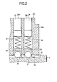
- Fig. 2 is an enlarged cross-sectional view of a load-side
shaft end section (a detent mechanism) of the cylinder servo
motor according to the first embodiment;
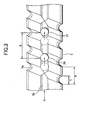
- Fig. 3 is an operation descriptive view of the detent
mechanism of the cylinder servo motor according to the first
embodiment;
- Fig. 4 is a view when viewed from direction A shown in
Fig. 3;
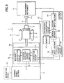
- Fig. 5 is a schematic diagram showing an electrical circuit
of the cylinder servo motor according to the first embodiment;
- Fig. 6 is a schematic diagram showing an electric circuit
required for writing, into memory, a ball screw pitch error
correction value of the cylinder servo motor according to the
first embodiment;
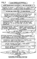
- Fig. 7 is a flowchart for describing an operation required
for writing, into memory, a ball screw pitch error correction
value of the cylinder servo motor according to the first
embodiment;
- Fig. 8 is a flowchart for describing an operation during
a normal operation of the cylinder servo motor according to
the first embodiment;
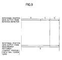
- Fig. 9 is a conceptual rendering showing computation of
a ball screw pitch error correction value of the cylinder servo
motor according to the first embodiment;
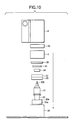
- Fig. 10 is a view showing a method of assembling the
cylinder servo motor according to the first embodiment;
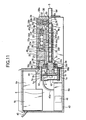
- Fig. 11 is a fragmentary longitudinal cross-sectional
view showing a cylinder servo motor according to a second
embodiment of the present invention;
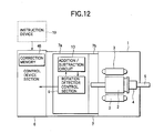
- Fig. 12 is a schematic diagram showing an electrical
circuit of the cylinder servo motor according to the second
embodiment;
- Fig. 13 is a schematic diagram showing an electric circuit
required for writing, into memory, a ball screw pitch error
correction value of the cylinder servo motor according to the
second embodiment;
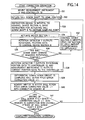
- Fig. 14 is a flowchart for describing anoperation required
for writing, into memory, a ball screw pitch error correction
value of the cylinder servo motor according to the second
embodiment;
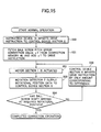
- Fig. 15 is a flowchart for describing an operation during
a normal operation of the cylinder servo motor according to
the second embodiment;
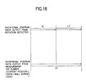
- Fig. 16 is a conceptual rendering showing computation
of a ball screw pitch error correction value of the cylinder
servo motor according to the second embodiment;
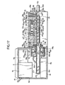
- Fig. 17 is a fragmentary longitudinal cross-sectional
view showing a cylinder servo motor according to a third
embodiment of the present invention;
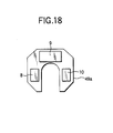
- Fig. 18 is a diagram showing the geometry of a printed
board used in a rotation sensor of the cylinder servo motor
according to a third embodiment;
- Fig. 19 is a fragmentary longitudinal cross-sectional
view showing a cylinder servo motor according to a fourth
embodiment of the present invention;
- Fig. 20 is a fragmentary longitudinal cross-sectional
view showing a cylinder servo motor according to a fifth
embodiment of the present invention;
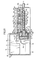
- Fig. 21 is a fragmentary longitudinal cross-sectional
view showing a cylinder servo motor according to a sixth
embodiment of the present invention;
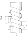
- Fig. 22 is an operation descriptive view of the detent
mechanism of the cylinder servo motor according to the sixth
embodiment;
- Fig. 23 is a view when viewed from direction B shown in
Fig. 22;
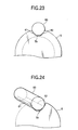
- Fig. 24 is a perspective view showing that the detent
mechanism of the cylinder servo motor according to the sixth
embodiment is in a contact state; and
- Fig. 25 is a longitudinal cross-sectional view showing
a related-art cylinder servo motor.
-
Best Modes for Implementing the Invention
First Embodiment
-
A first embodiment of the present invention will be
described by reference to Figs. 1 through 10. Fig. 1 is a
fragmentary longitudinal cross-sectional view of a cylinder
servomotor. Fig. 2 is an enlarged cross-sectional view showing
a load-side end of a shaft (a detent mechanism) ; Fig. 3 is an
operation explanatory view showing the detent mechanism; Fig.
4 is a view of the detent mechanism when viewed from direction
A shown in Fig. 3; Fig. 5 is a circuit diagram showing the
electrical circuit of a cylinder servo motor; Fig. 6 is a circuit
diagram showing an electrical circuit for writing, into memory,
a value for correcting an error in a ball screw pitch of the
cylinder servo motor (simply called a "ball screw pitch error
correction value"); Fig. 7 is a flowchart for describing an
operation for writing the ball screw pitch error correction
value into memory; Fig. 8 is a flowchart for describing operation
of the cylinder servo motor during normal operation; Fig. 9
is a conceptual rendering showing computation of a ball screw
pitch error correction value; and Fig. 10 is a view showing
a method of assembling the cylinder servo motor.
-
As shown in Fig. 1, reference numeral 1 designates a servo
motor having a rotor 2 and a stator 3. The rotor 2 of the servo
motor 1 is constituted of a rotary shaft 20 and a permanent
magnet 21 fixed on the outer peripheral section of the rotary
shaft 20. The rotor 2 is rotatably supported by a load-side
shaft bearing 22 held by a load-side bracket 28, by a load-side
shaft bearing 23 held by a non-load-side bracket 38, and by
an opposite shaft bearing 24. A non-penetrating hole 20c is
formed in the rotary shaft 20 so as to extend along the axis
of the rotary shaft 20, from a load-side shaft end 20a to a
non-load-side shaft end 20b. The non-penetrating hole 20c is
formed such that an open side is greater in diameter than a
closed side by only a predetermined amount so as to enable a
portion of a ball screw nut 4 to be described later to fit into
the open end. The larger-diameter portion of the open side
of the non-penetrating hole 20c extends to the load-side ball
bearing 22 in the axial direction. Since the ball screw nut
4 is to be fastened to the load-side shaft end 20a of the rotary
shaft 20, a shoulder section 20e is formed for securing an inner
ring 22b of the load-side ball bearing 22 and an inner ring
23b of the load-side ball bearing 23. Further, a male screw
20f with which an inner ring fastening nut 40 is to be
screw-engaged is formed in substantially the center of the rotary
shaft 20. The non-load-side shaft end 20b of the rotary shaft
20 fixes a sign board 7f of an absolute rotation detector 7
to be described later. Hence, the non-load shaft end 20b
protrudes from a hole 38b of the non-load-side bracket 38 to
the outside.
-
The stator 3 is constituted by means of winding a coil
36 around an iron core 35 and sealing the coil 36 and the iron
core 35 with resin 37. The stator 3 is fitted and fixed to
a load-side bracket 28 and the non-load-side bracket 38 and
is disposed opposite the permanent magnet 21 of the rotor 2
at a nominal radial distance.
-
Reference numeral 4 designates a ball screw nut, and balls
4a of a ball circulation mechanism (not shown) are provided
in an internal peripheral section of the ball screw nut 4.
Further, a portion of the ball screw nut 4 is fitted into an
internal peripheral section 20d of an open section of the rotary
shaft 20. A flange section 4b is brought into contact with
the shoulder 20e of the rotary shaft 20 and is secured on the
load-side shaft end 20a of the rotary shaft 20 by means of a
bolt 25 to be screw-engaged with the shoulder 20e of the rotary
shaft 20.
-
Since the construction of the ball screw nut 4 is publicly
known, detailed description of the ball screw nut 4 is omitted.
-
Reference numeral 5 designates a ball screw shaft. A
helical thread groove 5a is formed in the outer periphery of
the ball screw shaft 5 over substantially the entire length
thereof, so as to assume a predetermined lead and pitch at which
the balls 4a of the ball screw nut 4 are to fit into the thread
groove 5a. The ball screw shaft 5 is supported by the ball
screw nut 4 so as to be movable in the axial direction by way
of the balls 4a of the ball screw nut 4, such that a load-side
shaft end 5d of the ball screw shaft 5 protrudes from the load-side
bracket 28 and such that a non-load-side shaft end 5c is housed
in the deepest end of the non-penetrating hole 20c of the rotary
shaft 20. A detent mechanism, which is shown in detail in Figs.
2 through 4, prevents rotation of the ball screw shaft 5 when
the ball screw shaft 5 is moved in the axial direction.
-
The detent mechanism comprises a substantially V-shaped
single detent groove 5b; two steel balls 26 and 27; two ball
bearings 29 and 30; springs 31 and 32; and lock screws 33 and
34. The detent groove 5b is formed in the vicinity of the
load-side shaft end 5d of the ball screw shaft 5 in parallel
with the axial direction of the ball screw shaft 5. The detent
groove 5b has a depth substantially identical with the depth
of the thread groove 5a or a depth slightly shallower than the
depth of the screw thread 5a. As shown in Fig. 4, the two steel
balls 26 and 27 rotate and come into contact with the detent
groove 5b at two points. Holes 28b and 28c are formed in the
end 28a of the load-side bracket 28, and the two ball bearings
29 and 30 rotatably support the steel balls 26 and 27. The
springs 31 and 32 press the two ball bearings 29 and 30 at all
times. The lock screws 33 and 34 are screw-threaded into the
respective holes 28b and 28c formed in the end section 28a of
the load-side bracket 28, thereby adjusting a rolling contact
pressure between the detent groove 5b and the two steel balls
26and27, froma fasteningposition. As shown in Fig. 3, provided
that a pitch of the thread groove 5a is taken as P, an interval
between the steel balls 26 and 27 is taken as B, and the width
of the thread groove 5a is taken as C, the detent mechanism
assumes the relationships C<1/2P and 1.5P<B<2P. More
specifically, even when the ball screw shaft 5 is located at
an arbitrary position, there is ensured a dimensional
relationship such that at least one of the steel balls 26 and
27 is inevitably located in the detent groove 5b.
-
In relation to the load- side ball bearings 22 and 23
combined so as to support the rotary shaft 20, outer rings 22a
and 23a are fixed in the direction of the rotary shaft, by means
of a housing shoulder section 28d of the load-side bracket 28
and by means of an outer ring fastening nut 39 to be screw-engaged
with a female thread 28g formed in an internal peripheral wall
of the load-side bracket 28. Inner rings 22b and 23b are fastened
in the direction of the rotary shaft by a shoulder 20e of the
rotary shaft 20 for securing the flange 4b of the ball screw
nut 4, as well as by the inner ring fastening nut 40 to be
screw-engaged with the male screw 20f of the rotary shaft 20.
By means of setting a clamping torque of the inner ring fastening
nut 40 to a predetermined value, an axial clearance between
the load- side ball bearings 22 and 23 is eliminated. Further,
the inner diameter of the inner ring 22b of the load-side ball
bearing 22 and the inner diameter of the inner ring 23b of the
load-side ball bearing 23 are set so as to become greater than
the outer diameter of the permanent magnet 21 of the rotor 2.
-
Reference numeral 41 designates an oil seal, and the oil
seal 41 is fixedly fitted to an oil seal housing 28e of the
load-side bracket 28. A lip section 41a is in contact with
an outer peripheral section 4c of the flange section 4b of the
ball screw nut 4.
-
The cylinder servo motor is constituted of the foregoing
constituent components.
-
Reference numeral 7 designates an absolute rotation
detector, and the absolute rotation detector 7 is disposed
outside the non-load side bracket 38. The absolute rotation
detector 7 comprises a light-emitting section 7c fastened to
a non-external-side end face 38a of the non-load-side bracket
38; a sign board 7f having a predetermined pattern and a rotation
section 7b having a boss 7g; a detection section 7a, the
light-emitting section 7c of the absolute rotation detector
7 being fastened to the non-load bracket 38 by means of a screw;
and a rotation detector cover 42 for hermetically sealing the
rotation section 7b and the detection section 7a in combination
with the non-load-side bracket 38. The sign board 7f is fastened
to the boss 7g. The boss 7g is fixedly fitted to the non-load-side
shaft end 20b of the rotary shaft 20 projecting from the hole
38b of the non-load bracket 38. Thus, the boss 7g is rotatably
fastened to the non-load-side shaft end 20b of the rotary shaft
20. The detection section 7a is constituted of a
light-receiving section 7e which is mounted on a printed board
7d and opposes the light-emitting section 7c by way of the sign
board 7f; correction memory 8; a rotation detector control
section 9; and an addition/subtraction circuit 10, wherein the
memory 8, the control section 9, and the circuit 10 constitute
first control means, as shown in Fig. 5.
-
At a point in time when the rotation detector 7 is
manufactured, only a split angle correction value ε representing
the correction for each rotation of the rotation detector 7
is stored in the correction memory 8. However, at a final stage
(i.e., when the product is shipped) , a composite value consisting
of the per-rotation split angle correction value ε of the rotation
detector 7 and a ball screw pitch ε' of the ball screw shaft
5 (a travel distance correction value used for correcting the
accuracy of splitting of a travel distance of the ball screw
shaft) is stored in the correction memory 8.
-
Here, the per-rotation split angle correction value ε
is for correcting a pitch error of a split window (not shown)
provided in the sign board 7f or for correcting a per-rotation
split angle error of the sign board 7f stemming from movement
of the sign board 7f due to misalignment arising when the sign
board 7f is attached to the rotary shaft 20. At a point in
time when the rotation detector 7 is manufactured, a central
value of per-rotation split angle error of the rotation detector
7 relative to a reference split angle is sought by means of
a correction value computing unit (not shown) . The thus-sought
value is taken as a correction value.
-
Reference numeral 6 designates a control device section
which acts as second control means for controlling the position
of the servo motor 1 and which is housed and held in a chassis
43 secured on the non-external end face 38a of the non-load-side
bracket 38. The control device section 6 is constituted of
an inverter circuit 6a, a control circuit 6b electrically
connected to the inverter circuit 6a, and a power supply circuit
6c (used as a power source for the inverter circuit 6a, the
control circuit 6b, and the rotation detector 7). The inverter
circuit 6a is electrically connected to the coil 36 of the stator
3 by means of a lead wire 44, by way of a lead wire hole 38c
of the non-load-side bracket 38. The control circuit 6b is
electrically connected to the rotation detector control section
9 of the rotation detector 7 by means of a connection cable
45a and is electrically connected to the inverter circuit 6a.
Further, the control circuit 6b is electrically connected to
an external instruction device 19 by means of a connection cable
45.
-
An electric circuit and operation of the control device
section 6 are identical with those of a known control device
for a servo motor. Hence, their detailed explanations are
omitted here.
-
In order to store, into the correction memory 8 before
shipment of a product, a composite value consisting of the
per-rotation split angle correction value ε of the rotation
detector 7 and a ball screw pitch error ε' of the ball screw
shaft 5, operations such as those shown in Figs. 6, 7, and 9
are performed.
-
More specifically, as shown in Fig. 6, at a point in time
when assembly of a cylinder servo motor has finished, a
reflection mirror 11a is attached to a tip end of the ball screw
shaft 5. A laser measurement instrument 11 is disposed so as
to be able to measure a travel distance of the ball screw shaft
5. Further, there is disposed a controller 12 electrically
connected to the laser measurement instrument 11, the correction
memory 8, and a connector (not shown) (step S1 shown in Fig.
7). The controller 12 is constituted of a first input section
13, a second input section 14, a differential computing circuit
15, a control section 16, memory 17, and a memory writer 18.
-
Power of the control device section 6 is turned on, to
thereby activate the inverter circuit 6a, the control circuit
6b, and the rotation detector 7. Further, the laser measurement
instrument 11 and the controller 12 are turned on and activated.
Next, the per-rotation split angle correction value ε of the
rotation detector 7―which is stored in the correction memory
8 at a point in time at which the rotation detector 7 is shipped―is
transferred to memory 17 of the controller 12 by way of the
first input section 13 and the control section 16 (step S2 shown
in Fig. 7).
-
Then, a home position signal is input to the control device
section 6 from an instruction device 19. When the home position
signal is input to the control device section 6, the inverter
circuit 6a converts input AC power into three-phase AC power
of a desired frequency, a desired voltage, and a desired current.
The three-phase AC power is fed to the coil 36 of the stator
3 by way of the lead wire 44, thereby inducing a rotating magnetic
field. As a result, the rotor 2 is rotated, thereby returning
the servo motor 1 to its home position (step S3 shown in Fig.
7).
-
At this time, in association with rotation of the rotor
2, the ball screw nut 4 fastened to the load-side shaft end
20a is also rotated, thereby imparting thrust to the ball screw
shaft 5 by way of the balls 4a. The ball screw shaft 5 attempts
to rotate the ball screw nut 4 by means of static friction.
However, the steel balls 26 and 27 are pressed against the detent
groove 5b by means of the springs 31 and 32. Further, the interval
B between the steel balls 26 and 27 and the dimension of the
thread groove 5a assume a relationship such as that shown in
Fig. 3. At least one of the steel balls 26 and 27 remains in
the detent groove 5b, and hence the ball screw shaft 5 rotates
directly without involving rotation of the ball screw nut 4.
-
The instruction device 19 imparts to the control device
section 6 an instruction signal for actuating the ball screw
shaft 5 to a certain sampling point (step S4 shown in Fig. 7).
Upon receipt of the instruction signal, the control device
section 6 actuates the servo motor 1 in the same manner as
mentioned above (step S5 shown in Fig. 7). When the servo motor
1 is driven, the boss 7g and the sign board 7f, which are fixedly
fitted to the non-load-side shaft end 20b, also rotate. By
means of an optical signal output from the light-emitting section
7c, the light-receiving section 7e reads a pattern of the sign
board 7f. The result of reading is converted into a photocurrent.
The photocurrent is converted into a photo-voltage by means
of an analog circuit (not shown) provided on the printed board
7d, and the photo-voltage is converted into rotational position
data by means of a digital circuit (not shown) provided on the
printed board 7d. At this time, the rotation detector control
section 9 extracts the per-rotation split angle correction value
ε of the rotation detector 7 previously stored in the correction
memory 8. The rotational position data are subjected to
per-rotation split angle error correction in conjunction with
the addition/subtraction circuit 9, through use of the
correction value ε (step S6 shown in Fig. 7).
-
The rotational position data are output to the control
device section 6 (step S7 shown in Fig. 7). The control circuit
6b of the control device 6 compares the rotational position
data with the instruction signal, thus determining whether or
not the ball screw shaft 5 has arrived at a predetermined
rotational position (step S8 shown in Fig. 7). If the ball
screw shaft 5 has not yet achieved the predetermined rotational
position, power is fed to the coil 36 in order to actuate the
ball screw shaft 5, such that a difference becomes zero (step
S9 shown in Fig. 7) . More specifically, a general servo control
operation is performed.
-
When the predetermined rotational position has been
achieved, the rotation detector control section 9 outputs to
the control section 16 the rotational position data that have
been corrected by means of the per-rotation split angle
correction value ε of the rotation detector 7, by way of the
first input section 13 of the controller 12. The current
position data pertaining to the ball screw shaft 5 that are
obtained by means of the measuring instrument 11 measuring the
light reflected from the reflection mirror 11a are output to
the control section 16 by way of the second input section 14
of the controller 12 (step S10 shown in Fig. 7).
-
The rotational position data―which are input to the
control section 16 and have been corrected by the per-rotation
split angle correction value ε of the rotation detector 7―and
the current position data pertaining to the ball screw shaft
5 are output to the differential computing circuit 15 of the
controller 12. As shown in Fig. 9, the differential computing
circuit 16 computes a ball screw pitch error correction value
ε', in conjunction with the control section 16 (step S11 shown
in Fig. 7). The thus-computed ball screw pitch error correction
value ε' is temporarily stored in the memory 17.
-
As shown in Fig. 9, a+ε designates rotational position
data output from the rotational detector 7. The rotational
position data a+ε is the sum of rotational position data "a"
representing a per-rotation absolute rotational position
signal and a per-rotation split angle error correction value
ε written into the correction memory 8. Further, "b" represents
rotational position data obtained through conversion, by means
of dividing the current positional data pertaining to the ball
screw shaft 5 output from the measuring instrument 11 by the
value of a lead of the ball screw. A ball screw pitch error
correction value ε' is computed, by means of effecting
computation of b-(a+ε).
-
The control section 16 fetches the per-rotation split
angle correction value ε of the rotational detector 7 stored
in the memory 17. The thus-fetched split angle correction value
ε is combined with the previously-computed ball screw pitch
error correction value ε', thereby producing a composite value
ε+ε' (step S12 shown in Fig. 7). The memory writer 18 writes
the composite value into the correction memory 8 as combined
correction data (step S13 shown in Fig. 7).
-
Processing pertaining to steps S4 through S14 is repeated
in connection with the overall stroke of the ball screw shaft
5 until writing of ε+ε' is completed.
-
As has been described above, before shipment of a cylinder
servo motor, the composite value (ε+ε'), which consists of the
per-rotation split angle correction value ε of the rotation
detector 7 and the ball screw pitch error ε' of the ball screw
shaft 5, is stored into the correction memory 8.
-
Before storage of the composite value (ε+ε') into the
correction memory, the per-rotation split angle correction
value ε of the rotation detector 7 stored in the correction
memory 8 may be deleted or left as is after all the composite
values (ε+ε') have been stored into the correction memory. At
the time of actual operation after storage of the composite
value (ε+ε'), a readout address is taken into consideration
such that the composite value (ε+ε') is read from the correction
memory 8 and such that the thus-read composite value is used.
-
After writing of the composite value (ε+ε') has been
completed, the measuring instrument 11 and the controller 12
are removed from the servo motor.
-
As mentioned above, the cylinder servo motor according
to the first embodiment is constructed in the manner mentioned
above. During normal operation, the cylinder servo motor
operates in the manner as described in the flowchart shown in
Fig. 8.
-
The instruction device 19 imparts to the control device
section 6 an instruction signal for actuating the ball screw
shaft 5 to a certain sampling point (step S20). Upon receipt
of the instruction signal, the inverter circuit 6a converts
input AC power into three-phase AC power of a desired frequency,
a desired voltage, and a desired current. The three-phase AC
power is fed to the coil 36 of the stator 3 by way of the lead
wire 44, thereby inducing a rotatingmagnetic field. As a result,
the servo motor 1 is actuated (step S21). In association with
rotation of the rotor 2, the ball screw nut 4 fastened to the
load-side shaft end 20a is also rotated, thereby imparting thrust
to the ball screw shaft 5 by way of the balls 4a. The ball
screw shaft 5 attempts to rotate the ball screw nut 4 by means
of static friction. However, the steel balls 26 and 27 are
pressed against the detent groove 5b by means of the springs
31 and 32. Further, the interval B between the steel balls
26 and 27 and the dimension of the thread groove 5a assume a
relationship such as that shown in Fig. 3. Even when the ball
screw shaft 5 is situated at an arbitrary position, at least
one of the steel balls 26 and 27 remains in the detent groove
5b, and hence the ball screw shaft 5 rotates directly without
involving rotation of the ball screw nut 4.
-
When the servo motor 1 is driven, the boss 7g and the
sign board 7f, which are fixedly fitted to the non-load-side
shaft end 20b, also rotate. By means of an optical signal output
from the light-emitting section 7c, the light-receiving section
7e reads a pattern of the sign board 7f. The result of reading
is converted into a photocurrent. The photocurrent is converted
into a photo-voltage by means of an analog circuit (not shown)
provided on the printed board 7d, and the photo-voltage is
converted into rotational position data by means of a digital
circuit (not shown) provided on the printed board 7d. At this
time, the rotation detector control section 9 extracts composite
correction data consisting of the per-rotation split angle
correction value ε of the rotation detector 7 previously stored
in the correction memory 8 and the ball screw pitch error
correction value ε'. Along with the addition/subtraction
circuit 10, the rotation detector control section 9 computes,
as rotational position data, data that have been corrected for
a per-rotation split angle error of the rotation detector 7
and for an error in ball screw pitch, through use of the composite
correction data (step S22).
-
The thus-corrected rotational position data are output
to the control device section 6 (step 23). The control device
6 compares the rotational position data with the instruction
signal, thus determining whether or not the ball screw shaft
5 has arrived at a predetermined rotational position (step S24).
If the ball screw shaft 5 has not yet achieved the predetermined
rotational position, power is fed to the coil 36 in order to
actuate the ball screw shaft 5, such that a difference becomes
zero (step S25). More specifically, a general servo control
operation is performed.
-
When a difference between the rotational position data
and the instruction signal has become zero, power supply to
the coil 36 is disconnected, thereby actuating the ball screw
shaft 5 to the instructed position.
-
As has been described, in the first embodiment, the
accuracy of splitting of a travel distance of the ball screw
shaft 5 can be corrected at the time of control of the servo
motor 1, through use of composite correction data (ε+ε')
consisting of the per-rotation split angle correction value
ε of the rotation detector 7 and the ball screw pitch error
correction value ε'. As a result, a high-precision cylinder
servo motor can be provided.
-
A necessity of measuring correction of an accumulated
lead error in a ball screw pitch of a cylinder servo motor at
a location to which the cylinder servo motor is to be shipped
is obviated, and by extension there is obviated a necessity
of a high-precision position measurement instrument being
provided at a location to which the cylinder servo motor is
to be shipped. Moreover, the time required for assembling and
adjusting a machine having the cylinder servo motor built therein
becomes shorter. Even when the cylinder servo motor is replaced,
there is obviated a necessity of again measuring correction
of an accumulated lead error in ball screw pitch at a location
to which the cylinder servo motor is to be shipped.
-
A necessity of wiring a line between the servo motor 1,
the rotation detector 7, and the control device section 6 at
a location to which the cylinder servo motor is to be shipped
is obviated, thereby improving workability. Further, there
is obviated a necessity of discussing a location where a
controller is to be disposed, thereby improving the freedom
of mechanical design.
-
Even when a servo motor main unit and the rotation detector
7 have been replaced with new ones for reasons of mechanical
life, there is no necessity of again correcting an accumulated
lead error of a ball screw pitch of a cylinder servo motor at
a location to which the cylinder servo motor is to be shipped.
Since the absolute rotation detector 7 is used, the position
of the ball screw shaft is backed up even when power is turned
off. Hence, there is no necessity of returning the ball screw
shaft 5 to its home position. The signal output from the rotation
detector 7 to the control device section 6 takes into account
a ball screw pitch error correction value to be used for
correcting the accuracy of splitting of a travel distance of
the ball screw shaft 5. Hence, the control device section 6
can handle a signal output from the rotation detector 7 as an
ordinary signal which does not taken into account a ball screw
pitch correction value used for correcting the accuracy of
splitting of a travel distance of the ball screw shaft 5. Control
load exerted on the control device section 6 for correcting
the accuracy of splitting of a travel distance of the ball screw
shaft 5 is small. Hence, a servo system realizes good
trackability. The control device section 6 can be embodied
through use of a standard device without use of a special
correction circuit or amendment software. Even when the control
device section 6 of the servo motor is replaced and repaired,
a high degree of precision of the control device section 6 can
be sustained.
-
Storage means for storing a ball screw pitch error
correction value to be used for correcting the accuracy of
splitting of a travel distance of the ball screw shaft 5 can
double as the correction memory 8 for storing a per-rotation
split angle error correction value of an absolute rotation
detector.
-
Since the cylinder servo motor does not use any coupling
for coupling the rotary shaft 20 with the ball screw shaft 5,
which would have hitherto been employed, the cylinder servo
motor becomes compact despite having a large stroke. Hence,
the cylinder servo motor is wholly made compact, and the number
of components is reduced.
-
The electric circuit of the rotation detector 7 is doubly
covered by the rotation detector cover 42 and the chassis 43.
Further, a hole is formed in the rotary shaft 20, and the hole
is the non-penetrating hole 20c. Thus, good airtightness is
ensured, and reliability of the cylinder servo motor against
an external environment is improved.
-
As schematically shown in Fig. 10, the
previously-described components can be assembled from one
direction, thereby improving the ease of assembly of a cylinder
servo motor.
-
More specifically, in relation to the load-side bracket
28 having a detent mechanism and the oil seal 41 incorporated
therein beforehand, there can be sequentially assembled the
rotor 2 having the ball screw nut 4 and the ball screw shaft
5 incorporated therein beforehand, the load- side ball bearings
22 and 23, the non-load-side ball bearing 24, the inner ring
fastening nut 40, the outer ring fastening nut 39, the stator
3, the non-load-side bracket 38, the absolute rotation detector
7, and the control device section 6.
-
The lip section 41a of the oil seal 41 is in contact with
the outer peripheral surface 4c of the fastening flange 4b of
the ball screw nut 4. Hence, the dimension of the oil seal
section can be shortened in the axial direction, thereby
rendering the cylinder servo motor more compact.
-
Since the detent mechanism makes rolling contact,
abrasion of a contact surface is diminished, thereby prolonging
the life span of the detection mechanism and reducing friction
loss (by extension, input power is diminished, and energy savings
is attained).
Second Embodiment
-
A second embodiment of the present invention will be
described by reference to Figs. 11 through 16. Fig. 11 is a
fragmentary longitudinal cross-sectional view of a cylinder
servo motor; Fig. 12 is a schematic diagram showing the
configuration of an electric circuit of the cylinder servo motor;
Fig. 13 is a schematic diagram showing the configuration of
an electric circuit required for writing into memory a ball
screw pitch error correction value of the cylinder servo motor;
Fig. 14 is a flowchart for describing the operation of the
cylinder servo motor when the ball screw pitch error correction
value is written into memory; Fig. 15 is a flowchart for
describing the operation of the cylinder servo motor during
a normal operation; and Fig. 16 is a conceptual computation
rendering of the ball screw pitch error correction value.
-
As shown in Figs. 11 through 13, reference numeral 46
designates correction memory incorporated into the control
device section 6. A ball screw pitch error ε1' (i.e., a travel
distance correction value for correcting the accuracy of
splitting of a travel distance of a ball screw shaft) such as
that shown in Fig. 16 is stored in the correction memory 46.
The manner of storing the ball screw pitch error ε1' will be
described later.
-
In other respects, the cylinder servo motor according
to the present embodiment is substantially identical in
configuration with that described in connection with the first
embodiment, and hence repeated explanation is omitted.
-
Storage of the ball screw pitch error ε1' into the
correction memory 46 is performed in the manner as shown in
Figs. 13, 14, and 16.
-
More specifically, in the same manner as in the case of
the first embodiment, at a point in time when assembly of a
cylinder servo motor has been completed, the reflection mirror
11a is attached to a tip end of the ball screw shaft 5, as shown
in Fig. 13. Further, the laser measurement instrument 11 is
disposed so as to be able to measure a travel distance of the
ball screw shaft 5. Further, there is disposed the controller
12 electrically connected to the laser measurement instrument
11, the correction memory 8, and a connector (not shown) (step
S31 shown in Fig. 14). The controller 12 is constituted of
the first input section 13, the second input section 14, the
differential computing circuit 15, the control section 16, the
memory 17, and the memory writer 18.
-
Power of the control device section 6 is turned on, to
thereby activate the inverter circuit 6a, the control circuit
6b, and the rotation detector 7. Further, the laser measurement
instrument 11 and the controller 12 are turned on and activated.
-
Next, a home position signal is input to the control device
section 6 from an instruction device 19. When the home position
signal is input to the control device section 6, the inverter
circuit 6a converts input AC power into three-phase AC power
of a desired frequency, a desired voltage, and a desired current.
The three-phase AC power is fed to the coil 36 of the stator
3 by way of the lead wire 44, thereby inducing a rotating magnetic
field. As a result, the rotor 2 is rotated, thereby returning
the servo motor 1 to its home position (step S32 shown in Fig.
14).
-
At this time, in association with rotation of the rotor
2, the ball screw nut 4 fastened to the load-side shaft end
20a is also rotated, thereby imparting thrust to the ball screw
shaft 5 by way of the balls 4a. The ball screw shaft 5 attempts
to rotate the ball screw nut 4 by means of static friction.
However, the steel balls 26 and 27 are pressed against the detent
groove Sbbymeans of the springs 31 and 32. Further, the interval
B between the steel balls 26 and 27 and the dimension of the
thread groove 5a assume a relationship such as that shown in
Fig. 3. Hence, even when the ball screw shaft 5 is situated
at an arbitrary position, at least one of the steel balls 26
and 27 remains in the detent groove 5b, and hence the ball screw
shaft 5 rotates directly without involving rotation of the ball
screw nut 4.
-
The instruction device 19 imparts to the control device
section 6 an instruction signal for actuating the ball screw
shaft 5 to a certain sampling point (step S33 shown in Fig.
14). Upon receipt of the instruction signal, the control device
section 6 actuates the servo motor 1 in the same manner as
mentioned above (step S34 shown in Fig. 14). When the servo
motor 1 is driven, the boss 7g and the sign board 7f, which
are fixedly fitted to the non-load-side shaft end 20b, also
rotate. By means of an optical signal output from the
light-emitting section 7c, the light-receiving section 7e reads
a pattern of the sign board 7f. The result of reading is converted
into a photocurrent. The photocurrent is converted into a
photo-voltage by means of an analog circuit (not shown) provided
on the printed board 7d, and the photo-voltage is converted
into rotational position data by means of a digital circuit
(not shown) provided on the printed board 7d.
-
The rotational position data are output to the control
device section 6 (step S35 shown in Fig. 14). The control device
6 compares the rotational position data with the instruction
signal, thus determining whether or not the ball screw shaft
5 has arrived at a predetermined rotational position (step S36
shown in Fig. 14). If the ball screw shaft 5 has not yet achieved
the predetermined rotational position, power is fed to the coil
36 in order to actuate the ball screw shaft 5, such that a
difference becomes zero (step S37 shown in Fig. 14). More
specifically, a general servo control operation is performed.
-
When the predetermined rotational position has been
achieved, the rotation detector control section 9 outputs to
the control section 16 the rotational position data by way of
the first input section 13 of the controller 12. The current
position data pertaining to the ball screw shaft 5, which are
obtained by means of the measuring instrument 11 measuring the
light reflected from the reflection mirror 11a, are output to
the control section 16 by way of the second input section 14
of the controller 12 (step S38 shown in Fig. 14).
-
The rotational position data input to the control section
16 and the current position data pertaining to the ball screw
shaft 5 are output to the differential computing circuit 15
of the controller 12. As shown in Fig. 16, the differential
computing circuit 16 computes a ball screw pitch error correction
value ε1', in conjunction with the control section 16 (step
S39 shown in Fig. 14). The thus-computed ball screw pitch error
correction value ε1' is temporarily stored in the memory 17.
-
More specifically, as shown in Fig. 16, a1 designates
rotational position data representing a per-rotation absolute
rotational position signal output from the rotation detector
7. Further, "b1" represents rotational position data obtained
through conversion by means of dividing the current positional
data pertaining to the ball screw shaft 5 output from the
measuring instrument 11 by the value of a lead of the ball screw.
A ball screw pitch error correction value ε1' is computed, by
means of effecting computation of b1-a1.
-
The control section 16 fetches the ball screw pitch error
correction value ε1' temporarily stored in the memory 17. The
memory writer 18 writes the ball screw pitch error correction
value ε1' into the correction memory 46 provided in the control
device section 6 (step S40 shown in Fig. 14).
-
Processing pertaining to steps S33 through S41 is repeated
in connection with the overall stroke of the ball screw shaft
5 until writing of the ball screw pitch error correction value
ε1' is completed.
-
As mentioned above, the ball screw pitch error ε1' of
the ball screw shaft 5 is stored in the correction memory 46
before shipment of a cylinder servo motor product.
-
After writing of the ball screw pitch ε1' has been completed,
the measurement instrument 11 and the controller 12 are removed
from the cylinder servo motor.
-
Since the cylinder servo motor according to the second
embodiment of the present invention is constituted in the manner
as mentioned above, the cylinder servo motor operates according
to a flowchart shown in Fig. 15 during normal operation.
-
The instruction device 19 imparts to the control device
section 6 an instruction signal for actuating the ball screw
shaft 5 to a certain sampling point (step S50). Upon receipt
of the instruction signal, the control device section 6 fetches
the ball screw pitch error ε1' from the correction memory 46,
and the thus-fetched error is added to the instruction signal
(step S51). More specifically, a signal which is the sum of
the instruction value imparted from the instruction device 19
and the ball screw pitch error ε1' is taken as an instruction
value to be sent to a motor.
-
After completion of the processing, the inverter circuit
6a converts input AC power into three-phase AC power of a desired
frequency, a desired voltage, and a desired current. The
three-phase AC power is fed to the coil 36 of the stator 3 by
way of the lead wire 44, thereby inducing a rotating magnetic
field. As a result, the servo motor 1 is actuated (step S52).
In association with rotation of the rotor 2, the ball screw
nut 4 fastened to the load-side shaft end 20a is also rotated,
thereby imparting thrust to the ball screw shaft 5 by way of
the balls 4a. The ball screw shaft 5 attempts to rotate the
ball screw nut 4 by means of static friction. However, the
steel balls 26 and 27 are pressed against the detent groove
5b by means of the springs 31 and 32. Further, the interval
B between the steel balls 26 and 27 and the dimension of the
thread groove 5a assume a relationship such as that shown in
Fig. 3. Even when the ball screw shaft 5 is situated at an
arbitrary position, at least one of the steel balls 26 and 27
remains in the detent groove 5b, and hence the ball screw shaft
5 rotates directly without involving rotation of the ball screw
nut 4.
-
When the servo motor 1 is driven, the boss 7g and the
sign board 7f, which are fixedly fitted to the non-load-side
shaft end 20b, also rotate. By means of an optical signal output
from the light-emitting section 7c, the light-receiving section
7e reads a pattern of the sign board 7f. The result of reading
is converted into a photocurrent. The photocurrent is converted
into a photo-voltage by means of an analog circuit (not shown)
provided on the printed board 7d, and the photo-voltage is
converted into rotational position data by means of a digital
circuit (not shown) provided on the printed board 7d.
-
Next, the thus-corrected rotational position data are
output to the control device section 6 (step S53). The control
device 6 compares the rotational position data with the
instruction signal (to which the ball screw pitch error ε1'
has been added) , thus determining whether or not the ball screw
shaft 5 has arrived at a predetermined rotational position (step
S54). If the ball screw shaft 5 has not yet achieved the
predetermined rotational position, power is fed to the coil
36 in order to actuate the ball screw shaft 5, such that a
difference becomes zero (step S55). More specifically, a
general servo control operation is performed.
-
When a difference between the rotational position data
and the instruction signal has become zero, a power supply to
the coil 36 is disconnected, thereby actuating the ball screw
shaft 5 to the instructed position.
-
As has been described, in the second embodiment, the
rotational position data which has been corrected through use
of the per-rotation split angle correction value ε of the rotation
detector 7 maybe employed as the rotational position data output
from the rotation detector 7, in the same manner as in the first
embodiment. In this case, it goes without saying that the ball
screw pitch error correction value ε1' to be stored in the
correction memory 46 corresponds to data determined by
subtracting (rotational position data taking into account the
per-rotation split angle correction value ε of the rotation
detector 7) from (data obtained by means of dividing the current
positional data pertaining to the ball screw shaft 5 output
from the measurement instrument 11 by the ball screw lead and
converting the result of division into rotational position
data).
-
As has been described, in the second embodiment, the
accuracy of splitting of a travel distance of the ball screw
shaft 5 can be corrected at the time of control of the servo
motor 1, through use of the ball screw pitch error correction
value ε1'. As a result, a high-precision cylinder servo motor
can be provided.
-
A necessity of measuring correction of an accumulated
lead error in a ball screw pitch of a cylinder servo motor at
a location to which the cylinder servo motor is to be shipped
is obviated, and by extension there is obviated a necessity
of providing a high-precision position measurement instrument
at a location to which the cylinder servo motor is to be shipped.
Moreover, the time required for assembling and adjusting a
machine having the cylinder servo motor built therein becomes
shorter. Even when the cylinder servo motor is replaced, there
is obviated a necessity of again measuring correction of an
accumulated lead error in ball screw pitch at a location to
which the cylinder servo motor is to be shipped.
-
A necessity of wiring a line between the servo motor 1,
the rotation detector 7, and the control device section 6 at
a location to which the cylinder servo motor is to be shipped
is obviated, thereby improving workability. Further, there
is obviated a necessity of discussing a location where a
controller is to be disposed, thereby improving the freedom
of mechanical design.
-
There is no necessity of using, as the control section
9 for controlling the rotation detector 7, a circuit or software
for correcting an accumulated lead error in the ball screw pitch
5 of the cylinder servo motor. Hence, a standard device can
be employed as the control section.
-
Since the absolute rotation detector 7 is used, the
position of the ball screw shaft is backed up even when power
is turned off. Hence, there is no necessity of returning the
ball screw shaft 5 to its home position. An output from the
rotation detector 7 and the ball screw pitch error correction
value ε1' for correcting the accuracy of splitting a travel
distance of the ball screw shaft 5 can be handled simultaneously.
Since the servo motor section can be controlled on the basis
of the position of a correct magnetic pole, good efficiency
is achieved. Further, high-precision control of the cylinder
servo motor can be effected, through use of the ball screw pitch
error correction value ε1'used for correcting the accuracy of
splitting of a travel distance of the ball screw shaft 5.
-
Since the cylinder servo motor does not use any coupling
for coupling the rotary shaft 20 with the ball screw shaft 5,
which would have hitherto been employed, the cylinder servo
motor becomes compact despite having a large stroke. Hence,
the cylinder servo motor is wholly made compact, and the number
of components is reduced.
-
The electric circuit of the rotation detector 7 is doubly
covered by the rotation detector cover 42 and the chassis 43.
Further, a hole is formed in the rotary shaft 20, and the hole
is the non-penetrating hole 20c. Thus, good airtightness is
ensured, and reliability of the cylinder servo motor against
an external environment is improved.
-
As schematically shown in Fig. 10, the
previously-described components can be assembled from one
direction, thereby improving the ease of assembly of a cylinder
servo motor. More specifically, in relation to the load-side
bracket 28 having a detent mechanism and the oil seal 41
incorporated therein beforehand, there can be sequentially
assembled the rotor 2 having the ball screw nut 4 and the ball
screw shaft 5 incorporated therein beforehand, the load- side
ball bearings 22 and 23, the non-load-side ball bearing 24,
the inner ring fastening nut 40, the outer ring fastening nut
39, the stator 3, the non-load-side bracket 38, the absolute
rotation detector 7, and the control device section 6.
-
The lip section 41a of the oil seal 41 is in contact with
the outer peripheral surface 4c of the fastening flange 4b of
the ball screw nut 4. Hence, the dimension of the oil seal
section can be shortened in the axial direction, thereby
rendering the cylinder servo motor more compact.
-
Since the detent mechanism makes rolling contact,
abrasion of a contact surface is diminished, thereby prolonging
the life span of the detection mechanism and reducing friction
loss (by extension, input power is diminished, and energy savings
is attained).
Third Embodiment
-
A third embodiment of the present invention will be
described by reference to Figs. 17 and 18. Fig. 17 is a
fragmentary longitudinal cross-sectional view of a cylinder
servo motor, and Fig. 18 is a diagram showing the geometry of
a printed board used in the rotation detector.
-
As shown in Fig. 17, a non-load-side shaft end 47b of
a rotary shaft 47 (corresponding to the rotary shaft 20 described
in connection with the first embodiment) penetrates through
an absolute rotation detector 49 (corresponding to the absolute
rotation detector 7 described in connection with the first
embodiment) and extends to the neighborhood of an end section
6d of the control device section 6. In association with
elongation of the rotary shaft 47, a non-load-side shaft end
50c of a ball screw shaft 50 (corresponding to the ball screw
shaft 5 described in connection with the first embodiment) is
extended to the neighborhood of the non-load-side shaft end
47b of the rotary shaft 47. In order to extend the rotary shaft
47 as described above, a printed board 49d of the rotation
detector 49 is formed to assume a C-shaped geometry as shown
in Fig. 18, and a hole is formed in a rotation detector cover
52 (corresponding to the rotation detector cover 42 described
in connection with the first embodiment) so that the rotary
shaft 47 can penetrate through the hole.
-
As shown in Fig. 17, reference numeral 47a designates
a Ioad-side shaft end; 47c designates a non-penetrating hole
of the rotary shaft 47; 47d designates an internal peripheral
section of the rotary shaft 47; 47e designates a shoulder section
of the rotary shaft 47; 47f designates a boss mount section
on the rotary shaft 47; 47g designates a male screw section
of the rotary shaft 47; 48 designates a non-load-side bearing;
49a designates a detection section of the absolute rotation
detector 49; 49b designates a rotation section of the absolute
rotation detector 49; 49c designates a light-emitting section
of the absolute rotation detector 49; 49e designates a
light-receiving section of the absolute rotation detector 49;
49f designates a sign board of the absolute rotation detector
49; 49g designates a boss of the absolute rotation detector
49; 50a designates a screw thread of the ball screw shaft 50;
50b designates a detent groove of the ball screw shaft 50; 50c
designates a non-load-side shaft end of the ball screw shaft
50; 50d designates a load-side shaft end of the ball screw shaft
50; and 51 designates a rotor corresponding to the rotor 2
described in connection with the first embodiment. Since the
cylinder servo motor according to this embodiment is
substantially identical in construction with that described
in connection with the first embodiment, repeated explanation
thereof is omitted.
-
The cylinder servo motor according to the third embodiment
is identical in operation with that described in connection
with the first embodiment. By means of imparting a position
instruction to the servo motor, the ball screw shaft 50
corresponding to the ball screw shaft 5 is actuated to a
predetermined position.
-
Needless to say, the third embodiment can be applied to
the second embodiment.
-
As has been described, in addition to yielding the same
advantages as those yielded in the first and second embodiments,
the third embodiment also yields an advantage of the ability
to realize a stroke of longer linear movement even when a cylinder
servo motor of a given dimension is employed.
Fourth Embodiment
-
A fourth embodiment of the present invention will be
described through use of Fig. 19 (i.e., a fragmentary
longitudinal cross-sectional view showing a cylinder servo
motor).
-
As shown in Fig. 19, a non-load-side shaft end 53b of
a rotary shaft 53 (corresponding to the rotary shaft 47 according
to the third embodiment) penetrates through the rotation
detector 49 and is extended to the neighborhood of the end section
6d of the control device section 6. A through hole 53c is formed
in the rotary shaft 53 so as to extend from a load-side shaft
end 53a to the non-load-side shaft end 53b in the direction
of the rotary shaft 53.
-
In association with elongation of the rotary shaft 53,
the non-load-side shaft end 50c of the ball screw shaft 50 is
extended to the neighborhood of the non-load-side shaft end
53b of the rotary shaft 53. In order to elongate the rotary
shaft 53 in the manner as mentioned above, a printed board 49d
of the rotation detector 49 is produced into a C-shaped form,
as shown in Fig. 18. Further, a hole through which the rotary
shaft 53 can penetrate is formed in the rotation detector cover
52.
-
A female thread 53g is formed inside the non-load-side
shaft end 53b of the through hole 53c. A through hole cover
54 having a male screw formed thereon is removably screw-engaged
with the female thread 53g, thereby closing the non-load-side
shaft end 53b of the through hole 53c.
-
A through hole 43a opposing the through hole cover 54
is formed in the end 6d of the chassis 43, and a removable sealing
cover 43b is attached to the through hole 43a.
-
A female thread 50d is axially provided on the
non-load-shaft end 50c of the ball screw shaft 50.
-
The through hole cover 54 is provided for preventing entry
of oil or an oil mist from the through hole 53c of the non-load-side
shaft end 53b of the rotary shaft 53. Further, the sealing
cover 43b is provided for preventing entry of dust into the
through hole 43a of the chassis 43, which would otherwise cause
deterioration of the rotation section 49b of the rotation
detector 49 in an external environment. Thus, good reliability
of the cylinder servo motor against the external environment;
i.e., the same advantage as described in connection with the
first through third embodiments, can be maintained.
-
As shown in Fig. 19, reference numeral 53a designates
a load-side shaft end of the rotary shaft 53; 53c designates
a non-penetrating hole of the rotary shaft 53; 53d designates
an internal peripheral section of the rotary shaft 53; 53e
designates a shoulder section of the rotary shaft 53; 53f
designates a boss mount section of the rotary shaft 53; 53g
designates a female thread section of the rotary shaft 53; and
55 designates a rotor corresponding to the rotor 51 described
in connection with the third embodiment.
-
The cylinder servo motor according to the present
embodiment is substantially identical in configuration with
that described in connection with the third embodiment, and
hence repeated explanation thereof is omitted.
-
In the cylinder servo motor according to the present
embodiment, the sealing cover 43b is removed from the chassis
43 while the cylinder servo motor is mounted on a machine (not
shown). Subsequently, the through hole cover 54 is removed,
and an adjustment jig (not shown) on which is formed a male
screw to be screw-engaged with the female thread 50d formed
on the non-load-side shaft end 50c of the ball screw shaft 50
is attached to the ball screw shaft 50. The adjustment jig
is manually pushed and pulled, thereby enabling direct, manual
actuation of the ball screw shaft 50.
-
During normal operation of the cylinder servo motor having
an amplifier incorporated therein according to the present
embodiment, the cylinder servo motor operates in the same manner
as in the third embodiment. By means of imparting a position
instruction to the cylinder servo motor, the ball screw shaft
50 is actuated to a predetermined position.
-
It goes without saying that the third embodiment can be
applied also to the first and second embodiments.
-
In addition to yielding the same advantages as those
yielded in the first through third embodiments, the fourth
embodiment yields an advantage of the ability to enable manual
positioning of the ball screw shaft 50 while the cylinder servo
motor is mounted on a machine, thereby improving the workability
and operability of the cylinder servo motor.
Fifth Embodiment
-
A fifth embodiment of the present invention will now be
described by reference to Fig. 20 (i.e., a fragmentary
longitudinal cross-sectional view of the cylinder servo motor) .
-
As shown in Fig. 20, the oil seal 41 is fixedly fitted
to an oil seal housing 28f of the load-side bracket 28. A lip
section 41a of the oil seal 41, which is smaller in diameter
than the outer peripheral section 4c of the flange section 4b
of the ball screw nut 4, remains in contact with an external
outer peripheral surface 4d of the ball screw nut 4.
-
Since the cylinder servo motor according to the present
embodiment is substantially identical in configuration with
that described in connection with the first embodiment, repeated
explanation thereof is omitted. Moreover, the cylinder servo
motor according to the present embodiment is substantially
identical in operation with that described in connection with
the first embodiment. By means of imparting a position
instruction to the cylinder servo motor, the ball screw shaft
5 is actuated to a predetermined position.
-
Needless to say, the fifth embodiment can be applied also
to the second through fourth embodiments.
-
The lip section 41a of the oil seal 41 is held in contact
with the external outer peripheral surface 4d of the ball screw
nut 4. Hence, the sliding diameter of a contact portion of
the lip section 41a of the oil seal 41 becomes smaller, and
the peripheral speed of the contact portion also becomes smaller.
As a result, in addition to yielding the same advantages as
those yielded in the first embodiment, the fifth embodiment
yields an advantage of the ability to improve the abrasion
resistance of the oil seal 41 and to prolong the life span of
the cylinder servo motor.
Sixth Embodiment
-
A sixth embodiment of the present invention will be
described by reference to Figs. 21 through 24. Fig. 21 is a
fragmentary longitudinal cross-sectional view showing a
cylinder servo motor. Fig. 22 is an operation descriptive view
of the detent mechanism of the cylinder servo motor. Fig. 23
is a view from direction B shown in Fig. 22. Fig. 24 is a
perspective view showing that the detent mechanism of the
cylinder servo motor according to the fifth embodiment is in
a contact state.
-
As shown in Fig. 21, rotation of the ball screw shaft
5―the shaft being supported by the ball screw nut 4 by way
of the balls 4a so as to be movable in the axial direction
thereof―which would otherwise be caused when the ball screw
shaft 5 is moved in the axial direction thereof, is prevented
by a detent mechanism shown in detail in Figs. 22 through 24.
-
The detent mechanism comprises a substantially V-shaped
single detent groove 5b; one cylindrical roller 60; one roller
bearing 59; a spring 58 for pressing the cylindrical roller
60 at all times; and a lock screw 57. The V-shaped single detent
groove 5b is formed in the neighborhood of the load-side shaft
end 5d of the ball screw shaft 5 and in parallel with the axial
direction of the ball screw shaft 5. The detent groove 5b has
a depth substantially identical with the depth of the thread
groove 5a or a depth slightly shallower than the depth of the
screw thread 5a. As shown in Fig. 23, the cylindrical roller
60 comes into contact with the detent groove 5b at two contact
points 61 and 62. The roller bearing 59 is provided in a hole
56b formed in an end section 56a of the load-side bracket 56
(corresponding to the load-side bracket 28 described in
connection with the first embodiment) . The roller bearing 59
rotatably supports the cylindrical roller 60. The lock screw
57 is screw-engaged with the hole 56b formed in the end section
56a of the load-side bracket 56 and adjusts a rolling contact
pressure arising between the detent groove 5b and the cylindrical
roller 60 from a fastening position. As shown in Fig. 22,
provided that a pitch of the thread groove 5a is taken as P,
the width of the thread groove 5a is taken as C, and the length
of the cylindrical roller is taken as L, the detent mechanism
assumes a relationship 2C<L<P. More specifically, even when
the ball screw shaft 5 is located at an arbitrary position,
there is ensured a dimensional relationship such that a portion
of the cylindrical roller 60 is located in the detent groove
5b at all times.
-
As shown in Fig. 21, the housing shoulder 56d, the oil
seal housing 56e, and the female thread 56g correspond to the
housing shoulder 28d, the oil seal housing 28e, and the female
thread 56g described in connection with the first embodiment.
-
In other respects, the cylinder servo motor according
to the present embodiment is substantially identical in
configuration with that described in connection with the first
embodiment, and hence repeated explanation thereof is omitted.
-
Next will be described the operation of the cylinder servo
motor. By means of imparting a position instruction to the
cylinder servo motor, the rotor 2 and the ball screw nut 4 are
moved in the same manner as in the first embodiment. As a result
of rotation of the rotor 2 and the ball screw nut 4, thrust
is imparted to the ball screw shaft 5 by way of the balls 4a.
By means of static friction, the ball screw shaft 5 attempts
to rotate along with the ball screw nut 4. However, the
cylindrical roller 60 is pressed against the detent groove 5b
by means of the spring 58, and the relationship between the
length L of the cylindrical roller 60, the dimension C of the
thread groove 5a, and the pitch P of the thread groove 5a is
set to 2C<L<P. Hence, the contact sections 61 and 62 of the
cylindrical roller 60 inevitably remain in contact with the
detent groove 5b. Hence, the ball screw shaft 5 is actuated
to a predetermined position without involving rotation of the
ball screw nut 4.
-
Needless to say, the detent mechanism described in the
sixth embodiment can be replaced with any of those described
in connection with the second through fifth embodiments.
-
As has been described, in addition to yielding the same
advantages as those yielded in the first embodiment (excluding
the effect of the detent mechanism) , the sixth embodiment yields
an advantage of the ability to reduce the overall length of
the cylinder servo motor, because only one detection mechanism
provided in the axial direction of the rotary shaft acts as
a whirl stop.
-
In the first through fifth embodiments, the detent
mechanism is disposed in parallel with and in line with the
axial direction. If at least one ball to be brought into contact
with a detent groove is located in a section where the ball
does not cross the detent groove, the number of detent grooves
to be formed in the ball screw shaft 5 may be increased such
that two detent grooves are provided so as to oppose each other
or such that a plurality of detent grooves are provided radially.
-
In the first and second embodiments, the reflectionmirror
11a is attached to the tip end of the ball screw shaft 5, thereby
measuring a travel distance. However, if the tip end of the
ball screw shaft 5 is machined into a mirrored surface by means
of abrasion, the mirror 11a becomes unnecessary. Needless to
say, a necessity of removing the mirror 11a after measurement
becomes obviated.
-
The first through sixth embodiments have described the
built-in control device section 6. However, if a cylinder servo
motor main unit and an absolute rotation detector are integrated
together, the control device section 6 is identified by an ID
code, and the cylinder servo motor is always used in one-to-one
correspondence with the control device section 6, then the
control device section 6 may be separated rather than
incorporated. Even in the case of a cylinder servo motor of
such a type, in the present specification a cylinder servo motor
main unit, a detector, and a control device section are referred
to as being integrated.
-
As has been described, the present invention provides
a cylinder servo motor comprising:
- a servo motor having a rotor and a stator;
- a cylinder servo motor main unit which is connected to
a rotary shaft of the rotor of the servo motor by way of a ball
screw nut and which has a ball screw shaft, the ball screw shaft
moving in an axial direction;
- a rotation detector for detecting a rotary position of
the servo motor;
- control means for controlling the rotation detector and
the servo motor; and
- storage means which is provided in the control means and
stores a travel distance correction value to be used for
correcting the accuracy of splitting of a travel distance of
the ball screw shaft at the time of control of the servo motor,
wherein the cylinder servo motor main unit, the rotation detector,
and the control means are integrated. As a result, at the time
of control of the servo motor, the accuracy of splitting of
a travel distance of the ball screw shaft can be corrected through
use of the travel distance correction value. Thus, there can
be obtained a high-precision cylinder servo motor.-
-
A necessity of measuring correction of an accumulated
lead error in a ball screw pitch of a cylinder servo motor at
a location to which the cylinder servo motor is to be shipped
is obviated, and by extension there is obviated a necessity
of a high-precision position measurement instrument being
provided at a location to which the cylinder servo motor is
to be shipped. Moreover, the time required for assembling and
adjusting a machine having the cylinder servo motor built therein
becomes shorter. Even when the cylinder servo motor is replaced,
there is obviated a necessity of again measuring correction
of an accumulated lead error in ball screw pitch at a location
to which the cylinder servo motor is to be shipped.
-
A necessity of wiring a line between the servo motor,
the rotation detector, and the control device section at a
location to which the cylinder servo motor is to be shipped
is obviated, thereby improving workability.
-
According to the present invention, the storage means
for storing the travel distance correction value is provided
on the control means for controlling the rotation detector.
Hence, in addition to the foregoing advantages, the present
invention also yields an advantage that, even when the servo
motor main unit and the rotation detector have been replaced
with new ones for reasons of mechanical life, there is no
necessity of again correcting an accumulated lead error of a
ball screw pitch of a cylinder servo motor at a location to
which the cylinder servo motor is to be shipped.
-
According to the present invention, the storage means
for storing the travel distance correction value is provided
on the control means for controlling the servo motor. Hence,
in addition to the foregoing advantages, the present invention
also yields an advantage of obviating a circuit or software
for correcting an accumulated lead error in the ball screw pitch
of the cylinder servo motor and an advantage of the ability
to use a standard device.
-
The present invention also provides cylinder servo motor
comprising:
- a servo motor having a rotor and a stator;
- a cylinder servo motor main unit which is connected to
a rotary shaft of the rotor of the servo motor by way of a ball
screw nut and which has a ball screw shaft, the ball screw shaft
moving in an axial direction;
- an absolute rotation detector for detecting an absolute
rotary position of the servo motor;
- storage means for storing a per-rotation split angle error
correction value of the absolute rotation detector;
- first control means for controlling the absolute rotation
detector;
- second control means for controlling the servo motor,
wherein the cylinder servo motor main unit, the rotation detector,
the first control means, and the second control means are
integrated together, and a travel distance correction value
for correcting the accuracy of splitting of a travel distance
of the ball screw shaft at the time of control of the servo
motor is stored as being combined with the per-rotation split
angle error correction value of the absolute rotation detector.
Hence, in addition to the foregoing advantages, the present
invention also yields an advantage that, even when the servo
motor main unit and the rotation detector have been replaced
with new ones for reasons of mechanical life, there is no
necessity of again correcting an accumulated lead error of a
ball screw pitch of a cylinder servo motor at a location to
which the cylinder servo motor is to be shipped. Since the
absolute rotation detector is used, the position of the ball
screw shaft is backed up even when power is turned off. Hence,
there is no necessity of returning the ball screw shaft to its
home position. Further, the signal output from the rotation
detector to the control means of the servo motor takes into
account a travel distance correction value to be used for
correcting the accuracy of splitting of a travel distance of
the ball screw shaft. Hence, the control means of the servo
motor can handle the signal output from the rotation detector
equally with an ordinary signal which does not take into account
a travel distance correction value to be used for correcting
the accuracy of splitting a travel distance of the ball screw
shaft. Control load for correcting the accuracy of splitting
of a travel distance of the ball screw shaft exerted on the
control means of the servo motor is little. Hence, a servo
system realizes good trackability. The control means of the
servo motor can be embodied through use of a standard device
without use of a special correction circuit or amendment software .
Even when the control means of the servo motor is replaced and
repaired, a high degree of precision of the control device
section can be sustained.-
-
Further, the storage means for storing a per-rotation
split angle error correction value of the absolute rotation
detector can be used also as the storage means for storing the
travel distance correction value to be used for correcting the
accuracy of splitting of a travel distance of a ball screw shaft.
-
The present invention also provides a cylinder servo motor
comprising:
- a servo motor having a rotor and a stator;
- a cylinder servo motor main unit which is connected to
a rotary shaft of the rotor of the servo motor by way of a ball
screw nut and which has a ball screw shaft, the ball screw shaft
moving in an axial direction;
- an absolute rotation detector for detecting an absolute
rotary position of the servo motor;
- first control means for controlling the absolute rotation
detector; and
- second control means for controlling the servo motor,
wherein
- the cylinder servo motor main unit, the rotation detector,
the first control means, and the second control means are
integrated together, and the second control means is provided
with storage means for storing the travel distance correction
value used for correcting the accuracy of splitting a travel
distance of the ball screw shaft at the control of the servo
motor. In addition to the advantage of the invention, since
the absolute rotation detector is used, the position of the
ball screw shaft is backed up even when power is turned off.
Hence, there is no necessity of returning the ball screw shaft
to its home position. Further, the control means of the servo
motor can handle the signal output from the rotation detector
simultaneously with an ordinary signal which takes into account
a travel distance correction value to be used for correcting
the accuracy of splitting a travel distance of the ball screw
shaft. Since the servo motor section can be controlled on the
basis of a correct position of a magnetic pole. High-precision
control of the cylinder servo motor can be efficiently effected,
through use of the travel distance to be used for correcting
the accuracy of splitting a travel distance of a ball screw
shaft. Further, a circuit or software for correcting an
accumulated lead error correction in a ball screw pitch of a
cylinder servo motor is not required as control means for
controlling the rotation detector. Hence, a standard device
can be used as the control means.
-
-
According to the present invention, the rotor of the servo
motor is constituted of the rotary shaft and a permanent magnet,
the rotary shaft being rotatably supported by a load-side bearing
supported by a load-side bracket and by a non-load-side bearing
supported by a non-load-side bracket, at least the load-side
end of the rotary shaft being released, a through hole being
formed in the rotary shaft so as to extend in an axial direction,
and the permanent magnet being disposed opposite the stator
fixed to the rotary shaft with a predetermined clearance
therebetween. Further, the ball screw nut is constituted of
a ball circulation mechanism and is mounted on a load-side shaft
end of the rotary shaft. The ball screw shaft is screw-engaged
with the ball screw nut so as to become movable in only the
axial direction such that a non-load-side shaft end of the ball
screw shaft is housed in the through hole of the rotary shaft
and such that a load-side end of the ball screw shaft protrudes
from the load-side bracket. A rotation portion of the rotation
sensor is coupled to a non-load-side portion of the rotary shaft
protruding from the hole formed in the non-load-side bracket
and is covered with a rotation sensor cover. The control means
of the servo motor is disposed on a part of the non-load-side
bracket distant from the stator, and the control means and the
rotation sensor cover are covered with a chassis to be fastened
to the non-load-side bracket. Since there is obviated use of
any coupling for coupling a rotary shaft with a ball screw shaft,
which would have hitherto been employed, the cylinder servo
motor becomes compact despite having a long stroke. Hence,
the cylinder servo motor is made compact overall, and the number
of components is reduced.
-
The rotation portion of the rotation sensor is doubly
covered by the rotation sensor cover and the chassis.
Accordingly, reliability of the cylinder servo motor against
an external environment is improved.
-
According to the present invention, the non-load-side
end of the rotary shaft and the through hole are elongated to
a position where the control means of the servo motor is disposed.
Further, in association with elongation of the non-load-side
end and elongation of the through hole, the non-load-side shaft
end of the ball screw shaft is elongated. Hence, in addition
to the advantages set forth, the present invention yields an
advantage of the ability to realize a stroke of longer linear
movement even when a cylinder servo motor of a given dimension
is employed.
-
Further, according to the present invention, a
non-load-side of the through hole of the rotary shaft is opened,
and a cover for covering the open side is removably provided.
Further, a through hole is formed in a portion of the chassis
opposing the cover with reference to an axial direction of the
rotary shaft. Moreover, the through hole formed in the chassis
is provided with a removable cover. Accordingly, in addition
to the advantages set forth, the present invention yields an
advantage of the ability to enable manual positioning of the
ball screw shaft while the cylinder servo motor is mounted on
a machine, thereby improving workability and operability.
-
According to the present invention, the load-side shaft
bearing is constituted of a ball bearing. An outer ring of
the ball bearing is fixedly sandwiched between a shoulder section
formed on an internal peripheral wall of the load-side bracket
and an outer ring fastening nut to be screw-engaged with an
internal peripheral wall of the load-side bracket. An inner
ring of the ball bearing is fixedly sandwiched between a ball
screw nut fastening shoulder section formed on the load-side
shaft end of the rotary shaft of the servo motor and an inner
ring fastening nut to be screw-engaged with the rotary shaft
of the servo motor. An inner diameter of the inner ring of
the ball bearing is made greater than an outer diameter of the
rotor of the servo motor. As a result, in addition to the
advantages set forth, the present invention yields an advantage
of the ability to assemble a cylinder servo motor from one
direction, thereby improving workability.
-
According to the present invention, the ball screw nut
fastening shoulder is formed on the load-side shaft end of the
rotary shaft, and a fastening flange section is formed on the
ball screw nut. A portion of the ball screw nut is fitted into
the through hole formed in the load-side shaft end of the rotary
shaft. The fastening flange section is brought into contact
with and screw-engagedwith the ball screw nut fastening shoulder
section. Thereby, the ball screw nut is fastened to the
load-side shaft end of the rotary shaft, and an oil seal is
held on the load-side bracket. A lip section of the oil seal
is brought into contact with an outer peripheral surface of
the ball screw nut fastening flange. As a result, in addition
to the advantages set forth, the present invention yields an
advantage of the ability to shorten the oil seal section in
an axial direction thereof, thereby rendering the cylinder servo
motor more compact.
-
According to the present invention, a ball screw nut
fastening shoulder is formed on a load-side shaft end of the
rotary shaft, and a fastening flange section is formed at a
position closer to the center of the ball screw nut. A portion
of the ball screw nut is fitted into a through hole section
formed in the load-side shaft end of the rotary shaft, and the
fastening flange section is brought into contact with and
screw-engaged with the ball screw nut fastening shoulder section.
As a result, the ball screw nut is fastened to the load-side
shaft end of the rotary shaft, and an oil seal is held on the
load-side bracket. A lip section of the oil seal is brought
into contact with an outer peripheral surface at the shaft end
of the ball screw nut. Hence, in addition to the advantages
set forth, the present invention yields an advantage of the
ability to improve abrasion resistance of the oil seal and
elongate the life span of the cylinder servo motor, because
a sliding diameter of the lip section of the oil seal becomes
smaller and a circumferential speed of a contact section becomes
low.
-
According to the present invention, a detent groove is
formed in an outer peripheral section of the ball screw shaft,
wherein the detent groove has substantially the same depth as
that of a thread groove or a depth shallower than that of the
thread groove and extends in an axial direction. Further, the
ball screw shaft has at least two balls to be inserted into
the detent groove, and a spring for pressing the balls toward
the detent groove at all times. The balls are disposed such
that at least one of the balls is situated in the detent groove
at all times. Hence, in addition to the advantages set forth,
the present invention yields an advantage of diminishing
abrasion of the contact surface, thereby prolonging the life
span of a whirl stop and diminishing friction loss of the whirl
stop (by extension, input power is diminished, thereby realizing
energy savings), because the whirl stop makes rolling contact.
-
According to the present invention, a detent groove is
formed in an outer peripheral section of the ball screw shaft,
wherein the detent groove has substantially the same depth as
that of a thread groove or a depth shallower than that of the
thread groove and extends in an axial direction. Further, the
ball screw shaft has at least one cylindrical roller which is
to be inserted into the detent groove and is longer than a screw
pitch of the ball screw shaft, and a spring for pressing the
cylindrical ball toward the detent groove at all times. Hence,
in addition to the advantages set forth, the present invention
yields an advantage of shortening the overall length of a
cylinder servo motor, because one detent unit provided in the
direction of the rotary shaft acts as a whirl stop.
Industrial Applicability
-
As has been described, a cylinder servo motor according
to the present invention is suitable for use with a measuring
instrument, a spot welding machine, an NC machine, and a plant.