EP1189126B1 - Procédé de surveillance d'une installation - Google Patents
Procédé de surveillance d'une installation Download PDFInfo
- Publication number
- EP1189126B1 EP1189126B1 EP20010810783 EP01810783A EP1189126B1 EP 1189126 B1 EP1189126 B1 EP 1189126B1 EP 20010810783 EP20010810783 EP 20010810783 EP 01810783 A EP01810783 A EP 01810783A EP 1189126 B1 EP1189126 B1 EP 1189126B1
- Authority
- EP
- European Patent Office
- Prior art keywords
- model
- operating
- value
- variables
- determined
- Prior art date
- Legal status (The legal status is an assumption and is not a legal conclusion. Google has not performed a legal analysis and makes no representation as to the accuracy of the status listed.)
- Expired - Lifetime
Links
Images


Classifications
-
- G—PHYSICS
- G05—CONTROLLING; REGULATING
- G05B—CONTROL OR REGULATING SYSTEMS IN GENERAL; FUNCTIONAL ELEMENTS OF SUCH SYSTEMS; MONITORING OR TESTING ARRANGEMENTS FOR SUCH SYSTEMS OR ELEMENTS
- G05B23/00—Testing or monitoring of control systems or parts thereof
- G05B23/02—Electric testing or monitoring
- G05B23/0205—Electric testing or monitoring by means of a monitoring system capable of detecting and responding to faults
- G05B23/0218—Electric testing or monitoring by means of a monitoring system capable of detecting and responding to faults characterised by the fault detection method dealing with either existing or incipient faults
- G05B23/0221—Preprocessing measurements, e.g. data collection rate adjustment; Standardization of measurements; Time series or signal analysis, e.g. frequency analysis or wavelets; Trustworthiness of measurements; Indexes therefor; Measurements using easily measured parameters to estimate parameters difficult to measure; Virtual sensor creation; De-noising; Sensor fusion; Unconventional preprocessing inherently present in specific fault detection methods like PCA-based methods
-
- G—PHYSICS
- G05—CONTROLLING; REGULATING
- G05B—CONTROL OR REGULATING SYSTEMS IN GENERAL; FUNCTIONAL ELEMENTS OF SUCH SYSTEMS; MONITORING OR TESTING ARRANGEMENTS FOR SUCH SYSTEMS OR ELEMENTS
- G05B17/00—Systems involving the use of models or simulators of said systems
- G05B17/02—Systems involving the use of models or simulators of said systems electric
Definitions
- the invention relates to a method for monitoring a system with several subsystems according to the preamble of the independent claim.
- Systems such as water or gas turbines with downstream generators for generating electrical energy in power plants, turbo and reciprocating compressors for the compression of gases, pump systems or aircraft engines are typically quite complex systems that often operate at different operating points and their respective operating state by a large number of Process variables is influenced. It is usually necessary to monitor the state of such systems in order to detect malfunctions, ie deviations from the normal operating behavior, as early as possible, or to monitor the state of wear of individual components, so that necessary maintenance work can be planned in good time and carried out efficiently.
- a plurality of process variables such as pressure, temperatures at different locations of the plant, flow rates, speeds, powers, storage temperatures, etc.
- process variables such as pressure, temperatures at different locations of the plant, flow rates, speeds, powers, storage temperatures, etc.
- z. B. stored as a function of time or represented graphically.
- process variables such as pressure, temperatures at different locations of the plant, flow rates, speeds, powers, storage temperatures, etc.
- z. B. stored as a function of time or represented graphically.
- a respective residual is determined, and the model is optimized by determining model parameters such that a model error determinable from the residuals becomes minimal.
- a model structure usually a simple mathematical relationship is chosen, which is usually without physical meaning.
- At least one monitored variable is determined with the aid of the model for the operating behavior at predefinable time intervals, which is independent of the current operating point.
- This monitoring variable is preferably the residual, which results from the difference between the respectively current measured value and the model value corresponding to it.
- the time course of the monitored variable is used to assess the wear in the subsystems of the system and / or to detect malfunctions.
- EP-A-0 895 197 has the advantage of being essentially free of physical modeling and therefore very simple and suitable for industrial applications. In addition, it takes into account the current operating point of the system and can also detect slowly progressive changes, such as those caused by wear, at an early stage. As a result, complex systems can be reliably monitored. Furthermore, an efficient planning of the maintenance work is possible, which leads to a reduction of the maintenance and operating costs.
- the method according to the invention comprises the following steps: During the operation of the system, measured values are respectively recorded for a defined set of process variables at predefinable time intervals.
- the measured values acquired in a learning phase for different operating points are used to generate models for the operating behavior of the subsystems, wherein the input variables of each model are at least part of the process variables and the output variable of each model comprises a model value for at least one of the process variables Compare the model values with the readings to be optimized.
- at least one monitoring variable is determined with the aid of the models at predeterminable time intervals, which is independent of the respective current operating point and the time profile of the monitored variable is used to monitor the system.
- a preliminary test is carried out in which It is checked whether at least the measured values for those process variables which are operating variables are within a predetermined range.
- the method according to the invention is based on that the measured values for the operating and / or environmental variables are subjected to a preliminary test before they are used as input variables for the specific models for the various subsystems.
- operating variables are meant those process variables which describe the operating state of the entire system, which are therefore not specific to an individual subsystem.
- environmental variables are meant those process variables which are at least approximately not affected by the operation of the plant, for example, the air temperature outside the plant. Since at least one operating variable is usually included in each specific model for the operating behavior of a subsystem, pre-testing of the measured values for the operating variables makes it possible to prevent erroneous input variables from being used for the models of the subsystems. It is thus ensured that only those models are evaluated for the subsystems, which have trouble-free environmental and operating variables as input variables.
- the diagnostic capability of the method is improved considerably, because if, based on a model for a subsystem, a deviation from the normal operating behavior, eg. B. a fault, a fault or high wear is detected, it is certain that the error or the wear is actually present in this subsystem, and that it is not based on a fault liability of a farm size. Thus, the probability of a false alarm is drastically reduced.
- a deviation from the normal operating behavior eg. B. a fault, a fault or high wear
- the operating variables and / or the environmental parameters are already checked for errors in the preliminary test and only then are the subsystems checked with the operating or environmental variables classified as interference-free, fault-free fault isolation or fault identification is also possible. If the error already appears during the preliminary test, one of the measured values must be the Operating variables are subject to errors or an error has occurred when determining a measured value for an environmental variable.
- the method according to the invention thus performs the monitoring quasi-divided.
- the operating variables describing the operating state of the entire system are checked, and only then are the specific models for the operating behavior of the subsystems evaluated with the operating variables classified as interference-free.
- the deviation from the normal operating behavior is caused only by a subsystem or by a plurality of subsystems or by a faulty operation of an operating variable or an environmental variable.
- a machine model is determined for the pre-test whose input variables are operating variables and whose output variables comprise a machine model value for at least one of the operating variables.
- a machine model represents a relatively simple and reliable method for checking the operating variables for fault liability.
- the machine model comprises at least one model with which a machine model value for the deviation of the measured value for an operating variable from a theoretically determined desired value for this operating variable is determined.
- this model therefore, the deviation of the respective current measured value from a theoretically determined desired value is modeled. Then, this model value for the deviation is compared with the actual value of the deviation. It has been shown that the deviation of the measured value from the theoretical value can be modeled much easier and such a model provides more reliable statements.
- the model for the deviation of the measured value from the theoretically determined desired value is preferably an experimental model, which is created and optimized on the basis of the measured values acquired in the learning phase.
- the machine model can be created in the same or similar way as the models for the operating behavior of the subsystems.
- the machine model can be created from the measured values acquired during the learning phase for different operating points, a deviation quantity being determined by comparing the machine model value with the actual measured value corresponding thereto, and model parameters of the machine model being optimized such that one of the deviation quantities determinable model error becomes minimal.
- the environmental variables are also checked for freedom from interference, for example by redundant measurement or by plausibility checks.
- the preliminary check comprises an area test in which it is checked whether individual or combinations of operating variables lie within the range of operating points learned in the learning phase. This can in fact prevent that "unskilled" states of the system lead to false warnings.
- only the models for the subsystems are evaluated after the preliminary test, in which only process variables are received, for which no error or no fault is detected in the pre-test. This measure avoids unnecessary calculation or evaluation effort.
- a further advantageous measure is to set a confidence interval for at least one monitoring variable, to increase this confidence interval if the size of the surveillance leaves the original confidence interval and to register the increase in the confidence interval.
- the plant to be monitored is a turbine with a generator for generating electric energy driven by it, as used in hydropower plants.
- the invention is not limited to such applications, the plant to be monitored may for example also be a gas turbine with a downstream generator, a turbo or piston compressor for compressing gases, a pump system or an aircraft engine.
- subsystem refers to parts of the plant, subsystems or individual components which are described by process variables between which a physical relationship exists. It may be in such a subsystem to a concrete structurally related component system, such as the component system "thrust bearing", which z. B. is characterized by different storage temperatures as process variables. It may also be a functionally coherent subsystem, for example, the subsystem "cooled thrust bearing”, which in addition to the storage temperatures by other process variables, such. As oil temperature, cooling water temperature and power is characterized.
- process variable is meant generally a quantity of a set of physical quantities, which entity in this application describes the operating state of the plant and its subsystems or subsystems.
- the process variables are thus directly or indirectly detectable variables that are useful for characterizing the operating state of the plant or its subsystems or have an influence on the operating state of the plant.
- process variable includes the following quantities: power, stator position, impeller height, pressure upstream and downstream of the turbine, flow rate of the water, temperature of the water, speed of the turbine, temperature of the cooling medium, Temperature in the generator, temperatures in shaft bearings or seals, noise emissions, vibration, blade positions, etc.
- process variables can be directly influenced by operators, such as the turbine's flow of water, other process variables such as shaft bearing temperature or shaft seal temperature , are not directly influenced.
- process variables such as shaft bearing temperature or shaft seal temperature
- process variables There are three different types of process variables, namely the environmental variables, the operating variables and the component sizes.
- the environmental variables are those process variables which are approximately not influenced by the operation of the system, for example the water temperature in the inlet or the air temperature outside the system or building in which the system is located.
- the operating variables are those process variables which describe the operating state of the entire system.
- the operating variables have the property that they are approximately uncorrelated to the environmental variables, and that there are approximately static relationships between them. Examples of operating variables are the Power, the stator position, the impeller position, the drop height of the water, the flow or the efficiency.
- the component sizes are those process variables that are not environmental or operating variables. They are variables specific to a subsystem, for example, bearing temperatures, process variables that describe the oil lubrication and oil cooling system, oil pressure. Component sizes can be locally, that is, limited to the subsystem that they describe, the importance of operating variables for this subsystem.
- operating point or “operating point” is meant that operating state in which the system is currently operating.
- Each combination of process variables that can be realized with the system corresponds to one operating point.
- the totality of possible operating points is referred to as operating range.
- the operating point of the system can be specified by the operator by directly influenceable process variables are set to the desired value. For example, if the turbine is operating in part-load mode, it operates at a different operating point than in full-load operation.
- the operating point of the system is determined by the operating and environmental parameters.
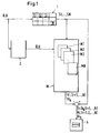
- Fig. 1 illustrates in a schematic block diagram, the concept of an embodiment of the inventive method.
- the system to be monitored in this case the turbine-generator unit, is denoted overall by the reference numeral 1 and comprises a total of N subsystems 11, 12,..., 1N, where N is an arbitrary natural number.
- N is an arbitrary natural number.
- measured values are acquired during the operation of the system 1 for a defined set of process variables B, U, S1, S2,..., SN at predeterminable time intervals, for example every minute or every 10 minutes.
- the process variables B are operating variables, for example the flow, the impeller position, the stator position, the electrical terminal capacity of the generator, the net height of the water.
- the process variables U are environmental variables, for example the temperature of the ambient air or the water temperature in the inlet.
- Each of these models Mi has as input variables, in addition to the component sizes Si of this subsystem 1i, at least one but usually more of the operating variables B and optionally one or more environmental variables U.
- the operating variables B thus enter into several or all of the models Mi.
- the entirety of the models Mi is designated M in FIG.
- the monitoring variables Ri are preferably residuals which result from subtraction from the respectively current measured values for the component quantities Si and the associated model values Yi.
- the time course of the monitoring quantities Ri is used for monitoring and for the diagnosis of the plant.
- the time profile of the monitored variables Ri is graphically displayed on an output unit 4.
- the wear can be assessed and malfunctions can be detected.
- wear are meant operationally, usually slowly progressive changes, for example in the shaft bearing or in the shaft seals and z. B.Dracks in lines or contamination of filters.
- Malfunctions can be, for example, failures or malfunctions of one of the sensors or the actuators they monitor (eg valves, control valves) or faults in the system 1, such as changes in vibrations or overheating of bearings or seals.
- a preliminary test 2 is carried out before determining the monitored quantities Ri, in which it is checked whether at least the measured values for those process variables which are operating variables B are within a predetermined range.
- This measure can significantly increase the efficiency of the process. Since the current measured values for the operating variables B are respectively checked in the operating phase of the system 1 before the models Mi are evaluated for the subsystems 1i, it is prevented that errors in the operating variables B in the models Mi for the subsystems 1i propagate and increase False alarms or lead to misdiagnosis.
- the pre-examination 2 and the subsequent execution of the models Mi for the subsystems 1i enable the identification of faulty process variables (fault isolation) reliably and in a simple manner.
- the pre-test 2 of the operating variables B also increases the reliability of the wear monitoring for the individual subsystems 1i and thus significantly facilitates the planning of maintenance work.
- the method according to the invention can be divided into two phases, namely a learning phase and an operating phase.
- the learning phase serves to create the models Mi for the subsystems 1i and in the operating phase the system 1 is monitored by means of the models Mi.
- the models Mi for the subsystems 1i based on in the learning phase determined measured values for the process variables can be determined in detail in the already cited EP-A-0 895 197 and is therefore only briefly outlined here. For further information, see EP-A-0 895 197, which is incorporated herein by reference.
- the learning phase refers to a time-limited period of operation of the system 1, during which the system 1 operates in normal, ie trouble-free operation. The choice of the learning phase can be based on experience. For example, after commissioning or a revision of the system 1, it is necessary to wait until typical run-in processes have been completed.
- the learning phase is chosen to be so long that it comprises several different operating points from the operating range of Appendix 1, that is, during the learning phase, the system is operated at a variety of different operating points, whereby it is always ensured by checks that the system 1 during the learning phase works error-free or that only such measured values are used for the creation of the model Mi, in the acquisition of the plant 1 has worked error-free and trouble-free.
- At least one of the component sizes is selected from the set of component sizes Si which describe this subsystem 1i Si k is called.
- a model value Yi k is determined by means of the model Mi.
- input variables of the model Mi at least a part of the component sizes Si of this subsystem 1i as well as operating variables B and possibly even environmental quantities U are used.
- a plurality of sets (B, U, Si) T of measured values for the process variables B, U, Si are collected and stored, wherein the index T indicates the chronologically successive measured value sets (B, U, Si) T.
- a linear static model structure is chosen in the simplest case, that is, the process variable Si k is represented as a linear combination of the input variables of the model Mi.
- the coefficients of this linear combination denoted by a m , where m is a running index, are the model parameters for the model Mi.
- the sets (B, U, Si) T of measured values provide the determination equations for the model parameters a m . Since, as a rule, the number of sets of measured values is considerably greater than the number of model parameters a m , the system of determining equations is overdetermined. However, sufficient mathematical methods are known for determining the best possible values for the model parameters a m by means of the determination equations. Examples of suitable methods are the Equalization Calculation Method, the least squares method, the Singular Value Decomposition (SVD) method or the Principal Component Analysis (PCA). Since such methods are well known, they will not be explained in detail here.
- Means of the model Mi, the associated model value (Yi k) T as the linear combination of the process parameters B, U, Si is now determined by the coefficients a m for each set (B, U, Si) T.
- the (Yi k ) T form a set of model values, where (Yi k ) T is the model value for the component size Si k for the time T.
- the model values (Yi k ) T are compared with the actual measured values for the component size (Si k ) T corresponding to them by subtraction and from these a residual r T is determined.
- the totality of the residuals r T becomes a model error ⁇ determined, which is a measure of the goodness of the model Mi.
- the model error ⁇ can be, for example, the normalized sum of the squares of the residuals.
- the model Mi is optimized until the model error ⁇ is minimal or falls below a predetermined limit. When this is achieved, the model Mi is good enough for monitoring.
- the fluctuations of the residuals r T determined during the learning phase represent how strong the deviation of the model value Yi k from the actual measured value Si k is typically. Therefore, in the normal operating phase, the confidence ranges of the models or the threshold values for the monitored variable are preferably determined on the basis of the residuals r T determined in the learning phase.
- Preliminary test 2 comprises the following components: a machine model MA, its input variables Operating variables B and whose output variables include a machine model value YA for at least one of the operating variables; an area test 21, in which it is checked whether individual or combinations of operating variables lie within the range of operating points learned in the learning phase; a test 22, with which the environmental variables are checked for freedom from interference.
- the machine model MA is based essentially on the same concept as the models Mi for the subsystems 1i.
- the machine model MA has operating variables B as input variables for which measured values are recorded at regular intervals by means of the sensors.
- the task of the machine model MA is to calculate machine model values for one or more selected operating variables, which can then be compared with the corresponding measured values for the operating variables.
- the machine model MA calculates a machine model value YA for only one selected operating variable B.
- machine model values YA are used with the machine model or machine models MA for those operating variables B, which are used as input variables for the models Mi of the subsystems 1i.
- the operating variables electrical terminal power P of the generator and flow Q are used as output variables for the machine model MA, because together with the height of fall H and P represent the most important operating variables, which are usually for each model Mi of the subsystems 1 i are used as input variables.
- the machine model MA like the models Mi for the subsystem, is created on the basis of measured values, which are recorded and stored during the learning phase.
- the machine model MA additionally basic knowledge about the system 1 and prior knowledge, z. B. from model experiments introduced.
- the machine model MA in contrast to the models Mi no purely experimental model, but also takes into account known physical relationships between the operating variables B and prior knowledge of the Appendix 1.
- FIG. 3 schematically illustrates a specific exemplary embodiment for the implementation of the machine model MA. It serves to check the operating variable P, which is the electrical terminal power of the generator, for freedom from interference.
- PI is the actual value of the operating variable P, which is metrologically detectable
- PS the target value of P, which is calculated theoretically based on basic and prior knowledge, depending on operating variables B.
- This desired value PS is calculated theoretically by a module 31.
- the module 31 may include, for example, a physical model. It is also possible that the module 31 evaluates known physical relationships or empirically determined relationships between operating variables or prior knowledge of the system 1.
- the module 31 delivers a nominal theoretical value PS for the terminal power as a function of the operating variables of the rotor position LA, the stator position LE and the net height HN, whose current values are recorded by measurement. In this calculation, further quantities can be taken into account, such as the numerical description of the efficiency shell curves ⁇ h (LA, LE, HN) of the turbine, the efficiency ⁇ g of the generator and mechanical losses PM.
- the difference DP is determined from the metrologically recorded actual value PI and the theoretically calculated desired value PS.
- This difference DP is also an operating variable B, which serves in the embodiment described here to check the freedom from interference of the operating variable P.
- model parameters b0, b1, b2, b3, b4 of the model ME are now determined and optimized in the same way as for the models Mi of the subsystems 1 i.
- the model ME is thus an experimental model with which the deviation DP of the operating variable P is modeled from a theoretically determined desired value.
- a plurality of sets (LE, LA, HN, PI) T of measured values for the operating variables LE, LA, HN, PI are collected and stored, the index T being the chronologically successive measured value sets (LE, LA, HN, PI) T indicated.
- the module 31 calculates the associated theoretical target value (PS) T.
- PS theoretical target value
- the sets (LE, LA, HN) T together with the associated value (PS) T provide the determinative equations for the model parameters b0 to b4.
- a machine model value (YA) T for the deviation of the actual value PI of the power from the desired value PS of the power.
- a model error ⁇ is determined which implies a Measure of the quality of the model ME is.
- the model error ⁇ may be the normalized sum of the squares of the residuals.
- the model ME is optimized until the model error ⁇ is minimal or falls below a predetermined limit. When this is achieved, the model ME is good enough.
- the respectively current machine model value YA for the difference DP between the measured power PI and the desired value PS of the power is determined within the scope of the preliminary test 2 at predetermined time intervals with the aid of the machine model MA.
- This machine model value YA is compared with the corresponding current measured value of this operating variable DP and from this a residuum RA for the system 1 is determined, eg. B. by subtraction (point 33 in Fig. 3).
- This residual RA represents a monitoring variable. If the residual RA is within a predetermined range, the so-called confidence interval, the operating variable P is classified as interference-free or error-free. Otherwise, a warning will be given as explained later.
- Causes of such a warning may be, for example: a disturbance of HN due to contamination of holes and pipes or due to air entrapment; Disturbances of LA or LE; Disturbance in the measurement of the power PI; Waste of the hydraulic efficiency ⁇ h or the efficiency ⁇ g of the generator; excessive bearing power loss, mechanical damage.
- machine models MA can also be created on the basis of the measured values recorded in the learning phase and on the basis of basic knowledge or prior knowledge of the system 1.
- a model (corresponding to the model ME in FIG. 3) is preferably created with which a machine model value for the deviation DQ of the theoretically calculated flow QS from the actual, metrologically detected flow QI can be determined. This machine model value is then compared with the actual deviation of the theoretical flow from the measured flow analogous to that shown in Fig. 3.
- area test 21 (see FIG. 2) of preliminary test 2, it is checked whether individual or combinations of operating variables B are within the range of operating points learned in the learning phase. Primarily, range test 21 should prevent unskilled states from leading to high residuals and thus false warnings.
- Each class 51 corresponds to a combination of the three operating variables LA, LE, HN, in which both LA and LE as well as HN each lie in a certain value range. Thus, any combination of values for LA, LE, HN can be classified into one of the classes 51.
- the system 1 is operated at many different operating points, so that different combinations of the values for the operating variables LA, LE, HN occur. For each error-free combination of LA, LE, HN detected during the learning phase, it is decided to which class 51 it is to be assigned. After determining the class 51 into which the combination of LA, LE, HN is to be classified, the probability of arrival of a combination belonging to that class is assessed on the basis of the relative frequency calculated from the histogram 5 in this class 51 of ranked events.
- the histogram 5 is used to check how large the Probability for this combination of operating variables LA, LE, HN. If the probability of this combination is below a specifiable limit, it is decided that it is an unskilled state that is outside the permissible range of operating points in Appendix 1. The subsequent evaluation of the models Mi for the subsystems 1i is suppressed for this measurement.
- range test 21 may still include a single range test which also serves to avoid false alarms. In this single area test, it is checked whether the individual measurement of an operating quantity B lies within its specific measuring range, which is defined by a minimum and a maximum value. These minimum and maximum values are stored, for example, in the evaluation unit.
- the single area test is mainly used to check if a measurement is within the measuring range of the sensor or if the measured value is physically possible. This makes it possible to detect malfunctions of the sensors, which are based, for example, on a cable break.
- the individual area test can also be performed by the higher-level control device and the result can be communicated to the evaluation unit. Monitoring devices for the sensors, which are already provided in Appendix 1, can also be used for the individual area test.
- range test 21 It is also possible to carry out a model range test within range test 21.
- work areas are defined for individual or all models, and it is in each case checked whether the input variables of the respective model lie within the associated working range of the model.
- the test 22 (see FIG. 2) of the preliminary test 2 serves to check the environmental variables U for freedom from interference.
- This test 22 is preferably realized by redundant measurement of the environmental quantities U, for example by determining an environmental quantity U with a plurality of sensors which are independent of one another.
- the test 22 for the environmental quantities U may also include single-range tests - analogous to they are described above - wherein it is checked whether the respective measured values are physically meaningful and / or are within a specific measuring range.
- further components can also be implemented in the preliminary test 2, such as, for example, input filters for filtering the input variables and / or residual filters for filtering the residuals.
- the various models created from the measurements taken during the learning phase can be checked for instability when they are created. This can be done, for example, by examining the position of the poles of the transfer function of the respective model.
- other known per se stability tests for the various models are applicable.
- the measured values for the component sizes S1,..., SN which are specific to the subsystems 11,..., 1N, can also be checked as to whether they lie within their specific measuring range or are physically meaningful , This makes it possible, for example, to detect and localize faults on the sensors with which the measured values for the component sizes S1,..., SN are determined.
- the learning phase is completed and the various models Mi, MA, ME are created and optimized.
- the models Mi, MA, ME no longer learn during the operational phase.
- measured values are respectively recorded for the process variables B, U, S1,..., SN at predefinable time intervals. These are compared with model values or with machine model values in order to determine the current values for the monitoring parameters.
- a plurality of monitoring quantities are determined, each of which is a residual, which determines the deviation of the model value or of the model value Indicates the machine model value from the current measured value corresponding to it.
- the index k indicates the component size Si k of the component sizes Si of the subsystem 1i, for which the residual Ri k is determined, which is therefore the output variable of the model Mi for the subsystem 1i.
- the residual or residuals RA which are determined in the context of the preliminary test 2 with the aid of the machine model MA or the model ME, and the difference between the machine model value YA and the measured value for the corresponding operating variable B, serve as monitoring variables.
- the operating variables B which are monitored with machine models MA, preferably the difference DP between the actual value PI and the nominal value PS of the electrical terminal power P and the difference between the actual value and the target value of the flow Q.
- the monitoring variables Ri k and RA are independent of the current operating point.
- the preliminary test 2 After the current measured values have been determined for the process variables B, U, S1,..., SN, the preliminary test 2 initially checks, as described above, whether the measured values for the process variables B, U, S1, their specific measuring range and are physically useful. For the environmental quantities U it is checked whether the redundant measurements are compatible with each other (test 22, FIG. 3). It is further checked whether the operating quantities are within the range of operating points learned in the learning phase (range test 21, FIG. 3). Then, with the help of the machine model MA, the residual or the residuals RA are determined.
- the models Mi are evaluated for the subsystems 1i. In this case, only those models Mi are permitted or taken into account which exclusively have interference-free environmental variables U and operating variables B or already validated, ie classified as faultless, component sizes S1,..., SN as input variables. With these models Mi, the residuals Ri k are then determined. This ensures that the determined residual Ri k is free from influences of possible disturbances of the input variables of the model Mi. Thus, an abnormal course of the residual Ri k can be unambiguously attributed to a possible disturbance of the output variable of the model Mi - ie a component size Si. In this way the localization of disturbances is considerably simplified.
- a preferred embodiment of the monitoring concept is particularly suitable for early fault detection and maintenance planning.
- several categories are used for the monitoring, in which the process variables can each be classified according to their current value or the current value of the associated residual.
- At least one category OK for the normal operating state a category EW for an early warning, a category WW for a wear warning, a category UN for unknown states and a category SW for a signal warning are provided.
- a confidence interval is defined in each case, that is to say threshold values for the residues Ri k , RA are determined, in the case of which the associated residual is judged to no longer be normal.
- These confidence ranges or threshold values are preferably determined on the basis of those residuals or their fluctuations that were determined for the associated model Mi, MA, ME in the learning phase, because the residuals determined during the learning phase or their fluctuations represent a typical measure of how strong are the deviations of the model value Yi k or the machine model value YA from the corresponding measured value in the normal, trouble-free operating state.
- the threshold for the residual Ri k , RA may be equal to or chosen to be slightly larger than the largest of the residuals that were determined in the learning phase for the corresponding model Mi, ME.
- the category UN for unknown states characterizes such a state in which an evaluation of the corresponding residual is dispensed with because of excessive uncertainty with regard to the validity of the residuals Ri k , RA.
- the category UN is chosen in the following cases: One of the input variables of a model Mi is classified in pre-test 2 in category EW (see further below); or during pre-test 2, it is detected that the redundant measurements for one or more of the environmental quantities U are not compatible with each other; or the range test 21 shows that operating quantities B or combinations of operating variables B are not within the range of operating points learned in the learning phase. If a process variable is classified in the category UN during a cycle, then all models MA, ME or Mi for which this faulty process variable is an input variable are ignored in this cycle, that is no longer evaluated. If a process variable is classified in the category UN, this is stored and made visible on the output unit 4 (FIG. 1).
- the category EW for early warning is selected if a residual Ri k or RA is outside its confidence range.
- This can have several causes: for example, there may be sensor damage, or it may be a sudden onset of damage, or it may be a slowly progressive change, as it may caused for example by wear or wear. The latter is noticeable by a comparatively slow and continuous change in the time course of the corresponding residual RA or Ri k and can therefore be well distinguished from sudden damage or errors. If a slowly progressive change is the cause of leaving the confidence interval, the operator has the opportunity to increase or increase the confidence interval for the corresponding residual RA or Ri k . This measure automatically has the consequence that the process variable which is monitored by this residual RA or Ri k is classified in the category WW for wear warning.
- the associated process variable remains in the category WW. After a period of time dependent on wear, this process variable will fall back into category EW, alerting staff to worsening wear.
- the category WW is not used in the learning phase.
- the occurrence of the categories EW and WW for a process variable is stored and made visible on the output unit 4. In addition, the occurrence of the category WW is still stored separately, so that when the category EW occurs again, it can be determined whether the confidence interval for the corresponding residuum has already been changed once.
- the thresholds for category EW are preferably chosen to be well below a critical limit beyond which serious damage may result.
- the monitoring concept with the various categories in particular with the categories EW and WW, has the advantage that signs of wear and tear can already be recognized at a very early stage and thus maintenance and maintenance work can be planned and organized in good time.
Landscapes
- Physics & Mathematics (AREA)
- General Physics & Mathematics (AREA)
- Engineering & Computer Science (AREA)
- Automation & Control Theory (AREA)
- Testing And Monitoring For Control Systems (AREA)
- Debugging And Monitoring (AREA)
- Remote Monitoring And Control Of Power-Distribution Networks (AREA)
Claims (12)
- Procédé de surveillance d'une installation avec plusieurs sous-systèmes, qui peut être amené à fonctionner à des emplacements de travail variables, comprenant les étapes consistant à:a) pendant le fonctionnement de l'installation (1), pour un ensemble déterminé de grandeurs de processus (B,U,S1,... , SN), à chaque fois des valeurs de mesure sont détectées à des intervalles temporaires prédéfinissables,b) les valeurs de mesure détectées lors d'une phase d'apprentissage pour différents points de fonctionnement sont utilisées pour établir des modèles (M1,M2,....,MN) pour le comportement en fonctionnement des sous-systèmes (11,12,...,1N), où les grandeurs d'entrée de chaque modèle (M1,M2,...,MN) sont au moins une partie des grandeurs de processus (B,U,S1,...,SN), et la grandeur de sortie de chaque modèle comprend une valeur de modèle (Yi,Yik) pour au moins l'une des grandeurs de processus, et où les modèles (M1,M2,...,MN) sont optimisés par une comparaison des valeurs de modèle aux valeurs de mesure,c) lors d'une phase de fonctionnement, avec des modèles (M1,M2,...,MN) à des intervalles temporaires prédéfinissables, au moins une grandeur de surveillance (Ri,Rik) est déterminée qui est indépendante du point de fonctionnement à chaque fois actuel,d) le tracé temporaire de la grandeur de surveillance (Ri, Rik) est utilisé pour surveiller l'installation (1),caractérisé en ce qu'avant la détermination de la grandeur de surveillance (Ri, Rik), un examen préalable (2) est effectué pendant lequel on surveille si au moins les valeurs de mesure pour les grandeurs de processus, qui sont des grandeurs de fonctionnement (B), se situent à l'intérieur d'une plage prédéfinie.
- Procédé selon la revendication 1, dans lequel, pour l'examen préalable (2), un modèle de machine (MA) est déterminé, dont les grandeurs d'entrée sont des grandeurs de fonctionnement (B), et dont les grandeurs de sortie comprennent une valeur de modèle de machine (YA) pour au moins l'une des grandeurs de fonctionnement (B).
- Procédé selon la revendication 2, où le modèle de machine (MA) comprend au moins un modèle (ME) au moyen duquel est définie une valeur de modèle de machine (YA) pour l'écart (DP;DQ) de la valeur de mesure (PI;QI) pour une grandeur de fonctionnement (P;Q) d'une valeur de consigne (PS;QS) déterminée théoriquement de cette grandeur de fonctionnement (P;Q).
- Procédé selon la revendication 3, où le modèle (ME) pour l'écart (DP;DQ) de la valeur de mesure (PI,QI) de la valeur de consigne (PS;QS) déterminée théoriquement est un modèle expérimental qui est établi et optimisé à l'aide des valeurs de mesure détectées pendant la phase d'apprentissage.
- Procédé selon l'une des revendications 2 à 4, où le modèle de machine (MA) est établi à l'aide des valeurs de mesure qui sont détectées dans la phase d'apprentissage pour des points de fonctionnement différents, où par une comparaison de la valeur du modèle de machine (YA) à la valeur de mesure effective correspondante, une grandeur d'écart est déterminée, et des paramètres de modèle du modèle de machine (MA) sont optimisés de façon qu'une erreur de modèle définissable à partir des grandeurs d'écart devient minimale.
- Procédé selon l'une des revendications 2 à 5, où pendant la phase de fonctionnement, par une comparaison de la valeur de modèle de machine (YA) avec la valeur de mesure actuelle correspondante de cette grandeur de fonctionnement (B), un résidu (RA) pour l'installation est déterminé.
- Procédé selon l'une des revendications précédentes, où pendant l'examen préalable (2), les grandeurs environnantes sont examinées quant à l'absence de perturbations.
- Procédé selon l'une des revendications précédentes, où l'examen préalable (2) comprend un test de zone (21), pendant lequel on examine si des grandeurs de fonctionnement (B) individuelles ou des combinaisons de celles-ci se situent à l'intérieur de la zone de points de fonctionnement apprise pendant la phase d'apprentissage.
- Procédé selon la revendication 8, où le test de zone (21) est effectué à l'aide d'un histogramme (5) qui est établi à l'aide des valeurs de mesure détectées pendant la phase d'apprentissage.
- Procédé selon l'une des revendications précédentes, dans lequel plusieurs grandeurs de surveillance sont déterminées, qui sont respectivement un résidu (Ri, Rik, Ra) qui indique l'écart d'une valeur de modèle (Yi, Yik) ou d'une valeur de modèle de machine (YA) de la valeur de mesure actuelle correspondant à celle-ci.
- Procédé selon l'une des revendications précédentes, dans lequel, pour la surveillance, plusieurs catégories sont utilisées, dans lesquelles les grandeurs de processus, respectivement en fonction de leur valeur actuelle, peuvent être classées, où au moins une catégorie est prévue pour l'état de fonctionnement normal, une catégorie pour un avertissement précoce, une catégorie pour un avertissement d'usure, une catégorie pour des états inconnus et une catégorie pour un avertissement par signaux.
- Procédé selon l'une des revendications précédentes, où au moins pour une grandeur de surveillance (Ri, Rik, RA), un domaine de fiabilité est fixé, ce domaine de fiabilité peut être agrandi, lorsque la grandeur de surveillance (Ri, Rik, RA) quitte le domaine de fiabilité initial et que l'agrandissement du domaine de fiabilité est enregistré.
Priority Applications (1)
| Application Number | Priority Date | Filing Date | Title |
|---|---|---|---|
| EP20010810783 EP1189126B1 (fr) | 2000-09-14 | 2001-08-15 | Procédé de surveillance d'une installation |
Applications Claiming Priority (3)
| Application Number | Priority Date | Filing Date | Title |
|---|---|---|---|
| EP00810829 | 2000-09-14 | ||
| EP00810829 | 2000-09-14 | ||
| EP20010810783 EP1189126B1 (fr) | 2000-09-14 | 2001-08-15 | Procédé de surveillance d'une installation |
Publications (3)
| Publication Number | Publication Date |
|---|---|
| EP1189126A2 EP1189126A2 (fr) | 2002-03-20 |
| EP1189126A3 EP1189126A3 (fr) | 2003-12-17 |
| EP1189126B1 true EP1189126B1 (fr) | 2006-06-28 |
Family
ID=26074019
Family Applications (1)
| Application Number | Title | Priority Date | Filing Date |
|---|---|---|---|
| EP20010810783 Expired - Lifetime EP1189126B1 (fr) | 2000-09-14 | 2001-08-15 | Procédé de surveillance d'une installation |
Country Status (1)
| Country | Link |
|---|---|
| EP (1) | EP1189126B1 (fr) |
Cited By (2)
| Publication number | Priority date | Publication date | Assignee | Title |
|---|---|---|---|---|
| DE102007019201A1 (de) * | 2007-04-20 | 2008-10-23 | Phoenix Contact Gmbh & Co. Kg | Abgleichen von Daten eines Steuer- und/oder Datenübertragungssystems und eines dieses repräsentierenden Systemmodells |
| EP4290327A1 (fr) * | 2022-06-08 | 2023-12-13 | The Boeing Company | Système de prédiction de maintenance de composant avec modélisation de comportement |
Families Citing this family (6)
| Publication number | Priority date | Publication date | Assignee | Title |
|---|---|---|---|---|
| DE10241746B8 (de) * | 2002-09-10 | 2007-09-20 | Haag, Günter, Prof.Dr. | Verfahren zur zyklischen Qualitätsbewertung und Prozessüberwachung bei periodischen Produktionsprozessen |
| DE102015203570A1 (de) * | 2015-02-27 | 2016-09-01 | Siemens Aktiengesellschaft | Modelbasiertes Schutzsystem für elektrische Systeme |
| DE102017124589A1 (de) * | 2017-10-20 | 2019-04-25 | Thyssenkrupp Ag | Verfahren und System zum Auswerten eines Betriebszustandes eines Wasserfahrzeugs |
| DE102017131087A1 (de) * | 2017-12-22 | 2019-06-27 | Endress + Hauser Process Solutions Ag | Verfahren zum Überwachen einer Messstelle in einer Anlage der Prozessautomatisierung |
| DE102021213918A1 (de) | 2021-12-07 | 2023-06-07 | Kuka Deutschland Gmbh | Identifikation von Fehlerursachen auf Befehlsebene in Prozessen |
| DE102021133338A1 (de) | 2021-12-15 | 2023-06-15 | Balluff Gmbh | Verfahren zur Überwachung mittels maschinellem Lernen |
Family Cites Families (4)
| Publication number | Priority date | Publication date | Assignee | Title |
|---|---|---|---|---|
| FR2682208B1 (fr) * | 1991-10-07 | 1994-01-07 | Sollac | Procede et dispositif de surveillance de capteurs et de localisation de pannes d'un processus industriel. |
| DE19635033A1 (de) * | 1996-08-29 | 1998-03-12 | Siemens Ag | Verfahren zur Analyse eines Prozeßzustandes einer technischen Anlage |
| EP0809162B1 (fr) * | 1997-06-06 | 2000-10-25 | Christoph H. Tanner | Méthode et dispositif de commande d'appareil |
| ATE315815T1 (de) * | 1997-07-31 | 2006-02-15 | Sulzer Markets & Technology Ag | Verfahren zum überwachen von anlagen mit mechanischen komponenten |
-
2001
- 2001-08-15 EP EP20010810783 patent/EP1189126B1/fr not_active Expired - Lifetime
Cited By (4)
| Publication number | Priority date | Publication date | Assignee | Title |
|---|---|---|---|---|
| DE102007019201A1 (de) * | 2007-04-20 | 2008-10-23 | Phoenix Contact Gmbh & Co. Kg | Abgleichen von Daten eines Steuer- und/oder Datenübertragungssystems und eines dieses repräsentierenden Systemmodells |
| DE102007019201B4 (de) * | 2007-04-20 | 2009-06-04 | Phoenix Contact Gmbh & Co. Kg | Abgleichen von Daten eines Steuer- und/oder Datenübertragungssystems und eines dieses repräsentierenden Systemmodells |
| US8011021B2 (en) | 2007-04-20 | 2011-09-06 | Phoenix Contact Gmbh & Co. Kg | Correlation of data of a control and/or data transmission system and of a system model representing it |
| EP4290327A1 (fr) * | 2022-06-08 | 2023-12-13 | The Boeing Company | Système de prédiction de maintenance de composant avec modélisation de comportement |
Also Published As
| Publication number | Publication date |
|---|---|
| EP1189126A2 (fr) | 2002-03-20 |
| EP1189126A3 (fr) | 2003-12-17 |
Similar Documents
| Publication | Publication Date | Title |
|---|---|---|
| EP0895197B1 (fr) | Procédé pour surveiller des installations avec des composants mécaniques | |
| DE69809453T2 (de) | Überwachungssystem | |
| EP1543394B1 (fr) | Procede et dispositif pour surveiller une installation technique comprenant plusieurs systemes, notamment une centrale electrique | |
| DE102012106572A1 (de) | System und Verfahren zur Verwendung in Überwachungssystemen | |
| EP1892597A1 (fr) | Surveillance de machines et d'installations techniques | |
| DE102016105877A1 (de) | Verfahren zur Überwachung einer Maschine | |
| DE2622120A1 (de) | Verfahren und vorrichtung zur automatischen ueberwachung von anlagen | |
| DE102008002977A1 (de) | System und Verfahren für die Erkennung der Rotorexzentrizitäts-Grundlinien-Verschiebung | |
| WO2010099928A2 (fr) | Procédé de surveillance d'éoliennes | |
| WO2014040838A1 (fr) | Procédé de surveillance informatisée du fonctionnement d'un système technique, en particulier d'une installation de production d'énergie électrique | |
| DE102011054006A1 (de) | Überwachung und Diagnostizierung des Betriebs eines Generators | |
| EP1189126B1 (fr) | Procédé de surveillance d'une installation | |
| DE4406723A1 (de) | Verfahren zur Überwachung des Betriebszustands einer Maschine oder Anlage | |
| WO2001009694A1 (fr) | Procede et systeme de diagnostic pour une installation technique | |
| DE102008037532A1 (de) | Automatische Detektion und Meldung von Verschleiss innerer Turbinenkomponenten | |
| CH717054B1 (de) | Verfahren zur Diagnose eines Lagers. | |
| EP3100064B1 (fr) | Dispositif et procédé de détection de défauts dans des machines | |
| EP3120203B1 (fr) | Dispositif et procédé servant à identifier des anomalies dans des machines | |
| EP1014054B1 (fr) | Procédé de contrôle des machines rotatives se basant sur un model diagnostique des vibrations | |
| DE102018104665B4 (de) | Verfahren zum Betrieb einer Brennkraftmaschine, Steuereinrichtung und Brennkraftmaschine | |
| EP0933622A2 (fr) | Procédé de contrÔle des machines rotatives utilisant le diagnostic des vibrations, en particulier pour l'accumulation par pompage pour une installation d'énergie hydraulique | |
| EP2206024B1 (fr) | Procédé de contrôle de la qualité d'un circuit de réglage dans une centrale électrique | |
| DE102019122727A1 (de) | Verfahren und Einrichtung zur Überwachung einer Antriebseinheit mit einer drehenden Antriebskomponente, insbesondere eines Motors einer Brennkraftmaschine mit einer Kurbelwelle, sowie Anzahl von Antriebseinheiten mit der Einrichtung | |
| WO2019166377A1 (fr) | Procédé servant à faire fonctionner un moteur à combustion interne, dispositif de commande et moteur à combustion interne | |
| EP3553614A1 (fr) | Procédé de création d'un modèle d'un dispositif technique et procédé de surveillance d'un dispositif technique en fonction d'un modèle |
Legal Events
| Date | Code | Title | Description |
|---|---|---|---|
| PUAI | Public reference made under article 153(3) epc to a published international application that has entered the european phase |
Free format text: ORIGINAL CODE: 0009012 |
|
| AK | Designated contracting states |
Kind code of ref document: A2 Designated state(s): AT BE CH CY DE DK ES FI FR GB GR IE IT LI LU MC NL PT SE TR |
|
| AX | Request for extension of the european patent |
Free format text: AL;LT;LV;MK;RO;SI |
|
| PUAL | Search report despatched |
Free format text: ORIGINAL CODE: 0009013 |
|
| AK | Designated contracting states |
Kind code of ref document: A3 Designated state(s): AT BE CH CY DE DK ES FI FR GB GR IE IT LI LU MC NL PT SE TR |
|
| AX | Request for extension of the european patent |
Extension state: AL LT LV MK RO SI |
|
| 17P | Request for examination filed |
Effective date: 20040519 |
|
| AKX | Designation fees paid |
Designated state(s): AT BE CH CY DE DK ES FI FR GB GR IE IT LI LU MC NL PT SE TR |
|
| GRAP | Despatch of communication of intention to grant a patent |
Free format text: ORIGINAL CODE: EPIDOSNIGR1 |
|
| GRAS | Grant fee paid |
Free format text: ORIGINAL CODE: EPIDOSNIGR3 |
|
| GRAA | (expected) grant |
Free format text: ORIGINAL CODE: 0009210 |
|
| AK | Designated contracting states |
Kind code of ref document: B1 Designated state(s): AT BE CH CY DE DK ES FI FR GB GR IE IT LI LU MC NL PT SE TR |
|
| PG25 | Lapsed in a contracting state [announced via postgrant information from national office to epo] |
Ref country code: IE Free format text: LAPSE BECAUSE OF FAILURE TO SUBMIT A TRANSLATION OF THE DESCRIPTION OR TO PAY THE FEE WITHIN THE PRESCRIBED TIME-LIMIT Effective date: 20060628 Ref country code: FI Free format text: LAPSE BECAUSE OF FAILURE TO SUBMIT A TRANSLATION OF THE DESCRIPTION OR TO PAY THE FEE WITHIN THE PRESCRIBED TIME-LIMIT Effective date: 20060628 Ref country code: NL Free format text: LAPSE BECAUSE OF FAILURE TO SUBMIT A TRANSLATION OF THE DESCRIPTION OR TO PAY THE FEE WITHIN THE PRESCRIBED TIME-LIMIT Effective date: 20060628 |
|
| REG | Reference to a national code |
Ref country code: GB Ref legal event code: FG4D Free format text: NOT ENGLISH |
|
| REG | Reference to a national code |
Ref country code: CH Ref legal event code: EP |
|
| REG | Reference to a national code |
Ref country code: CH Ref legal event code: NV Representative=s name: SULZER MANAGEMENT AG PATENTABTEILUNG/0067 |
|
| GBT | Gb: translation of ep patent filed (gb section 77(6)(a)/1977) |
Effective date: 20060628 |
|
| REG | Reference to a national code |
Ref country code: IE Ref legal event code: FG4D Free format text: LANGUAGE OF EP DOCUMENT: GERMAN |
|
| REF | Corresponds to: |
Ref document number: 50110315 Country of ref document: DE Date of ref document: 20060810 Kind code of ref document: P |
|
| PG25 | Lapsed in a contracting state [announced via postgrant information from national office to epo] |
Ref country code: BE Free format text: LAPSE BECAUSE OF NON-PAYMENT OF DUE FEES Effective date: 20060831 Ref country code: MC Free format text: LAPSE BECAUSE OF NON-PAYMENT OF DUE FEES Effective date: 20060831 |
|
| PG25 | Lapsed in a contracting state [announced via postgrant information from national office to epo] |
Ref country code: SE Free format text: LAPSE BECAUSE OF FAILURE TO SUBMIT A TRANSLATION OF THE DESCRIPTION OR TO PAY THE FEE WITHIN THE PRESCRIBED TIME-LIMIT Effective date: 20060928 Ref country code: DK Free format text: LAPSE BECAUSE OF FAILURE TO SUBMIT A TRANSLATION OF THE DESCRIPTION OR TO PAY THE FEE WITHIN THE PRESCRIBED TIME-LIMIT Effective date: 20060928 |
|
| PG25 | Lapsed in a contracting state [announced via postgrant information from national office to epo] |
Ref country code: ES Free format text: LAPSE BECAUSE OF FAILURE TO SUBMIT A TRANSLATION OF THE DESCRIPTION OR TO PAY THE FEE WITHIN THE PRESCRIBED TIME-LIMIT Effective date: 20061009 |
|
| PG25 | Lapsed in a contracting state [announced via postgrant information from national office to epo] |
Ref country code: PT Free format text: LAPSE BECAUSE OF FAILURE TO SUBMIT A TRANSLATION OF THE DESCRIPTION OR TO PAY THE FEE WITHIN THE PRESCRIBED TIME-LIMIT Effective date: 20061128 |
|
| NLV1 | Nl: lapsed or annulled due to failure to fulfill the requirements of art. 29p and 29m of the patents act | ||
| ET | Fr: translation filed | ||
| REG | Reference to a national code |
Ref country code: IE Ref legal event code: FD4D |
|
| PLBE | No opposition filed within time limit |
Free format text: ORIGINAL CODE: 0009261 |
|
| STAA | Information on the status of an ep patent application or granted ep patent |
Free format text: STATUS: NO OPPOSITION FILED WITHIN TIME LIMIT |
|
| 26N | No opposition filed |
Effective date: 20070329 |
|
| BERE | Be: lapsed |
Owner name: SULZER MARKETS AND TECHNOLOGY A.G. Effective date: 20060831 |
|
| PG25 | Lapsed in a contracting state [announced via postgrant information from national office to epo] |
Ref country code: GR Free format text: LAPSE BECAUSE OF FAILURE TO SUBMIT A TRANSLATION OF THE DESCRIPTION OR TO PAY THE FEE WITHIN THE PRESCRIBED TIME-LIMIT Effective date: 20060929 |
|
| PG25 | Lapsed in a contracting state [announced via postgrant information from national office to epo] |
Ref country code: TR Free format text: LAPSE BECAUSE OF FAILURE TO SUBMIT A TRANSLATION OF THE DESCRIPTION OR TO PAY THE FEE WITHIN THE PRESCRIBED TIME-LIMIT Effective date: 20060628 Ref country code: LU Free format text: LAPSE BECAUSE OF NON-PAYMENT OF DUE FEES Effective date: 20060815 |
|
| PG25 | Lapsed in a contracting state [announced via postgrant information from national office to epo] |
Ref country code: CY Free format text: LAPSE BECAUSE OF FAILURE TO SUBMIT A TRANSLATION OF THE DESCRIPTION OR TO PAY THE FEE WITHIN THE PRESCRIBED TIME-LIMIT Effective date: 20060628 |
|
| PGFP | Annual fee paid to national office [announced via postgrant information from national office to epo] |
Ref country code: CH Payment date: 20100824 Year of fee payment: 10 |
|
| PGFP | Annual fee paid to national office [announced via postgrant information from national office to epo] |
Ref country code: DE Payment date: 20100823 Year of fee payment: 10 Ref country code: AT Payment date: 20100812 Year of fee payment: 10 Ref country code: IT Payment date: 20100824 Year of fee payment: 10 Ref country code: FR Payment date: 20100901 Year of fee payment: 10 |
|
| PGFP | Annual fee paid to national office [announced via postgrant information from national office to epo] |
Ref country code: GB Payment date: 20100819 Year of fee payment: 10 |
|
| REG | Reference to a national code |
Ref country code: CH Ref legal event code: PL |
|
| GBPC | Gb: european patent ceased through non-payment of renewal fee |
Effective date: 20110815 |
|
| PG25 | Lapsed in a contracting state [announced via postgrant information from national office to epo] |
Ref country code: CH Free format text: LAPSE BECAUSE OF NON-PAYMENT OF DUE FEES Effective date: 20110831 Ref country code: LI Free format text: LAPSE BECAUSE OF NON-PAYMENT OF DUE FEES Effective date: 20110831 |
|
| REG | Reference to a national code |
Ref country code: FR Ref legal event code: ST Effective date: 20120430 |
|
| PG25 | Lapsed in a contracting state [announced via postgrant information from national office to epo] |
Ref country code: IT Free format text: LAPSE BECAUSE OF NON-PAYMENT OF DUE FEES Effective date: 20110815 |
|
| REG | Reference to a national code |
Ref country code: DE Ref legal event code: R119 Ref document number: 50110315 Country of ref document: DE Effective date: 20120301 |
|
| PG25 | Lapsed in a contracting state [announced via postgrant information from national office to epo] |
Ref country code: FR Free format text: LAPSE BECAUSE OF NON-PAYMENT OF DUE FEES Effective date: 20110831 Ref country code: GB Free format text: LAPSE BECAUSE OF NON-PAYMENT OF DUE FEES Effective date: 20110815 |
|
| REG | Reference to a national code |
Ref country code: AT Ref legal event code: MM01 Ref document number: 331983 Country of ref document: AT Kind code of ref document: T Effective date: 20110815 |
|
| PG25 | Lapsed in a contracting state [announced via postgrant information from national office to epo] |
Ref country code: AT Free format text: LAPSE BECAUSE OF NON-PAYMENT OF DUE FEES Effective date: 20110815 |
|
| PG25 | Lapsed in a contracting state [announced via postgrant information from national office to epo] |
Ref country code: DE Free format text: LAPSE BECAUSE OF NON-PAYMENT OF DUE FEES Effective date: 20120301 |