EP1188953A2 - Cable drag chain - Google Patents
Cable drag chain Download PDFInfo
- Publication number
- EP1188953A2 EP1188953A2 EP01122049A EP01122049A EP1188953A2 EP 1188953 A2 EP1188953 A2 EP 1188953A2 EP 01122049 A EP01122049 A EP 01122049A EP 01122049 A EP01122049 A EP 01122049A EP 1188953 A2 EP1188953 A2 EP 1188953A2
- Authority
- EP
- European Patent Office
- Prior art keywords
- link
- drag chain
- outer link
- adjacent
- cable drag
- Prior art date
- Legal status (The legal status is an assumption and is not a legal conclusion. Google has not performed a legal analysis and makes no representation as to the accuracy of the status listed.)
- Granted
Links
- 229920003002 synthetic resin Polymers 0.000 claims description 23
- 239000000057 synthetic resin Substances 0.000 claims description 23
- 238000005452 bending Methods 0.000 description 13
- 239000000428 dust Substances 0.000 description 4
- 239000000463 material Substances 0.000 description 4
- 239000000843 powder Substances 0.000 description 3
- 239000002184 metal Substances 0.000 description 2
- 230000001603 reducing effect Effects 0.000 description 2
- UUTKICFRNVKFRG-WDSKDSINSA-N (4R)-3-[oxo-[(2S)-5-oxo-2-pyrrolidinyl]methyl]-4-thiazolidinecarboxylic acid Chemical compound OC(=O)[C@@H]1CSCN1C(=O)[C@H]1NC(=O)CC1 UUTKICFRNVKFRG-WDSKDSINSA-N 0.000 description 1
- 235000007575 Calluna vulgaris Nutrition 0.000 description 1
- 238000010276 construction Methods 0.000 description 1
- 238000007689 inspection Methods 0.000 description 1
- 238000012423 maintenance Methods 0.000 description 1
- 238000004519 manufacturing process Methods 0.000 description 1
- 230000013011 mating Effects 0.000 description 1
- 239000007769 metal material Substances 0.000 description 1
- 230000004048 modification Effects 0.000 description 1
- 238000012986 modification Methods 0.000 description 1
- 230000002093 peripheral effect Effects 0.000 description 1
Images




Classifications
-
- H—ELECTRICITY
- H02—GENERATION; CONVERSION OR DISTRIBUTION OF ELECTRIC POWER
- H02G—INSTALLATION OF ELECTRIC CABLES OR LINES, OR OF COMBINED OPTICAL AND ELECTRIC CABLES OR LINES
- H02G1/00—Methods or apparatus specially adapted for installing, maintaining, repairing or dismantling electric cables or lines
-
- H—ELECTRICITY
- H02—GENERATION; CONVERSION OR DISTRIBUTION OF ELECTRIC POWER
- H02G—INSTALLATION OF ELECTRIC CABLES OR LINES, OR OF COMBINED OPTICAL AND ELECTRIC CABLES OR LINES
- H02G11/00—Arrangements of electric cables or lines between relatively-movable parts
- H02G11/006—Arrangements of electric cables or lines between relatively-movable parts using extensible carrier for the cable, e.g. self-coiling spring
-
- F—MECHANICAL ENGINEERING; LIGHTING; HEATING; WEAPONS; BLASTING
- F16—ENGINEERING ELEMENTS AND UNITS; GENERAL MEASURES FOR PRODUCING AND MAINTAINING EFFECTIVE FUNCTIONING OF MACHINES OR INSTALLATIONS; THERMAL INSULATION IN GENERAL
- F16G—BELTS, CABLES, OR ROPES, PREDOMINANTLY USED FOR DRIVING PURPOSES; CHAINS; FITTINGS PREDOMINANTLY USED THEREFOR
- F16G13/00—Chains
- F16G13/12—Hauling- or hoisting-chains so called ornamental chains
- F16G13/16—Hauling- or hoisting-chains so called ornamental chains with arrangements for holding electric cables, hoses, or the like
Definitions
- the present invention relates to a cable drag chain for supporting and guiding such flexible members as electric cables and hydraulic or pneumatic hoses between a fixed portion and a movable portion of a machine tool, an earth-moving machine, a conveyor and so on.
- Cable drag chains have been proposed to support and guide flexible members, such as electric cables and hydraulic or pneumatic hoses, while protecting the flexible members against damage or entanglement which may occur due to undue twisting or stretching of the flexible members during movement of the movable part of a machine tool, earth-moving machine or conveyor to which the flexible members are connected.
- the disclosed energy conduit support includes inner tubular members made from synthetic resin and outer tubular members made of metal and arranged alternately with the inner tubular members in the longitudinal direction of the energy conduit support.
- Each of the inner tubular members has two sector-like grooves formed at the outer periphery on each of two opposite side of the inner tubular member.
- Each of the outer tubular members is composed of a pair of upper and outer tubular member halves connected together by pins so that the pin-connected tubular member halves surround opposed end portions of two adjacent inner tubular members.
- the joint between the inner and outer tubular members in the longitudinal direction of the energy conduit support is formed by way of fitting engagement between the sector-like grooves of the inner tubular member and stopper projections formed on the respective inner peripheries of the outer tubular member halves.
- the energy conduit support shown in the Japanese publication specified above since the inner tubular members are not connected together by themselves, a framework of the energy conduit support is constituted by the outer tubular member halves pined together to form an outer tubular member. Due to this construction, the conventional energy conduit support as a whole has a relatively low torsional rigidity. In addition, since the bending angle of the energy conduit support is limited by abutting engagement between the grooves of the inner tubular members and the stopper projections of the outer tubular members, the energy conduit support is likely to be damaged when subjected to a relatively large force.
- the inner tubular members made from synthetic resin are susceptible to abrasive wear and produce plastic powder due to friction contact with the outer tubular member halves made of metal during use of the energy conduit support.
- Use of the metallic material increases the overall weight of the energy conduit support and produces a great noise when the metallic outer tubular members abut on the adjacent plastic inner tubular member or beat the floor surface during use of the energy conduit support.
- a cable drag chain comprising a plurality of ring-like inner links pivotally connected together end to end.
- Each of the inner links has a pair of connecting pins formed at one end thereof, a pair of pin holes formed at the opposite end thereof for receiving the connecting pins of an adjacent one of the inner links to thereby connect two adjacent ones of the inner links, and end faces formed at the front and rear ends of the inner link and serving as stopper surfaces engagable with the stopper surfaces of the adjacent inner links to limit the angle of pivotal movement between the adjacent inner links.
- the cable drag chain further includes a plurality of outer links, each outer link being detachably mounted to a joint portion between two adjacent one of the inner links and surrounding the joint portion so as to close a space formed between the two adjacent inner links.
- the inner link has two circumferential grooves spaced in an axial direction of the inner link
- the outer link has a pair of annular end flanges formed at opposite ends thereof. The end flanges being received in adjacent two circumferential grooves of each pair of adjacent inner links.
- the hollow interior space formed in the cable drag chain is fully closed so that dust produced inside the cable drag chain is held within the closed hollow interior space without leakage.
- the outside distance between the end flanges of the outer link is larger than the distance between opposed sidewalls of the adjacent two circumferential grooves with which the end flanges are engaged.
- the end flanges engage the sidewalls of the circumferential grooves in advance to the abutment between the stopper surfaces of two adjacent inner links, thereby lessening a collision sound of the cable drag chain.
- a synthetic resin forming the outer link is more flexible than a synthetic resin forming the inner link.
- the inner link is molded of a synthetic resin
- the outer link is molded of a synthetic resin
- the outer link is composed of a pair of outer link members of an identical shape and configuration detachably connected at opposite ends, one end of each outer link member has a connecting pin, and the other end of each link member has a pin hole for receiving therein the connecting pin.
- the outer link is comprised of a hinged one-piece outer link having a hinge portion at one side thereof and a pin and pin-hole connection at the other side of thereof.
- the inner link 1 is comprised of a hollow, rectangular ring-like member 11 molded of a synthetic resin.
- the hollow ring-like inner link 1 (11) has a pair of connecting pins 14 formed in diametrically opposite relation at the center of a front end 12 (left end in FIG. 1) thereof, and a pair of diametrically opposite pin holes 15 formed in diametrically opposite relation at the center of a rear end 13 (left end in FIG. 1) thereof.
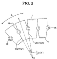
- the connecting pins 14 and the connecting holes 15 of the inner link 1 are rotatably fitted with the pin holes 15 and the connecting pins 14, respectively, of two inner links 1 that are disposed on front and rear sides of the inner link 1, as shown in FIG. 2.
- the front and rear ends 12 and 13 of the inner link 1 each have an upper end face portion 121, 131 and a lower end face portion 122, 132 extending upward and downward, respectively, from a vertical central portion of the corresponding end 12, 13.
- the upper front and rear end face portions 121, 131 extend parallel with each other, while the lower front and rear end face portions 122, 132 extend convergently with each other.
- FIG. 2 when a cable drag chain having plural interconnected inner links 1 is bent about a center O, the lower front and rear end face portions 122, 132 of adjacent two inner links 1, 1 abut with each other so that the maximum bending angle of the cable drag chain is limited to an angle ⁇ .
- the lower front and rear end face portions 122, 133 each extend obliquely at an angle Y ( ⁇ /2) with respect to a vertical centerline of the inner link 1.
- the upper front and rear end face portions 121, 131 of each inner link 1 come into abutment with upper rear and front end face portions 131, 121 of the adjacent inner links 1 so as to prevent the cable drag chain from bending reversely into a downwardly projecting U-shape.
- the lower end face portions 122, 132 of the molded inner link 1 have a certain width.
- the lower end face portion 122 (132) of each inner link 1 comes into abutment with the lower end face portion 132 (122) of the adjacent inner link 1 over the entire area thereof to thereby prevent further bending of the cable drag chain.
- flexible members such as electric cables and hydraulic or pneumatic hoses, held in the cable drag chain can be protected safely against damage.
- the lower end face portions 122, 132 of the inner link 1 form stopper surfaces.
- plural inner links 1 connected end to end form an elongated framework of the cable drag chain.
- Each of the inner links 1 is pivotally movable relative to the adjacent inner link 1 between an upright position in which the respective central axes of the adjacent two inner links 1, 1 extend straight, and a tilted position in which the adjacent inner two links 1, 1 are tilted with each other at an angle of ⁇ .
- a space B is formed between the adjacent two inner links 1, 1.
- an outer link 2 (FIG. 3) is used.
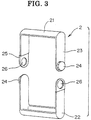
- the outer link 2 is composed of a pair of generally U-shaped upper and lower outer link members 21 and 22 having a width larger than a maximum width of the space B.
- Each of the U-shaped outer link members 21, 22 has an outwardly projecting connecting pin 24 formed at one end and thereof and a pin hole 26 formed at the opposite end thereof for snugly receiving therein the connecting pin 24 of the other outer link member 22, 21.
- the end including the pin hole 26 is offset outward from the plane of one leg of the U-shaped outer link member 21, 22 by a distance equal to the thickness of the outer link member 21, 22.
- the upper and lower outer link members 21, 22 are identical in shape and configuration so as to reduce the number of parts used to form a complete cable drag chain.
- the U-shaped upper and lower outer link members 21, 22 are held in vertical disposition with their open ends facing each other, and the connecting pin 24 and pin hole 26 of the upper outer link member 21 are fitted with the pin hole 26 and connecting pin 24 of the lower outer link member 22.
- the upper and lower outer link members 21, 22 are detachably connected with each other to form a single outer link 2.
- plural outer links 2 are mounted on the framework such that a joint portion between adjacent two inner links 1 is covered by one outer link 2.
- a cable drag chain is thus produced.
- the framework (formed by interconnected inner links 1) of the cable drag chain is connected at one end to a fixed portion C of a machine tool, for example, and at the other end to a movable member D, such as a tool slide, of the machine tool, as shown in FIG. 4.
- a space B formed between adjacent two inner links 1, 1 at a bent or curved portion of the cable drag chain is closed by the outer link 2 fitted around the outer periphery of a joint portion between the adjacent two inner links 1, 1.
- the cable drag chain Since a framework of the cable drag chain is formed by a plurality of interconnected hollow rectangular molded inner links 1, the cable drag chain as a whole has a high torsional rigidity.
- the end face portions of adjacent two inner lings come in abutment with each other over the entire area thereof to thereby limit the radius of curvature of a bent or curved portion while restricting the angle of bend in the opposite direction (no-back-bend direction), the cable drag chain is highly rigid and resistant against damage even when subjected to an external force.
- the face-to-face contact between the opposed end face portions of the adjacent two inner links 1 can achieve accurate restriction of angular movement between the adjacent inner links 1, the flexible members received inside the cable drag chain are completely free from undue bending.
- the cable drag chain as a whole is light in weight, can be manufactured at a relatively low cost, produces little amount of plastic powder due to abrasive wear of the links 1, 2, and is able to reduce a noise produced when the inner and outer links collide with each other during movement of the cable drag chain.
- the inner links 1 molded of synthetic resin By using the inner links 1 molded of synthetic resin, it is possible to reduce a noise produced when the cable drag chain beats the floor surface on which the machine tool is installed. Additional noise reducing effect can be obtained by using the outer links 2 molded of synthetic resin.
- connection between the adjacent inner links 1, 1 and the connection between the upper and lower outer link members 21, 33 are both achieved by fitting engagement between the connecting pins 14, 24 and the pin holes 15, 26.
- Such pin and pin-hole connection can be assembled and disassembled with utmost ease. Since the upper and lower outer link members 21, 22 are identical in shape and configuration, the number of parts used to form the cable drag chain is reduced.
- FIG. 5A to 5C show a inner link 3 used in a cable drag chain according to a second embodiment of the present invention.
- the inner link 3 is composed of a hollow rectangular ring-like member 31 molded of synthetic resin and has a certain thickness.
- the ring-like inner link 3 has a front end 32 and a rear end 33.
- a pair of connecting pins 34 is formed in diametrically opposite relation.
- a pair of pin holes 35 is formed in diametrically opposite relation for rotatably receiving the connecting pins 34, respectively, of an adjacent inner link 3.
- a plurality of such inner links 1 are connected end to end, as shown in FIG. 6, so as to form an elongated cable drag chain.
- the front and rear ends 32 and 33 (FIG. 5A) of the inner link 3 each have an upper end face portion 321, 331 and a lower end face portion 322, 332 extending upward and downward, respectively, from a vertical central portion of the corresponding end 32, 33.
- the upper front and rear end face portions 321, 331 extend parallel with each other, while the lower front and rear end face portions 322, 332 extend convergently with each other.
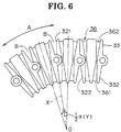
- FIG. 6 when a cable drag chain having plural interconnected inner links 3 is bent about a center O, the lower front and rear end face portions 322, 332 of adjacent two inner links 3, 3 abut with each other so that the maximum bending angle of the cable drag chain is limited to an angle ⁇ .
- the lower front and rear end face portions 122, 133 each extend obliquely at an angle Y ( ⁇ /2) with respect to a vertical centerline of the inner link 3.
- the upper front and rear end face portions 321, 331 of each inner link 3 come into abutment with upper rear and front end face portions 331, 321 of the adjacent inner links 3 so as to prevent the cable drag chain from bending reversely into a downwardly projecting U-shape.
- the lower end face portions 322, 332 of the molded inner link 3 have a certain width.
- the lower end face portion 322 (332) of each inner link 3 comes into abutment with the lower end face portion 332 (322) of the adjacent inner link 3 over the entire area thereof to thereby prevent further bending of the cable drag chain.
- flexible members such as electric cables and hydraulic or pneumatic hoses, can be safely held inside the cable drag chain without damage.
- the lower end face portions 322, 332 of the inner link 3 form stopper surfaces.
- the inner link 3 has two circumferential grooves 36, 36 formed in the outer peripheral surface and spaced in the axil direction of the hollow inner link 3, so that the grooves 36, 36 are located adjacent the front end 32 and the rear end 33, respectively, of the inner link 3.
- Each of the circumferential grooves 36 has a lower groove portion 361 extending along a lower half of the perimeter of the inner link 3, and an upper groove portion 362 extending along an upper half of the perimeter of the inner link 3.
- the lower groove portion 361 takes the form of a triangle
- the upper groove 362 takes the form of an inverted triangle.
- the lower and upper groove portions 361 and 362 are formed in a bottom wall 38 and a top wall 39, respectively, of the inner link 3, so as to allow end flanges 47 (FIG. 7) of an outer link 4 to move relative to adjacent two inner links 3, as will be described later.
- plural inner links 3 are connected end to end to form an elongated framework of the cable drag chain.
- Each of the inner links 3 is pivotally movable relative to the adjacent inner link 3 between an upright position in which the respective central axes of the adjacent two inner links 3, 3 extend straight, and a tilted position in which the adjacent inner two links 3, 3 are tilted with each other at an angle of ⁇ .
- a space B is formed between the adjacent two inner links 3, 3.
- the outer link 4 shown in FIG. 7 is used to close the space B (FIG. 6).
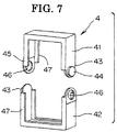
- the outer link 4 is composed of a pair of generally U-shaped upper and lower outer link members 41 and 42 having a width larger than a maximum width of the space B.
- Each of the U-shaped outer link members 41, 42 has an outwardly projecting connecting pin 44 formed at one end 43 and thereof and a pin hole 46 formed at the opposite end 45 thereof for snugly receiving therein the connecting pin 44 of the other outer link member 42, 41.
- the end 45 including the pin hole 46 is offset outward from the plane of one leg of the U-shaped outer link member 41, 42 by a distance equal to the thickness of the outer link member 41, 42.
- the upper and lower outer link members 41, 42 are identical in shape and configuration so that the number of parts used to form a complete cable drag chain can be reduced.
- the U-shaped upper and lower outer link members 41, 42 are held in vertical disposition with their open ends facing each other, and the connecting pin 44 and pin hole 46 of the upper outer link member 41 are fitted with the pin hole 46 and connecting pin 44 of the lower outer link member 22.
- the upper and lower outer link members 41, 42 are detachably connected with each other to form a single outer link 4.
- Each of the outer link members 41, 42 has a pair of end flanges 47, 47 extending along the front and rear edges thereof.
- the end flanges 47 project in a radial inward direction of the outer link member 41, 42.
- the end flanges 47 of the respective link members 4, 42 form a pair of annular end flanges 47 formed at the front and rear ends, respectively, of the outer link 4.
- the annular end flanges 47 are received in adjacent two circumferential grooves 36, 36 of each pair of adjacent inner links 3, 3.
- the annular end flanges 47 serve also as a stopper to prevent relative pivotal movement between the upper and lower outer link members 41, 42 while the link members 41, 42 are in the assembled state.
- plural outer links 4 are mounted on the framework so that a joint portion between adjacent two inner links 3 is covered by one outer link 4.
- a cable drag chain is thus produced.
- the framework (formed by interconnected inner links 3) of the cable drag chain is connected at one end to a fixed portion C of a machine tool, for example, and at the other end to a movable member D, such as a tool slide, of the machine tool, as shown in FIG. 8.
- a space B (FIG. 6) formed between adjacent two inner links 3, 3 at a bent or curved portion of the cable drag chain is closed by the outer link 4 fitted around the outer periphery of a joint portion between the adjacent two inner links 3, 3.
- the synthetic resin material forming the outer link 4 is greater in flexibility of the synthetic resin material forming the inner link 3.
- the width b of the outer link 4 in the longitudinal direction of the cable drag chain i.e., the outside distance between the front and rear end flanges 47 of the outer link 4
- the width b of the outer link 4 in the longitudinal direction of the cable drag chain is more than twice as large as a combined width a of the groove 362 (361) and an adjacent end edge portion 371 of the inner link 3 (i.e., the distance between inner sidewalls 372, 372 of adjacent two grooves 362, 372 with which the end flanges 47, 47 of the outer link 4 engage).
- the outside distance b between the front and rear end flanges 47 of the outer link 4 is slightly greater than the distance ( a x 2) between inner sidewalls 372 of the adjacent grooves 362 (361) with which the front and rear end flanges 47 engage ( b >2 a ).
- the cable drag chain of the second embodiment is advantageous over the cable drag chain of the first embodiment shown in FIGS. 1-4 in that by virtue of the engagement between the end flanges 47 of the outer link 4 and the grooves 36 of two adjacent inner links 3, the outer link 4 is held in position against removal from the inner links 3 even when the individual inner links 3 moves relative to one another.
- the internal space formed in the cable drag chain is always closed and concealed from the view. This arrangement ensures that dust produced inside the cable drag chain is held inside the cable drag chain against leakage.
- FIG. 10 shows a modified form of the outer link according to the present invention.
- the outer link 5 has a hinge portion 52 at one side 51 so that the outer link 5 can be opened and closed about the hinge 52.
- a connecting pin 54 is formed at one of two mating open ends of the outer link 5, and a pin holes 55 is formed in the other open end of the outer link 5 for receiving therein the connecting pin 54.
- the connecting pin 54 and the pin hole 55 are fitted together at the opposite side 53 of the outer link 5.
- the outer link 5 has an annular flange 56 at each of the front and rear ends thereof.
- the outer link 5 is mounted on a framework formed by interconnected inner links (not shown but identical to one shown in FIG. 6) so as to cover or surround a joint portion formed between adjacent two inner links. Though not shown, the end flanges 56 of the outer link 5 are received in adjacent grooves of each pair of adjacent inner links in the same manner as the end flanges 47 shown in FIGS. 9B.
- the hinged one-piece outer link 5 further reduces the number of parts of the cable drag chain and can be easily mounted to a joint portion of the inner links 3 as compared to the two-piece pin-connected outer links 2, 4.
- Other operational features of the outer link 5 are the same as those described above with respect to the outer link 4 shown in FIG. 7.
Landscapes
- Engineering & Computer Science (AREA)
- General Engineering & Computer Science (AREA)
- Mechanical Engineering (AREA)
- Electric Cable Arrangement Between Relatively Moving Parts (AREA)
- Details Of Connecting Devices For Male And Female Coupling (AREA)
- Details Of Indoor Wiring (AREA)
Abstract
Description
- The present invention relates to a cable drag chain for supporting and guiding such flexible members as electric cables and hydraulic or pneumatic hoses between a fixed portion and a movable portion of a machine tool, an earth-moving machine, a conveyor and so on.
- Cable drag chains have been proposed to support and guide flexible members, such as electric cables and hydraulic or pneumatic hoses, while protecting the flexible members against damage or entanglement which may occur due to undue twisting or stretching of the flexible members during movement of the movable part of a machine tool, earth-moving machine or conveyor to which the flexible members are connected.
- One example of such conventional cable drag chains is disclosed in Japanese Patent Publication No. SHO-62-15008, entitled "Energy Conduit Support". The disclosed energy conduit support includes inner tubular members made from synthetic resin and outer tubular members made of metal and arranged alternately with the inner tubular members in the longitudinal direction of the energy conduit support. Each of the inner tubular members has two sector-like grooves formed at the outer periphery on each of two opposite side of the inner tubular member. Each of the outer tubular members is composed of a pair of upper and outer tubular member halves connected together by pins so that the pin-connected tubular member halves surround opposed end portions of two adjacent inner tubular members. The joint between the inner and outer tubular members in the longitudinal direction of the energy conduit support is formed by way of fitting engagement between the sector-like grooves of the inner tubular member and stopper projections formed on the respective inner peripheries of the outer tubular member halves.
- In the energy conduit support shown in the Japanese publication specified above, since the inner tubular members are not connected together by themselves, a framework of the energy conduit support is constituted by the outer tubular member halves pined together to form an outer tubular member. Due to this construction, the conventional energy conduit support as a whole has a relatively low torsional rigidity. In addition, since the bending angle of the energy conduit support is limited by abutting engagement between the grooves of the inner tubular members and the stopper projections of the outer tubular members, the energy conduit support is likely to be damaged when subjected to a relatively large force.
- When pins are removed, the outer tubular member halves and the adjacent inner tubular members are disconnected from one another, thus forming a break or interruption in the energy conduit support. Reassembling of the inner and outer tubular members to mend the break is uneasy to achieve. In addition, once the outer tubular member halves and the inner tubular members are assembled together, disassembling work of these components is tedious and time-consuming. When the disassembled components are to be assembled again, the pins must be replaced with new ones. This replacement increases the cost of the energy conduit support and makes the energy conduit support unsuitable for an application in which a frequent maintenance and inspection is a major requirement.
- Furthermore, the inner tubular members made from synthetic resin are susceptible to abrasive wear and produce plastic powder due to friction contact with the outer tubular member halves made of metal during use of the energy conduit support. Use of the metallic material increases the overall weight of the energy conduit support and produces a great noise when the metallic outer tubular members abut on the adjacent plastic inner tubular member or beat the floor surface during use of the energy conduit support.
- With the foregoing problems in view, it is an object of the present invention to provide a cable drag chain which has relatively large bending and torsional rigidities and hence can hold flexible members safely against undue bending or twisting, is light in weight, can be manufactured at a relatively low cost, produces little abrasive powder, is easy to assemble and maintain and produces little noise during use.
- According to the present invention, there is provided a cable drag chain comprising a plurality of ring-like inner links pivotally connected together end to end. Each of the inner links has a pair of connecting pins formed at one end thereof, a pair of pin holes formed at the opposite end thereof for receiving the connecting pins of an adjacent one of the inner links to thereby connect two adjacent ones of the inner links, and end faces formed at the front and rear ends of the inner link and serving as stopper surfaces engagable with the stopper surfaces of the adjacent inner links to limit the angle of pivotal movement between the adjacent inner links. The cable drag chain further includes a plurality of outer links, each outer link being detachably mounted to a joint portion between two adjacent one of the inner links and surrounding the joint portion so as to close a space formed between the two adjacent inner links.
- In one preferred form of the present invention, the inner link has two circumferential grooves spaced in an axial direction of the inner link, and the outer link has a pair of annular end flanges formed at opposite ends thereof. The end flanges being received in adjacent two circumferential grooves of each pair of adjacent inner links. The hollow interior space formed in the cable drag chain is fully closed so that dust produced inside the cable drag chain is held within the closed hollow interior space without leakage.
- It is preferable that when the stopper surfaces of two adjacent inner links are in contact with each other, the outside distance between the end flanges of the outer link is larger than the distance between opposed sidewalls of the adjacent two circumferential grooves with which the end flanges are engaged. By virtue of the dimensional difference, the end flanges engage the sidewalls of the circumferential grooves in advance to the abutment between the stopper surfaces of two adjacent inner links, thereby lessening a collision sound of the cable drag chain. To enhance the noise reducing effect, a synthetic resin forming the outer link is more flexible than a synthetic resin forming the inner link.
- It is preferable that the inner link is molded of a synthetic resin, and the outer link is molded of a synthetic resin.
- In one preferred form of the present invention, the outer link is composed of a pair of outer link members of an identical shape and configuration detachably connected at opposite ends, one end of each outer link member has a connecting pin, and the other end of each link member has a pin hole for receiving therein the connecting pin.
- In another preferred form of the present invention, the outer link is comprised of a hinged one-piece outer link having a hinge portion at one side thereof and a pin and pin-hole connection at the other side of thereof.
- Certain preferred embodiments of the present invention will now be described in detail, by way of example only, with reference to the accompanying drawings, in which:
- FIG. 1 is a perspective view of an inner link of a cable drag chain according to a first embodiment of the present invention;
- FIG. 2 is a side view showing plural inner links connected end to end;
- FIG. 3 is an exploded perspective view of an outer link of the cable drag chain;
- FIG. 4 is a side view showing an assembled condition of the cable drag chain according to the first embodiment of the present invention;
- FIG. 5A is a perspective view of an inner link of a cable drag chain according to a second embodiment of the present invention;
- FIG. 5B is a side view of the inner link shown in FIG. 5A;
- FIG. 5C is a front elevational view of the inner link shown in FIG. 5A;
- FIG. 6 is a side view showing plural inner links shown in FIGS. 5A-5C;
- FIG. 7 is an exploded perspective view of an outer link of the cable drag chain according to the second embodiment;
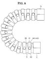
- FIG. 8 is a side view showing an assembled condition of the cable drag chain according to the second embodiment of the present invention;
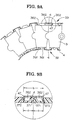
- FIG. 9A is a cross-sectional view of the cable drag chain shown in FIG. 8;
- FIG. 9B is an enlarged view of a portion of FIG. 9A; and
- FIG. 10 is a perspective view of an outer link according to a modification of the present invention.
-
- The following description is merely exemplary in nature and is in no way intended to limit the invention or its application or uses.
- Referring now to the drawings and FIG. 1 in particular, there is shown in perspective view an
inner link 1 of a cable drag chain according to a first embodiment of the present invention. Theinner link 1 is comprised of a hollow, rectangular ring-like member 11 molded of a synthetic resin. The hollow ring-like inner link 1 (11) has a pair of connectingpins 14 formed in diametrically opposite relation at the center of a front end 12 (left end in FIG. 1) thereof, and a pair of diametricallyopposite pin holes 15 formed in diametrically opposite relation at the center of a rear end 13 (left end in FIG. 1) thereof. The connectingpins 14 and the connectingholes 15 of theinner link 1 are rotatably fitted with thepin holes 15 and the connectingpins 14, respectively, of twoinner links 1 that are disposed on front and rear sides of theinner link 1, as shown in FIG. 2. - The front and
rear ends inner link 1 each have an upperend face portion end face portion corresponding end end face portions end face portions inner links 1 is bent about a center O, the lower front and rearend face portions inner links end face portions 122, 133 each extend obliquely at an angle Y (α/2) with respect to a vertical centerline of theinner link 1. The upper front and rearend face portions inner link 1 come into abutment with upper rear and frontend face portions inner links 1 so as to prevent the cable drag chain from bending reversely into a downwardly projecting U-shape. - Since the
inner link 1 is molded of synthetic resin, the lowerend face portions inner link 1 have a certain width. When the cable drag chain is caused to bend, the lower end face portion 122 (132) of eachinner link 1 comes into abutment with the lower end face portion 132 (122) of the adjacentinner link 1 over the entire area thereof to thereby prevent further bending of the cable drag chain. By thus limiting the bending angle of the cable drag chain, flexible members, such as electric cables and hydraulic or pneumatic hoses, held in the cable drag chain can be protected safely against damage. The lowerend face portions inner link 1 form stopper surfaces. - As shown in FIG. 2, plural
inner links 1 connected end to end form an elongated framework of the cable drag chain. Each of theinner links 1 is pivotally movable relative to the adjacentinner link 1 between an upright position in which the respective central axes of the adjacent twoinner links links inner links - In order to close the space B, an outer link 2 (FIG. 3) is used. As shown in FIG. 3, the
outer link 2 is composed of a pair of generally U-shaped upper and lowerouter link members outer link members pin 24 formed at one end and thereof and apin hole 26 formed at the opposite end thereof for snugly receiving therein the connectingpin 24 of the otherouter link member pin hole 26 is offset outward from the plane of one leg of the U-shapedouter link member outer link member outer link members outer link members pin 24 andpin hole 26 of the upperouter link member 21 are fitted with thepin hole 26 and connectingpin 24 of the lowerouter link member 22. Thus, the upper and lowerouter link members outer link 2. - After plural
inner links 1 are connected end to end to form an elongated framework, pluralouter links 2 are mounted on the framework such that a joint portion between adjacent twoinner links 1 is covered by oneouter link 2. A cable drag chain is thus produced. In use, the framework (formed by interconnected inner links 1) of the cable drag chain is connected at one end to a fixed portion C of a machine tool, for example, and at the other end to a movable member D, such as a tool slide, of the machine tool, as shown in FIG. 4. In the cable drag chain, a space B formed between adjacent twoinner links outer link 2 fitted around the outer periphery of a joint portion between the adjacent twoinner links outer links - Since a framework of the cable drag chain is formed by a plurality of interconnected hollow rectangular molded
inner links 1, the cable drag chain as a whole has a high torsional rigidity. When the cable drag chain is bent or curved in one direction, the end face portions of adjacent two inner lings come in abutment with each other over the entire area thereof to thereby limit the radius of curvature of a bent or curved portion while restricting the angle of bend in the opposite direction (no-back-bend direction), the cable drag chain is highly rigid and resistant against damage even when subjected to an external force. Additionally, since the face-to-face contact between the opposed end face portions of the adjacent twoinner links 1 can achieve accurate restriction of angular movement between the adjacentinner links 1, the flexible members received inside the cable drag chain are completely free from undue bending. - Furthermore, by the
outer link 2 fitted around the outer periphery of a joint portion between adjacent two inner links, a space B formed at the joint portion when the cable drag chain is bent is closed by theouter link 2. Thus, the hollow interior space of the cable drag chain is fully closed. This arrangement is advantageous because dust produced inside the cable drag chain can be held within the closed hollow interior space of the inside the cable drag chain against leakage. Additionally, since theouter links 2 have no function to join or connect the adjacentinner links 1, nor to limit the bending angle of the cable drag chain, it is possible to reduce the thickness and weight of theouter links 2, leading to a reduction of the manufacturing cost of theouter links 2. - Because all of the parts (i.e, the inner and
outer links 1 and 2) of the cable drag chain are molded of synthetic resin, the cable drag chain as a whole is light in weight, can be manufactured at a relatively low cost, produces little amount of plastic powder due to abrasive wear of thelinks - By using the
inner links 1 molded of synthetic resin, it is possible to reduce a noise produced when the cable drag chain beats the floor surface on which the machine tool is installed. Additional noise reducing effect can be obtained by using theouter links 2 molded of synthetic resin. - The connection between the adjacent
inner links outer link members pins outer link members - FIG. 5A to 5C show a
inner link 3 used in a cable drag chain according to a second embodiment of the present invention. Theinner link 3 is composed of a hollow rectangular ring-like member 31 molded of synthetic resin and has a certain thickness. The ring-likeinner link 3 has afront end 32 and arear end 33. At a central portion of thefront end 32, a pair of connectingpins 34 is formed in diametrically opposite relation. Similarly, at a central portion of therear end 23, a pair of pin holes 35 is formed in diametrically opposite relation for rotatably receiving the connectingpins 34, respectively, of an adjacentinner link 3. By way of the pin and pin-hole connection, a plurality of suchinner links 1 are connected end to end, as shown in FIG. 6, so as to form an elongated cable drag chain. - The front and
rear ends 32 and 33 (FIG. 5A) of theinner link 3 each have an upperend face portion end face portion corresponding end end face portions end face portions inner links 3 is bent about a center O, the lower front and rearend face portions inner links end face portions 122, 133 each extend obliquely at an angle Y (α/2) with respect to a vertical centerline of theinner link 3. The upper front and rearend face portions inner link 3 come into abutment with upper rear and frontend face portions inner links 3 so as to prevent the cable drag chain from bending reversely into a downwardly projecting U-shape. - The lower
end face portions inner link 3 have a certain width. When the cable drag chain is caused to bend, the lower end face portion 322 (332) of eachinner link 3 comes into abutment with the lower end face portion 332 (322) of the adjacentinner link 3 over the entire area thereof to thereby prevent further bending of the cable drag chain. By thus limiting the bending angle of the cable drag chain, flexible members, such as electric cables and hydraulic or pneumatic hoses, can be safely held inside the cable drag chain without damage. The lowerend face portions inner link 3 form stopper surfaces. - As shown in FIG. 5A, the
inner link 3 has twocircumferential grooves inner link 3, so that thegrooves front end 32 and therear end 33, respectively, of theinner link 3. Each of thecircumferential grooves 36 has alower groove portion 361 extending along a lower half of the perimeter of theinner link 3, and anupper groove portion 362 extending along an upper half of the perimeter of theinner link 3. At each of twoopposite side walls 37 of theinner link 3, thelower groove portion 361 takes the form of a triangle, while theupper groove 362 takes the form of an inverted triangle. As best shown in FIGS. 9A and 9B, the lower andupper groove portions bottom wall 38 and atop wall 39, respectively, of theinner link 3, so as to allow end flanges 47 (FIG. 7) of anouter link 4 to move relative to adjacent twoinner links 3, as will be described later. - As shown in FIG. 6, plural
inner links 3 are connected end to end to form an elongated framework of the cable drag chain. Each of theinner links 3 is pivotally movable relative to the adjacentinner link 3 between an upright position in which the respective central axes of the adjacent twoinner links links inner links - The
outer link 4 shown in FIG. 7 is used to close the space B (FIG. 6). As shown in this figure, theouter link 4 is composed of a pair of generally U-shaped upper and lowerouter link members outer link members pin 44 formed at oneend 43 and thereof and apin hole 46 formed at theopposite end 45 thereof for snugly receiving therein the connectingpin 44 of the otherouter link member end 45 including thepin hole 46 is offset outward from the plane of one leg of the U-shapedouter link member outer link member outer link members outer link members pin 44 andpin hole 46 of the upperouter link member 41 are fitted with thepin hole 46 and connectingpin 44 of the lowerouter link member 22. Thus, the upper and lowerouter link members outer link 4. - Each of the
outer link members end flanges outer link member outer link members end flanges 47 of therespective link members annular end flanges 47 formed at the front and rear ends, respectively, of theouter link 4. Theannular end flanges 47 are received in adjacent twocircumferential grooves inner links annular end flanges 47 serve also as a stopper to prevent relative pivotal movement between the upper and lowerouter link members link members - After plural
inner links 3 are connected end to end to form an elongated framework, pluralouter links 4 are mounted on the framework so that a joint portion between adjacent twoinner links 3 is covered by oneouter link 4. A cable drag chain is thus produced. In use, the framework (formed by interconnected inner links 3) of the cable drag chain is connected at one end to a fixed portion C of a machine tool, for example, and at the other end to a movable member D, such as a tool slide, of the machine tool, as shown in FIG. 8. In the cable drag chain, a space B (FIG. 6) formed between adjacent twoinner links outer link 4 fitted around the outer periphery of a joint portion between the adjacent twoinner links annular end flanges 47 of theouter link 4 are engaged in two adjacentcircumferential grooves 36 in each pair of adjacentinner links outer links - It is preferable that the synthetic resin material forming the
outer link 4 is greater in flexibility of the synthetic resin material forming theinner link 3. As shown in FIG. 9B, the width b of theouter link 4 in the longitudinal direction of the cable drag chain (i.e., the outside distance between the front andrear end flanges 47 of the outer link 4) is more than twice as large as a combined width a of the groove 362 (361) and an adjacent end edge portion 371 of the inner link 3 (i.e., the distance betweeninner sidewalls grooves end flanges outer link 4 engage). - In other words, when the stopper surfaces at the front and rear ends of adjacent two
inner links rear end flanges 47 of theouter link 4 is slightly greater than the distance (a x 2) betweeninner sidewalls 372 of the adjacent grooves 362 (361) with which the front andrear end flanges 47 engage (b>2a). - The cable drag chain of the second embodiment is advantageous over the cable drag chain of the first embodiment shown in FIGS. 1-4 in that by virtue of the engagement between the
end flanges 47 of theouter link 4 and thegrooves 36 of two adjacentinner links 3, theouter link 4 is held in position against removal from theinner links 3 even when the individualinner links 3 moves relative to one another. The internal space formed in the cable drag chain is always closed and concealed from the view. This arrangement ensures that dust produced inside the cable drag chain is held inside the cable drag chain against leakage. - In addition, partly because the outside distance b between the front and
rear end flanges 47 of theouter link 4 is slightly larger than the distance (2 x a) betweeninner side walls 372 of theadjacent grooves 36 of each pair of adjacentinner links 3, 3 (b>2a), and partly because the synthetic resin material forming theouter link 4 is more flexible than the synthetic resin material of theinner link 3, when the cable drag chain is caused to bend, theend flanges 47 of theouter link 4 are brought into contact with theinner sidewalls 372 of thegrooves 36 and then deform resiliently before the two adjacentinner links 3 abut with each other. With this resilient deformation of theend flanges 47, a noise produced upon abutment of the adjacentinner links 3 can be reduced. - FIG. 10 shows a modified form of the outer link according to the present invention. The modified
outer link 5, as opposed to theouter links outer link 5 has ahinge portion 52 at oneside 51 so that theouter link 5 can be opened and closed about thehinge 52. To keep theouter link 5 in a closed position, a connectingpin 54 is formed at one of two mating open ends of theouter link 5, and a pin holes 55 is formed in the other open end of theouter link 5 for receiving therein the connectingpin 54. The connectingpin 54 and thepin hole 55 are fitted together at theopposite side 53 of theouter link 5. Theouter link 5 has anannular flange 56 at each of the front and rear ends thereof. - The
outer link 5 is mounted on a framework formed by interconnected inner links (not shown but identical to one shown in FIG. 6) so as to cover or surround a joint portion formed between adjacent two inner links. Though not shown, theend flanges 56 of theouter link 5 are received in adjacent grooves of each pair of adjacent inner links in the same manner as theend flanges 47 shown in FIGS. 9B. - The hinged one-piece
outer link 5 further reduces the number of parts of the cable drag chain and can be easily mounted to a joint portion of theinner links 3 as compared to the two-piece pin-connectedouter links outer link 5 are the same as those described above with respect to theouter link 4 shown in FIG. 7.
Claims (7)
- A cable drag chain comprising:a plurality of ring-like inner links (1; 3) pivotally connected together end to end, each of the inner links having a pair of connecting pins (14; 34) formed at one end (12; 32) thereof, a pair of pin holes (15; 35) formed at the opposite end (13; 33) thereof for receiving the connecting pins of an adjacent one of the inner links to thereby connect two adjacent inner links, and end faces (121, 131, 122, 132; 321, 331, 322, 332) formed at the front and rear ends of the inner link and serving as stopper surfaces engagable with the stopper surfaces of the adjacent inner links to limit the angle of pivotal movement between the adjacent inner links; anda plurality of outer links (2; 4; 5), each outer link being detachably mounted to a joint portion between two adjacent one of the inner links, the outer link surrounding the joint portion so as to close a space (B) formed between the two adjacent inner links.
- The cable drag chain according to claim 1, wherein the inner link (3) has two circumferential grooves (36) spaced in an axial direction of the inner link, and the outer link (4; 5) has a pair of annular end flanges (47; 56) formed at opposite ends thereof and received in adjacent two circumferential grooves of each pair of adjacent inner links.
- The cable drag chain according to claim 2, wherein when the stopper surfaces of two adjacent inner links are in contact with each other, the outside distance (b) between the end flanges (47; 56) of the outer link (4; 5) is larger than the distance (2 x a) between opposed sidewalls (372, 372) of the adjacent two circumferential grooves (36, 36) with which the end flanges are engaged.
- The cable drag chain according to one of claims 1 to 3, wherein the inner link (3) is molded of a synthetic resin, and the outer link (4, 5) is molded of a synthetic resin, the synthetic resin forming the outer link being more flexible than the synthetic resin forming the inner link.
- The cable drag chain according to one of claims 1 to 4, wherein the inner link (1; 3) is molded of a synthetic resin, and the outer link (2; 4; 5) is molded of a synthetic resin.
- The cable drag chain according to one of claims 1 to 5, wherein the outer link (2; 4) is composed of a pair of outer link members of an identical shape and configuration detachably connected at opposite ends, one end of each outer link member has a connecting pin (24; 44), and the other end of each link member has a pin hole (26; 46) for receiving therein the connecting pin.
- The cable drag chain according to one of claims 1 to 6, wherein the outer link (5) is comprised of a hinged one-piece outer link having a hinge portion (52) at one side thereof and a pin and pin-hole connection at the other side of thereof.
Applications Claiming Priority (2)
| Application Number | Priority Date | Filing Date | Title |
|---|---|---|---|
| JP2000278471A JP3356758B2 (en) | 2000-09-13 | 2000-09-13 | Cable drag chain |
| JP2000278471 | 2000-09-13 |
Publications (3)
| Publication Number | Publication Date |
|---|---|
| EP1188953A2 true EP1188953A2 (en) | 2002-03-20 |
| EP1188953A3 EP1188953A3 (en) | 2002-04-03 |
| EP1188953B1 EP1188953B1 (en) | 2005-06-29 |
Family
ID=18763634
Family Applications (1)
| Application Number | Title | Priority Date | Filing Date |
|---|---|---|---|
| EP01122049A Expired - Lifetime EP1188953B1 (en) | 2000-09-13 | 2001-09-13 | Cable drag chain |
Country Status (8)
| Country | Link |
|---|---|
| US (1) | US6510682B2 (en) |
| EP (1) | EP1188953B1 (en) |
| JP (1) | JP3356758B2 (en) |
| KR (1) | KR100447679B1 (en) |
| CN (1) | CN1216244C (en) |
| DE (1) | DE60111702T2 (en) |
| HK (1) | HK1045363B (en) |
| TW (1) | TW559646B (en) |
Cited By (2)
| Publication number | Priority date | Publication date | Assignee | Title |
|---|---|---|---|---|
| DE10333788B4 (en) * | 2002-08-07 | 2005-10-27 | Yazaki Corp. | The harness sheathing part and the harness arranging structure using the harness sheathing part |
| EP3560050A1 (en) * | 2017-08-22 | 2019-10-30 | Häwa GmbH | Machine frame having a switch cabinet |
Families Citing this family (25)
| Publication number | Priority date | Publication date | Assignee | Title |
|---|---|---|---|---|
| JP3349148B1 (en) | 2001-12-11 | 2002-11-20 | 株式会社椿本チエイン | Closed cable drag chain |
| JP3722477B2 (en) * | 2002-04-02 | 2005-11-30 | 株式会社椿本チエイン | Cable protection guide |
| US7082720B2 (en) * | 2002-06-25 | 2006-08-01 | Sumitomo Wiring Systems, Ltd. | Cable guide and power supply apparatus for a vehicle slide door |
| JP3717071B2 (en) * | 2002-11-05 | 2005-11-16 | 株式会社椿本チエイン | Sealed cable drag chain |
| RU2249551C2 (en) * | 2003-06-26 | 2005-04-10 | Открытое акционерное общество "Северсталь" | Conveyor chain |
| JP4136905B2 (en) * | 2003-11-13 | 2008-08-20 | 株式会社椿本チエイン | Horizontally installed cable protection guide device |
| JP4336602B2 (en) * | 2004-03-29 | 2009-09-30 | 津田駒工業株式会社 | Inclined rotary table for machine tools |
| DE202004005800U1 (en) * | 2004-04-08 | 2005-08-25 | Igus Gmbh | Power supply chain |
| JP3897352B2 (en) | 2004-04-30 | 2007-03-22 | 株式会社椿本チエイン | Cable protection guide device |
| IL164260A0 (en) * | 2004-09-23 | 2005-12-18 | Medigus Ltd | An improved articulation section |
| JP4376822B2 (en) * | 2005-04-22 | 2009-12-02 | 川崎重工業株式会社 | Deformation structure and cable support device |
| JP5012063B2 (en) * | 2007-02-05 | 2012-08-29 | 住友電装株式会社 | Wiring harness wiring structure for automobile |
| DE202009005650U1 (en) * | 2009-04-17 | 2009-07-02 | Igus Gmbh | Power supply chain |
| CN102460871B (en) * | 2009-06-26 | 2015-01-28 | 皇家飞利浦电子股份有限公司 | A guidance chain for guiding cables or other lines in a medical diagnostic apparatus |
| KR200458228Y1 (en) * | 2009-07-08 | 2012-01-30 | 이창인 | Fruit protective wrap using cotton fabric |
| JP5709833B2 (en) * | 2012-12-28 | 2015-04-30 | 株式会社椿本チエイン | Cable protection guide device |
| KR101716490B1 (en) * | 2014-12-19 | 2017-03-14 | 동명대학교산학협력단 | Condo flex cable chain with pin-connection type |
| DE202015100472U1 (en) * | 2015-02-02 | 2015-02-10 | Igus Gmbh | Chain link and circular chain with chain link |
| US9797205B2 (en) | 2015-03-09 | 2017-10-24 | Halliburton Energy Services, Inc. | Collapsible wiring conduit for downhole linear actuator |
| KR102159813B1 (en) * | 2018-12-27 | 2020-09-24 | 재단법인대구경북과학기술원 | Compliant joint |
| CN110081239B (en) * | 2019-04-28 | 2020-08-07 | 洛阳恒基石化科技有限公司 | Tensile hose for oil tank drainage system |
| US20210023400A1 (en) * | 2019-07-22 | 2021-01-28 | Ramil Ravilyevich Musakaev | Seat for safety harness |
| CN110356778B (en) * | 2019-08-19 | 2024-04-26 | 江苏冠超物流科技有限公司 | Chain assembly and telescopic machine |
| CN111188873A (en) * | 2020-02-28 | 2020-05-22 | 深圳市华南天城机床配件有限公司 | Drag chain |
| CN114017471A (en) * | 2021-10-29 | 2022-02-08 | 广东电网有限责任公司广州供电局 | Cable protection guide |
Citations (1)
| Publication number | Priority date | Publication date | Assignee | Title |
|---|---|---|---|---|
| JPS6215008A (en) | 1985-07-10 | 1987-01-23 | Mitsubishi Heavy Ind Ltd | Automatic stepless regulating helical guide for gear shaper |
Family Cites Families (13)
| Publication number | Priority date | Publication date | Assignee | Title |
|---|---|---|---|---|
| US3779003A (en) * | 1972-09-07 | 1973-12-18 | Measurex Corp | Cable carrier with removable plastic links |
| JPS56159915A (en) * | 1980-04-30 | 1981-12-09 | Kabelschlepp Gmbh | Device for holding energy conductor |
| EP0038952B1 (en) * | 1980-04-30 | 1984-05-16 | Kabelschlepp Gesellschaft mit beschränkter Haftung | Energy line support |
| US4373324A (en) * | 1980-09-02 | 1983-02-15 | Maysteel Corporation | Guide apparatus for flexible elements connected to relatively moving units |
| US4392344A (en) * | 1981-06-30 | 1983-07-12 | Central Safety Equipment Company | Chain-link cable carrier |
| DE3507201C1 (en) * | 1985-03-01 | 1989-06-08 | Kabelschlepp Gmbh, 5900 Siegen | Power line carrier |
| KR900003143Y1 (en) * | 1987-05-30 | 1990-04-14 | 주식회사 금성사 | Control device of AC elevator |
| DE8901955U1 (en) * | 1989-02-18 | 1989-04-06 | Kabelschlepp Gmbh, 5900 Siegen | Energy chain |
| JPH0735151Y2 (en) * | 1991-06-24 | 1995-08-09 | イグスジャパン株式会社 | Cable retainer |
| DE9109422U1 (en) * | 1991-07-30 | 1991-10-02 | Shih, Ta-Feng, Changhua City | Rectangular protective tube for a flexible cable |
| DE9109442U1 (en) | 1991-07-31 | 1991-09-26 | Friedrich, Gerhard, 5778 Meschede | Lid ring for containers with removable lid |
| DE9318441U1 (en) | 1993-12-02 | 1994-02-03 | Shih, Ta-Feng, Chang-Hua | Rectangular protective tube for a flexible cable |
| JP3157491B2 (en) * | 1997-11-28 | 2001-04-16 | 株式会社椿本チエイン | Flexible guide support chain |
-
2000
- 2000-09-13 JP JP2000278471A patent/JP3356758B2/en not_active Expired - Fee Related
-
2001
- 2001-09-07 TW TW090122210A patent/TW559646B/en not_active IP Right Cessation
- 2001-09-12 KR KR10-2001-0056102A patent/KR100447679B1/en not_active Expired - Fee Related
- 2001-09-13 CN CN011384433A patent/CN1216244C/en not_active Expired - Fee Related
- 2001-09-13 EP EP01122049A patent/EP1188953B1/en not_active Expired - Lifetime
- 2001-09-13 DE DE60111702T patent/DE60111702T2/en not_active Expired - Fee Related
- 2001-09-13 US US09/951,474 patent/US6510682B2/en not_active Expired - Fee Related
-
2002
- 2002-09-18 HK HK02106829.2A patent/HK1045363B/en not_active IP Right Cessation
Patent Citations (1)
| Publication number | Priority date | Publication date | Assignee | Title |
|---|---|---|---|---|
| JPS6215008A (en) | 1985-07-10 | 1987-01-23 | Mitsubishi Heavy Ind Ltd | Automatic stepless regulating helical guide for gear shaper |
Cited By (2)
| Publication number | Priority date | Publication date | Assignee | Title |
|---|---|---|---|---|
| DE10333788B4 (en) * | 2002-08-07 | 2005-10-27 | Yazaki Corp. | The harness sheathing part and the harness arranging structure using the harness sheathing part |
| EP3560050A1 (en) * | 2017-08-22 | 2019-10-30 | Häwa GmbH | Machine frame having a switch cabinet |
Also Published As
| Publication number | Publication date |
|---|---|
| KR20020021049A (en) | 2002-03-18 |
| US6510682B2 (en) | 2003-01-28 |
| TW559646B (en) | 2003-11-01 |
| JP3356758B2 (en) | 2002-12-16 |
| CN1216244C (en) | 2005-08-24 |
| HK1045363A1 (en) | 2002-11-22 |
| HK1045363B (en) | 2006-04-13 |
| CN1343850A (en) | 2002-04-10 |
| US20020029555A1 (en) | 2002-03-14 |
| DE60111702D1 (en) | 2005-08-04 |
| JP2002089632A (en) | 2002-03-27 |
| EP1188953A3 (en) | 2002-04-03 |
| DE60111702T2 (en) | 2006-05-04 |
| EP1188953B1 (en) | 2005-06-29 |
| KR100447679B1 (en) | 2004-09-08 |
Similar Documents
| Publication | Publication Date | Title |
|---|---|---|
| US6510682B2 (en) | Cable drag chain | |
| KR101639851B1 (en) | Energy guide chain with deformable joint elements | |
| EP1319865B1 (en) | Closed cable drag chain | |
| US7174702B2 (en) | Cable or the like protection and guide device | |
| US6161373A (en) | Flexible energy conducting guide chain and process for producing same | |
| US6550232B1 (en) | Energy guide chain for guiding lines comprising chain links which can move in three dimensions | |
| KR20040014505A (en) | Energy drag chain | |
| US6725642B2 (en) | Protective guide for flexible elongated article | |
| JP5779708B2 (en) | Energy guide chain | |
| TWI613381B (en) | Energy chain, particularly for clean room applications | |
| TW548382B (en) | Protective guide for cables and the like | |
| KR20170056009A (en) | Line-guiding device, in particular for clean room applications, shell parts and supporting skeleton therefor | |
| JP3666801B2 (en) | Energy guide chain | |
| JP3717071B2 (en) | Sealed cable drag chain | |
| KR102720404B1 (en) | Robochain | |
| CN101511711A (en) | Abrasion-resistant hinge rods in modular plastic conveyor belts | |
| JP4111967B2 (en) | Cable protection guide device | |
| JP3585015B2 (en) | Cable chain | |
| US6978595B2 (en) | Chain links and cable carrier chains containing same | |
| CA2058855C (en) | Non-metallic link and chain | |
| US20040237604A1 (en) | Handcuffs | |
| KR200370351Y1 (en) | A cable bearer | |
| JP3806370B2 (en) | Cable protection guide chain | |
| CN224146952U (en) | Pile up roller chain conveyor | |
| RU2805598C2 (en) | Hybrid guidepath loop for large console areas and, in particular, separator cheek for it |
Legal Events
| Date | Code | Title | Description |
|---|---|---|---|
| PUAI | Public reference made under article 153(3) epc to a published international application that has entered the european phase |
Free format text: ORIGINAL CODE: 0009012 |
|
| PUAL | Search report despatched |
Free format text: ORIGINAL CODE: 0009013 |
|
| AK | Designated contracting states |
Kind code of ref document: A2 Designated state(s): AT BE CH CY DE DK ES FI FR GB GR IE IT LI LU MC NL PT SE TR Kind code of ref document: A2 Designated state(s): DE FR GB IT |
|
| AX | Request for extension of the european patent |
Free format text: AL;LT;LV;MK;RO;SI |
|
| AK | Designated contracting states |
Kind code of ref document: A3 Designated state(s): AT BE CH CY DE DK ES FI FR GB GR IE IT LI LU MC NL PT SE TR |
|
| AX | Request for extension of the european patent |
Free format text: AL;LT;LV;MK;RO;SI |
|
| RIC1 | Information provided on ipc code assigned before grant |
Free format text: 7F 16G 13/16 A, 7H 02G 11/00 B |
|
| 17P | Request for examination filed |
Effective date: 20020516 |
|
| AKX | Designation fees paid |
Free format text: DE FR GB IT |
|
| RAP1 | Party data changed (applicant data changed or rights of an application transferred) |
Owner name: TSUBAKIMOTO CHAIN CO. |
|
| RIN1 | Information on inventor provided before grant (corrected) |
Inventor name: MIZUMOTO, MICHIYO Inventor name: KOMIYA, SHOICHIRO Inventor name: MATSUDA, TAKAYUKI |
|
| 17Q | First examination report despatched |
Effective date: 20040809 |
|
| GRAP | Despatch of communication of intention to grant a patent |
Free format text: ORIGINAL CODE: EPIDOSNIGR1 |
|
| GRAS | Grant fee paid |
Free format text: ORIGINAL CODE: EPIDOSNIGR3 |
|
| GRAA | (expected) grant |
Free format text: ORIGINAL CODE: 0009210 |
|
| AK | Designated contracting states |
Kind code of ref document: B1 Designated state(s): DE FR GB IT |
|
| REG | Reference to a national code |
Ref country code: GB Ref legal event code: FG4D |
|
| RIN1 | Information on inventor provided before grant (corrected) |
Inventor name: KOMIYA, SHOICHIRO Inventor name: MIZUMOTO, MICHIYO Inventor name: MATSUDA, TAKAYUKI |
|
| REF | Corresponds to: |
Ref document number: 60111702 Country of ref document: DE Date of ref document: 20050804 Kind code of ref document: P |
|
| PGFP | Annual fee paid to national office [announced via postgrant information from national office to epo] |
Ref country code: GB Payment date: 20050902 Year of fee payment: 5 |
|
| PGFP | Annual fee paid to national office [announced via postgrant information from national office to epo] |
Ref country code: FR Payment date: 20050928 Year of fee payment: 5 |
|
| ET | Fr: translation filed | ||
| PLBE | No opposition filed within time limit |
Free format text: ORIGINAL CODE: 0009261 |
|
| STAA | Information on the status of an ep patent application or granted ep patent |
Free format text: STATUS: NO OPPOSITION FILED WITHIN TIME LIMIT |
|
| 26N | No opposition filed |
Effective date: 20060330 |
|
| GBPC | Gb: european patent ceased through non-payment of renewal fee |
Effective date: 20060913 |
|
| REG | Reference to a national code |
Ref country code: FR Ref legal event code: ST Effective date: 20070531 |
|
| PG25 | Lapsed in a contracting state [announced via postgrant information from national office to epo] |
Ref country code: GB Free format text: LAPSE BECAUSE OF NON-PAYMENT OF DUE FEES Effective date: 20060913 |
|
| PG25 | Lapsed in a contracting state [announced via postgrant information from national office to epo] |
Ref country code: FR Free format text: LAPSE BECAUSE OF NON-PAYMENT OF DUE FEES Effective date: 20061002 |
|
| PGFP | Annual fee paid to national office [announced via postgrant information from national office to epo] |
Ref country code: DE Payment date: 20080926 Year of fee payment: 8 |
|
| PGFP | Annual fee paid to national office [announced via postgrant information from national office to epo] |
Ref country code: IT Payment date: 20080927 Year of fee payment: 8 |
|
| PG25 | Lapsed in a contracting state [announced via postgrant information from national office to epo] |
Ref country code: DE Free format text: LAPSE BECAUSE OF NON-PAYMENT OF DUE FEES Effective date: 20100401 |
|
| PG25 | Lapsed in a contracting state [announced via postgrant information from national office to epo] |
Ref country code: IT Free format text: LAPSE BECAUSE OF NON-PAYMENT OF DUE FEES Effective date: 20090913 |