EP1188653A2 - A switch guide for a bicycle control panel - Google Patents
A switch guide for a bicycle control panel Download PDFInfo
- Publication number
- EP1188653A2 EP1188653A2 EP01121949A EP01121949A EP1188653A2 EP 1188653 A2 EP1188653 A2 EP 1188653A2 EP 01121949 A EP01121949 A EP 01121949A EP 01121949 A EP01121949 A EP 01121949A EP 1188653 A2 EP1188653 A2 EP 1188653A2
- Authority
- EP
- European Patent Office
- Prior art keywords
- switch
- control panel
- guide
- protrusion
- bicycle
- Prior art date
- Legal status (The legal status is an assumption and is not a legal conclusion. Google has not performed a legal analysis and makes no representation as to the accuracy of the status listed.)
- Granted
Links
Images


Classifications
-
- B—PERFORMING OPERATIONS; TRANSPORTING
- B62—LAND VEHICLES FOR TRAVELLING OTHERWISE THAN ON RAILS
- B62M—RIDER PROPULSION OF WHEELED VEHICLES OR SLEDGES; POWERED PROPULSION OF SLEDGES OR SINGLE-TRACK CYCLES; TRANSMISSIONS SPECIALLY ADAPTED FOR SUCH VEHICLES
- B62M25/00—Actuators for gearing speed-change mechanisms specially adapted for cycles
- B62M25/08—Actuators for gearing speed-change mechanisms specially adapted for cycles with electrical or fluid transmitting systems
-
- B—PERFORMING OPERATIONS; TRANSPORTING
- B62—LAND VEHICLES FOR TRAVELLING OTHERWISE THAN ON RAILS
- B62K—CYCLES; CYCLE FRAMES; CYCLE STEERING DEVICES; RIDER-OPERATED TERMINAL CONTROLS SPECIALLY ADAPTED FOR CYCLES; CYCLE AXLE SUSPENSIONS; CYCLE SIDECARS, FORECARS, OR THE LIKE
- B62K23/00—Rider-operated controls specially adapted for cycles, i.e. means for initiating control operations, e.g. levers, grips
- B62K23/02—Rider-operated controls specially adapted for cycles, i.e. means for initiating control operations, e.g. levers, grips hand actuated
-
- H—ELECTRICITY
- H01—ELECTRIC ELEMENTS
- H01H—ELECTRIC SWITCHES; RELAYS; SELECTORS; EMERGENCY PROTECTIVE DEVICES
- H01H9/00—Details of switching devices, not covered by groups H01H1/00 - H01H7/00
- H01H9/02—Bases, casings, or covers
- H01H9/06—Casing of switch constituted by a handle serving a purpose other than the actuation of the switch, e.g. by the handle of a vacuum cleaner
- H01H2009/068—Casing of switch constituted by a handle serving a purpose other than the actuation of the switch, e.g. by the handle of a vacuum cleaner with switches mounted on a handlebar, e.g. for motorcycles, fork lift trucks, etc.
Definitions
- the present invention relates generally to bicycle control panels, and more particularly to a switch guide located between a pair of switches on a computerized bicycle control panel for guiding a bicycle rider's thumb to a proper switch on the control panel.
- Modern bicycles allow the rider to control the gears, the brakes and other features of the bicycle to optimize the rider's experience.
- Much of the control functions are computerized so that a rider can control the particular function by simply pressing a switch on a control panel.
- a typical computerized control panel includes a base member mounted to the bicycle handlebar and numerous switches on the control panel, each switch corresponding to a particular function that is controllable by the rider.
- the rider may be desirable for the rider to repeatedly manipulate various switches to adapt to the varying road conditions. For instance, if the bicycle ride covers an uphill or downhill terrain, the rider may wish to change the gears to correspond to the incline of the terrain. In this regard, the rider would manipulate a switch that would cause the change in the bicycle gears. It is important to some riders to be able to activate the switch at a precise time corresponding to a particular location or condition in the ride.
- a visual indicator is provided to inform the rider of the function of each switch.
- the present invention overcomes the aforementioned problem by providing a switch guide located between a pair of switches on a computerized tricycle control panel for guiding a bicycle rider's thumb to a proper switch on the control panel.
- the switch guide is preferably a protrusion dimensioned to be detected by the bicycle rider's thumb.
- the Height of the switch guide is greater than the height of the switch for easy detection by the bicycle rider.
- the height of the switch guide is greater than the height of the switch, when the switch is activated.
- the switch guide is a depression located between a pair of switches.
- the depression is dimensioned to be detected by the bicycle rider's thumb.
- the switch guide is located in sufficient proximity to the switches to allow the rider's thumb to access one of the switches by moving the thumb to one side of the switch guide and the other switch by moving the thumb to the other side of the switch guide.
- the switch guide is preferably located exactly in the middle of the region between the first and second switches so that it is equidistant from each switch.
- the rider knows that his thumb is centered between the pair of switches. From the switch guide, the rider can move his or her thumb to one side of the guide to access a first switch and to the other side of the guide to access a second switch. Accordingly, the switch guide allows a rider to accurately and quickly access a desired switch without 11:)oking down at the control panel, in rough and bumpy terrain.
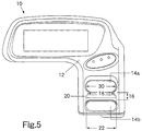
- control panel 10 includes a control panel base 12 and a plurality of switches 14a, 14b located on the control panel base 12.
- switches 14a, 14b are used herein to include buttons, keys, indicators or any other device which, when activated, will initiate an operation, either mechanically or electrically.
- switches 14a and 14b could be shifting switches that change the front or rear gears.
- the switches 14a, 14b preferably extend from the control panel base 10.
- the switches can be soft keys that are aligned with the control panel base 1 2 and do not protrude therefrom.
- the switches 14a, 1 4b are preferably adjacent to each other, defining a region 1 6 there)between.
- a switch guide 20 is provided in the region 16 between a first switch 14a and a second switch 14b.
- the switch guide 20 is completely situated in the region 16 between the first switch 14a and second switch 14b.
- the switch guide 20 has a length 22 that is equal to, or substantially equal to, the length 18 of the region 16 between the first switch 14a and the second switch 14b, such that the switch guide occupies the entire length of the region 16.
- the switch guide 20 preferably protrudes from the control panel base and is dimensioned to be detectable by a human hand.
- the height 24 of the switch guide 20 is greater than the height 26 of the adjacent switches 14a, 14b.
- the height 24 of the switch guide 20 is greater than the height 26 of the adjacent switches 14a, 14b, only when the switch is activated.
- the switch 14b can be activated by pressing thereon. In an activated state, the switch 14b has a shorter height 28 than the height 26 of the switch at its initial rest position, as shown with switch 14a, and in phantom with switch 14b.
- the length 22 of the switch guide 20 is equal to the length 30 of the switch 14a, 14b.
- the switch guide 20 is preferably located equidistant from the first switch 14a and the second witch 14b, in the center of region 16.
- the switch guide 20 is preferably rigid and non-movable, such that a rider will not activate any mechanical or electrical operation by touching the switch guide 20.
- the shape of the switch guide 20 can be ergonomically designed to suit the comfort of the bicycle rider.
- the switch guide is shown as having a dome-shapecl upper section 32.
- the switch guide 20 can have a flat upper section (not shown), defining a rectangular cross-section of the switch guide 20.
- the switch guide 20 is a depression (not shown) in the control panel base 12 between the switches 14a, 14b.
- the size of the depression is dimensioned to be detectable by the human hand.
- the switch guide 20 of the present invention assists a bicycle rider in finding and activating the proper switch without requiring the rider to look down at the control panel 10. While riding, the bicycle rider has his hands on the handlebar, as shown in FIGS. 1a and 1b.
- the switch guide 20 is preferably situated on the control panel such that the rider's thumb 34 can rest comfortably on the switch guide 20 while the rider is riding the bicycle.
- Switches 14a and 14b are defaulted in sufficient proximity to the switch guide 20 to allow the thumb to access the first switch 14a or the second switch 14b by moving the thumb to one side of the switch guide 20 or the other side of the switch guide 20. In the preferred embodiment of the present invention there are no structural elements between the switch guide 20 and the switches 14a, 14b.
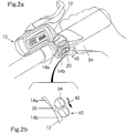
- Figs. 1a and 1b show a bicycle rider placing his thumb on the switch guide 20 and moving his thumb to a first side 36 of the switch guide 20, in the direction shown by the arrow 38, to access switch 14a.
- Figs. 2a and 2b show a bicycle rider placing his thumb on the switch guide 20 and moving his thumb to a second side of the 40 of the switch guide 20, in the direction shown by the ai-row 42, to access switch 14b.
- switch guide of the present invention guides a bicycle rider to the correct switch without requiring the rider to look down at the control panel. Furthermore, it would require minimal effort for the rider to use the switch guide. Even in the roughest and bumpiest terrain, the rider can quickly and easily access the desired switches without having to worry about activating the incorrect switch.
Landscapes
- Engineering & Computer Science (AREA)
- Mechanical Engineering (AREA)
- Chemical & Material Sciences (AREA)
- Combustion & Propulsion (AREA)
- Transportation (AREA)
- Steering Devices For Bicycles And Motorcycles (AREA)
Abstract
Description
Claims (17)
- A computerized bicycle control panel (10), comprising: a pair of switches (14a, 14b); and a protrusion (20) positioned between the switches (14a, 14b).
- A bicycle control panel (10) in accordance with claim 1, wherein each switch (14a, 14b) has a switch height (26), the protrusion (20) has a protrusion height, and the protrusion height is greater than the switch height (26).
- A bicycle control panel (10) in accordance with claim 1, wherein each switch (14a, 14b) defines an first height (24) when the switch is at an initial rest position and a second height (26) when the switch is at an activated position, and wherein the protrusion (20) has a protrusion height that is greater than the second height (26) of the switch when the switch is at the activated position.
- A bicycle control panel (10) in accordance with any of the preceding claims wherein the protrusion (20) has a rectangular cross-section.
- A control panel (10), comprising:
a pair of function keys (14a, 14b), each function key (14a, 14b) having a length, the pair of function keys (14a, 14b) defining a region there between, wherein the region does not extend beyond the length of the function keys (14a, 14b); and a guide (20) located in the region between the pair of function keys (14a, 14b). - A control panel (10) in accordance with claim 5 wherein the guide (20) has a guide length (22) and wherein the guide length (22) is equal to the length of each function key (14a, 14b).
- A control panel (10) in accordance with claim 5 wherein the region has a length and wherein the guide occupies the entire length (18) of the region (16) and extends beyond the region.
- A control panel (10) operable with a human hand, comprising:
a pair of keys (14a, 14b); and a guide (20) positioned between the pair of keys (14a, 14b), wherein the guide (20) is dimensioned to be detectable by the human hand. - A control panel (10) in accordance with claim 8 wherein the guide (20) is equidistant from each of the keys (14a, 14b).
- A control panel (10) in accordance with claim 8 or 9 wherein the guide (20) is has a rectangular cross-section.
- A control panel (10) in accordance with any of claims 8 to 10 wherein the guide (20) is rigid.
- A control panel (10) in accordance with any of claims 8 to 11 wherein the guide (20) is non-movable.
- A control panel (10) in accordance with claim 5, further comprising a control panel base (12), wherein the guide (20) is a depression defined in the control panel base (12).
- A bicycle handle, comprising:a control panel (10);a pair of switches (14a, 14b) on the control panel (10); anda protrusion (20) located between the switches (14a, 14b) on the control panel (10).
- A method of guiding a bicycle rider's thumb to a proper switch on a bicycle handle bar, comprising the steps of:providing a protrusion (20) on the bicycle handle bar, wherein the protrusion (20) is dimensioned to be detected by the bicycle rider's finger;providing a first switch (14a) positioned on a first side of the protrusion (20) and a second switch (14b) positioned on a second side of the protrusion (20), such that the protrusion (20) is located between the first switch (14a) and the second switch (14b); andwherein the first and second switches (14a, 14b) are located in sufficient proximity to the protrusion (20) to allow the thumb to access the first switch (14a) or the second switch (14b) by moving the thumb to the first side or the second side of the protrusion (20), respectively.
- A method in accordance with claim 15, further comprising the steps of:
manipulating the bicycle rider's thumb to contact the first switch (14a) or the second switch (14b) by moving the thumb to the first side or the second side of the protrusion (20), respectively. - A method in accordance with claim 15 or 16, further comprising the steps of activating either the first switch (14a) or the second switch (14b).
Applications Claiming Priority (2)
| Application Number | Priority Date | Filing Date | Title |
|---|---|---|---|
| US09/661,974 US6400564B1 (en) | 2000-09-14 | 2000-09-14 | Switch guide for a bicycle control panel |
| US661974 | 2000-09-14 |
Publications (3)
| Publication Number | Publication Date |
|---|---|
| EP1188653A2 true EP1188653A2 (en) | 2002-03-20 |
| EP1188653A3 EP1188653A3 (en) | 2005-11-16 |
| EP1188653B1 EP1188653B1 (en) | 2009-11-11 |
Family
ID=24655855
Family Applications (1)
| Application Number | Title | Priority Date | Filing Date |
|---|---|---|---|
| EP01121949A Expired - Lifetime EP1188653B1 (en) | 2000-09-14 | 2001-09-12 | A switch guide for a bicycle control panel |
Country Status (6)
| Country | Link |
|---|---|
| US (2) | US6400564B1 (en) |
| EP (1) | EP1188653B1 (en) |
| JP (1) | JP3487840B2 (en) |
| CN (1) | CN1278900C (en) |
| DE (1) | DE60140413D1 (en) |
| TW (1) | TWM244253U (en) |
Cited By (2)
| Publication number | Priority date | Publication date | Assignee | Title |
|---|---|---|---|---|
| EP2594471A4 (en) * | 2010-07-12 | 2014-09-03 | Panasonic Corp | SWITCH DEVICE FOR ELECTRIC BICYCLE, AND ELECTRIC BICYCLE |
| EP4140868A1 (en) * | 2021-08-25 | 2023-03-01 | Robert Bosch GmbH | Operational device for a single-track vehicle |
Families Citing this family (22)
| Publication number | Priority date | Publication date | Assignee | Title |
|---|---|---|---|---|
| JP4138733B2 (en) * | 2004-01-18 | 2008-08-27 | 三菱電線工業株式会社 | Grip heater control device and control method |
| USD515981S1 (en) | 2004-09-16 | 2006-02-28 | Radio Sound, Inc. | Straddled vehicle user interface for an audio system |
| US20060059294A1 (en) * | 2004-09-16 | 2006-03-16 | Smith Kevin T | Expandable bus topology for peripheral devices of straddle vehicles |
| US7641020B2 (en) * | 2005-04-18 | 2010-01-05 | Jungheinrich Aktiengessellschaft | Hand rail for a walkie/rider truck |
| US9434437B2 (en) * | 2009-07-23 | 2016-09-06 | Harley-Davidson Motor Company Group, LLC | Master cylinder-mounted display for a motorcycle |
| USD640608S1 (en) * | 2010-07-01 | 2011-06-28 | Panasonic Corporation | Operation switch for battery-assisted bicycle |
| USD718256S1 (en) * | 2012-04-06 | 2014-11-25 | The Raymond Corporation | Switch module |
| US9326412B2 (en) * | 2012-11-16 | 2016-04-26 | Shimano Inc. | Bicycle electric control device |
| JP1516296S (en) * | 2013-08-23 | 2015-01-26 | ||
| JP6420556B2 (en) * | 2014-03-24 | 2018-11-07 | 株式会社デイトナ | Operational assistant device for information terminal equipment |
| JP6797188B2 (en) * | 2015-08-25 | 2020-12-09 | バイクテック アーゲーBiketec Ag | Electric bicycle |
| US10046826B2 (en) * | 2015-08-27 | 2018-08-14 | Tektro Technology Corporation | Dual control lever and bicycle control assembly |
| JP2020125092A (en) * | 2019-02-06 | 2020-08-20 | トヨタ自動車株式会社 | Vehicular steering wheel structure |
| JP7525249B2 (en) * | 2019-05-16 | 2024-07-30 | 株式会社シマノ | An interface device for human-powered vehicles. |
| US11407474B2 (en) * | 2019-07-29 | 2022-08-09 | Shimano Inc. | Operating device for human-powered vehicle |
| CN112590997B (en) * | 2020-12-24 | 2022-07-29 | 九号智能(常州)科技有限公司 | Method and device for switching modes of riding vehicle and storage medium |
| JP7796487B2 (en) * | 2021-06-30 | 2026-01-09 | 株式会社シマノ | Operating device for human-powered vehicle, and human-powered vehicle |
| JP1727396S (en) * | 2021-11-05 | 2022-10-14 | ||
| USD1059418S1 (en) | 2021-12-23 | 2025-01-28 | Stryker Corporation | Housing for a display screen |
| USD1059368S1 (en) | 2021-12-23 | 2025-01-28 | Stryker Corporation | Housing for a display screen |
| WO2024161902A1 (en) * | 2023-01-31 | 2024-08-08 | 本田技研工業株式会社 | Handlebar switch |
| US20250033724A1 (en) * | 2023-07-28 | 2025-01-30 | Shimano Inc. | Operating device of human-powered vehicle |
Citations (1)
| Publication number | Priority date | Publication date | Assignee | Title |
|---|---|---|---|---|
| JPS58195916U (en) | 1982-06-22 | 1983-12-26 | 本田技研工業株式会社 | switch device |
Family Cites Families (20)
| Publication number | Priority date | Publication date | Assignee | Title |
|---|---|---|---|---|
| FR2308910A1 (en) * | 1975-04-21 | 1976-11-19 | Genzling Claude | INTEGRATED COUNTER-TACHOMETER DEVICE FOR BICYCLES |
| US4490127A (en) * | 1981-05-29 | 1984-12-25 | Sanyo Electric Co., Ltd. | Electrically operated transmission gear system for bicycles |
| DE3132311C2 (en) * | 1981-08-17 | 1983-12-29 | Bayerische Motoren Werke AG, 8000 München | Switch assembly for motorcycles |
| US4508944A (en) * | 1982-04-05 | 1985-04-02 | Honda Motor Co., Ltd. | Handle switch assembly for motorcycles |
| US4565909A (en) * | 1982-06-09 | 1986-01-21 | Honda Kogyo Kabushiki Kaisha | Handle switch assembly for a motor vehicle |
| US4641723A (en) * | 1982-06-23 | 1987-02-10 | Honda Giken Kogyo Kabushiki Kaisha | Handle switch assembly for a motor vehicle |
| JPS60118711U (en) | 1984-01-20 | 1985-08-10 | 株式会社キャットアイ | Bicycle riding data display device |
| FR2580240B1 (en) * | 1985-04-10 | 1987-07-10 | Citroen Maxime | GROUPING DEVICE CONSTITUTING A KEYBOARD OF CONTACTORS FOR CONTROLLING EQUIPMENT INSTALLED IN A MOTOR VEHICLE |
| US4881187A (en) * | 1988-02-25 | 1989-11-14 | Schwinn Bicycle Company | Cycle computer with improved switch and push-button arrangement to facilitate resetting |
| JPH0275211U (en) * | 1988-11-25 | 1990-06-08 | ||
| DE3924292C1 (en) * | 1989-07-22 | 1990-12-06 | Daimler-Benz Aktiengesellschaft, 7000 Stuttgart, De | |
| JPH04104793U (en) | 1991-02-22 | 1992-09-09 | 株式会社キヤツトアイ | Motorcycle parts |
| US5213548A (en) * | 1992-03-02 | 1993-05-25 | Colbert Ralph G | Gear shifting system for derailleur equipped bicycle |
| JP2999908B2 (en) * | 1993-09-08 | 2000-01-17 | 株式会社シマノ | Bicycle display device |
| JP3005204B2 (en) * | 1997-03-31 | 2000-01-31 | 株式会社シマノ | Bicycle motor control device |
| JP3474080B2 (en) * | 1997-05-16 | 2003-12-08 | 株式会社シマノ | Bicycle switch |
| US6069788A (en) | 1997-06-28 | 2000-05-30 | Shimano, Inc. | Foldable bicycle computer |
| US6167774B1 (en) * | 1999-02-08 | 2001-01-02 | Bombardier, Inc. | Handlebar-mountable ergonomic shifter for a motor vehicle |
| US6204752B1 (en) * | 1999-11-24 | 2001-03-20 | Shimano Inc. | Bicycle display unit with backlight |
| US6317036B1 (en) * | 2000-01-13 | 2001-11-13 | Pradeep P. Popat | Voice alert system for use on bicycles and the like |
-
2000
- 2000-09-14 US US09/661,974 patent/US6400564B1/en not_active Ceased
-
2001
- 2001-08-15 TW TW091212686U patent/TWM244253U/en not_active IP Right Cessation
- 2001-09-06 JP JP2001270382A patent/JP3487840B2/en not_active Expired - Fee Related
- 2001-09-12 EP EP01121949A patent/EP1188653B1/en not_active Expired - Lifetime
- 2001-09-12 DE DE60140413T patent/DE60140413D1/en not_active Expired - Lifetime
- 2001-09-13 CN CNB011330112A patent/CN1278900C/en not_active Expired - Fee Related
-
2004
- 2004-06-25 US US10/877,973 patent/USRE41194E1/en not_active Expired - Lifetime
Patent Citations (1)
| Publication number | Priority date | Publication date | Assignee | Title |
|---|---|---|---|---|
| JPS58195916U (en) | 1982-06-22 | 1983-12-26 | 本田技研工業株式会社 | switch device |
Cited By (2)
| Publication number | Priority date | Publication date | Assignee | Title |
|---|---|---|---|---|
| EP2594471A4 (en) * | 2010-07-12 | 2014-09-03 | Panasonic Corp | SWITCH DEVICE FOR ELECTRIC BICYCLE, AND ELECTRIC BICYCLE |
| EP4140868A1 (en) * | 2021-08-25 | 2023-03-01 | Robert Bosch GmbH | Operational device for a single-track vehicle |
Also Published As
| Publication number | Publication date |
|---|---|
| CN1278900C (en) | 2006-10-11 |
| EP1188653A3 (en) | 2005-11-16 |
| EP1188653B1 (en) | 2009-11-11 |
| CN1343598A (en) | 2002-04-10 |
| US6400564B1 (en) | 2002-06-04 |
| DE60140413D1 (en) | 2009-12-24 |
| JP3487840B2 (en) | 2004-01-19 |
| USRE41194E1 (en) | 2010-04-06 |
| JP2002087362A (en) | 2002-03-27 |
| TWM244253U (en) | 2004-09-21 |
Similar Documents
| Publication | Publication Date | Title |
|---|---|---|
| US6400564B1 (en) | Switch guide for a bicycle control panel | |
| EP1391377B1 (en) | Electrical shift control device for a bicycle transmission | |
| JP5963857B2 (en) | Vehicle shift device | |
| US20020152827A1 (en) | Shift device and switch device thereof for vehicle | |
| KR101596706B1 (en) | Simultaneously manipulatable electronic automatic transmission lever and control method thereof | |
| US20030074997A1 (en) | Electronic shifter for a bicycle | |
| JP2006298241A (en) | Vehicle display device | |
| JP2001160336A (en) | Operation switch device for vehicles | |
| US20070186704A1 (en) | Control apparatus of vehicular automatic transmission | |
| US20040001097A1 (en) | Glove virtual keyboard for baseless typing | |
| JP2022108716A (en) | Driving assist device | |
| JP2000071801A (en) | Steering operation lever of working vehicle | |
| CN101676141A (en) | Vehicle steering control | |
| JP2008265732A (en) | Control device for bicycle and bicycle comprising the device | |
| JP2003205759A (en) | Automatic transmission shift switch | |
| US20230365217A1 (en) | Manual control device for a bicycle | |
| JP2003208831A (en) | Switch case for handlebar | |
| JPH06139878A (en) | Controller for video game console | |
| JP5042214B2 (en) | Shift control device for vehicle speed ratio near steering wheel | |
| CN215950344U (en) | Key-type gear shifter | |
| JPH0533816Y2 (en) | ||
| JPH0227470Y2 (en) | ||
| CN113236762A (en) | Key-type gear shifter | |
| CN120756607A (en) | Controls for bicycles equipped with aerobars | |
| CN212593934U (en) | Anti-skid wireless gamepad |
Legal Events
| Date | Code | Title | Description |
|---|---|---|---|
| PUAI | Public reference made under article 153(3) epc to a published international application that has entered the european phase |
Free format text: ORIGINAL CODE: 0009012 |
|
| AK | Designated contracting states |
Kind code of ref document: A2 Designated state(s): AT BE CH CY DE DK ES FI FR GB GR IE IT LI LU MC NL PT SE TR |
|
| AX | Request for extension of the european patent |
Free format text: AL;LT;LV;MK;RO;SI |
|
| PUAL | Search report despatched |
Free format text: ORIGINAL CODE: 0009013 |
|
| AK | Designated contracting states |
Kind code of ref document: A3 Designated state(s): AT BE CH CY DE DK ES FI FR GB GR IE IT LI LU MC NL PT SE TR |
|
| AX | Request for extension of the european patent |
Extension state: AL LT LV MK RO SI |
|
| 17P | Request for examination filed |
Effective date: 20060323 |
|
| AKX | Designation fees paid |
Designated state(s): DE FR GB IT NL |
|
| RAP1 | Party data changed (applicant data changed or rights of an application transferred) |
Owner name: SHIMANO INC. |
|
| 17Q | First examination report despatched |
Effective date: 20071113 |
|
| GRAP | Despatch of communication of intention to grant a patent |
Free format text: ORIGINAL CODE: EPIDOSNIGR1 |
|
| GRAJ | Information related to disapproval of communication of intention to grant by the applicant or resumption of examination proceedings by the epo deleted |
Free format text: ORIGINAL CODE: EPIDOSDIGR1 |
|
| GRAP | Despatch of communication of intention to grant a patent |
Free format text: ORIGINAL CODE: EPIDOSNIGR1 |
|
| RIC1 | Information provided on ipc code assigned before grant |
Ipc: B62J 99/00 20090101AFI20090604BHEP |
|
| GRAS | Grant fee paid |
Free format text: ORIGINAL CODE: EPIDOSNIGR3 |
|
| GRAA | (expected) grant |
Free format text: ORIGINAL CODE: 0009210 |
|
| AK | Designated contracting states |
Kind code of ref document: B1 Designated state(s): DE FR GB IT NL |
|
| REG | Reference to a national code |
Ref country code: GB Ref legal event code: FG4D |
|
| REF | Corresponds to: |
Ref document number: 60140413 Country of ref document: DE Date of ref document: 20091224 Kind code of ref document: P |
|
| NLV1 | Nl: lapsed or annulled due to failure to fulfill the requirements of art. 29p and 29m of the patents act | ||
| PLBE | No opposition filed within time limit |
Free format text: ORIGINAL CODE: 0009261 |
|
| STAA | Information on the status of an ep patent application or granted ep patent |
Free format text: STATUS: NO OPPOSITION FILED WITHIN TIME LIMIT |
|
| 26N | No opposition filed |
Effective date: 20100812 |
|
| GBPC | Gb: european patent ceased through non-payment of renewal fee |
Effective date: 20100912 |
|
| REG | Reference to a national code |
Ref country code: FR Ref legal event code: ST Effective date: 20110531 |
|
| PG25 | Lapsed in a contracting state [announced via postgrant information from national office to epo] |
Ref country code: FR Free format text: LAPSE BECAUSE OF NON-PAYMENT OF DUE FEES Effective date: 20100930 |
|
| PG25 | Lapsed in a contracting state [announced via postgrant information from national office to epo] |
Ref country code: GB Free format text: LAPSE BECAUSE OF NON-PAYMENT OF DUE FEES Effective date: 20100912 |
|
| PG25 | Lapsed in a contracting state [announced via postgrant information from national office to epo] |
Ref country code: NL Free format text: LAPSE BECAUSE OF FAILURE TO SUBMIT A TRANSLATION OF THE DESCRIPTION OR TO PAY THE FEE WITHIN THE PRESCRIBED TIME-LIMIT Effective date: 20091111 |
|
| PGFP | Annual fee paid to national office [announced via postgrant information from national office to epo] |
Ref country code: DE Payment date: 20140911 Year of fee payment: 14 |
|
| PGFP | Annual fee paid to national office [announced via postgrant information from national office to epo] |
Ref country code: IT Payment date: 20150925 Year of fee payment: 15 |
|
| REG | Reference to a national code |
Ref country code: DE Ref legal event code: R119 Ref document number: 60140413 Country of ref document: DE |
|
| PG25 | Lapsed in a contracting state [announced via postgrant information from national office to epo] |
Ref country code: DE Free format text: LAPSE BECAUSE OF NON-PAYMENT OF DUE FEES Effective date: 20160401 |
|
| PG25 | Lapsed in a contracting state [announced via postgrant information from national office to epo] |
Ref country code: IT Free format text: LAPSE BECAUSE OF NON-PAYMENT OF DUE FEES Effective date: 20160912 |