EP1188639A1 - Dispositif de direction de véhicule automobile - Google Patents
Dispositif de direction de véhicule automobile Download PDFInfo
- Publication number
- EP1188639A1 EP1188639A1 EP01402369A EP01402369A EP1188639A1 EP 1188639 A1 EP1188639 A1 EP 1188639A1 EP 01402369 A EP01402369 A EP 01402369A EP 01402369 A EP01402369 A EP 01402369A EP 1188639 A1 EP1188639 A1 EP 1188639A1
- Authority
- EP
- European Patent Office
- Prior art keywords
- steering
- locking
- unlocking
- control member
- steering column
- Prior art date
- Legal status (The legal status is an assumption and is not a legal conclusion. Google has not performed a legal analysis and makes no representation as to the accuracy of the status listed.)
- Granted
Links
Images




Classifications
-
- B—PERFORMING OPERATIONS; TRANSPORTING
- B62—LAND VEHICLES FOR TRAVELLING OTHERWISE THAN ON RAILS
- B62D—MOTOR VEHICLES; TRAILERS
- B62D1/00—Steering controls, i.e. means for initiating a change of direction of the vehicle
- B62D1/02—Steering controls, i.e. means for initiating a change of direction of the vehicle vehicle-mounted
- B62D1/04—Hand wheels
- B62D1/10—Hubs; Connecting hubs to steering columns, e.g. adjustable
- B62D1/105—Non-rotatable hubs, e.g. the central part of the steering wheel not rotating
-
- B—PERFORMING OPERATIONS; TRANSPORTING
- B62—LAND VEHICLES FOR TRAVELLING OTHERWISE THAN ON RAILS
- B62D—MOTOR VEHICLES; TRAILERS
- B62D1/00—Steering controls, i.e. means for initiating a change of direction of the vehicle
- B62D1/02—Steering controls, i.e. means for initiating a change of direction of the vehicle vehicle-mounted
- B62D1/16—Steering columns
- B62D1/18—Steering columns yieldable or adjustable, e.g. tiltable
- B62D1/184—Mechanisms for locking columns at selected positions
Definitions
- the present invention relates to a steering device for motor vehicle.
- the invention relates more particularly to a device for motor vehicle steering which has a column of longitudinal tubular direction in which is rotatably mounted a direction tree.
- a steering wheel is linked in rotation to the free upper end of the steering shaft.
- the steering wheel generally has an annular rim which is connected, by branches of substantially radial orientation, to a flywheel hub which is itself linked in rotation to the end upper free of the steering shaft.
- such a steering device may have a central block which is mounted in the center of the steering wheel and which is fixed in rotation relative to the steering column, that is to say that it does not turn with the steering wheel.
- This stationary arrangement in rotation of the block, while allowing a drive in rotation of the steering shaft by the flywheel is obtained by a gear mechanism which is integrated inside the steering column.
- such a steering device may include a device for adjusting the position of the steering column in a vertical median plane of longitudinal direction. To do this, it has a device for locking and unlocking its position in relation to the structure of the vehicle. The device locking and unlocking is actuated in a known manner by a control member which is mounted movable relative to the steering column.
- the locking and unlocking device is generally arranged under the steering column. So, for adjust the steering wheel position with the driver of the vehicle seated must lean forward to access the movable member and to unlock the adjuster. The driver's position does does not correspond to his driving position, he must then return to rear put both hands on the steering wheel to adjust properly the position of the steering column and the steering wheel. He must then maintain the steering wheel so as to maintain its position, then lean forward again and reach out to maneuver the movable member and again lock the adjustment device.
- control member under the steering column does not allow to highlight it. The driver's attention is therefore not drawn to the presence of the adjustment device, which does not encourage him to use it.
- the object of the invention is to propose a device for direction which overcomes the disadvantages that come to be mentioned.
- the invention proposes a device for directing motor vehicle of the type comprising a steering column longitudinal tubular, a steering shaft mounted rotating at inside the steering column, a steering wheel linked in rotation at the free upper end of the steering shaft, a block mounted in the center of the steering wheel and fixed in rotation relative to the steering column, via a tubular support or ferrule coaxial with the steering shaft, and of the type comprising a steering column position adjusting device, in a vertical plane of longitudinal direction, which includes a device for locking and unlocking its position which is actuated by a control member mounted movable between a locking position and an unlocking position of the steering column position adjustment device, characterized in that the control member is mounted in the fixed block.
- a front, rear orientation will be used, without limitation, in reference to a left-to-right orientation according to the figure 1.
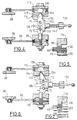
- FIG. 1 represents a device 10 for steering motor vehicle.
- the steering device 10 comprises mainly a steering column 12 of general shape tubular general orientation of axis X-X
- the vehicle steering device 10 here comprises a symmetry with respect to a vertical median plane P of direction longitudinal.
- the median plane P corresponds to the plane of the section of Figure 1.
- a steering shaft 14 is mounted rotating in the column direction 12. It transmits the rotational movement from a steering wheel 16 to a device for orienting the wheels of the vehicle, not shown.
- the steering wheel 16 essentially consists of a rim 20 generally annular in shape which is connected by branches 22 (only one of which is shown in Figure 1) to a flywheel hub 24.
- a fixed block 26 is arranged in the center of the steering wheel 16, that is to say inside the rim 20 between the branches 22.
- the block 26 is stationary in rotation around the X-X axis, i.e. it does not not turn with the steering wheel 16.
- the fixed block 26 is connected by means not shown in column 12 of direction.
- a ferrule 28, also called a tubular support, is fixed by example by tight mounting or by welding on the free end of the steering column 12. It protects a device 30 from transmission of the rotational movement of the flywheel 16 to the shaft 18 of rotation.
- the rear section of the ferrule 28 receives a toothed sleeve 40, free to rotate, which has at its longitudinal end front, a series of teeth 42 and, at its longitudinal end opposite rear, another set of teeth 44.
- the sets of teeth 42 and 44 are separated by a concave and smooth cylindrical section of the internal wall of the toothed sleeve 40.
- teeth 46 distributed over the outer periphery of a sprocket 48 of the flywheel hub 24 allows the meshing of teeth 44 of the toothed sleeve 40.
- the toothed sleeve 40 is thus caused rotation by the steering wheel 16.
- the hub pinion 48 is produced integrally in one single piece with the hub 24 of the flywheel 16 from which it extends longitudinally towards the steering column 12.
- the external cylindrical wall 50 of the toothed sleeve 40 is rotationally mounted relative to the ferrule 28 by interposition of bearings 52 for example ball or needle. According to one variant a self-lubricating type friction ring can also be interposed.
- the rotation of the toothed sleeve 40 allows to drive in rotation of the corresponding teeth 54 of a pinion 56.
- the pinion 56 has an axis 58 rotatably mounted by through bearings 60 interposed between axis 58 and bearings made in an intermediate element for holding and guide 70.
- the axis 58 is stationary relative to the steering column 12.
- the pinion 56 has a diameter which is small compared to to the diameter of the ferrule 28. In fact, its diameter here corresponds substantially a quarter of the diameter of the ferrule 28.
- the front section of the teeth 54 meshes with teeth 62 which are distributed over the interior surface of a cup 64 which is integral with the rotation shaft 18.
- the cup 64 is fixed to the rotation shaft 18 for example by shrinking a portion 66 of cylindrical shape extending longitudinally forward inside the hollow rear section of the rotation shaft 18.
- the rotational movement of the steering wheel 16 is transmitted to the rotation shaft 18 via the toothed sleeve 40 and pinion 56.
- the fixed block 26 is connected to the steering column 12 in particular by the intermediate holding and guiding element 70.
- An adjustment device 80 is arranged close to the rear end of the steering column 12. It allows the driver to adjust the position of the steering wheel, in a vertical plane of longitudinal direction, according to its morphology so as to drive the vehicle in an optimal position which allows reduce fatigue and therefore increase safety.
- the adjustment device 80 includes a device 82 for locking and unlocking which allows to block or release the movement of the steering column in the vertical plane longitudinal direction.
- the device 82 for locking and unlocking is actuated by a control member 84 which is mounted movable between a locking position which is shown in Figure 1 and an unlocked position which is shown in Figure 2, the control member 84 being mounted in the fixed block 26.
- the adjusting device 80 comprises a pair of firsts 86 adjustment legs and a pair of second adjustment legs 88, which are parallel to the median plane P, so as to form two pairs of legs 86 and 88 which each consist of a leg 86 and a leg 88 and which are arranged on either side of the steering column 18.
- the legs 86 and 88 are here substantially oriented perpendicular to each other, the first leg 86 being parallel to the longitudinal axis X-X.
- Each adjustment leg 86 and 88 has a first end 90, 92 which is pivotally mounted about an axis 94, 96 respectively of transverse orientation and belonging to the vehicle structure 98.
- the second ends 100, 102 of legs 86 and 88 are juxtaposed and comprise guide means 104 and 106 of a connecting element 108 integral with the steering column 12.
- the guide means 104 and 106 consist of lights oblong in radial orientation with respect to the transverse axis of rotation of the first end 90 and 92 respectively. So the lights of the guide means 104 are, in the first position of the steering column 12 shown in FIG. 1, parallel to the longitudinal axis X-X. The lights means guide 106 are then of orientation substantially perpendicular to the longitudinal axis X-X.
- the lights are crossed transversely by holding means constituted here by a bolt 109 of the element 108.
- each leg 86 and 88 is constituted by the juxtaposition of three sides, which consist here of cut sheets.
- the second ends of the sheets constituting the first and the second leg 86, 88 of each pair are stacked with alternately. In addition, they are arranged between cams 110 and a stop 112.
- Each cam 110 has a first end 128 articulation and a second end 115 of support.
- a pressure block 114 is interposed between the second free ends 115 of the cams 110 and the second ends of legs 86 and 88.
- the block of pressure 114 is part of the connecting element 108.
- the connecting element 108 also includes a collar 116 which surrounds the steering column 12.
- the collar 116 is mounted in translation inside a longitudinal groove 118 of the vehicle structure. So the transverse efforts that are exerted on the locking and unlocking device 82 are taken up by the connection between the collar 116 and the groove longitudinal 118 so as to avoid any transverse overload legs 86 and 88 which could deform them and block the adjusting device 80.
- cams 110 There are four cams 110 here, they are articulated in rotation, near their first free end 128, in pairs around axes Y1 and Y2 which are integral with a body 130 which is movable in translation in the direction longitudinal X-X.
- the second free ends 115 of the cams 110 penetrate inside notches 134 of substantially cross section triangular, shown in Figures 4 and 6.
- the notches 134 allow a slight movement, generally of rotation, of the second free ends 115 of the cams 110.
- the body 130 has a groove 132 crossed by the bolt 109 and which allows its guiding in translation.
- the operation of the locking device 82 and unlocking is as follows.
- the device 82 of locking and unlocking allows locking, or locking, of the position of the steering column 12.
- the body 130 is in a front locking position so that the bottoms 136 of the notches 134 are aligned with a straight line D passing by the axes Y1 and Y2 of rotation of the cams 110 and shown at Figure 4.
- the second free ends 115 of the cams 110 press the pressure blocks 114 towards the outside of the device 82 in the direction of the stops 112, so as to pinch the seconds ends 100 and 102 of the sheets constituting the legs 86 and 88 juxtaposed and alternated according to figure 5.
- the shape of the first free ends 128 consists of an arc whose diameter corresponds to the half the distance between the axes Y1 and Y2. So in position locking, the cams 110 are braced two by two.
- the surfaces of the stops 112 and of the blocks pressure 114 in contact with a lateral surface of a sheet constituting a leg 86 or 88 are covered with a layer of material 138 with a high coefficient of friction for increase the forces ensuring the locking of the device 82.
- a return spring 140 permanently exerts a force oriented forward, the bottom of the groove 130 then being in support against bolt 109.
- the body 130 is here pulled backwards by means of a drive bar 150, in accordance in Figure 6.
- the drive bar 150 is guided in translation by a guide zone 148 of the intermediate element holding and guiding 70.
- the return spring 140 is here wound around the bar 150. This thus helps guide it and avoid its transverse deformation.
- the backward movement of body 130 causes the displacement of the axes Y1 and Y2 of rotation of the cams 110 and, by Consequently, a global movement of rotation of the latter.
- Their first free ends 136 approach one of the other so as to release the pressure on the pressure blocks 114.
- the surfaces of the second ends 100, 102 of the sheets constituting the juxtaposed and alternating legs 86 and 88 are not then no longer in contact in accordance with FIG. 7.
- the legs 86 and 88 are no longer immobilized with respect to each other, this which allows the displacement of the steering column 12.
- FIG. 2 represents the device for direction 10 in a second position, the device 82 of locking and unlocking being in position unlocking. It can be seen that the bolt 109 has moved by relative to the guide means 104 and 106.
- the drive bar 150 is connected to a member 84, which here is a lever, via means of translation 152.
- the lever 84 is mounted articulated at one of its ends free 154 around a hinge axis 156 of transverse orientation, between a locking position, shown in figure 1, and an unlocking position, shown in FIG. 2.
- the translation means 152 make it possible to transform the movement of rotation of lever 84 in a movement of translation and then transmit it to the device lock 82.
- the translation means 152 here consist of a rod 164 and a rocker lever 166.
- the rod 164 is mounted in translation inside a part of the intermediate holding and guiding element 70, its rear end 168 is in contact with an intermediate section 170 of the lever 84, and its front end 180 allows to drive in rotation of a first end 182 of the rocking lever 166.
- the rocking lever 166 is articulated around an axis of tipping 184 which is here located near a second end 186 of rocker lever 166 so as to gear down the force exerted by the rod 164.
- the rocking lever 166 allows the translation means 152 to radially cross the ferrule 28.
- the second end 186 is connected to the free end rear of the drive bar 150 by sliding a pawn 187 in an oblong light 189 of perpendicular orientation to the axis of the bar 150.
- the rocking lever 166 makes it possible to transform the forward movement of the rod 164 in a translational movement towards the rear of the bar drive 150 and vice versa.
- the return spring 140 applies a drive force according to a movement contrary to that which has just been described. So when the force F is released at the end 158 of the lever 84, the spring 140 returns the body 130 and the lever 84 to the position locking.
- the second free end 158 of the lever 84 is in abutment against a first stop 160 of a central cushion 162 of the fixed block 26.
- the central cushion 162 can be the protective cover of a safety device, not shown, such as an airbag.
- the translation means 152 comprise a tube 188 in which is arranged a series of adjacent balls 190 of diameter complementary to the inner diameter of the tube 188 which are guided in translation. Each end ball 192 and 194 in the series is in contact with the rod 164 and the bar 150 respectively.
- the tube 188 allows the translation means 152 to radially cross the ferrule 28.
- the movement of the lever 84 between its locked position and its unlocked position causes a forward movement of the body 130.
- a spring 196 is interposed between a stirrup 198, articulated in rotation around a axis which here is advantageously the articulation axis 94 of the first end 90 of legs 86, and body 130 so as to return to a rear locking position.
- the shape of the notches 134 is modified to take into account counts the inversion of the direction of movement of the body 130 for move from its locked position to its position unlocking and vice versa.
- the user of the vehicle To unlock the steering device 10, the user of the vehicle, staying in its sitting position which corresponds to its driving position, apply a simple force F on the free end 158 of the control lever 84. It can then easily adjust the position of the steering wheel 16, then release the force F so that the return spring 140, 196 locks the device steering 10, as well as the position of the steering wheel 16.
- the steering wheel position adjustment operation is simple and fast since it requires no movement of the bust of the driver.
- the lever 84 is located in the center of the steering wheel 16 in the driver's field of vision, which reminds him the possibility of adjustment.
- the device adjustment can be adapted so that unlocking the device resulting from a pull of the free end of the lever oriented from front to back. It is thus for example possible to replace the return spring, which is a spring compression, by a tension spring. It is then necessary to modify the shape of the notches so as to allow rotation cams to allow movement of the second ends free and locking and unlocking the device direction.
- the return spring which is a spring compression
Landscapes
- Engineering & Computer Science (AREA)
- Chemical & Material Sciences (AREA)
- Combustion & Propulsion (AREA)
- Transportation (AREA)
- Mechanical Engineering (AREA)
- Steering Controls (AREA)
- Lock And Its Accessories (AREA)
Abstract
Description
- l'organe de commande est un levier qui est monté articulé à l'une de ses extrémités libres, entre la position de verrouillage et la position de déverrouillage ;
- l'axe d'articulation du levier est d'orientation sensiblement transversale ;
- des moyens de translation sont interposés entre l'organe de commande et le dispositif de verrouillage et de déverrouillage de façon à transmettre le mouvement de l'organe de commande au dispositif de verrouillage et de déverrouillage ;
- les moyens de translation traversent radialement le support tubulaire ;
- les moyens de translation comportent au moins un levier basculeur articulé dont chaque extrémité est en contact avec les moyens de translation et le dispositif de verrouillage et de déverrouillage respectivement ;
- l'axe d'articulation du levier basculeur est d'orientation sensiblement transversale ;
- les moyens de translation comportent un tube dans lequel est agencée une série de billes adjacentes de diamètre complémentaire au diamètre intérieur du tube qui sont guidées en translation, dans lequel chaque bille d'extrémité de la série coopère avec l'organe de commande et le dispositif de verrouillage et de déverrouillage respectivement ;
- le dispositif de verrouillage et de déverrouillage comporte au moins une came articulée à une première extrémité, entre une position de verrouillage, et une position de déverrouillage qui verrouille et déverrouille respectivement le dispositif de réglage, et en position de verrouillage la seconde extrémité libre de la came appuie transversalement sur le dispositif de réglage de façon à verrouiller sa position ;
- le dispositif de réglage comporte au moins une première et une seconde jambes de réglage, sensiblement perpendiculaires entre elles, qui sont parallèles au plan médian et dont chaque jambe comporte une première extrémité qui est montée pivotante autour d'un axe transversal différent, les secondes extrémités des jambes sont juxtaposées et comportent des moyens de guidage d'un élément de liaison solidaire de la colonne de direction, et les deux secondes extrémités de chaque jambe sont pincées entre au moins une came et une buté lorsque le dispositif de verrouillage et de déverrouillage est en position de verrouillage, de façon à immobiliser l'élément de liaison ;
- les moyens de guidage de chaque seconde extrémité libre comporte une boutonnière oblongue d'orientation radiale par rapport à l'axe transversal de rotation de la première extrémité respective, et l'élément de liaison comporte un axe qui est mobile en translation radiale dans chaque évidement oblong lorsque le dispositif déverrouillage et de déverrouillage est en position de déverrouillage ;
- le dispositif de verrouillage et de déverrouillage comporte deux paires de première et de deuxième cames qui sont articulées autour d'un premier et d'un second axe respectivement, parallèles entre eux, et qui sont d'orientation opposée, et au moins une paire de jambes de réglage est agencée de chaque côté du dispositif de verrouillage et de déverrouillage de façon qu'en position de verrouillage, les secondes extrémités des cames de chaque paire de cames et deux butées pincent les secondes extrémités d'au moins deux jambes de réglage en vis-à-vis, de façon à immobiliser l'élément de liaison.
- la figure 1 est une vue en section longitudinale partielle d'un dispositif de direction de véhicule automobile, selon l'invention, dans une première position ;
- la figure 2 est une vue similaire à celle représentée à la figure précédente, le dispositif de direction du véhicule automobile étant dans une seconde position ;
- la figure 3 est une vue en section selon la ligne 3-3 de la figure 1 ;
- la figure 4 est une vue en section partielle selon la ligne 4-4 de la figure 3 le dispositif de réglage du dispositif de direction étant dans une position verrouillée ;
- la figure 5 représente en détail une partie de la vue représentée à la figure 4 ;
- la figure 6 est une vue similaire à cette représentée à la figure 4, le dispositif de réglage étant dans une position déverrouillée ;
- la figure 7 représente en détail une partie de la vue représentée à la figure 6 ;
- la figure 8 est une vue en section longitudinale partielle d'un dispositif de direction de véhicule automobile, selon une variante de l'invention ;
- la figure 9 est une vue en section partielle similaire à celle représentée à la figure 4 du dispositif de direction de véhicule automobile, selon la variante de l'invention.
Claims (12)
- Dispositif de direction (10) de véhicule automobile du type comportant une colonne de direction (12) tubulaire longitudinale, un arbre de direction (18) monté tournant à l'intérieur de la colonne de direction (12), un volant de direction (16) lié en rotation à l'extrémité supérieure libre de l'arbre de direction (18), un bloc (26) monté au centre du volant (16) et fixe en rotation par rapport à la colonne de direction (12), par l'intermédiaire d'un support tubulaire ou virole (28) coaxial à l'arbre de direction (18), et du type comportant un dispositif (80) de réglage de la position de la colonne de direction (12), dans un plan vertical (P) de direction longitudinale, qui comporte un dispositif (82) de verrouillage et de déverrouillage de sa position qui est actionné par un organe de commande (84) monté mobile entre une position de verrouillage et une position de déverrouillage du dispositif (80) de réglage de la position de la colonne de direction (12), caractérisé en ce que l'organe de commande (84) est monté dans le bloc fixe (26).
- Dispositif de direction (10) selon la revendication précédente, caractérisé en ce que l'organe de commande (84) est un levier qui est monté articulé à l'une de ses extrémités libres (154) autour d'un axe d'articulation (156), entre la position de verrouillage et la position de déverrouillage.
- Dispositif de direction (10) selon la revendication précédente, caractérisé en ce que l'axe d'articulation (156) du levier est d'orientation sensiblement transversale.
- Dispositif de direction (10) selon l'une quelconque des revendications précédentes, caractérisé en ce que des moyens de translation (152) sont interposés entre l'organe de commande (84) et le dispositif (82) de verrouillage et de déverrouillage de façon à transmettre le mouvement de l'organe de commande (84) au dispositif (82) de verrouillage et de déverrouillage.
- Dispositif de direction (10) selon la revendication précédente, caractérisé en ce que les moyens de translation (152) traversent radialement le support tubulaire (28).
- Dispositif de direction (10) selon la revendication l'une des revendications 4 ou 5, caractérisé en ce que les moyens de translation (152) comportent au moins un levier basculeur (166) qui est articulé autour d'un axe d'articulation (184) et dont chaque extrémité (182, 186) coopère avec l'organe de commande (84) et le dispositif (82) de verrouillage et de déverrouillage respectivement.
- Dispositif de direction (10) selon la revendication précédente, caractérisé en ce que l'axe d'articulation (184) du levier basculeur (166) est d'orientation sensiblement transversale.
- Dispositif de direction (10) selon l'une des revendications 4 ou 5, caractérisé en ce que les moyens de translation (152) comportent un tube (188) dans lequel est agencée une série de billes (190) adjacentes de diamètre complémentaire au diamètre intérieur du tube (188) qui sont guidées en translation, dans lequel chaque bille d'extrémité (192, 194) de la série coopère avec l'organe de commande (84) et le dispositif (82) de verrouillage et de déverrouillage respectivement.
- Dispositif de direction (10) selon l'une quelconque des revendications précédentes, caractérisé en ce que le dispositif (82) de verrouillage et de déverrouillage comporte au moins une came (110) articulée à une première extrémité (128), entre une position de verrouillage, et une position de déverrouillage qui verrouille et déverrouille respectivement le dispositif (80) de réglage, et en ce qu'en position de verrouillage une seconde extrémité libre (115) de la came (110) appuie transversalement sur le dispositif (80) de réglage de façon à verrouiller sa position.
- Dispositif de direction (10) selon la revendication précédente, caractérisé en ce que le dispositif (80) de réglage comporte au moins une première et une seconde jambe (86, 88) de réglage, sensiblement perpendiculaires entre elles, qui sont parallèles au plan médian (P) et dont chaque jambe (86, 88) comporte une première extrémité (90, 92) qui est montée pivotante autour d'un axe transversal (92, 94) différent, en ce que les secondes extrémités (100, 102) des jambes (86, 88) sont juxtaposées et comportent des moyens de guidage (104, 106) d'un élément de liaison (108) solidaire de la colonne de direction (12), et en ce que les deux secondes extrémités (100, 102) de chaque jambe (86, 88) sont pincées entre au moins une came (110) et une butée (112) lorsque le dispositif (82) de verrouillage et de déverrouillage est en position de verrouillage, de façon à immobiliser l'élément de liaison (108).
- Dispositif de direction (10) selon la revendication précédente, caractérisé en ce que les moyens de guidage (104, 106) de chaque seconde extrémité libre (100, 102) comporte une boutonnière oblongue d'orientation radiale par rapport à l'axe transversal (94, 96) de rotation de la première extrémité (90, 92) respective, et en ce que l'élément de liaison (108) comporte une partie (109) qui est mobile en translation radiale dans chaque moyen de guidage (104, 106) lorsque le dispositif (82) de verrouillage et de déverrouillage est en position de déverrouillage.
- Dispositif de direction (10) selon l'une des revendications 10 ou 11, caractérisé en ce que le dispositif (82) de verrouillage et de déverrouillage comporte deux paires de première et de deuxième cames (110) qui sont articulées autour d'un premier et d'un second axe (Y1, Y2) respectivement, de l'élément de liaison (108), parallèles entre eux, et qui sont d'orientation opposée, et en ce qu'au moins une paire de jambes de réglage (86, 88) est agencée de chaque côté du dispositif (82) de verrouillage et de déverrouillage de façon qu'en position de verrouillage, les secondes extrémités (115) des cames (110) de chaque paire de cames (110) et deux butés (112) pincent les secondes extrémités (100, 102) d'au moins deux jambes de réglage (86, 88) en vis-à-vis, de façon à immobiliser l'élément de liaison (108) et la colonne de direction (18).
Applications Claiming Priority (2)
| Application Number | Priority Date | Filing Date | Title |
|---|---|---|---|
| FR0011894 | 2000-09-18 | ||
| FR0011894A FR2814135B1 (fr) | 2000-09-18 | 2000-09-18 | Dispositif de direction de vehicule automobile |
Publications (2)
| Publication Number | Publication Date |
|---|---|
| EP1188639A1 true EP1188639A1 (fr) | 2002-03-20 |
| EP1188639B1 EP1188639B1 (fr) | 2005-01-19 |
Family
ID=8854424
Family Applications (1)
| Application Number | Title | Priority Date | Filing Date |
|---|---|---|---|
| EP20010402369 Expired - Lifetime EP1188639B1 (fr) | 2000-09-18 | 2001-09-14 | Dispositif de direction de véhicule automobile |
Country Status (4)
| Country | Link |
|---|---|
| EP (1) | EP1188639B1 (fr) |
| DE (1) | DE60108455T2 (fr) |
| ES (1) | ES2231410T3 (fr) |
| FR (1) | FR2814135B1 (fr) |
Citations (4)
| Publication number | Priority date | Publication date | Assignee | Title |
|---|---|---|---|---|
| DE3241575A1 (de) * | 1981-11-12 | 1983-05-19 | Aisin Seiki K.K., Kariya, Aichi | Arretiermechanismus fuer ein teleskopisches lenkrad |
| JPH04129857A (ja) * | 1990-09-19 | 1992-04-30 | Mitsubishi Motors Corp | 車両のステアリング装置 |
| FR2720709A1 (fr) | 1994-06-01 | 1995-12-08 | Rech Etudes Indles Civile | Module de commande pour mécanisme de direction d'un véhicule automobile. |
| EP0983925A1 (fr) * | 1998-09-04 | 2000-03-08 | Renault | Dispositif de commande de direction de véhicule automobile comportant un bloc fixe d'accessoires agencé au centre volant |
-
2000
- 2000-09-18 FR FR0011894A patent/FR2814135B1/fr not_active Expired - Fee Related
-
2001
- 2001-09-14 DE DE2001608455 patent/DE60108455T2/de not_active Expired - Lifetime
- 2001-09-14 ES ES01402369T patent/ES2231410T3/es not_active Expired - Lifetime
- 2001-09-14 EP EP20010402369 patent/EP1188639B1/fr not_active Expired - Lifetime
Patent Citations (4)
| Publication number | Priority date | Publication date | Assignee | Title |
|---|---|---|---|---|
| DE3241575A1 (de) * | 1981-11-12 | 1983-05-19 | Aisin Seiki K.K., Kariya, Aichi | Arretiermechanismus fuer ein teleskopisches lenkrad |
| JPH04129857A (ja) * | 1990-09-19 | 1992-04-30 | Mitsubishi Motors Corp | 車両のステアリング装置 |
| FR2720709A1 (fr) | 1994-06-01 | 1995-12-08 | Rech Etudes Indles Civile | Module de commande pour mécanisme de direction d'un véhicule automobile. |
| EP0983925A1 (fr) * | 1998-09-04 | 2000-03-08 | Renault | Dispositif de commande de direction de véhicule automobile comportant un bloc fixe d'accessoires agencé au centre volant |
Non-Patent Citations (1)
| Title |
|---|
| PATENT ABSTRACTS OF JAPAN vol. 016, no. 391 (M - 1298) 19 August 1992 (1992-08-19) * |
Also Published As
| Publication number | Publication date |
|---|---|
| DE60108455T2 (de) | 2006-02-16 |
| DE60108455D1 (de) | 2005-02-24 |
| EP1188639B1 (fr) | 2005-01-19 |
| FR2814135A1 (fr) | 2002-03-22 |
| FR2814135B1 (fr) | 2002-11-15 |
| ES2231410T3 (es) | 2005-05-16 |
Similar Documents
| Publication | Publication Date | Title |
|---|---|---|
| EP0209417B1 (fr) | Perfectionnements aux appuis-tête réglables et aux sièges équipés de tels appuis-tête | |
| FR2580759A1 (fr) | Dispositif de commande du deplacement d'un element, notamment d'un siege ou des parties d'un siege d'un vehicule automobile, par rapport a un bati | |
| FR2458210A1 (fr) | Dispositif de decoupage et de transport d'un bloc de fourrage | |
| FR2739947A1 (fr) | Pedalier de vehicule automobile comportant un dispositif de reglage de la hauteur et de l'orientation des pedales | |
| FR3003925B1 (fr) | Unite motrice pour vehicule de type a selle | |
| FR2560351A1 (fr) | Machine a marche automatique conduite a la main | |
| FR2498132A1 (fr) | Dispositif de reglage en hauteur d'un element, notamment d'un siege de vehicule | |
| EP1188639B1 (fr) | Dispositif de direction de véhicule automobile | |
| FR2997054A1 (fr) | Ensemble de transmission pour engin automoteur, du type positionnable entre l'arbre primaire moteur et les roues dudit engin | |
| FR2845746A1 (fr) | Ensemble de transmission, notamment pour engin de preference a conducteur marchant et engin equipe d'un tel ensemble de transmission | |
| EP0071498B1 (fr) | Dispositif de transmission à variateur de vitesse incorporé | |
| EP1115592B1 (fr) | Siege inclinable pour enfants a cotes lateraux pivotants | |
| EP0717920B1 (fr) | Machine roulante à roues motrices perfectionnée du type tondeuse à gazon, débroussailleuse | |
| EP0948303B1 (fr) | Dispositif de blocage | |
| FR2843364A1 (fr) | Pedalier pour cycle avec un bras de levier optimise | |
| EP1234743A1 (fr) | Ensemble de colonne de direction - coussin central fixe et véhicule automobile correspondant | |
| FR2966796A1 (fr) | Guidon repliable notamment pour une motocyclette | |
| FR2528790A1 (fr) | Mecanisme de suspension de roue de vehicule avec adaptation a la charge | |
| EP2909070B1 (fr) | Ensemble de transmission pour engin automoteur et engin equipé d'une telle transmission | |
| FR2487543A1 (fr) | Commande a manivelle | |
| EP0382599A1 (fr) | Dispositif de commande de direction arrière pour véhicule automobile à quatre roues directrices | |
| FR2781747A1 (fr) | Assemblage d'un ensemble de commandes avec une colonne de direction de vehicule automobile | |
| EP4558384A1 (fr) | Vehicule de type trottinette comprenant un systeme d'actionnement muni d'un organe de guidage | |
| FR2775247A1 (fr) | Velo a cadre central formant suspension | |
| FR2777247A1 (fr) | Dispositif antivol pouvant etre fixe sur la couronne d'un volant de direction d'un vehicule automobile |
Legal Events
| Date | Code | Title | Description |
|---|---|---|---|
| PUAI | Public reference made under article 153(3) epc to a published international application that has entered the european phase |
Free format text: ORIGINAL CODE: 0009012 |
|
| AK | Designated contracting states |
Kind code of ref document: A1 Designated state(s): AT BE CH CY DE DK ES FI FR GB GR IE IT LI LU MC NL PT SE TR Kind code of ref document: A1 Designated state(s): BE DE ES GB IT |
|
| AX | Request for extension of the european patent |
Free format text: AL;LT;LV;MK;RO;SI |
|
| RAP1 | Party data changed (applicant data changed or rights of an application transferred) |
Owner name: RENAULT S.A.S. |
|
| 17P | Request for examination filed |
Effective date: 20020917 |
|
| AKX | Designation fees paid |
Free format text: BE DE ES GB IT |
|
| GRAP | Despatch of communication of intention to grant a patent |
Free format text: ORIGINAL CODE: EPIDOSNIGR1 |
|
| GRAS | Grant fee paid |
Free format text: ORIGINAL CODE: EPIDOSNIGR3 |
|
| GRAA | (expected) grant |
Free format text: ORIGINAL CODE: 0009210 |
|
| AK | Designated contracting states |
Kind code of ref document: B1 Designated state(s): BE DE ES GB IT |
|
| REG | Reference to a national code |
Ref country code: GB Ref legal event code: FG4D Free format text: NOT ENGLISH |
|
| REG | Reference to a national code |
Ref country code: IE Ref legal event code: FG4D Free format text: FRENCH |
|
| REF | Corresponds to: |
Ref document number: 60108455 Country of ref document: DE Date of ref document: 20050224 Kind code of ref document: P |
|
| GBT | Gb: translation of ep patent filed (gb section 77(6)(a)/1977) |
Effective date: 20050330 |
|
| REG | Reference to a national code |
Ref country code: ES Ref legal event code: FG2A Ref document number: 2231410 Country of ref document: ES Kind code of ref document: T3 |
|
| PLBE | No opposition filed within time limit |
Free format text: ORIGINAL CODE: 0009261 |
|
| STAA | Information on the status of an ep patent application or granted ep patent |
Free format text: STATUS: NO OPPOSITION FILED WITHIN TIME LIMIT |
|
| 26N | No opposition filed |
Effective date: 20051020 |
|
| PGFP | Annual fee paid to national office [announced via postgrant information from national office to epo] |
Ref country code: GB Payment date: 20120920 Year of fee payment: 12 |
|
| PGFP | Annual fee paid to national office [announced via postgrant information from national office to epo] |
Ref country code: ES Payment date: 20120926 Year of fee payment: 12 Ref country code: DE Payment date: 20120921 Year of fee payment: 12 |
|
| PGFP | Annual fee paid to national office [announced via postgrant information from national office to epo] |
Ref country code: BE Payment date: 20120920 Year of fee payment: 12 |
|
| PGFP | Annual fee paid to national office [announced via postgrant information from national office to epo] |
Ref country code: IT Payment date: 20120927 Year of fee payment: 12 |
|
| BERE | Be: lapsed |
Owner name: *RENAULT S.A.S. Effective date: 20130930 |
|
| GBPC | Gb: european patent ceased through non-payment of renewal fee |
Effective date: 20130914 |
|
| REG | Reference to a national code |
Ref country code: DE Ref legal event code: R119 Ref document number: 60108455 Country of ref document: DE Effective date: 20140401 |
|
| PG25 | Lapsed in a contracting state [announced via postgrant information from national office to epo] |
Ref country code: BE Free format text: LAPSE BECAUSE OF NON-PAYMENT OF DUE FEES Effective date: 20130930 Ref country code: GB Free format text: LAPSE BECAUSE OF NON-PAYMENT OF DUE FEES Effective date: 20130914 |
|
| PG25 | Lapsed in a contracting state [announced via postgrant information from national office to epo] |
Ref country code: IT Free format text: LAPSE BECAUSE OF NON-PAYMENT OF DUE FEES Effective date: 20130914 Ref country code: DE Free format text: LAPSE BECAUSE OF NON-PAYMENT OF DUE FEES Effective date: 20140401 |
|
| REG | Reference to a national code |
Ref country code: ES Ref legal event code: FD2A Effective date: 20141008 |
|
| PG25 | Lapsed in a contracting state [announced via postgrant information from national office to epo] |
Ref country code: ES Free format text: LAPSE BECAUSE OF NON-PAYMENT OF DUE FEES Effective date: 20130915 |