EP1187891B1 - Method and device for disposing of waste products - Google Patents
Method and device for disposing of waste products Download PDFInfo
- Publication number
- EP1187891B1 EP1187891B1 EP00938791A EP00938791A EP1187891B1 EP 1187891 B1 EP1187891 B1 EP 1187891B1 EP 00938791 A EP00938791 A EP 00938791A EP 00938791 A EP00938791 A EP 00938791A EP 1187891 B1 EP1187891 B1 EP 1187891B1
- Authority
- EP
- European Patent Office
- Prior art keywords
- high temperature
- synthetic gas
- oxygen
- temperature stage
- gas
- Prior art date
- Legal status (The legal status is an assumption and is not a legal conclusion. Google has not performed a legal analysis and makes no representation as to the accuracy of the status listed.)
- Expired - Lifetime
Links
Images
Classifications
-
- F—MECHANICAL ENGINEERING; LIGHTING; HEATING; WEAPONS; BLASTING
- F23—COMBUSTION APPARATUS; COMBUSTION PROCESSES
- F23G—CREMATION FURNACES; CONSUMING WASTE PRODUCTS BY COMBUSTION
- F23G5/00—Incineration of waste; Incinerator constructions; Details, accessories or control therefor
- F23G5/02—Incineration of waste; Incinerator constructions; Details, accessories or control therefor with pretreatment
- F23G5/027—Incineration of waste; Incinerator constructions; Details, accessories or control therefor with pretreatment pyrolising or gasifying stage
-
- C—CHEMISTRY; METALLURGY
- C10—PETROLEUM, GAS OR COKE INDUSTRIES; TECHNICAL GASES CONTAINING CARBON MONOXIDE; FUELS; LUBRICANTS; PEAT
- C10J—PRODUCTION OF PRODUCER GAS, WATER-GAS, SYNTHESIS GAS FROM SOLID CARBONACEOUS MATERIAL, OR MIXTURES CONTAINING THESE GASES; CARBURETTING AIR OR OTHER GASES
- C10J3/00—Production of combustible gases containing carbon monoxide from solid carbonaceous fuels
- C10J3/02—Fixed-bed gasification of lump fuel
- C10J3/06—Continuous processes
- C10J3/16—Continuous processes simultaneously reacting oxygen and water with the carbonaceous material
-
- C—CHEMISTRY; METALLURGY
- C10—PETROLEUM, GAS OR COKE INDUSTRIES; TECHNICAL GASES CONTAINING CARBON MONOXIDE; FUELS; LUBRICANTS; PEAT
- C10J—PRODUCTION OF PRODUCER GAS, WATER-GAS, SYNTHESIS GAS FROM SOLID CARBONACEOUS MATERIAL, OR MIXTURES CONTAINING THESE GASES; CARBURETTING AIR OR OTHER GASES
- C10J3/00—Production of combustible gases containing carbon monoxide from solid carbonaceous fuels
- C10J3/02—Fixed-bed gasification of lump fuel
- C10J3/20—Apparatus; Plants
- C10J3/34—Grates; Mechanical ash-removing devices
- C10J3/36—Fixed grates
-
- C—CHEMISTRY; METALLURGY
- C10—PETROLEUM, GAS OR COKE INDUSTRIES; TECHNICAL GASES CONTAINING CARBON MONOXIDE; FUELS; LUBRICANTS; PEAT
- C10J—PRODUCTION OF PRODUCER GAS, WATER-GAS, SYNTHESIS GAS FROM SOLID CARBONACEOUS MATERIAL, OR MIXTURES CONTAINING THESE GASES; CARBURETTING AIR OR OTHER GASES
- C10J3/00—Production of combustible gases containing carbon monoxide from solid carbonaceous fuels
- C10J3/58—Production of combustible gases containing carbon monoxide from solid carbonaceous fuels combined with pre-distillation of the fuel
- C10J3/60—Processes
- C10J3/64—Processes with decomposition of the distillation products
- C10J3/66—Processes with decomposition of the distillation products by introducing them into the gasification zone
-
- C—CHEMISTRY; METALLURGY
- C10—PETROLEUM, GAS OR COKE INDUSTRIES; TECHNICAL GASES CONTAINING CARBON MONOXIDE; FUELS; LUBRICANTS; PEAT
- C10J—PRODUCTION OF PRODUCER GAS, WATER-GAS, SYNTHESIS GAS FROM SOLID CARBONACEOUS MATERIAL, OR MIXTURES CONTAINING THESE GASES; CARBURETTING AIR OR OTHER GASES
- C10J3/00—Production of combustible gases containing carbon monoxide from solid carbonaceous fuels
- C10J3/72—Other features
- C10J3/723—Controlling or regulating the gasification process
-
- C—CHEMISTRY; METALLURGY
- C10—PETROLEUM, GAS OR COKE INDUSTRIES; TECHNICAL GASES CONTAINING CARBON MONOXIDE; FUELS; LUBRICANTS; PEAT
- C10K—PURIFYING OR MODIFYING THE CHEMICAL COMPOSITION OF COMBUSTIBLE GASES CONTAINING CARBON MONOXIDE
- C10K1/00—Purifying combustible gases containing carbon monoxide
- C10K1/08—Purifying combustible gases containing carbon monoxide by washing with liquids; Reviving the used wash liquors
- C10K1/10—Purifying combustible gases containing carbon monoxide by washing with liquids; Reviving the used wash liquors with aqueous liquids
- C10K1/101—Purifying combustible gases containing carbon monoxide by washing with liquids; Reviving the used wash liquors with aqueous liquids with water only
-
- F—MECHANICAL ENGINEERING; LIGHTING; HEATING; WEAPONS; BLASTING
- F23—COMBUSTION APPARATUS; COMBUSTION PROCESSES
- F23G—CREMATION FURNACES; CONSUMING WASTE PRODUCTS BY COMBUSTION
- F23G5/00—Incineration of waste; Incinerator constructions; Details, accessories or control therefor
- F23G5/08—Incineration of waste; Incinerator constructions; Details, accessories or control therefor having supplementary heating
- F23G5/12—Incineration of waste; Incinerator constructions; Details, accessories or control therefor having supplementary heating using gaseous or liquid fuel
-
- F—MECHANICAL ENGINEERING; LIGHTING; HEATING; WEAPONS; BLASTING
- F23—COMBUSTION APPARATUS; COMBUSTION PROCESSES
- F23J—REMOVAL OR TREATMENT OF COMBUSTION PRODUCTS OR COMBUSTION RESIDUES; FLUES
- F23J15/00—Arrangements of devices for treating smoke or fumes
- F23J15/02—Arrangements of devices for treating smoke or fumes of purifiers, e.g. for removing noxious material
- F23J15/04—Arrangements of devices for treating smoke or fumes of purifiers, e.g. for removing noxious material using washing fluids
-
- F—MECHANICAL ENGINEERING; LIGHTING; HEATING; WEAPONS; BLASTING
- F23—COMBUSTION APPARATUS; COMBUSTION PROCESSES
- F23J—REMOVAL OR TREATMENT OF COMBUSTION PRODUCTS OR COMBUSTION RESIDUES; FLUES
- F23J15/00—Arrangements of devices for treating smoke or fumes
- F23J15/06—Arrangements of devices for treating smoke or fumes of coolers
-
- F—MECHANICAL ENGINEERING; LIGHTING; HEATING; WEAPONS; BLASTING
- F23—COMBUSTION APPARATUS; COMBUSTION PROCESSES
- F23L—SUPPLYING AIR OR NON-COMBUSTIBLE LIQUIDS OR GASES TO COMBUSTION APPARATUS IN GENERAL ; VALVES OR DAMPERS SPECIALLY ADAPTED FOR CONTROLLING AIR SUPPLY OR DRAUGHT IN COMBUSTION APPARATUS; INDUCING DRAUGHT IN COMBUSTION APPARATUS; TOPS FOR CHIMNEYS OR VENTILATING SHAFTS; TERMINALS FOR FLUES
- F23L7/00—Supplying non-combustible liquids or gases, other than air, to the fire, e.g. oxygen, steam
- F23L7/007—Supplying oxygen or oxygen-enriched air
-
- C—CHEMISTRY; METALLURGY
- C10—PETROLEUM, GAS OR COKE INDUSTRIES; TECHNICAL GASES CONTAINING CARBON MONOXIDE; FUELS; LUBRICANTS; PEAT
- C10J—PRODUCTION OF PRODUCER GAS, WATER-GAS, SYNTHESIS GAS FROM SOLID CARBONACEOUS MATERIAL, OR MIXTURES CONTAINING THESE GASES; CARBURETTING AIR OR OTHER GASES
- C10J2200/00—Details of gasification apparatus
- C10J2200/15—Details of feeding means
- C10J2200/152—Nozzles or lances for introducing gas, liquids or suspensions
-
- C—CHEMISTRY; METALLURGY
- C10—PETROLEUM, GAS OR COKE INDUSTRIES; TECHNICAL GASES CONTAINING CARBON MONOXIDE; FUELS; LUBRICANTS; PEAT
- C10J—PRODUCTION OF PRODUCER GAS, WATER-GAS, SYNTHESIS GAS FROM SOLID CARBONACEOUS MATERIAL, OR MIXTURES CONTAINING THESE GASES; CARBURETTING AIR OR OTHER GASES
- C10J2200/00—Details of gasification apparatus
- C10J2200/15—Details of feeding means
- C10J2200/154—Pushing devices, e.g. pistons
-
- C—CHEMISTRY; METALLURGY
- C10—PETROLEUM, GAS OR COKE INDUSTRIES; TECHNICAL GASES CONTAINING CARBON MONOXIDE; FUELS; LUBRICANTS; PEAT
- C10J—PRODUCTION OF PRODUCER GAS, WATER-GAS, SYNTHESIS GAS FROM SOLID CARBONACEOUS MATERIAL, OR MIXTURES CONTAINING THESE GASES; CARBURETTING AIR OR OTHER GASES
- C10J2300/00—Details of gasification processes
- C10J2300/09—Details of the feed, e.g. feeding of spent catalyst, inert gas or halogens
- C10J2300/0903—Feed preparation
- C10J2300/0906—Physical processes, e.g. shredding, comminuting, chopping, sorting
-
- C—CHEMISTRY; METALLURGY
- C10—PETROLEUM, GAS OR COKE INDUSTRIES; TECHNICAL GASES CONTAINING CARBON MONOXIDE; FUELS; LUBRICANTS; PEAT
- C10J—PRODUCTION OF PRODUCER GAS, WATER-GAS, SYNTHESIS GAS FROM SOLID CARBONACEOUS MATERIAL, OR MIXTURES CONTAINING THESE GASES; CARBURETTING AIR OR OTHER GASES
- C10J2300/00—Details of gasification processes
- C10J2300/09—Details of the feed, e.g. feeding of spent catalyst, inert gas or halogens
- C10J2300/0913—Carbonaceous raw material
- C10J2300/0946—Waste, e.g. MSW, tires, glass, tar sand, peat, paper, lignite, oil shale
-
- C—CHEMISTRY; METALLURGY
- C10—PETROLEUM, GAS OR COKE INDUSTRIES; TECHNICAL GASES CONTAINING CARBON MONOXIDE; FUELS; LUBRICANTS; PEAT
- C10J—PRODUCTION OF PRODUCER GAS, WATER-GAS, SYNTHESIS GAS FROM SOLID CARBONACEOUS MATERIAL, OR MIXTURES CONTAINING THESE GASES; CARBURETTING AIR OR OTHER GASES
- C10J2300/00—Details of gasification processes
- C10J2300/09—Details of the feed, e.g. feeding of spent catalyst, inert gas or halogens
- C10J2300/0953—Gasifying agents
- C10J2300/0959—Oxygen
-
- C—CHEMISTRY; METALLURGY
- C10—PETROLEUM, GAS OR COKE INDUSTRIES; TECHNICAL GASES CONTAINING CARBON MONOXIDE; FUELS; LUBRICANTS; PEAT
- C10J—PRODUCTION OF PRODUCER GAS, WATER-GAS, SYNTHESIS GAS FROM SOLID CARBONACEOUS MATERIAL, OR MIXTURES CONTAINING THESE GASES; CARBURETTING AIR OR OTHER GASES
- C10J2300/00—Details of gasification processes
- C10J2300/16—Integration of gasification processes with another plant or parts within the plant
- C10J2300/1625—Integration of gasification processes with another plant or parts within the plant with solids treatment
- C10J2300/1628—Ash post-treatment
- C10J2300/1634—Ash vitrification
-
- C—CHEMISTRY; METALLURGY
- C10—PETROLEUM, GAS OR COKE INDUSTRIES; TECHNICAL GASES CONTAINING CARBON MONOXIDE; FUELS; LUBRICANTS; PEAT
- C10J—PRODUCTION OF PRODUCER GAS, WATER-GAS, SYNTHESIS GAS FROM SOLID CARBONACEOUS MATERIAL, OR MIXTURES CONTAINING THESE GASES; CARBURETTING AIR OR OTHER GASES
- C10J2300/00—Details of gasification processes
- C10J2300/18—Details of the gasification process, e.g. loops, autothermal operation
- C10J2300/1861—Heat exchange between at least two process streams
- C10J2300/1884—Heat exchange between at least two process streams with one stream being synthesis gas
-
- F—MECHANICAL ENGINEERING; LIGHTING; HEATING; WEAPONS; BLASTING
- F23—COMBUSTION APPARATUS; COMBUSTION PROCESSES
- F23G—CREMATION FURNACES; CONSUMING WASTE PRODUCTS BY COMBUSTION
- F23G2201/00—Pretreatment
- F23G2201/40—Gasification
-
- F—MECHANICAL ENGINEERING; LIGHTING; HEATING; WEAPONS; BLASTING
- F23—COMBUSTION APPARATUS; COMBUSTION PROCESSES
- F23G—CREMATION FURNACES; CONSUMING WASTE PRODUCTS BY COMBUSTION
- F23G2900/00—Special features of, or arrangements for incinerators
- F23G2900/50209—Compacting waste before burning
-
- Y—GENERAL TAGGING OF NEW TECHNOLOGICAL DEVELOPMENTS; GENERAL TAGGING OF CROSS-SECTIONAL TECHNOLOGIES SPANNING OVER SEVERAL SECTIONS OF THE IPC; TECHNICAL SUBJECTS COVERED BY FORMER USPC CROSS-REFERENCE ART COLLECTIONS [XRACs] AND DIGESTS
- Y02—TECHNOLOGIES OR APPLICATIONS FOR MITIGATION OR ADAPTATION AGAINST CLIMATE CHANGE
- Y02E—REDUCTION OF GREENHOUSE GAS [GHG] EMISSIONS, RELATED TO ENERGY GENERATION, TRANSMISSION OR DISTRIBUTION
- Y02E20/00—Combustion technologies with mitigation potential
- Y02E20/34—Indirect CO2mitigation, i.e. by acting on non CO2directly related matters of the process, e.g. pre-heating or heat recovery
Abstract
Description
Die vorliegende Erfindung bezieht sich auf ein Verfahren
und eine Vorrichtung zur Entsorgung und Nutzbarmachung
von Abfallgütern aller Art, bei dem unsortierter,
unbehandelter, beliebige Schadstoffe in fester
und/oder flüssiger Form enthaltender Industrie-,
Haus- und Sondermüll sowie Industriegüterwracks einer
Temperaturbeaufschlagung unterzogen werden nach dem
Oberbegriff des Patentanspruchs 1 bzw. des Patentanspruchs
14.The present invention relates to a method
and a device for disposal and utilization
of waste of all kinds, in the unsorted,
untreated, any pollutants in solid
and / or liquid industrial,
Household and special waste as well as industrial wrecks one
Subjected to temperature exposure after
Preamble of
Die bekannten Verfahren der Abfallentsorgung bilden keine befriedigende Lösung der wachsenden Müllprobleme, die ein wesentlicher Faktor der Umweltzerstörung sind. Industriegüterwracks aus Verbundwerkstoffen, wie Kraftfahrzeuge und Haushaltsgeräte aber auch Öle, Batterien, Lacke, Farben, toxische Schlämme, Medikamente und Krankenhausabfälle, unterliegen gesonderten, gesetzlich streng vorgeschriebenen Entsorgungsmaßnahmen.Form the known methods of waste disposal no satisfactory solution to the growing garbage problems, which is a major factor in environmental degradation are. Industrial wrecks made of composite materials, like motor vehicles and household appliances but also oils, Batteries, paints, paints, toxic sludges, medicines and hospital waste are subject to separate disposal measures strictly prescribed by law.
Hausmüll hingegen ist ein unkontrolliertes heterogenes Gemisch, das nahezu alle Arten von Sondermüllfraktionen und organischen Bestandteilen enthalten kann und ist bezüglich der Entsorgung noch in keinem Verhältnis zu seiner Umweltbelastung eingestuft.Household waste, on the other hand, is an uncontrolled heterogeneous Mixture that contains almost all types of hazardous waste fractions and contain organic components can and is not in terms of disposal yet Classified in relation to its environmental impact.
Eines der Entsorgungs- und Verwertungsverfahren für Abfallgüter ist die Müllverbrennung. Bei den bekannten Müllverbrennungsanlagen durchlaufen die Entsorgungsgüter ein breites Temperaturfeld bis zu ca. 1000 °C. Bei diesen Temperaturen sollen mineralische und metallische Reststoffe nicht aufgeschmolzen werden, um nachfolgende Gaserzeugungsstufen möglichst nicht zu stören. Die den verbleibenden Feststoffen innewohnende Energie wird nicht oder nur mangelhaft genutzt.One of the disposal and recovery processes for Waste is waste incineration. With the known Waste incineration plants pass through the disposal goods a wide temperature range up to approx. 1000 ° C. At these temperatures, mineral and metallic residues are not melted, around subsequent gas production stages if possible disturb. The inherent in the remaining solids Energy is not used or is used only inadequately.
Eine kurze Verweilzeit des Mülls bei höheren Temperaturen und die hohe Staubentwicklung durch die Vorgabe großer Mengen stickstoffreicher Verbrennungsluft in die unverdichteten Abfallverbrennungsgüter begünstigen die gefährliche Bildung von chlorierten Kohlenwasserstoffen. Man ist deshalb dazu übergegangen, die Abgase von Müllverbrennungsanlagen einer Nachverbrennung bei höheren Temperaturen zu unterziehen. Um die hohen Investitionen solcher Anlagen zu rechtfertigen, werden die abrasiven und korrosiven heißen Abgase mit ihrem hohen Staubanteil durch Wärmetauscher geleitet. Bei der relativ langen Verweilzeit im Wärmetauscher bilden sich erneut chlorierte Kohlenwasserstoffe, die sich mit den mitgeführten Stäuben verbinden und letztlich zu Verstopfungen und Funktionsstörungen führen und als hochgiftige Schadstoffe entsorgt werden müssen. Folgeschäden und die Kosten ihre Beseitigung sind nicht abschätzbar.A short dwell time of the waste at higher temperatures and the high level of dust generation by default large amounts of nitrogen-rich combustion air in favor the uncompressed waste incineration goods the dangerous formation of chlorinated hydrocarbons. One has therefore gone over to the Exhaust gases from waste incineration plants afterburning undergo at higher temperatures. To the to justify high investments of such plants, the abrasive and corrosive hot exhaust gases their high dust content passed through heat exchangers. With the relatively long dwell time in the heat exchanger chlorinated hydrocarbons are formed again combine with the dusts carried along and ultimately to constipation and dysfunction lead and disposed of as highly toxic pollutants have to. Consequential damage and the cost of its elimination cannot be estimated.
Bisherige Pyrolyseverfahren in konventionellen Reaktoren haben ein der Müllverbrennung ähnlich breites Temperaturspektrum. In der Vergasungszone herrschen hohe Temperaturen. Die sich bildenden heißen Gase werden zur Vorwärmung des noch nicht pyrolysierten Entsorgungsgutes genutzt, kühlen hierbei ab und durchlaufen ebenfalls den für die Neubildung chlorierter Kohlenwasserstoffe relevanten und damit gefährlichen Temperaturbereich. Um ein ökologisch bedenkenlos nutzbares Reingas herzustellen, durchlaufen Pyrolysegase im Regelfall vor der Reinigung einen Cräcker.Previous pyrolysis processes in conventional reactors have a width similar to that of waste incineration Temperature range. Rule in the gasification zone high temperatures. The hot gases that form are used to preheat the not yet pyrolyzed Used waste, cool down here and there also go through the chlorinated for the new formation Hydrocarbons relevant and therefore dangerous Temperature range. To be an ecologically safe to produce usable clean gas Pyrolysis gases as a rule before cleaning Crackers.
Gemeinsam weisen die vorgeschriebenen Verbrennungsund Pyrolyseverfahren den Nachteil auf, daß sich die bei der Verbrennung oder pyrolytischen Zersetzung verdampften Flüssigkeiten oder Feststoffe mit den Verbrennungs- oder Pyrolysegasen vermischen und abgeleitet werden, bevor Sie die zur Zerstörung aller Schadstoffe notwendige Temperatur und Verweilzeit im Reaktor erreicht haben. Das verdampfte Wasser ist nicht zur Wassergasbildung nutzbar gemacht. Deshalb werden im Regelfall bei Müllverbrennungsanlagen Nachverbrennungskammern und bei Pyrolyseanlagen Cräckerstufen nachgeschaltet.Together, the prescribed combustion and Pyrolysis the disadvantage that the during combustion or pyrolytic decomposition evaporated liquids or solids with the Mix and dissipate combustion or pyrolysis gases be before you destroy all Pollutants necessary temperature and dwell time in Have reached the reactor. The evaporated water is not made usable for water gas formation. Therefore usually become post-combustion chambers in waste incineration plants and crackers in pyrolysis plants downstream.
Aus der ER-A-0520086 ist ein Verfahren zur Entsorgung und Nutzbarmachung von Abfallgütern bekannt, das die oben geschilderten Nachteile vermeidet. Dabei werden die Abfallgüter einer stufenweisen Temperaturbeaufschlagung und thermischen Trennung bzw. Stoffumwandlung unterzogen und die anfallenden festen Rückstände in eine Hochtemperaturschmelze überführt. ER-A-0520086 is a disposal method and utilization of waste goods known that avoids the disadvantages described above. there become the waste goods of a gradual application of temperature and thermal separation or conversion subjected and the accumulated solid residues converted into a high temperature melt.
Hierzu wird das zu entsorgende Gut chargenweise zu Kompaktpaketen komprimiert und durchläuft die Temperaturbehandlungsstufen in Richtung steigender Temperatur von einer Niedertemperaturstufe, in der unter Aufrechterhaltung der Druckbeaufschlagung ein formund kraftschlüssiger Kontakt mit den Wänden des Reaktionsgefäßes sichergestellt ist und organische Bestandteile entgast werden, zu einer Hochtemperaturzone, in der das entgaste Entsorgungsgut eine gasdurchlässige Schüttung ausbildet und durch kontrollierte Zugabe von Sauerstoff Synthesegas erzeugt wird. Dieses Synthesegas wird dann aus der Hochtemperaturzone abgeleitet und kann weiter verwertet werden.For this purpose, the goods to be disposed of are added in batches Compact packages compress and go through the temperature treatment stages towards increasing temperature from a low temperature level in which under Maintaining pressurization a form and frictional contact with the walls of the reaction vessel is ensured and organic components be degassed to a high temperature zone, in which the degassed waste is a gas permeable Bulk forms and controlled by Addition of oxygen synthesis gas is generated. This Syngas then becomes the high temperature zone derived and can be further used.
Aus der DE-A-2 526 947 ist ein zweistufiges Verfahren zur Beseitigung von Abfallgütern mit einer Schwelstufe und Hochtemperaturbehandlung bekannt.DE-A-2 526 947 is a two-stage Waste disposal methods using a smoldering stage and high temperature treatment known.
Nachteilig an diesem Verfahren ist, daß die Verwertbarkeit des Synthesegases durch seine sich zeitlich ändernde Zusammensetzung eingeschränkt ist. So wird beispielsweise in Wasserstoffgeneratoren die vollständige Verbrennung des erzeugten Wasserstoffs nur dann erreicht, wenn der Wasserstoffgehalt des zugeführten Verbrennungsgases innerhalb geringer Grenzen konstant ist. Ansonsten neigen z.B. Wasserstoffmotoren zum Klopfen. Weiterhin schwankt der Volumenstrom des erzeugten Synthesegases bei diesem bekannten Verfahren abhängig von der Müllzusammensetzung und der dadurch bedingten unterschiedlichen Führung des Verbrennungsvorganges.The disadvantage of this method is that it can be used of the synthesis gas due to its temporal changing composition is restricted. So will for example in hydrogen generators the complete Burning the generated hydrogen only then reached when the hydrogen content of the supplied Combustion gas within narrow limits is constant. Otherwise e.g. Hydrogen engines to knock. The volume flow also fluctuates of the synthesis gas generated in this known method depending on the garbage composition and the resulting different management of the combustion process.
Aufgabe der vorliegenden Erfindung ist es daher, ausgehend
von dem genannten Verfahren, dieses zu verbessern,
so daß eine wirtschaftliche und störungsfreie
Verwertung des gewonnenen Synthesegases möglich wird.
Diese Aufgabe wird durch das Verfahren nach dem Oberbegriff
des Anspruchs 1 sowie durch die Vorrichtung
nach dem Oberbegriff des Anspruchs 14 in Verbindung
mit ihren jeweiligen kennzeichnenden Merkmalen gelöst.
Vorteilhafte Weiterbildungen des erfindungsgemäßen
Verfahrens und der erfindungsgemäßen Vorrichtung
werden in den abhängigen Ansprüchen gegeben.The object of the present invention is therefore based on
of the mentioned method to improve it,
so that an economical and trouble-free
Recovery of the synthesis gas obtained is possible.
This task is accomplished by the procedure according to the generic term
of
Das erfindungsgemäße Verfahren schließt sich an das in der EP-A-0 520 086 offenbarte Verfahren an, wobei bezüglich des Verfahrens und der Vorrichtung die Offenbarung dieser Druckschrift hiermit vollständig in den Offenbarungsgehalt dieser Anmeldung eingeschlossen wird. Das dort beschriebene Verfahren und die dort beschriebene Vorrichtung werden erfindungsgemäß nunmehr dadurch weitergebildet, daß die Konzentration des Wasserstoffs in dem abgeleiteten Synthesegas erfaßt und gesteuert wird. Dadurch wird nunmehr der Einsatz des aus diesem Müllverwertungsverfahren gewonnenen Synthesegases für verschiedene Verwendungen in der chemischen Industrie bzw. bei der thermischen Nutzung möglich. So kann dieses Synthesegas in Wasserstoffmotoren problemlos eingesetzt werden.The inventive method follows that methods disclosed in EP-A-0 520 086, wherein the disclosure regarding the method and the device this document hereby in full the disclosure content of this application included becomes. The procedure described there and the Device described there are invented now further developed by the fact that the concentration of the hydrogen in the derived synthesis gas is recorded and controlled. This will now the use of from this waste recovery process obtained synthesis gas for various uses in the chemical industry or in the thermal Use possible. So this synthesis gas in Hydrogen engines can be used without any problems.
Die Messung des Wasserstoffgehaltes kann beispielsweise durch Messung des Druckverlustes beim Volumenstrom erfolgen, der umgekehrt proportional zum Volumenstrom selbst ist. Ist der Wasserstoffgehalt zu hoch, so kann über Sauerstofflanzen in die Gasphase der Hochtemperaturzone oberhalb der Schüttung Sauerstoff eingedüst werden, wodurch sich eine zusätzliche Verbrennung des Wasserstoffs ergibt und der Wasserstoffgehalt in dem Synthesegas sinkt. Die umgekehrte Regelung ist selbstverständlich ebenfalls möglich durch Zugabe von Brenngas. Insgesamt ergibt sich durch diese Weiterbildung des bekannten Thermoselect-Verfahrens die Möglichkeit der Nutzung des Wasserstoffgehaltes aus dem Synthesegas für die stoffliche als auch energetische Nutzung, beispielsweise in Gasmotoren oder Brennstoffzellen.The measurement of the hydrogen content can, for example by measuring the pressure drop in the volume flow take place, which is inversely proportional to the volume flow itself is. Is the hydrogen content too high, so can into the gas phase via oxygen lances the high temperature zone above the bed of oxygen be injected, which creates an additional Combustion of the hydrogen gives and the hydrogen content in the synthesis gas sinks. The reverse Regulation is of course also possible by adding fuel gas. Overall, it results through this development of the known Thermoselect process the possibility of using the hydrogen content from the synthesis gas for the material as well as energy use, for example in gas engines or fuel cells.
Für letztere Anwendungen wird die Konzentration an Wasserstoff idealerweise auf ca. 35 Vol.%. Der Volumenstrom wird dabei auf ca. 1000 bis 1600 Nm3 bezogen auf einen Durchsatz von 1 Mg Entsorgungsgut eingeregelt.For the latter applications, the concentration of hydrogen is ideally around 35% by volume. The volume flow is regulated to approx. 1000 to 1600 Nm 3 based on a throughput of 1 mg of material to be disposed of.
Idealerweise wird der Gehalt an Wasserstoff nach der Reinigung des Synthesegases erst nach der schockartigen Kühlung bestimmt, die die Neubildung von Schadstoffen während der Abkühlphase des Synthesegases verhindert. Dadurch wird der tatsächliche Gehalt an Wasserstoff des abgeleiteten und nach außen abgegebenen Synthesegases geregelt.Ideally, the hydrogen content to cleaning of the synthesis gas only after the shock-like Cooling determines the new formation of Pollutants during the cooling phase of the synthesis gas prevented. This is the actual salary of hydrogen derived and regulated synthesis gas released to the outside.
Diese Gasschnellkühlung (Quench) erfolgt vorteilhafterweise durch das Einsprühen von kaltem Wasser, beispielsweise in temperaturstabilisierten Wasser-Kreislaufsystemen, in den abgeleiteten Synthesegasstrom, wodurch das Synthesegas schockartig abgekühlt wird und weiterhin die Staubpartikel aus dem Synthesegasgemisch entfernt werden.This rapid gas cooling (quench) is advantageously carried out by spraying cold water, for example in temperature-stabilized water circulation systems, in the derived synthesis gas stream, causing the synthesis gas to cool down like a shock will and continue the dust particles from the synthesis gas mixture be removed.
Der Volumenstrom des Synthesegasgemisches kann auch dadurch eingeregelt werden, daß am Auslaß für das Synthesegasgemisch für die weitere Verwertung eine Drosseleinrichtung, beispielsweise eine regelbare Drosselklappe angeordnet ist.The volume flow of the synthesis gas mixture can also be regulated in that at the outlet for the Synthesis gas mixture for further use Throttle device, for example an adjustable one Throttle valve is arranged.
Im folgenden werden einige Beispiele für das erfindungsgemäße Verfahren gegeben.The following are some examples of the invention Given procedures.
Es zeigen:
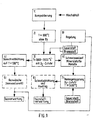
In Fig. 1 sind die Verfahrensschritte 1) bis 8) symbolisiert. Der Abfall wird ohne Vorbehandlung, d.h. ohne Sortierung und ohne Zerkleinerung, der Stufe 1) zugeführt, in der er kompaktiert wird. Hierbei wird das Kompaktierungsergebnis erheblich verbessert, wenn in vertikaler und in horizontaler Richtung Preßflächen wirken. Eine hohe Verdichtung ist notwendig, da die Beschickungsöffnung des Schubkanals, in dem die Verfahrensstufe 2) abläuft, durch den hochverdichteten Abfallpfropfen gasdicht verschlossen wird.The method steps 1) to 8) are symbolized in FIG. 1. The waste is processed without pretreatment, i.e. without sorting and without shredding, level 1) supplied in which it is compacted. Here will the compaction result improved significantly if pressing surfaces in the vertical and horizontal direction Act. A high compression is necessary because the feed opening of the push channel in which the Process stage 2) takes place through the highly compressed Waste plug is sealed gas-tight.
Der hochverdichtete Abfall durchläuft den Schubkanal der Stufe 2) unter Sauerstoffabschluß bei Temperaturen bis zu 600 °C. Organische Bestandteile des Abfalles werden entgast. Die Gase durchströmen die im Schubofen befindlichen Abfälle in Richtung der Verfahrensstufe 3). Sie tragen bei diesem Durchströmen ebenso zu einem guten Wärmeübergang bei wie der intensive Druckkontakt des Abfalles mit den Schubofenwänden. Infolge des stetigen Nachschiebens des hochverdichteten Abfalles bleibt dieser Druckkontakt über die ganze Ofenlänge und die Gesamtheit der Kanalflächen erhalten, so daß am Ende des Abfalldurchlaufes durch den Schubkanal die Entgasung der organischen Substanzen weitgehend abgeschlossen ist.The highly compressed waste runs through the push channel stage 2) with exclusion of oxygen at temperatures up to 600 ° C. Organic waste components are degassed. The gases flow through the Waste located in the direction of the process stage 3). They contribute to this flow as well as a good heat transfer as the intensive Pressure contact of the waste with the push furnace walls. As a result of the constant feeding of the highly compressed This pressure contact remains the entire length of the furnace and the entirety of the channel surfaces received so that at the end of the waste cycle degassing of the organic through the thrust channel Substances is largely complete.
Schwelgase, Wasserdampf, wie er aus der natürlichen Abfallfeuchte herrührt, Metalle, Mineralien und der Kohlenstoff der entgasten Organika werden gemeinsam der Verfahrensstufe 3) zugeführt, in der zunächst der Kohlenstoff mit Sauerstoff verbrannt wird. Die hierbei auftretenden Temperaturen von bis zu 2000 °C und mehr schmelzen die metallischen und mineralischen Bestandteile auf, so daß sie in dem Verfahrensschritt 6) schmelzflüssig ausgetragen werden können.Smoldering gases, water vapor as it comes from natural Waste moisture originates from metals, minerals and the Carbon from the degassed organics become common the process stage 3) supplied, in which the Carbon is burned with oxygen. The one here occurring temperatures of up to 2000 ° C and the metallic and mineral components melt more on so that in step 6) can be discharged molten.
Parallel dazu werden über dem Hochtemperaturbereich des glühenden Kohlenstoffbettes bei Temperaturen von mehr als 1200 °C die organischen Verbindungen der Schwelgase zerstört. Infolge der Reaktionsgleichgewichte von C, CO2, CO und H2O bei diesen Temperaturen bildet sich Synthesegas, im wesentlichen aus CO, H2 und CO2 bestehend, das im Verfahrensschritt 4) schockartig auf Temperaturen unter 100 °C abgekühlt wird. Die Schnellabkühlung verhindert die Neubildung von organischen Schadstoffen und erleichtert die in Stufe 5) vorgesehene Gaswäsche. Das hochreine Synthesegas steht danach zu beliebiger Verwendung zur Verfügung.At the same time, the organic compounds of the carbonization gases are destroyed over the high temperature range of the glowing carbon bed at temperatures of more than 1200 ° C. As a result of the reaction equilibria of C, CO 2 , CO and H 2 O at these temperatures, synthesis gas is formed, consisting essentially of CO, H 2 and CO 2 , which is suddenly cooled to below 100 ° C. in process step 4). The rapid cooling prevents the formation of new organic pollutants and facilitates the gas scrubbing provided in stage 5). The high-purity synthesis gas is then available for any use.
Das hochreine Synthesegas kann bei dem insoweit bekannten Verfahren einen von der Abfallzusammensetzung und Menge abhängigen Volumenstrom und auch eine variierende Konzentration an Wasserstoff aufweisen. Daher wird nach der Gaswäsche 5) der Wasserstoffgehalt des aufgereinigten Synthesegases bestimmt und diese Werte einer Regelung 9) zugeführt. Diese Regelung steuert nunmehr, wie oben beschrieben, die Zufuhr an Sauerstoff in die Verfahrensstufe 3), bei der der vorher entgaste Abfall bei Temperaturen von bis zu 2000 °C durch Zugabe von O2 vergast wird. Durch diese Änderung des der Sauerstoffzufuhr kann der Wasserstoffgehalt des entstehenden Synthesegases beeinflußt werden. Durch diese Regelung steht daher der Gasverwertung im Anschluß an die Gaswäsche 5) ein Synthesegasstrom mit geregeltem konstantem Wasserstoffgehalt zur Verfügung.In the process known to this extent, the high-purity synthesis gas can have a volume flow dependent on the waste composition and amount and also a varying concentration of hydrogen. Therefore, after the gas scrubbing 5), the hydrogen content of the purified synthesis gas is determined and these values are fed to a control 9). As described above, this regulation now controls the supply of oxygen to process stage 3), in which the previously degassed waste is gasified at temperatures of up to 2000 ° C. by adding O 2 . This change in the oxygen supply can influence the hydrogen content of the synthesis gas formed. This regulation therefore provides gas utilization following gas scrubbing 5) with a synthesis gas stream with a controlled constant hydrogen content.
Die im Verfahrensschritt 6) schmelzflüssig ausgetragenen Metalle und Mineralstoffe werden zweckmäßigerweise im Verfahrensschritt 7) einer Nachbehandlung unter Sauerstoffzufuhr bei mehr als 1400 °C unterzogen. Hierbei werden mitgeschleppte Kohlenstoffreste beseitigt und die Mineralisierung abgeschlossen. Der Austrag der Feststoffe, beispielsweise in ein Wasserbad, schließt im Verfahrensschritt 8) das Entsorgungsverfahren ab. In dem nach dem Austrag der Feststoffe in ein Wasserbad erhaltenem Granulat befinden sich Metalle und Legierungselemente und vollständig mineralisierte Nichtmetalle nebeneinander. Eisenlegierungen können magnetisch abgeschieden werden. Die auslaugungsfest mineralisierten Nichtmetalle können vielseitig wiederverwendet werden, beispielsweise in geblähter Granulatform oder - zu Steinwolle verarbeitet - als Isolierstoff oder direkt als Granulat für Füllstoffe im Straßenbau und bei der Betonherstellung. Those discharged in the molten state in process step 6) Metals and minerals are useful in process step 7) aftertreatment subjected to oxygen supply at more than 1400 ° C. This entails entrained carbon residues eliminated and mineralization completed. The Discharge of the solids, for example into a water bath, closes the disposal process in process step 8) from. In the after the discharge of the solids granules obtained in a water bath themselves metals and alloying elements and complete mineralized non-metals side by side. ferroalloys can be separated magnetically. The Leach-proof mineralized non-metals can can be reused in many ways, for example in expanded pellet form or - processed into rock wool - As an insulating material or directly as granules for Fillers in road construction and in the production of concrete.
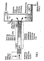
Fig. 2 zeigt eine stark schematisierte Darstellung einer Vorrichtung zur Durchführung des erfindungsgemäßen Verfahrens. Den einzelnen Bereichen sind typische Prozeßdaten einer beispielsweisen vorteilhaften Verfahrensdurchführung zugeordnet. Die Entgasung ist eine Funktion der Temperatur T, des Druckes und der Abfallzusammensetzung.Fig. 2 shows a highly schematic representation a device for performing the invention Process. The individual areas are typical Process data of an advantageous example Procedure implementation assigned. The degassing is a function of temperature T, pressure and Waste composition.
Die Zusammensetzung und der Volumenstrom hängt nunmehr vom vorhandenen Kohlenstoff, Sauerstoff und Wasserdampf ab. Indem über die Regelung die Menge an zur Verfügung stehendem Kohlenstoff (Brennstoffzufuhr zur Gasphase) und Sauerstoff (Sauerstoffzufuhr über Sauerstofflanzen in die Gasphase) gesteuert wird, wird die Zusammensetzung des Synthesegases, die bereits bei dem bekannten Verfahren eine relativ hohe Qualität besitzt, weiter optimiert und eignet sich daher ideal zur Verwendung z.B. in Gasmotoren zur Verstromung oder für chemische Prozesse.The composition and the volume flow now depend of the available carbon, oxygen and water vapor from. By regulating the amount of Available carbon (fuel supply for Gas phase) and oxygen (oxygen supply via oxygen lances is controlled in the gas phase) the composition of the synthesis gas that already a relatively high quality in the known method owns, further optimized and is therefore suitable ideal for use e.g. in gas engines for electricity generation or for chemical processes.
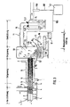
In Fig. 3 entspricht die Verdichtungspresse 1 in Ihrem
Aufbau einer an sich bekannten Schrottpresse, wie
sie z.B. für die Verschrottung von Fahrzeugen eingesetzt
wird. Die schwenkbare Preßplatte 2 ermöglicht
in senkrecht (gestrichelter) Darstellung das Beschikken
der Presse 1 mit Mischabfall. Die Preßfläche 3
befindet sich in linker Position, so daß der Beschikkungsraum
der Presse voll geöffnet ist. Durch das
Einschwenken der Preßplatte 2 in die dargestellte horizontale
Position wird der Abfall zunächst in vertikaler
Richtung verdichtet. Danach bewegt sich die
Preßfläche 3 horizontal in die in ausgezogener Linienführung
dargestellte Lage und verdichtet das Abfallpaket
in horizontaler Richtung. Die hierzu benötigten
Gegenkräfte werden durch die in Pfeilrichtung
aus- und einfahrbare Gegenplatte 9 aufgenommen. Nachdem
der Verdichtungsvorgang abgeschlossen ist, wird
die Gegenplatte 9 ausgefahren und der verdichtete Abfallpfropfen
mit Hilfe der sich nach rechts weiterbewegenden
Preßfläche 3 in den unbeheizten Bereich 5
des Schubofens 6 eingeschoben und so dessen Gesamtinhalt
entsprechend weitertransportiert, nachverdichtet
und mit der Kanal- bzw. Ofenwand in Druckkontakt gehalten.
Anschließend wird die Preßfläche 3 in die
linke Endposition zurückgefahren, die Gegenplatte 9
eingefahren und die Preßplatte 2 in die gestrichelt
dargestellte Vertikalposition zurückgeschwenkt. Die
Verdichtungspresse 1 ist für eine Neubeschickung bereit.
Die Abfallverdichtung ist so groß, daß der in
den unbeheizten Bereich 5 des Schubofens 6 eingeschobene
Abfallpfropfen gasdicht ist. Die Beheizung des
Schubofens erfolgt durch Flamm- und/oder Abgase, die
den Heizmantel 8 in Pfeilrichtung durchströmen.3 corresponds to the
Beim Durchschub des verdichteten Abfalles durch den
Ofenkanal 6 breitet sich die entgaste Zone 7 in der
dargestellten Weise zur Mittelebene des Schubofens 6
hin aus, begünstigt durch die mit dem Seiten/Höhen-Verhältnis
>2 seines Rechteckquerschnittes verbundene
große Oberfläche. Beim Eintritt in den Hochtemperaturreaktor
10 liegt ein durch ständige Druckbeaufschlagung
beim Durchschub kompaktiertes Gemisch von
Kohlenstoff, Mineralien und Metallen vor. Dieses Gemisch
wird im Bereich der Eintrittsöffnung in den
Hochtemperaturreaktor extrem großer Strahlungshitze
ausgesetzt. Die hiermit verbundene plötzliche Expansion
von Restgasen im Schwelgut führt zu dessen stükkiger
Zerteilung. Das so erhaltene Feststoff-Stückgut
bildet im Hochtemperaturreaktor ein gasdurchlässiges
Bett 20, in dem der Kohlenstoff des Schwelgutes mit
Hilfe von Sauerstofflanzen 12 zunächst zu CO2 bzw. When the compressed waste is pushed through the
CO verbrannt wird. Die oberhalb des Bettes 20 den Reaktor
10 verwirbelt durchströmenden Schwelgase werden
durch Cracken vollständig entgiftet. Zwischen C,
CO2, CO und dem aus dem Abfall ausgetriebenen Wässerdampf
stellt sich ein temperaturbedingtes Reaktionsgleichgewicht
bei der Synthesegasbildung ein. Die
sich ergebenden Temperaturen entsprechen der Darstellung
der Fig. 2. Das Synthesegas wird im Behälter 14
durch Wassereindüsung auf weniger als 100 °C schockartig
gekühlt. Im Gas mitgeschleppte Bestandteile
(Mineralien und/oder Metall in geschmolzenem Zustand)
werden im Kühlwasser abgeschieden, Wasserdampf kondensiert,
so daß sich das Gasvolumen verringert und
so die Gasreinigung erleichtert wird, die sich an die
Schockkühlung in an sich bekannten Anordnungen anschließen
kann. Das zur schockartigen Kühlung des
Synthesegasstromes verwendete Wasser kann gegebenenfalls
nach Aufreinigung wiederum zur Kühlung verwendet
werden.CO is burned. The smoldering gases flowing through the
Die Regelung des Wasserstoffgehaltes
erfolgt über eine in dem abgeleiteten Synthesegasstrom
angeordneten Sensor 100, der Signale über
eine Leitung 102 an eine Regelvorrichtung 101 weiterleitet.
Die Signale enthalten sowohl den aktuellen
Wasserstoffgehalt
des abgekühlten, gereinigten und abgeleiteten Synthesegasstromes.
Die Regelung verändert nun die mittels
der Steuersignalleitung 103, die zwischen der Steuerung
101 und einer Sauerstofflanze 104 angeordnet
ist, die Zufuhr von Sauerstoff durch die Sauerstofflanze
104 in die Gasphase über der Schüttung 20.
Durch eine Erhöhung der Sauerstoffzufuhr kann dabei
eine erhöhte Verbrennung von H2 und damit ein niedrigerer
Wasserstoffgehalt im Synthesegas erzeugt werden.
Durch eine Erniedrigung der Sauerstoffzufuhr
über die Sauerstofflanze 104 wird die Verbrennung in
der Gasphase verringert und damit steigt der Wasserstoffgehalt
in dem Synthesegas. Ist der Volumenstrom
des Synthesegases nicht ausreichend, so kann von der
Steuerung 101 auch die Zufuhr von Brenngasen, wie
beispielsweise Erdgas oder Synthesegas selbst in die
Schüttung 20 oder auch in die Gasphase vergrößert
oder verringert werden. Damit wird der Gehalt an Kohlenwasserstoffen
in dem Reaktor geändert und folglich
der Gesamtsynthesegas-Volumenstrom beeinflußt.The hydrogen content is regulated via a
In dem mehr als 2000 °C heißen Kernbereich des Bettes
20 werden die mineralischen und metallischen Bestandteile
des Schwelgutes aufgeschmolzen. Aufgrund der
unterschiedlichen Dichte überschichten sie sich dabei
und entmischen sich. Typische Legierungselemente des
Eisens, wie beispielsweise Chrom, Nickel und Kupfer,
bilden mit dem Eisen des Abfalles eine verhüttbare
Legierung, andere Metallverbindungen bzw. Aluminium
oxidieren und stabilisieren als Oxide die Mineralschmelze.In the core area of the bed, which is more than 2000 °
Die Schmelzen treten direkt in den Nachbehandlungsreaktor 16 ein, in dem sie in einer mit Hilfe der O2-Lanze 13 eingebrachten Sauerstoffatmosphäre, gegebenenfalls unterstützt durch nicht dargestellte Gasbrenner Temperaturen von mehr als 1400 °C ausgesetzt werden. Mitgeschleppte Kohlenstoffpartikel werden oxidiert, die Schmelze wird homogenisiert und in ihrer Viskosität erniedrigt.The melts enter directly into the aftertreatment reactor 16, in which they are exposed to temperatures of more than 1400 ° C. in an oxygen atmosphere introduced with the aid of the O 2 lance 13, optionally supported by gas burners (not shown). Carried carbon particles are oxidized, the melt is homogenized and its viscosity is reduced.
Bei ihrem gemeinsamen Austrag in das Wasserbad 17
granulieren Mineralstoff und Eisenschmelze getrennt
und können danach magnetisch sortiert werden. During their joint discharge into the
In Fig. 3 ist die Lage des Nachbehandlungsreaktors 16
aus Gründen der Übersichtlichkeit um 90° versetzt gezeichnet.
Dieser Reaktor 16 bildet mit dem Unterteil
des Hochtemperaturreaktors 10 eine Baueinheit, die
nach dem Lösen einer Flanschverbindung 10' zu Wartungs-
und Reparaturzwecken seitlich aus der Vorrichtungslinie
ausfahrbar ist.3 shows the position of the aftertreatment reactor 16
drawn at 90 ° for clarity.
This reactor 16 forms with the lower part
of the high-
Die in Fig. 3 dargestellte, im wesentlichen fluchtend
angeordnete Vorrichtungslinie erstreckt sich über eine
erhebliche Länge. Wechselnde Temperaturen - vor
allem beim An- und Herunterfahren der Anlage in das
und aus dem thermischen Gleichgewicht - führen zu erheblichen
Wärmedehnungen. Bei ortsfester Anordnung
des Hochtemperaturreaktors 10 wird dies für den
Schubofen 6 und die mit ihm verbundene Verdichtungspresse
1 durch die Rollen 4 berücksichtigt, die in
Führungsschienen laufend (nicht dargestellt), nicht
nur Längsbewegungen ermöglichen, sondern auch Seitenkräfte
aufnehmen können. Bei den vom Hochtemperaturreaktor
abgehenden Rohrleitungen (beispielsweise 15)
sorgen Faltenbälge 11 für den Dehnungsausgleich.3, essentially in alignment
arranged device line extends over a
considerable length. Changing temperatures - before
especially when starting up and shutting down the system in the
and out of thermal equilibrium - lead to considerable
Thermal expansion. With a fixed arrangement
of the
Claims (21)
- Method for disposal and utilisation of all kinds of waste products where unsorted, untreated industrial, domestic and/or special waste containing any harmful substance in solid and/or liquid form as well as industrial goods scrap are subjected to thermal separation or material conversion and obtained solid remnants are transferred into a high temperature furnace, and the disposed material is in charges compressed into compact packets and passed through temperature treatment stages in the direction of increasing temperature with at least one low temperature stage where, whilst maintaining the pressure application, a shape and positive contact to the walls of the reaction vessel is ensured, and with at least one high temperature zone where the disposed good forms a gas permeable bulk and synthetic gas is produced, and produced synthetic gas is diverted from the high temperature zone, characterised in that the concentration of hydrogen in the diverted synthetic gas is regulated so that the concentration of hydrogen in the diverted synthetic gas is regulated to a value which is seen as constant.
- Method according to Claim 1, characterised in that the hydrogen concentration in diverted synthetic gas is regulated to approximately 35 %-vol.
- Method according to one of the above claims, characterised in that in dependence of the hydrogen concentration in the diverted synthetic gas oxygen is additionally introduced into the high temperature stage.
- Method according to one of the above claim, characterised in that the oxygen is introduced into the high temperature stage via oxygen lances.
- Method according to one of the two above claims, characterised in that oxygen is introduced by way of pulses.
- Method according to one of the above claims, characterised in that in dependence of the volume flow fuel is additionally introduced into the high temperature stage.
- Method according to one of the above claims, characterised in that at least the low temperature stage is, whilst maintaining pressure in shape and positive contact with the walls of the reactor vessel, passed through to the exclusion of oxygen.
- Method according to one of the above claims, characterised in that the low temperature stage is passed through in a temperature range between 100°C and 600°C.
- Method according to one of the above claims, characterised in that the high temperature stage is passed through with added oxygen.
- Method according to the above claim, characterised in that carbon portions in the bulk are gasified by apportioned addition of oxygen to carbon dioxide and carbon monoxide, and carbon dioxide is, whilst passing through the carbon containing bulk, reduced to carbon monoxide, and hydrogen and carbon monoxide are produced from the carbon and highly heated water vapour.
- Method according to one of the above claims, characterised in that the high temperature stage is passed through at temperatures of more than 1,000°C.
- Method according to one of the above claims, characterised in that diverted synthetic gas is directly after departure from the high temperature reactor subjected to a shocklike water charge until cooled to below 100°C and dusted.
- Method according to one of the above claims, characterised in that the content of hydrogen is verified after shocklike cooling, and accordingly the hydrogen content of diverted synthetic gas is regulated.
- Device for material processing, conversion and final treatment of all types of waste products by way of a plurality of thermal treatment stages which include at least one low temperature stage under exclusion of oxygen and at least one high temperature stage under oxygen delivery at temperatures above 1,000°C, and with an outlet for a synthetic gas mixture generated in the high temperature stage, and all reaction areas of the treatment stages are free of locks and firmly connected to each other, and in the high temperature stage are provided devices for feeding oxygen and devices for feeding fuel, characterised in that at the synthetic gas mixture outlet are arranged sensors for determining the hydrogen content which are connected to a control device for the quantity of fed oxygen and/or fuel.
- Device according to the above claim, characterised in that the gas outlet side of the high temperature stage is connected to a rapid gas cooler which comprises a water injector for cold water into the hot stream of synthetic gas mixture.
- Device according to one of the two above claims, characterised in that the synthetic gas outlet comprises a throttle device, for example a controllable throttle flap.
- Device according to one of Claims 14 to 16, characterised in that upstream or downstream of the synthetic gas mixture outlet is arranged a device for gas purification.
- Device according to one of Claims 14 to 17, characterised in that downstream of the synthetic gas mixture is provided a device for gas utilisation, for example a gas motor/generator combination, a gas turbine, steam generator or the like.
- Device according to one of Claims 14 to 18, characterised in that the reaction area for the low temperature stage is a horizontally arranged, externally heated thrust furnace of rectangular cross-section, its ratio from furnace width to furnace height is greater than two, and the furnace length is given by the equation LFurnace ≥ 15 √FFurnace, with FFurnace as cross-sectional surface of the thrust furnace.
- Device according to one of Claims 14 to 19, characterised in that the reaction area for the high temperature stage is designed as a vertical shaft furnace wherein above its bottom the reaction area for the low temperature stage is continuously connected.
- Use of a device according to one of Claims 14 to 20, characterised in that, following synthetic gas separation or conditioning, hydrogen is used in hydrogen motors or fuel cells and/or synthetic gas is used for material use.
Applications Claiming Priority (3)
| Application Number | Priority Date | Filing Date | Title |
|---|---|---|---|
| DE19928581 | 1999-06-22 | ||
| DE19928581A DE19928581C2 (en) | 1999-06-22 | 1999-06-22 | Process and device for the disposal and utilization of waste goods |
| PCT/EP2000/005490 WO2000078896A1 (en) | 1999-06-22 | 2000-06-15 | Method and device for disposing of waste products |
Publications (2)
| Publication Number | Publication Date |
|---|---|
| EP1187891A1 EP1187891A1 (en) | 2002-03-20 |
| EP1187891B1 true EP1187891B1 (en) | 2003-05-07 |
Family
ID=7912155
Family Applications (1)
| Application Number | Title | Priority Date | Filing Date |
|---|---|---|---|
| EP00938791A Expired - Lifetime EP1187891B1 (en) | 1999-06-22 | 2000-06-15 | Method and device for disposing of waste products |
Country Status (9)
| Country | Link |
|---|---|
| EP (1) | EP1187891B1 (en) |
| JP (1) | JP4445175B2 (en) |
| KR (1) | KR100679781B1 (en) |
| AT (1) | ATE239775T1 (en) |
| AU (1) | AU777849B2 (en) |
| DE (2) | DE19928581C2 (en) |
| ES (1) | ES2195901T3 (en) |
| PT (1) | PT1187891E (en) |
| WO (1) | WO2000078896A1 (en) |
Cited By (1)
| Publication number | Priority date | Publication date | Assignee | Title |
|---|---|---|---|---|
| DE102006040770A1 (en) * | 2006-08-31 | 2008-03-13 | Thermoselect Ag | Process for the production of fuels from waste |
Families Citing this family (14)
| Publication number | Priority date | Publication date | Assignee | Title |
|---|---|---|---|---|
| EP1312662A3 (en) * | 2001-05-07 | 2003-09-24 | Cirad-Foret | Biomass gasification process, and apparatus, and their applications |
| KR100742271B1 (en) * | 2006-03-30 | 2007-07-24 | 고등기술연구원연구조합 | Quenching apparatus of a high-temperature reactor system |
| AU2007238126B2 (en) * | 2006-04-11 | 2013-08-15 | Thermo Technologies, Llc | Methods and apparatus for solid carbonaceous materials synthesis gas generation |
| JP5348516B2 (en) * | 2006-11-17 | 2013-11-20 | Jfeエンジニアリング株式会社 | Reforming control method for gasification reforming equipment |
| DE102007004221A1 (en) * | 2007-01-27 | 2008-09-25 | Robert Bosch Gmbh | Apparatus and method for the thermal conversion of pellets or wood chips |
| DE102007012452B4 (en) * | 2007-03-15 | 2014-01-16 | SynCraft Enegineering GmbH | carburettor |
| EP1992793B1 (en) * | 2007-05-14 | 2014-11-26 | Litesso-Anstalt | Method for generating electric power from waste products of all types |
| CZ2007553A3 (en) | 2007-08-16 | 2009-02-25 | Agro-Eko Spol. S R. O. | Method of and apparatus for pyrolytic conversion of combustible material |
| GR20080100220A (en) * | 2008-04-02 | 2009-11-19 | Method and devices of production of combustible gases. | |
| DE102008046820A1 (en) * | 2008-09-11 | 2010-03-25 | Uhde Gmbh | Plant for syngas production |
| EP2547751B1 (en) * | 2010-03-15 | 2018-07-18 | Rain Water, LLC | Gasification apparatus and method |
| GB2470127B (en) * | 2010-05-20 | 2011-03-23 | Rifat A Chalabi | Improvements in waste recycling |
| WO2012012823A1 (en) * | 2010-07-27 | 2012-02-02 | Curtin University Of Technology | A method of gasifying carbonaceous material and a gasification system |
| EP3029372A1 (en) * | 2014-12-04 | 2016-06-08 | Francesco Ianno | Plant and process for recovering energy from organic matrix waste material |
Family Cites Families (8)
| Publication number | Priority date | Publication date | Assignee | Title |
|---|---|---|---|---|
| DE2526947A1 (en) * | 1975-06-16 | 1976-12-30 | Karl Dipl Ing Kiener | Fuel gas prodn. from household or industrial waste - by reacting waste pyrolysis gases with incandescent coke |
| AR205469A1 (en) * | 1974-07-04 | 1976-05-07 | Kiener Karl | PROCEDURE AND DEVICE FOR OBTAINING COMBUSTIBLE GAS |
| GB2099843B (en) * | 1981-06-10 | 1985-01-30 | Texaco Development Corp | Partial oxidation process |
| DE4040377C1 (en) * | 1990-12-17 | 1992-02-06 | Thermoselect Ag, Vaduz, Li | |
| ATE146816T1 (en) * | 1991-06-18 | 1997-01-15 | Thermoselect Ag | METHOD FOR MAKING WASTE USABLE, WHICH WASTE IS THERMALLY TREATED AND SUBMITTED TO COMPLETE MATERIAL CONVERSION |
| DE4130416C1 (en) * | 1991-09-10 | 1992-12-10 | Thermoselect Ag, Vaduz, Li | |
| DE4311769C2 (en) * | 1993-04-08 | 1997-07-03 | Thermoselect Ag | Methods of removing and disposing of landfills |
| DE19750841A1 (en) * | 1996-11-28 | 1998-07-30 | Toms Elektrik Und Anlagenbau G | Two-stage gasification process for wastes containing organic materials |
-
1999
- 1999-06-22 DE DE19928581A patent/DE19928581C2/en not_active Expired - Fee Related
-
2000
- 2000-06-15 WO PCT/EP2000/005490 patent/WO2000078896A1/en active IP Right Grant
- 2000-06-15 JP JP2001505645A patent/JP4445175B2/en not_active Expired - Fee Related
- 2000-06-15 ES ES00938791T patent/ES2195901T3/en not_active Expired - Lifetime
- 2000-06-15 EP EP00938791A patent/EP1187891B1/en not_active Expired - Lifetime
- 2000-06-15 AT AT00938791T patent/ATE239775T1/en not_active IP Right Cessation
- 2000-06-15 DE DE50002089T patent/DE50002089D1/en not_active Expired - Lifetime
- 2000-06-15 KR KR1020017016456A patent/KR100679781B1/en not_active IP Right Cessation
- 2000-06-15 AU AU54050/00A patent/AU777849B2/en not_active Ceased
- 2000-06-15 PT PT00938791T patent/PT1187891E/en unknown
Cited By (1)
| Publication number | Priority date | Publication date | Assignee | Title |
|---|---|---|---|---|
| DE102006040770A1 (en) * | 2006-08-31 | 2008-03-13 | Thermoselect Ag | Process for the production of fuels from waste |
Also Published As
| Publication number | Publication date |
|---|---|
| KR20020012289A (en) | 2002-02-15 |
| AU5405000A (en) | 2001-01-09 |
| EP1187891A1 (en) | 2002-03-20 |
| AU777849B2 (en) | 2004-11-04 |
| JP4445175B2 (en) | 2010-04-07 |
| JP2003503171A (en) | 2003-01-28 |
| DE19928581A1 (en) | 2001-01-11 |
| DE50002089D1 (en) | 2003-06-12 |
| ATE239775T1 (en) | 2003-05-15 |
| ES2195901T3 (en) | 2003-12-16 |
| DE19928581C2 (en) | 2001-06-28 |
| WO2000078896A1 (en) | 2000-12-28 |
| KR100679781B1 (en) | 2007-02-07 |
| PT1187891E (en) | 2003-09-30 |
Similar Documents
| Publication | Publication Date | Title |
|---|---|---|
| AT402964B (en) | METHOD FOR THE USE OF DISPOSAL GOODS | |
| EP0443596B2 (en) | Pyrolysis process and apparatus for carrying out the process | |
| EP2082013B1 (en) | Method for producing a product gas rich in hydrogen | |
| DE4446803C2 (en) | Process and device for thermal and material recycling of residual and waste materials | |
| EP1187891B1 (en) | Method and device for disposing of waste products | |
| EP1252264B1 (en) | 2-stage cooling process for synthesis gas | |
| EP0520086B1 (en) | Process for the valorisation of all kinds of waste | |
| EP0897967A2 (en) | Process and apparatus for gasifying waste materials | |
| DE19522457C2 (en) | Process for treating household waste | |
| DE19949142C1 (en) | Process and device for the disposal and utilization of waste goods | |
| AT524123B1 (en) | Device for utilizing process gas with the conversion of old materials and the formation of synthesis gas | |
| EP1203060B1 (en) | Method and apparatus for utilizing gas from a sedimentation basin | |
| AT402552B (en) | METHOD FOR INTERMEDIATE STORAGE, TRANSPORT AND / OR ENERGY AND PERSONAL USE OF DISPOSAL OF ALL TYPES | |
| DE19536383A1 (en) | Gasification of low value fuels | |
| EP1323809B1 (en) | Co-current shaft reactor | |
| DE19513832B4 (en) | Process for recycling residual and waste materials by combining a fluidized-bed thermolysis with an entrainment gasification | |
| EP2148135B1 (en) | Method and device for thermal processing of waste material | |
| DE10158463B4 (en) | Process for the combined recycling of waste materials of different types, consistency and composition in a shaft-melting gasifier | |
| AT397808B (en) | METHOD FOR PRESSURE GASIFICATION OF ORGANIC SUBSTANCES, e.g. PLASTIC MIXTURES | |
| CZ286390B6 (en) | Apparatus for treating materials and method of neutralizing and reuse of waste materials | |
| SK282177B6 (en) | Device for material modification, method for disposal and utilization of scrap materials |
Legal Events
| Date | Code | Title | Description |
|---|---|---|---|
| PUAI | Public reference made under article 153(3) epc to a published international application that has entered the european phase |
Free format text: ORIGINAL CODE: 0009012 |
|
| 17P | Request for examination filed |
Effective date: 20011204 |
|
| AK | Designated contracting states |
Kind code of ref document: A1 Designated state(s): AT BE CH CY DE DK ES FI FR GB GR IE IT LI LU MC NL PT SE |
|
| AX | Request for extension of the european patent |
Free format text: AL;LT;LV;MK;RO;SI |
|
| 17Q | First examination report despatched |
Effective date: 20020405 |
|
| GRAH | Despatch of communication of intention to grant a patent |
Free format text: ORIGINAL CODE: EPIDOS IGRA |
|
| GRAH | Despatch of communication of intention to grant a patent |
Free format text: ORIGINAL CODE: EPIDOS IGRA |
|
| GRAA | (expected) grant |
Free format text: ORIGINAL CODE: 0009210 |
|
| AK | Designated contracting states |
Designated state(s): AT BE CH CY DE DK ES FI FR GB GR IE IT LI LU MC NL PT SE |
|
| PG25 | Lapsed in a contracting state [announced via postgrant information from national office to epo] |
Ref country code: NL Free format text: LAPSE BECAUSE OF FAILURE TO SUBMIT A TRANSLATION OF THE DESCRIPTION OR TO PAY THE FEE WITHIN THE PRESCRIBED TIME-LIMIT Effective date: 20030507 |
|
| REG | Reference to a national code |
Ref country code: GB Ref legal event code: FG4D Free format text: NOT ENGLISH |
|
| REG | Reference to a national code |
Ref country code: CH Ref legal event code: EP |
|
| GBT | Gb: translation of ep patent filed (gb section 77(6)(a)/1977) |
Effective date: 20030507 |
|
| REG | Reference to a national code |
Ref country code: IE Ref legal event code: FG4D Free format text: GERMAN |
|
| REF | Corresponds to: |
Ref document number: 50002089 Country of ref document: DE Date of ref document: 20030612 Kind code of ref document: P |
|
| PG25 | Lapsed in a contracting state [announced via postgrant information from national office to epo] |
Ref country code: LU Free format text: LAPSE BECAUSE OF NON-PAYMENT OF DUE FEES Effective date: 20030615 Ref country code: CY Free format text: LAPSE BECAUSE OF FAILURE TO SUBMIT A TRANSLATION OF THE DESCRIPTION OR TO PAY THE FEE WITHIN THE PRESCRIBED TIME-LIMIT Effective date: 20030615 Ref country code: AT Free format text: LAPSE BECAUSE OF NON-PAYMENT OF DUE FEES Effective date: 20030615 |
|
| PG25 | Lapsed in a contracting state [announced via postgrant information from national office to epo] |
Ref country code: MC Free format text: LAPSE BECAUSE OF NON-PAYMENT OF DUE FEES Effective date: 20030630 |
|
| PG25 | Lapsed in a contracting state [announced via postgrant information from national office to epo] |
Ref country code: DK Free format text: LAPSE BECAUSE OF FAILURE TO SUBMIT A TRANSLATION OF THE DESCRIPTION OR TO PAY THE FEE WITHIN THE PRESCRIBED TIME-LIMIT Effective date: 20030807 Ref country code: SE Free format text: LAPSE BECAUSE OF FAILURE TO SUBMIT A TRANSLATION OF THE DESCRIPTION OR TO PAY THE FEE WITHIN THE PRESCRIBED TIME-LIMIT Effective date: 20030807 |
|
| REG | Reference to a national code |
Ref country code: GR Ref legal event code: EP Ref document number: 20030402959 Country of ref document: GR |
|
| REG | Reference to a national code |
Ref country code: PT Ref legal event code: SC4A Free format text: AVAILABILITY OF NATIONAL TRANSLATION Effective date: 20030805 |
|
| NLV1 | Nl: lapsed or annulled due to failure to fulfill the requirements of art. 29p and 29m of the patents act | ||
| LTIE | Lt: invalidation of european patent or patent extension |
Effective date: 20030507 |
|
| REG | Reference to a national code |
Ref country code: ES Ref legal event code: FG2A Ref document number: 2195901 Country of ref document: ES Kind code of ref document: T3 |
|
| BERE | Be: lapsed |
Owner name: *THERMOSELECT A.G. Effective date: 20030630 |
|
| ET | Fr: translation filed | ||
| PLBE | No opposition filed within time limit |
Free format text: ORIGINAL CODE: 0009261 |
|
| STAA | Information on the status of an ep patent application or granted ep patent |
Free format text: STATUS: NO OPPOSITION FILED WITHIN TIME LIMIT |
|
| 26N | No opposition filed |
Effective date: 20040210 |
|
| REG | Reference to a national code |
Ref country code: CH Ref legal event code: NV Representative=s name: TROESCH SCHEIDEGGER WERNER AG |
|
| PG25 | Lapsed in a contracting state [announced via postgrant information from national office to epo] |
Ref country code: BE Free format text: LAPSE BECAUSE OF NON-PAYMENT OF DUE FEES Effective date: 20030630 |
|
| PGFP | Annual fee paid to national office [announced via postgrant information from national office to epo] |
Ref country code: PT Payment date: 20110614 Year of fee payment: 12 Ref country code: GR Payment date: 20110624 Year of fee payment: 12 Ref country code: IE Payment date: 20110621 Year of fee payment: 12 |
|
| PGFP | Annual fee paid to national office [announced via postgrant information from national office to epo] |
Ref country code: FI Payment date: 20110613 Year of fee payment: 12 |
|
| REG | Reference to a national code |
Ref country code: PT Ref legal event code: MM4A Free format text: LAPSE DUE TO NON-PAYMENT OF FEES Effective date: 20121217 |
|
| PGFP | Annual fee paid to national office [announced via postgrant information from national office to epo] |
Ref country code: ES Payment date: 20120627 Year of fee payment: 13 |
|
| PG25 | Lapsed in a contracting state [announced via postgrant information from national office to epo] |
Ref country code: FI Free format text: LAPSE BECAUSE OF NON-PAYMENT OF DUE FEES Effective date: 20120615 |
|
| PG25 | Lapsed in a contracting state [announced via postgrant information from national office to epo] |
Ref country code: PT Free format text: LAPSE BECAUSE OF NON-PAYMENT OF DUE FEES Effective date: 20121217 |
|
| REG | Reference to a national code |
Ref country code: GR Ref legal event code: ML Ref document number: 20030402959 Country of ref document: GR Effective date: 20130104 |
|
| REG | Reference to a national code |
Ref country code: IE Ref legal event code: MM4A |
|
| PG25 | Lapsed in a contracting state [announced via postgrant information from national office to epo] |
Ref country code: IE Free format text: LAPSE BECAUSE OF NON-PAYMENT OF DUE FEES Effective date: 20120615 |
|
| PG25 | Lapsed in a contracting state [announced via postgrant information from national office to epo] |
Ref country code: GR Free format text: LAPSE BECAUSE OF NON-PAYMENT OF DUE FEES Effective date: 20130104 |
|
| PGFP | Annual fee paid to national office [announced via postgrant information from national office to epo] |
Ref country code: CH Payment date: 20130621 Year of fee payment: 14 |
|
| PGFP | Annual fee paid to national office [announced via postgrant information from national office to epo] |
Ref country code: IT Payment date: 20140624 Year of fee payment: 15 |
|
| REG | Reference to a national code |
Ref country code: ES Ref legal event code: FD2A Effective date: 20141015 |
|
| PGFP | Annual fee paid to national office [announced via postgrant information from national office to epo] |
Ref country code: FR Payment date: 20140619 Year of fee payment: 15 |
|
| PG25 | Lapsed in a contracting state [announced via postgrant information from national office to epo] |
Ref country code: ES Free format text: LAPSE BECAUSE OF NON-PAYMENT OF DUE FEES Effective date: 20130616 |
|
| REG | Reference to a national code |
Ref country code: CH Ref legal event code: PL |
|
| PG25 | Lapsed in a contracting state [announced via postgrant information from national office to epo] |
Ref country code: CH Free format text: LAPSE BECAUSE OF NON-PAYMENT OF DUE FEES Effective date: 20140630 Ref country code: LI Free format text: LAPSE BECAUSE OF NON-PAYMENT OF DUE FEES Effective date: 20140630 |
|
| PG25 | Lapsed in a contracting state [announced via postgrant information from national office to epo] |
Ref country code: IT Free format text: LAPSE BECAUSE OF NON-PAYMENT OF DUE FEES Effective date: 20150615 |
|
| REG | Reference to a national code |
Ref country code: FR Ref legal event code: ST Effective date: 20160229 |
|
| PG25 | Lapsed in a contracting state [announced via postgrant information from national office to epo] |
Ref country code: FR Free format text: LAPSE BECAUSE OF NON-PAYMENT OF DUE FEES Effective date: 20150630 |
|
| PGFP | Annual fee paid to national office [announced via postgrant information from national office to epo] |
Ref country code: GB Payment date: 20160621 Year of fee payment: 17 |
|
| PGFP | Annual fee paid to national office [announced via postgrant information from national office to epo] |
Ref country code: DE Payment date: 20160630 Year of fee payment: 17 |
|
| REG | Reference to a national code |
Ref country code: DE Ref legal event code: R119 Ref document number: 50002089 Country of ref document: DE |
|
| GBPC | Gb: european patent ceased through non-payment of renewal fee |
Effective date: 20170615 |
|
| PG25 | Lapsed in a contracting state [announced via postgrant information from national office to epo] |
Ref country code: DE Free format text: LAPSE BECAUSE OF NON-PAYMENT OF DUE FEES Effective date: 20180103 Ref country code: GB Free format text: LAPSE BECAUSE OF NON-PAYMENT OF DUE FEES Effective date: 20170615 |