EP1187760B1 - Propelling and driving system for boats - Google Patents
Propelling and driving system for boats Download PDFInfo
- Publication number
- EP1187760B1 EP1187760B1 EP00947825A EP00947825A EP1187760B1 EP 1187760 B1 EP1187760 B1 EP 1187760B1 EP 00947825 A EP00947825 A EP 00947825A EP 00947825 A EP00947825 A EP 00947825A EP 1187760 B1 EP1187760 B1 EP 1187760B1
- Authority
- EP
- European Patent Office
- Prior art keywords
- drive
- control
- propulsion system
- rotation speed
- speed
- Prior art date
- Legal status (The legal status is an assumption and is not a legal conclusion. Google has not performed a legal analysis and makes no representation as to the accuracy of the status listed.)
- Expired - Lifetime
Links
- 230000001360 synchronised effect Effects 0.000 claims abstract description 31
- 238000004804 winding Methods 0.000 claims abstract description 14
- 230000001105 regulatory effect Effects 0.000 claims abstract description 11
- 230000003044 adaptive effect Effects 0.000 claims description 41
- 230000008859 change Effects 0.000 claims description 27
- 230000033228 biological regulation Effects 0.000 claims description 20
- 230000000712 assembly Effects 0.000 claims description 6
- 238000000429 assembly Methods 0.000 claims description 6
- 230000005540 biological transmission Effects 0.000 claims description 6
- 230000001419 dependent effect Effects 0.000 claims description 6
- 238000004891 communication Methods 0.000 claims description 5
- 238000013016 damping Methods 0.000 claims description 4
- 238000012544 monitoring process Methods 0.000 claims description 4
- 238000009826 distribution Methods 0.000 claims description 3
- 238000012806 monitoring device Methods 0.000 claims description 3
- 230000003213 activating effect Effects 0.000 claims description 2
- 230000010355 oscillation Effects 0.000 claims description 2
- 241001484259 Lacuna Species 0.000 claims 1
- 230000007547 defect Effects 0.000 claims 1
- 238000010248 power generation Methods 0.000 claims 1
- 230000001276 controlling effect Effects 0.000 abstract description 2
- 230000006870 function Effects 0.000 description 44
- 230000009467 reduction Effects 0.000 description 25
- 238000003825 pressing Methods 0.000 description 23
- 241000196324 Embryophyta Species 0.000 description 16
- 230000001133 acceleration Effects 0.000 description 16
- 230000000694 effects Effects 0.000 description 12
- 230000002829 reductive effect Effects 0.000 description 11
- 230000001965 increasing effect Effects 0.000 description 10
- 241000380131 Ammophila arenaria Species 0.000 description 9
- 230000000670 limiting effect Effects 0.000 description 9
- 230000003068 static effect Effects 0.000 description 9
- 239000000498 cooling water Substances 0.000 description 7
- 238000010586 diagram Methods 0.000 description 7
- 230000002123 temporal effect Effects 0.000 description 7
- 230000000977 initiatory effect Effects 0.000 description 6
- 238000004519 manufacturing process Methods 0.000 description 6
- 238000000034 method Methods 0.000 description 6
- 230000011664 signaling Effects 0.000 description 6
- 238000013461 design Methods 0.000 description 5
- 238000012546 transfer Methods 0.000 description 5
- 230000008901 benefit Effects 0.000 description 4
- 238000001816 cooling Methods 0.000 description 4
- 230000007423 decrease Effects 0.000 description 4
- 238000001514 detection method Methods 0.000 description 4
- 238000012423 maintenance Methods 0.000 description 4
- 238000007726 management method Methods 0.000 description 4
- 230000036961 partial effect Effects 0.000 description 4
- 230000001681 protective effect Effects 0.000 description 4
- XLYOFNOQVPJJNP-UHFFFAOYSA-N water Substances O XLYOFNOQVPJJNP-UHFFFAOYSA-N 0.000 description 4
- 241001202218 Semanotus undatus Species 0.000 description 3
- 238000006243 chemical reaction Methods 0.000 description 3
- 238000010276 construction Methods 0.000 description 3
- 238000011161 development Methods 0.000 description 3
- 230000018109 developmental process Effects 0.000 description 3
- 238000005516 engineering process Methods 0.000 description 3
- 230000005284 excitation Effects 0.000 description 3
- 239000000446 fuel Substances 0.000 description 3
- 239000007789 gas Substances 0.000 description 3
- 239000010720 hydraulic oil Substances 0.000 description 3
- 230000002441 reversible effect Effects 0.000 description 3
- IJGRMHOSHXDMSA-UHFFFAOYSA-N Atomic nitrogen Chemical compound N#N IJGRMHOSHXDMSA-UHFFFAOYSA-N 0.000 description 2
- 208000012886 Vertigo Diseases 0.000 description 2
- 230000006978 adaptation Effects 0.000 description 2
- 238000004378 air conditioning Methods 0.000 description 2
- 238000004873 anchoring Methods 0.000 description 2
- 230000015572 biosynthetic process Effects 0.000 description 2
- 230000004397 blinking Effects 0.000 description 2
- 238000002485 combustion reaction Methods 0.000 description 2
- 230000003111 delayed effect Effects 0.000 description 2
- 239000013505 freshwater Substances 0.000 description 2
- 238000009434 installation Methods 0.000 description 2
- 230000033001 locomotion Effects 0.000 description 2
- 230000003287 optical effect Effects 0.000 description 2
- 238000002360 preparation method Methods 0.000 description 2
- 230000008569 process Effects 0.000 description 2
- 230000000630 rising effect Effects 0.000 description 2
- 239000004065 semiconductor Substances 0.000 description 2
- 239000007858 starting material Substances 0.000 description 2
- 238000012360 testing method Methods 0.000 description 2
- 230000007704 transition Effects 0.000 description 2
- 230000001960 triggered effect Effects 0.000 description 2
- 241001136792 Alle Species 0.000 description 1
- 206010010219 Compulsions Diseases 0.000 description 1
- 101100437784 Drosophila melanogaster bocks gene Proteins 0.000 description 1
- 229910000831 Steel Inorganic materials 0.000 description 1
- 230000009471 action Effects 0.000 description 1
- 230000004913 activation Effects 0.000 description 1
- 239000000654 additive Substances 0.000 description 1
- 230000000996 additive effect Effects 0.000 description 1
- 230000032683 aging Effects 0.000 description 1
- 238000010009 beating Methods 0.000 description 1
- 230000009286 beneficial effect Effects 0.000 description 1
- 239000003990 capacitor Substances 0.000 description 1
- 239000004020 conductor Substances 0.000 description 1
- 238000012790 confirmation Methods 0.000 description 1
- 238000012937 correction Methods 0.000 description 1
- 230000008878 coupling Effects 0.000 description 1
- 238000010168 coupling process Methods 0.000 description 1
- 238000005859 coupling reaction Methods 0.000 description 1
- 230000003247 decreasing effect Effects 0.000 description 1
- 230000000994 depressogenic effect Effects 0.000 description 1
- 230000001627 detrimental effect Effects 0.000 description 1
- 238000005265 energy consumption Methods 0.000 description 1
- 238000004146 energy storage Methods 0.000 description 1
- 230000007613 environmental effect Effects 0.000 description 1
- 238000011156 evaluation Methods 0.000 description 1
- 230000000763 evoking effect Effects 0.000 description 1
- 230000004907 flux Effects 0.000 description 1
- 239000006260 foam Substances 0.000 description 1
- 239000000295 fuel oil Substances 0.000 description 1
- 238000009499 grossing Methods 0.000 description 1
- 230000003760 hair shine Effects 0.000 description 1
- 238000010438 heat treatment Methods 0.000 description 1
- 230000001771 impaired effect Effects 0.000 description 1
- 238000003780 insertion Methods 0.000 description 1
- 230000037431 insertion Effects 0.000 description 1
- 238000005259 measurement Methods 0.000 description 1
- 239000012528 membrane Substances 0.000 description 1
- 229910052757 nitrogen Inorganic materials 0.000 description 1
- 238000013439 planning Methods 0.000 description 1
- 238000005086 pumping Methods 0.000 description 1
- 238000012887 quadratic function Methods 0.000 description 1
- 238000011160 research Methods 0.000 description 1
- 238000009987 spinning Methods 0.000 description 1
- 239000010959 steel Substances 0.000 description 1
- 230000000638 stimulation Effects 0.000 description 1
- 238000012549 training Methods 0.000 description 1
- 238000012384 transportation and delivery Methods 0.000 description 1
- 238000012795 verification Methods 0.000 description 1
Images


Classifications
-
- B—PERFORMING OPERATIONS; TRANSPORTING
- B63—SHIPS OR OTHER WATERBORNE VESSELS; RELATED EQUIPMENT
- B63B—SHIPS OR OTHER WATERBORNE VESSELS; EQUIPMENT FOR SHIPPING
- B63B1/00—Hydrodynamic or hydrostatic features of hulls or of hydrofoils
- B63B1/02—Hydrodynamic or hydrostatic features of hulls or of hydrofoils deriving lift mainly from water displacement
- B63B1/04—Hydrodynamic or hydrostatic features of hulls or of hydrofoils deriving lift mainly from water displacement with single hull
- B63B1/042—Hydrodynamic or hydrostatic features of hulls or of hydrofoils deriving lift mainly from water displacement with single hull the underpart of which being partly provided with channels or the like, e.g. catamaran shaped
-
- B—PERFORMING OPERATIONS; TRANSPORTING
- B63—SHIPS OR OTHER WATERBORNE VESSELS; RELATED EQUIPMENT
- B63H—MARINE PROPULSION OR STEERING
- B63H1/00—Propulsive elements directly acting on water
- B63H1/02—Propulsive elements directly acting on water of rotary type
- B63H1/12—Propulsive elements directly acting on water of rotary type with rotation axis substantially in propulsive direction
-
- B—PERFORMING OPERATIONS; TRANSPORTING
- B63—SHIPS OR OTHER WATERBORNE VESSELS; RELATED EQUIPMENT
- B63H—MARINE PROPULSION OR STEERING
- B63H21/00—Use of propulsion power plant or units on vessels
- B63H21/22—Use of propulsion power plant or units on vessels the propulsion power units being controlled from exterior of engine room, e.g. from navigation bridge; Arrangements of order telegraphs
-
- B—PERFORMING OPERATIONS; TRANSPORTING
- B63—SHIPS OR OTHER WATERBORNE VESSELS; RELATED EQUIPMENT
- B63H—MARINE PROPULSION OR STEERING
- B63H23/00—Transmitting power from propulsion power plant to propulsive elements
- B63H23/22—Transmitting power from propulsion power plant to propulsive elements with non-mechanical gearing
- B63H23/24—Transmitting power from propulsion power plant to propulsive elements with non-mechanical gearing electric
-
- B—PERFORMING OPERATIONS; TRANSPORTING
- B63—SHIPS OR OTHER WATERBORNE VESSELS; RELATED EQUIPMENT
- B63H—MARINE PROPULSION OR STEERING
- B63H25/00—Steering; Slowing-down otherwise than by use of propulsive elements; Dynamic anchoring, i.e. positioning vessels by means of main or auxiliary propulsive elements
- B63H25/50—Slowing-down means not otherwise provided for
-
- B—PERFORMING OPERATIONS; TRANSPORTING
- B63—SHIPS OR OTHER WATERBORNE VESSELS; RELATED EQUIPMENT
- B63H—MARINE PROPULSION OR STEERING
- B63H5/00—Arrangements on vessels of propulsion elements directly acting on water
- B63H5/07—Arrangements on vessels of propulsion elements directly acting on water of propellers
- B63H5/08—Arrangements on vessels of propulsion elements directly acting on water of propellers of more than one propeller
-
- B—PERFORMING OPERATIONS; TRANSPORTING
- B63—SHIPS OR OTHER WATERBORNE VESSELS; RELATED EQUIPMENT
- B63H—MARINE PROPULSION OR STEERING
- B63H5/00—Arrangements on vessels of propulsion elements directly acting on water
- B63H5/07—Arrangements on vessels of propulsion elements directly acting on water of propellers
- B63H5/125—Arrangements on vessels of propulsion elements directly acting on water of propellers movably mounted with respect to hull, e.g. adjustable in direction, e.g. podded azimuthing thrusters
-
- B—PERFORMING OPERATIONS; TRANSPORTING
- B63—SHIPS OR OTHER WATERBORNE VESSELS; RELATED EQUIPMENT
- B63H—MARINE PROPULSION OR STEERING
- B63H5/00—Arrangements on vessels of propulsion elements directly acting on water
- B63H5/07—Arrangements on vessels of propulsion elements directly acting on water of propellers
- B63H5/16—Arrangements on vessels of propulsion elements directly acting on water of propellers characterised by being mounted in recesses; with stationary water-guiding elements; Means to prevent fouling of the propeller, e.g. guards, cages or screens
-
- B—PERFORMING OPERATIONS; TRANSPORTING
- B63—SHIPS OR OTHER WATERBORNE VESSELS; RELATED EQUIPMENT
- B63H—MARINE PROPULSION OR STEERING
- B63H5/00—Arrangements on vessels of propulsion elements directly acting on water
- B63H5/07—Arrangements on vessels of propulsion elements directly acting on water of propellers
- B63H5/125—Arrangements on vessels of propulsion elements directly acting on water of propellers movably mounted with respect to hull, e.g. adjustable in direction, e.g. podded azimuthing thrusters
- B63H2005/1254—Podded azimuthing thrusters, i.e. podded thruster units arranged inboard for rotation about vertical axis
- B63H2005/1258—Podded azimuthing thrusters, i.e. podded thruster units arranged inboard for rotation about vertical axis with electric power transmission to propellers, i.e. with integrated electric propeller motors
-
- B—PERFORMING OPERATIONS; TRANSPORTING
- B63—SHIPS OR OTHER WATERBORNE VESSELS; RELATED EQUIPMENT
- B63H—MARINE PROPULSION OR STEERING
- B63H5/00—Arrangements on vessels of propulsion elements directly acting on water
- B63H5/07—Arrangements on vessels of propulsion elements directly acting on water of propellers
- B63H5/08—Arrangements on vessels of propulsion elements directly acting on water of propellers of more than one propeller
- B63H5/10—Arrangements on vessels of propulsion elements directly acting on water of propellers of more than one propeller of coaxial type, e.g. of counter-rotative type
Definitions
- the invention relates to a drive and drive system for Ships according to the preamble of claim 1 or preamble of claim 2;
- a drive and Driving system is e.g. by the publication "Siemens Schottel Propulsor (SSP).
- SSP The podded electric drive with permanent excited motor ", SIEMENS-SCHOTTEL, March 1997 (1997-03), XP000198528 known.
- SSP known drive technology is one rotatable marine propulsion, preferably in the area of Rear of a ship is arranged and at the same time the functions Drive, rudder and transverse thrust generation met.
- the SSP drive is also characterized by a low ship resistance in the most diverse hulls and needs no additional cooling, as this by the drive motor causes water flowing around in the propulsion module becomes.
- the present invention is based on the object starting from the above-mentioned prior art, a drive and To create a driving system for ships with which a comparatively high safety with regard to a reliable Maneuverability of a ship on relative achieve cost-effective manner.
- control and regulating device contributes from standardized assemblies to a relative inexpensive production.
- both subsystems are parallel are operable, one of the control and regulating device the subsystems can be used as master and the other as slave is. Due to the parallel operation of the two subsystems results in an active redundancy of the drive system, while on the other by the master-slave arrangement the control and regulating a parent Control is ensured for both subsystems. On In this way it is possible that certain tasks, such as the speed control, exclusively by the master Control and taken over and for the are locked as slave used.
- each subsystem has a programmable logic Safety device is assigned, the In addition to alarm signals automatic control and control signals generated.
- control and control signals can For example, the engine speed or the stator current immediately be reduced if a fault in one of Subsystems is detected.
- each power converter a phase current control on.
- the phase current control as a transvector preceded by field-oriented regulation, to give the drive a high degree of dynamics.
- the task the transvector control consists of the Actual values of the stator voltage, stator currents and the pole wheel position the synchronous machine the position of the magnetic flux to determine, with the setpoint of the torque-forming St Sstroms set perpendicular to the determined flow axis becomes.
- a monitoring device is provided by which the energy production and distribution in the electrical system against an overload can be protected by the drive motor. This ensures that the setpoint limits the speed when the power demanded by the given set point of the propeller the available electric power in Wiring of the ship exceeds. Moreover, it is possible to specify a changed setpoint in the event of faults in the vehicle electrical system to overload the power generator sets and thus to avoid a "black out" in the electrical system.
- the individual components of the drive and drive system arranged in at least one prefabricated container.
- This offers the possibility of independent of the drive system Construction site of the ship largely to cable and on his Function to check out.
- There a wiring of the individual components of the drive system is dispensable on the shipyard, is eliminated also the logistic registration of the individual components on the Shipyard, resulting in a simpler and more clear logistical Planning results.
- it can be based on this A flexible delivery and thus an optimal Reach the time of installation of the container. Due to a single foundation for the container instead of various foundations for the individual components is also a lesser and therefore less expensive manufacturing effort ensured.
- This may preferably be a Act GPS unit.
- This will enable using GPS systems determine the exact location of a container. Thereby the way of the container from the loading over the Transportation to be checked to destination. It offer for example. the use of existing GPS systems, e.g. the IN-MAR-SAT system already used in the maritime sector. Due to the design can easily ensure that the appropriate containers are up get the right way to the right destination.
- the GPS units as removable Units on the container, for example, consisting of units from transmitter, power supply and the like, may upon arrival the container at the right place the unit to the container removed and used again.
- This fluctuating load moment is from the speed controller or this subordinate Current regulator retraced to the speed of the Propeller as accurate as possible at the preselected To keep the speed setpoint constant.
- the resulting vibrations are not only annoying for the ship's crew, but they also bring a significant Load for the entire construction of the ship with themselves, and should therefore be avoided.
- Hydromechanically seen is the load on the ship propeller described with his Nachstromfeld.
- the variation of this Strain caused by the skeg present on the hull or Wellenbock is shown again in the inhomogeneity the Nachstromfeldes of the propeller, which itself again in a fluctuating rate of progress in circulation of the propeller blade.
- a variation in the rate of progress of Propeller reduces the cavitation safety of a propeller, because at the same time the working point of a propeller of his Approaching or exceeding the cavitation limit.
- the working point of the propeller can limit the cavitation reach or exceed and thus a cavitation which then cause significant damage to the ship and especially on the propeller.
- a cavitation also leads to impermissible pressure fluctuations and noises, in particular the utility of passenger, research and military ships significantly reduced.
- the invention provides in the context of Drive and driving system before that the control device for Vibration damping of a variable speed drive independent on the number of motors working on a shaft only provides a single speed controller, with the output signal the speed controller returned to the controller input is. Since the output signal of the speed controller approximately proportionally to that delivered by the drive Torque is, so it can when an activation of the same with a suitable phase to the actual speed value a certain insensitivity for torque fluctuations brought about become.
- this effect has the essential Advantage that the speed of the propeller is no longer accurate remains constant but is subject to fluctuations which due to the changing loads on the propeller be caused; This is the result of the hydromechanical Coupling of the Nachstromfeldes with the progress rate resulting fluctuation range reduced.
- This reduction the fluctuation margin of the progress rate arises in that the fluctuation of the load on the propeller blade, which in the inhomogeneous Nachstromfeld of am Hull existing skegs or wavebocks, due to the above effect of the invention to a change in the speed that leads by their direction and size of their Cause counteracts and thus to a damping of Fluctuation of the rate of progress of the propeller blade leads, which in terms of cavitation most at risk is.
- the recycled Output signal of the speed controller multiplied by a factor becomes.
- this feedback should not be too be chosen strongly because otherwise by the also fed back, approximately constant mean value of the drive torque a strong reduction of the speed setpoint occurred and thereby the speed controller itself in a realization of the same with PI characteristic no longer in the position would be, the drive shaft to the set speed setpoint to accelerate.
- both for the controller input signal as well as for the output of a predetermined Voltage range is available, for example. -10 V to +10 V, where the limits are each the maximum speed in forward and reverse drive correspond to or maximum motor torque, so is for the setting of a optimal level of feedback a multiplicative adjustment these two signal levels are essential.
- the multiplication factor is between 0.01% and 3%, preferably between 0.1% and 2.0%, in particular between 0.15% and 1.5%. It is a natural very low feedback because - as mentioned above - already much of the changing load requested energy from the moment of inertia of the rotor received by the electric motor, the propeller and the drive shaft and can be returned to each of these.
- a certain degree of freedom for Speed variations is granted, so can the powertrain advantageous to use as energy storage, the similar to the backup capacitor with a power supply too a smoothing of the energy consumption from the electrical supply network the drive system contributes. Therefore, lead here a slight feedback on the remarkable result, that applied by the drive motor torque is smoothed to a large extent, without this resulting in a significant, permanent control deviation from the preselected setpoint would cause.
- the static Control deviation compensated by a corrected setpoint becomes. Since the static control deviation in the inventive Control loop structure is calculable, so it can through a correction circuit are largely compensated.
- a compensation method preferred by the invention is used the estimated mean load of the drive as Output size and tries by mathematical acquisition of the Distance parameter from this the expected, static control deviation to determine and by a corresponding, opposing Adjustment of the speed setpoint to compensate.
- the route has at least Nutritionally known properties, in particular results the static, mean load moment according to a Characteristic curve from the static actual speed value.
- the drive torque increases approximately quadratically with the actual speed value. If the actual speed value should therefore correspond to a specific speed setpoint, so can from this characteristic approximately the torque determined which are approximately proportional in the static state to the controller output signal, so that also the Mean value of the feedback signal and thus the remaining one Control deviation determined. By doing so is added to the (ideal) set point, preferably additive, this results when the predicted control deviation occurs as speed actual value just the ideal Speed setpoint.
- the speed controller have a PI characteristic. This results in stationary an extremely high stability of the stationary speed actual value, thanks largely to the predistortion according to the invention coincides with the ideal speed setpoint.
- the output from the speed controller corresponding control devices of drive and driving systems is the setpoint of a Current controller of the converter or converter and may not Change faster than the electrical system of the drive device of the ship's propeller can follow dynamically.
- the dynamic Limits to load changes in the electrical system depend on the diesel generators the diesel generator plant off.
- Inverters with control reactive power e.g. Current-source, Direct converter, DC converter for DC machines and the like, require a load-dependent reactive power.
- This reactive power is provided by the excitation of the synchronous generators delivered to the diesel generator plant.
- the temporal Gradient of load-dependent reactive power from the above mentioned converters with control reactive power is in drive equipment for ship propellers about 15 to 25 times faster than the excitement of the synchronous generators of the diesel generator plant can follow.
- the invention is therefore also the object of the further develop the drive and driving system mentioned at the outset, that the electric propeller motor accelerates, delayed or electrically braked without it while in the electrical system or in the area of the diesel generator system to come from fast load changes resulting problems can.
- a minimum high and a minimum return time specified by the permissible temporal change of the reactive power output of synchronous generators the diesel generator system feeding the vehicle electrical system are dependent.
- Propulsion device for ship propellers is the high and the return time of the adaptive ramp function generator for the current setpoint of the current controller depending on the operating state the diesel power system feeding the vehicle electrical system with electrical energy changeable, with different diesel generators the diesel generator plant in different Operating conditions can be located.
- the procedure is the output of the adaptive ramp function generator the permissible dynamics described and explained above of the diesel generators.
- To create the required Freedom of speed control serve the positive and the negative offset level of the adaptive ramp function generator as well the upper and lower current value limiting units of the Speed controller.
- This makes it possible for the speed controller to the current regulator of the converter or converter to be forwarded current setpoint via a "movable window" within which is the speed controller in terms of the control of the speed is free.
- the speed controller operates with its full dynamics. It comes in the electrical system to voltage fluctuations, since the excitation of the synchronous generators the diesel generator plant the current setpoint in time can not follow anymore.
- the on-board reactive current from the Inverter or power converter of the drive device of Ship propeller generates these voltage fluctuations over the reactance of the generator.
- the size of the offset of the positive Offset level and the negative offset level and thus the Variation width or the size of the movable window is adjusted so that a resulting on-board network side Reactive current on the reactance of a synchronous generator of Diesel generator plant generates a voltage drop within the permissible voltage tolerance of the vehicle electrical system lies.
- the size of the Offsets a function of speed, with the on-board side Power factor of the modulation of the drive device of the ship propeller associated inverter or Power converter depends.
- the size of the offset is proportional to the number of supplying the electrical system with electrical energy Diesel generators, as the short-circuit power Sk "im Wiring also about proportional to the number of dining Diesel generators is.
- the control device includes a speed controller which is associated with the electric propeller motor and its output signal, the torque setpoint or Current setpoint, the speed via a converter or converter of the electric propeller motor, and a ramp function generator, in the a speed setpoint for the electric propeller motor input and by means of the speed controller a speed setpoint course can be predetermined, by which the Actual speed of the electric propeller motor at the in Ramp function generator entered speed setpoint for the electrical Propeller motor is approachable. This is the by the setpoint input from the ramp-function generator specified ramp-up time with increasing speed of the electric propeller motor increased in one to three stages to the drive device adjust the ship's propeller curve.
- the current limit of the electric propeller motor of the above described generic drive and driving system for ship propellers is roughly calculated at about 1/3 nominal moment above the respective ship propeller curve.
- the area between the current limit of the electric propeller motor and the arithmetic ship propeller curve is needed next to the acceleration moments required during acceleration processes of the ship also a reserve for heavy seas and / or To have ship maneuvers.
- staged controlled Ramp function indicators are not capable of the electric propeller motor during acceleration processes, a defined acceleration torque rather, assign them over a long distance Speed ranges of the electric propeller engine just the respective current limit free. The reason for that lies in the fact that the run-up time of the ship is a multiple the ramp-up time of this ramp-function generator type is.
- the invention is therefore also the object of the initially mentioned drive and drive system for ships such to develop that the ship's propeller by means of the electric Propeller motor of the drive device free of a Current limit can be more uniformly accelerated.
- Another is to be ensured by the inventive design be that for acceleration operations of the Ship propellers required power in the respectively desired Quantity generated by the electric propeller engine is, with unnecessary reserve power in the electrical system of Ship should be reduced or avoided.
- the Ramp-function generator is designed as an adaptive ramp-function generator and has a characteristic generator, the amount of the actual speed value the electric propeller motor is feasible.
- the adaptive ramp-function generator and its characteristic generator for the drive and drive system according to the invention for ships reached the possibility of a stationary load torque of the electric propeller motor a definable acceleration torque to give.
- this definable acceleration torque be kept fairly constant, As a result, even at times no unnecessarily high Values of this acceleration torque occur.
- the propensity of a ship propeller to Kravitieren or reduced to foam beating or suppressed become. This also applies to the case of extreme ship maneuvers.
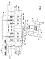
- the drive and drive systems shown in FIGS. 1 and 2 each have a rudder propeller 10, which is made an azimuth module 11 and a gondola arranged on this Propulsion module 12 composed.
- the azimuth module 11 is connected to a body 11a via a fixed part 11a Ship connectable.
- an azimuth drive 13 is disposed through an in-boat azimuth control 70 is controlled and which drives a rotatable part 11b of the azimuth module 11.
- an energy transmission device 14 is arranged, the one located in Propulsionsmodul 12 drive motor connects to the electrical system of the ship.
- the rotatable part 11b of the azimuth module 11 has auxiliary operations, such as for electrical supply or control, up.
- the in the Propulsionsmodul 12 arranged drive motor is as a permanent magnet Synchronous machine trained and drives two Propeller 16 on.
- the stator winding of the synchronous machine has three interconnected to a 3-phase alternating current Strands on, via the energy transfer device 14 with a arranged in the ship direct converter 20, the the electrical energy of the 3-phase alternating current in one Alternating current of certain voltage, frequency and number of phases, connected.
- the direct converter 20 serves to the Speed of the drive motor, and is on its Input side via three 3-winding transformers with the Wiring connected.
- the drive system shown in Fig. 1 has a Populsionsredundanzgrad RP of 50% on. Due to this homogeneous redundancy is achieved that the drive system even when occurring an error event in one of the rudder propellers 10 is available and therefore the ship is always manoeuvrable is, especially in bad weather conditions comes to fruition.
- Fig. 2 drive and drive system is with equipped with a partial redundancy and therefore also fulfilled the safety requirements of classification societies, such as Germanischer Lloyd.
- classification societies such as Germanischer Lloyd.
- This one demands that if a driving system is equipped with only one drive motor and the ship has no further propulsion system, To build this plant is that after a fault in the power converter or in regulation and control at least a limited driving is maintained.
- the aforementioned requirement is in the drive and driving system 2, characterized in that the rudder propeller 10 with a designed as a permanent magnet synchronous machine Drive motor is provided, the stator winding has six strands, of which three each to a 3-phase alternating current interconnected and via the power transmission device 14 with a power converter arranged in the ship 20a, 20b are connected.
- the power converters 20a, 20b Each is a mains-powered 6-pulse direct converter formed and each via a 4-winding transformer trained converter transformer 30a, 30b its input side with a medium voltage switchgear 40th connected to the electrical system of the ship.
- the direct converters 20a, 20b each consist of a group of three counterparallel switched line semiconductors 21a, 21b, 22a, 22b, 23a, 23b together, for each of which a recooling system 24a, 24b is provided.
- the subsystems formed in this way are each one own regulation and control device 25a, 25b, 26a, 26b assigned, each with a low-voltage switchgear 50th the electrical system of the ship in connection, as Fig. 2 lets recognize.
- Each subsystem is further a programmable logic Safety device associated with 27a, 27b, with which generate both alarm and control signals to let.
- a monitoring device 60 serves to monitor energy production and distribution in the electrical system.
- the two subsystems are operated in parallel during normal operation.
- the control and regulating device 25a, 26a of the one Subsystem is used as a master while the device 25b, 26b of the other subsystem acts as a slave.
- a change from master to slave is only switched off Drive system possible.
- the rule and Control devices 25a, 25b, 26a, 26b of both subsystems independently from each other their respective actual values, such as Capture voltage and current is only the master serving control and regulation means 25a, 26a due their parent position for functions, such as Power plant protection, speed control, transvector control or pulse formation of the power semiconductors, both subsystems responsible. Serving as a slave control and regulating device 25b, 26b is blocked for this.
- the machine control room in which usually the medium and low voltage units and the MKR control panel and automation units are to be found, or a synchronous generator and a diesel engine or a gas turbine as a drive unit having energy generator unit.
- the serving as a prefabricated system module container is as Welded construction formed and in its dimensions for standardized transport with container ships.
- Of the Container is preferred as a so-called 20-foot container with a length of 6,055 m, a width of 2,435 m and a height of 2,591 m or as a 40-foot container with a Length of 12.190 m, a width of 2.435 m and a height standardized by 2.591 m.
- the prefabricated containers are used for this purpose usually inserted in the ship's system. This ensures a relatively easy disassembly, for example for service and maintenance purposes. Regarding the latter also have closable containers Doors making them accessible to qualified personnel.
- a container is usually with lighting and Outlets equipped and has a connection to the ship-side supply and exhaust air system or alternatively to the Air conditioning of a ship.
- a heat exchanger provided to the fresh water system the ship is connected.
- a drive and driving system provided by virtue of its redundant design a comparatively high security and reliability in terms of maneuverability guaranteed.
- the relatively high availability of the drive and driving system is mainly due to that erroneous operating states detected safely and quickly and necessary actions, such as alarm notification, power reduction or network disconnection, promptly become.
- marine propulsion systems arranged with an outboard Rudderpropeller, as provided by the SSP technology not just a natural aging and operational Wear, but also external influences, such as inclinations, vibrations, vibrations or deformations of the hull, are exposed, which can lead to disturbances are redundant drive systems for ships under safety-related aspects indispensable.
- control and Control devices 25a, 25b, 26a, 26b in a modular design from standard components, such as those under the name SIMADYN D and SIMATIC S7 are known is.
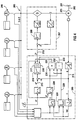
- the block circuit 101 of FIG. 3 shows the electromotive Drive 102 of the shaft 103 of a ship propeller 104 according to the engine telegraph 105 from the ship's captain predetermined speed setpoint 106 serving part of Control device of the drive and drive system.
- abrupt changes 105 of the speed setpoint 106 are implemented by a downstream ramp generator 107 in ramps with defined rise and fall speeds.
- This modified signal 108 for the speed setpoint n * passes via a summation point 109 to the input 110 of a speed controller 111, which is preferably realized with a proportional and an integral component.
- the inverted measuring signal 212 for the rotational speed n of the electric motor 102 which is determined by means of an incremental encoder 114 coupled to the shaft 113 of the electric motor 102 in the region of the B bearing plate, arrives at the input 110 of the rotational speed controller 111.
- a rotational speed proportional digital signal can be generated, which is then converted into an analog voltage 112 with the speed setpoint 108 corresponding amplitude. If the controller 111 succeeds in tracking the actual speed value n exactly to the modified speed setpoint value 108, the input signal 110 of the controller 111 becomes zero as a result of the difference formation n * -n at the summation point 109.
- the speed controller 111 changes its finite output signal 116, the amplitude of which can be understood as an acceleration or braking torque requested by the control stage. Since in the electric motor 102, which is preferably constructed as a three-phase asynchronous machine or three-phase synchronous machine, the torque generated in a suitable spin-oriented control, which will not be discussed here in detail, can be made approximately proportional to a current flow vector is so the controller output signal 116 of the speed controller 111 in the context of the circuit 101 at the same time construed as setpoint I * for a corresponding motor current and as such via a further summation point 117 to the input 118 of a secondary flow controller 119 led.
- This current regulator 119 basically also has a PI characteristic with a proportional and an integral component.
- the summation point 117 is inverted Measurement signal 120 for the motor current I, wherein the signal 120 for the actual current value I from one example.
- the power supply lines 121 of the electric motor 102 switched Shunts 122 obtained Stromistwert 123 by evaluation in a downstream transmitter 124 as an amplitude value is produced.
- This current amplitude value 120 may be at Three-phase asynchronous machines or three-phase synchronous machines 102 of the torque-forming component of the motor currents 122 detected current vector correspond, at a DC motor, however, the measured armature current can directly be used.
- the output signal 125 of the current regulator 119 reaches a Headset 126, which acts on a power converter 127.
- a Power converter 127 is on the primary side to a three-phase network 128 connected and in the case of a three-phase asynchronous machine or three-phase synchronous machine 102 as a converter, when using a DC motor 102 constructed as a power converter.
- the speed control circuit 129 subordinate current control circuit 130 ensures optimum adjustability of the engine torque 102, which in the context of the parent speed control 129 can be used to get the actual speed value 112 track the speed setpoint 108 exactly. This must the engine 102, however, a time-varying torque leave because the propeller 104 in a slip past his Leaves 131 on the existing on the hull skeg or Wellenbock experiences an increased braking torque and thus the about constant mean value of the load torque a harmonic superimposed whose frequency is about the product of the propeller speed corresponds to the number of propeller blades.
- the motor must 102 constantly apply a correspondingly varying drive torque, its reaction torque on the anchor 132nd the engine is introduced into the hull and there Causes vibrations with a corresponding frequency, which have a detrimental effect on the structure of the ship; in the opposite way the fluctuations affect the drive torque on the ship propeller and its Nachstromfeld such disadvantageous that the ship's propeller Cavitations are favored or triggered.
- the inventive countermeasure is that a part of the controller output signal 116 of the speed controller 111 is fed back 133.
- the controller 111 attempts to correct only to the correspondingly reduced speed setpoint n * -n R and thereby gives the motor 102 the opportunity to release flywheel energy from the drive train 102, 103, 104 by reducing the speed n from n * to n * -n R.
- the controller 111 of the decreasing engine speed n virtually a falling speed setpoint n * -n R is opposite and thus hardly countersteer. Therefore, the engine 102 generates no or little additional torque so that increased torque is not introduced to the engine hull 132 into the hull.
- the mean value of the speed n is slightly lower than the actual, constant speed setpoint n * , which can be seen as a permanent control deviation of about 0.2% to 1.5%.
- a compensation circuit may be inserted which n the speed setpoint * virtually by a corresponding amount adjusted upward.
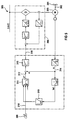
- An illustrated in Figure 4 in principle drive and drive system of a ship propeller 201 has an electric Propeller engine 203 coming from a diesel generator plant 206 via a vehicle electrical system 205 and a rectifier or converter 207 with electrical energy is supplied.
- the diesel generator system 206 may have a different number of diesel generators. This usually comes Synchronous generators used.
- the ship propeller 201 is driven by a drive shaft 202 driven by the electric propeller motor 203.
- the electric propeller motor 203 is a speed control 209 and the inverter or power converter 207 with current control assigned, by means of which the speed of the output shaft 202 the electric propeller motor 203 and thus the speed of the ship propeller 201 is adjustable.
- a current regulator 208 of the conversion or power converter 207 On the input side receives a current regulator 208 of the conversion or power converter 207 a current setpoint I * 219 of a rotation speed controller 216. n The a predetermined speed * 213 corresponding current setpoint I * 219 is except for the current controller 208 from the speed controller 216 or to the input side of an adaptive ramp transmitter 226 created.
- the adaptive ramp generator 226 On the output side, the adaptive ramp generator 226 has a positive offset stage 230 and a negative offset stage 232.
- the current setpoint I * 219 is provided with a variation range, wherein an upper 231 and a lower limit 233 of this variation range are passed from the output side of the adaptive ramp generator 226 to the output side of the speed controller 216, at which an upper current value limiting unit 217 and a lower current value limiting unit 218 are provided.
- the speed controller 216 From the upper current value limiting unit 217 and the lower current value limiting unit 218, the speed controller 216 has a variable setting range within which the output-side current setpoint I * 219, which is passed on to the current controller 208, has to remain.
- predetermined limit values are taken into account by the diesel generator system 206 and the vehicle electrical system 205.
- the one variation range within which the output side of the speed controller 216 can change this leaving current setpoint I * 219 is limited. It must be taken into account here that it must be ensured that the electrical system 205 can dynamically follow the electric propeller motor 203.
- the dynamic limits for load changes in the electrical system 205 or the electric propeller motor 203 are highly dependent on the characteristics of the diesel generator system 206, wherein in principle the diesel engines and the generators of the diesel generator system 206, which are usually designed as synchronous generators, are to be considered separately.
- the adaptive ramp generator 2226 In the adaptive ramp generator 226, a high and a return time for the current setpoint I * 219, which is forwarded by the speed controller 216 to the current controller 208, given, in the design of this ramp-up and ramp-down time permissible load and discharge of the diesel engines Diesel generator plant 206 is taken into account. To take this into account, the ramp-up and ramp-down time determined in the adaptive ramp generator 226 changes proportionally with the amount of the rotational speed n 215 of the electric propeller motor 203. This ensures that the active power received by a rectifier or converter of the drive device is one of the speed n 215 of the electric propeller motor 203 has independent rise and fall time.
- a minimum ramp-up and ramp-down time is considered, which after the permissible time change of the reactive power output from the Synchronous generators of the diesel generator plant 206 directed.
- the ramp-up and ramp-down times for the current setpoint I * 219 registered in the adaptive ramp function generator 226 are changed in inverse proportion to the number of diesel generators of the diesel generator system 206.
- the active power consumed by a diesel generator of the diesel generator system 206 has an up and down time which is independent of the operation of the rectifier or converter 207.
- the speed controller 216 In the regulated state, the speed controller 216 must be in a position to be able to carry the current setpoint I * 219 to be passed on to the current controller 208 free of limitations. Otherwise occur in the electric propeller motor 203 significant beats that affect the ship as mechanical vibrations or structure-borne sound sources and promote cavitation of the ship's propeller 201 or can trigger. For this reason, the current setpoint I * 219 from the output side of the speed controller 216, as usual, continues to go directly into the current controller 208 of Um- or
- the same current setpoint also goes in parallel to the adaptive ramp-function generator 226.
- the output side of this adaptive ramp-function generator 226 thus forms the above-described permissible dynamics of the diesel generators of the diesel generator system 206.
- the output value of the adaptive ramp generator 226 goes via the positive offset stage 230 or the negative offset stage 232 to the upper current value limiting unit 217 and the lower current value limiting unit 218 of the speed controller 216
- the speed controller 216 it becomes possible for the speed controller 216 to carry the current command value I * 219 to be forwarded to the current regulator 208 of the rectifier or converter 207 of the electric propeller motor 203 within a variation range which changes with respect to its position and width, whereby this variation range virtually results results in the moving window for the current setpoint I * 219 passed from the speed controller 216 to the current controller 208.
- the speed controller 216 is free to guide the current setpoint I * 219.
- the positive and negative offset 229 is a function of the amount of speed n 215 of the electric propeller motor 203, since the on-board power factor v on the modulation of the electrical propeller motor 203 associated Um- or power converter 207 depends. Furthermore, the positive and the negative offset 229 is proportional to the number of synchronous generators of the diesel generator system 206 feeding into the electrical system 205, since the short-circuit power Sk "in the vehicle electrical system 205 is likewise approximately proportional to the number of synchronous generators of the diesel generator system 206 feeding into the vehicle electrical system 205.
- the electric propeller motor 303 is in the usual way via a converter or converter 306 from a vehicle electrical system 305 supplied with electrical energy.
- the operation of the electric propeller motor 303 is controlled by means of a speed controller 315.
- the speed controller 315 By the output signal of the speed controller 315, the torque setpoint or current setpoint I * 316, the speed of the output shaft 302 of the electric propeller motor 303 via the inverter 306 is set.
- the speed controller 315 associated with an adaptive ramp generator 311.
- the adaptive Ramp generator 311 is by means of an input unit 309th a speed command value for the electric propeller motor 303 or the ship propeller 301 entered.
- a characteristic generator 319 is provided which, depending on the magnitude of an actual speed n 314 of the output shaft 302 of the electric propeller motor 303, transmits the signal n * 312 transmitted to the speed controller 315 from the output side of the adaptive ramp-function generator 311 for adaptation of the actual speed n 314 of FIG Output shaft 302 to the set on the input unit 309 predetermined speed 310 modified according stored in him curves.
- the amount of the actual rotational speed n 314 of the output shaft 302 of the electric propeller motor 303 serves as a reference variable for the signal n * 312 forwarded by the adaptive ramp generator 311 to the rotational speed controller 315.
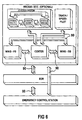
- Fig. 6 shows in a block diagram the various control options on the part of the control device. All about one and Output elements of the control station and the emergency control station predetermined change of the control gear takes place without setpoint jumps. By tracking the control levers on the part of the control station (bridge) and by corresponding key control on the other Control stations, a manual Fahrhebel Eisenstand is not required. With active control station (main control station: bridge) the setpoint specification of speed and thrust direction takes place the propeller drives from this, as in Fig. 6 in the shown in the upper box. With active steering position on the side of the engine control room (ECR) only the speed specification of this, as in Fig. 6 in the second box shown from above. The thrust direction specification is done by the control station on the bridge.
- ECR engine control room
- Helm changes, especially joystick, track / speed pilot and Tandem operation is not possible.
- active emergency control as a control station (Emergency Control Station ECS) takes place the setpoint specification for thrust and thrust direction together by buttons on the emergency control station.
- Joystick, Track / Speed Pilot and tandem operation are not possible.
- the individual control stations and their modules are by means of a ring bus 90 for Communication connected as shown in Fig. 6.
- Fig. 7 shows the structure of an input and output element of Control device of a drive and driving system according to the invention, which serves as the main navigation station on the bridge of a Ship is used.
- the input and output element consists it consists of several text display ads with a resolution four lines of 20 characters each.
- the Input and output element several buttons, the following be explained in more detail.
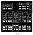
- Fig. 10a, 10b shows a as Module formed sub-range of the input and output module in Details.
- buttons “OPERATION BLOCK” With the button “OPERATION BLOCK” is the operation of the driving system prevented and the inverter of the electrical system set to controller inhibit. All function keys, which switch the respective drive, locked. Further the setpoint input is blocked by the control levers, as well the selection of the emergency operation buttons for the setpoint specification of Speed and thrust direction. The keys “OPERATION BLOCK” are protected against unintentional operation by flaps. The activated function is signaled by a continuous light. A lifting of the blockage is only possible if the Fahrhebel too stands on stop and at least two generators are on the net.
- the bridge On the input and output element on the part of the control station the bridge becomes the actual values of shaft speed and SSP position indicated for both drives.
- the ads are included a format of 96 x 96 mm.
- All displays of the input and output element of the control station on the bridge are dimmable via dimming potentiometers.
- the ads the membrane keyboard of the input and output element are realized via the integrated dimming function.
- the "Emergency Speed Control” button 410 is used to activate the Speed specification of the respective drive on the emergency control buttons placed.
- the Lamp When the emergency control is active, the Lamp in a steady light.
- the lamps light up when the button is pressed and selected Emergency control.
- the buttons are directly connected to the speed controller connected by appropriate lines (wired).
- the alarm text display 412 displays the most important fault messages displayed in plain text. For the operation of the alarm system four keys are provided, the present below the alarm text display 412 are arranged.
- the analog value display 413 can display eight analog values from the drive system represent. The analog values are over the keys described below are selected. The selected one Function is indicated by an LED. Each selected Display will automatically turn off after about 30 seconds deselected. After deselection becomes the available Power displayed (Remaining Power (kw)).
- the “Thrust Direction” button 414 is used to select the thrust direction indicator.
- the “Remaining Power” button 415 is used for Display of the available power.
- the key “Shaft Power” 416 is used to select the shaft power indicator.
- the “Shaft Speed” button 417 is used to select the shaft speed display.
- the “Stator Current” button 418 is for selection the stator current indicator.
- the button “Stator Voltage” 419 Used to select the stator voltage indicator.
- the key “Torque” 420 is used to select the torque value display.
- the module of the input and output element of the control station marked "Propulsion Mode” by the bridge, has 421 keys and displays in this area, which are used to select the operating modes.
- the keys have the following functions: In "Single Mode" (button 422), both SSP driving systems are operated separately. The driving commands for thrust direction and speed are specified by the control lever of the active control station for the respective drive. The port control joystick controls the SSP on-port side and starboard controls the SSP on the starboard side. The key 422 is released only when the control station is selected by the bridge.
- Joystick operation is selected via the "Joy Stick” button 424.
- the setpoint is set for Control angle and speed of the joystick system.
- the control levers, which have an electrical wave are over the same tracked.
- the "Joy Stick” button 424 is only on selected control station enabled by the bridge.
- Habour Mode 427 is the so-called port mode selected. In harbor mode, the SSP rotation angle is unlimited. The thrust adjustment is set to the maximum Speed provided. This is done by starting a second SSP hydraulic pump. In harbor fashion is blocked the automatic discontinuation of the generators.
- the key 427 is only with the control station selected by the bridge released by the ship.
- the "Sea Mode" button 428 is used to select Sea Mode. in the Sea mode, the control angle of the SSP is limited to about x / -35%. The thrust direction adjustment works with a hydraulic pump. Button 428 is only with the control station selected released from the bridge of the ship.
- the "Crash Stop” button 429 starts or stops the sequence Crash stop.
- the button lights up when the crash-stop function is activated with a steady light.
- the crash-stop feature will started or stopped together for all active drives (SSP).
- SSP active drives
- the button is by a protective cover against unintentional Acting protected and only with active control station released from the bridge.
- the display "Steering Control Failure” 431 shows a failure control system for SSP adjustment. It is no rudder adjustment available.
- the display "Steering Mechanic Blocked” 432 shows with a red steady light indicates that the azimuth adjustment of the SSP is mechanical is blocked. A tax with this facility is in not possible in this state. The propulsion of this plant is possible with limited moment.
- the ads 433 “Phase / Overload Pump” show phase errors or overloads of the Hydraulic pump 1 or 2 on.
- the ads 434 "Supply Power Unit 1/2 "show interference or loss of power supply for the hydraulic pump 1 or 2 for Azimuthvergna at.
- the display 435 "Electric Shaft Failure" appears with a red steady light when the electric shaft of the control lever failed for the thrust default or an error reports.
- the display 436 "Hydraulic Locking Failure" shows a loss of function the hydraulics for azimuth adjustment.
- the SSP does not follow the specified angle of rotation setpoint.
- the display 437 "Hydraulic Oil Tank Level” shows with a red steady light the loss of hydraulic oil in the hydraulic system the SSP azimuth adjustment. The hydraulic oil level has then reached the minimum level.
- the display 438 "Stand-by Pump” shows a fault in the hydraulic system which led to a pressure loss. It will the inactive hydraulic pump starts automatically. The faulty pump is switched off. This is displayed Function by a red steady light. The automatic switching is only active in the "Sea Mode", which uses the Key 428 can be activated.
- the key 439 "Hydraulic pump 1/2" serves for selection and operation display the pump 1 or 2 from the hydraulic system of SSP azimuth control.
- the key 439 is only with selected control station released from the bridge of the ship.
- the display 441 "Shut Down" appears in case of complete failure the drive by an automatic shutdown.
- the display 442 "Slow Down” alerts with a red steady light an automatic reduction of the drive. An automatic Reduction can be achieved by pressing the "Slow Down Override "446.
- the display 444 "Slow Down Request" alerts with a red Flashing light the request for a reduction of the drive to protect the machine.
- Button 445 "Shut Down Override" is used to cancel one automatic shutdown.
- An automatic shutdown the by a server can be canceled indicated by a flashing red display "Shut Down”.
- the Cancellation of the shutdown is time delayed.
- the key 445 is protected by a protective cover against unintentional operation protected and only with selected control station by the Bridge of the ship released.
- Button 446 "Slow Down Override" is used to cancel one automatic reduction. An automatic reduction that can be picked up by an operator is by a flashing red indicator of the "Slow Down Override” lamp is displayed. The button 446 is only on the selected control station side the bridge of the ship released. The button is through a protective cover protected against unintentional operation.
- the display 448 "Remote Control Failure" appears when a Controlling the system with the drive lever is not possible. It must be switched to the emergency control buttons, as already explained above.
- the display 449 "90% Power" appears with a red steady light, if it is recognized by the power plant protection that 90% of the available power are reached.
- the display 450 "Power Limit Active" appears with a red one Steady light, if a limitation of the drive is active.
- the display 451 "Lever to 0" appears with a red steady light, if the system state a zero compulsion of the Driving lever required.
- the display 452 "Electric Shaft Failure" appears with a red steady light when the electric shaft of the speed command has failed or reports an error.
- the display 453 "Start Fail" appears with a red steady light, if the boot sequence is interrupted by an error becomes. After activating the stop or start sequence, the Advertisement taken back.
- the display 454 "Propulsion Failure" appears with a red Steady light when the drive control fails within recognizes the drive.
- the indicator "Converter Tripped" 455 lights up with a red one Steady light when the inverter 1 or 2 of the SSP has failed is.
- the display "Propulsion Ready” 456 appears with a green Continuous light when drive and control are ready for operation. When the start sequence has been run through and the driving system is not ready, this indicator flashes. The lamp goes out after passing through the stop sequence.
- the display "Start Blocked" 457 appears with a red one Steady light when the system is not ready to start. This means, that there is no startup enable for the boot sequence is.
- the display 458 "Converter in Operation” appears with a green steady light when the inverter unit 1 or 2 on the network and is ready.
- the "Start Propulsion" button 459 is used for automatic preparation the drive system. This includes the switching of the recooling system on driving, switching on the inverter, request the hydraulic pumps for azimuth adjustment and release the shaft brake. During the start sequence, the display flashes with green light. At rest, the sequence is the lamp out. The key 459 is only on the selected control station side the bridge of the ship released.
- the "Stop Propulsion" button 460 is used for automatic settling the drive system. This includes the switching of the recooling system on stand-by, switching off the inverter, stopping the hydraulic pumps for Azimuthvergna and insert at the end the shaft brake. During the stop sequence, the display flashes with red light. In the idle state of the sequence lights the lamp with a red steady light. The button is only on selected control station enabled by the bridge.
- the "Converter Selected” button 461 is used to select inverters 1 or 2. By pressing a button, the inverter 1 or 2 selected or deselected. There must be at least one inverter 1 or 2 selected. For selection, the system must be in the state off be. The button is only on the selected control station by the Bridge of the ship released.
- Control Station 462 are the buttons and indicators arranged to dial and Display of the active control station or control station.
- the button "Bridge Control” 463 is used to select the control station from the bridge.
- the lamp of button 463 shows the Initiation of the change of the driving gear to the bridge and the active ones Control station of the bridge.
- the "ECR Control” button 464 is used to select the control station ECR (Engine Control Room).
- the lamp of the key 464 shows the Initiation of the change of driving gear to the ECR and the active ones Control station ECR active.
- Key 466 changes the steering position of the steering wheel selected. With initiation of the transfer the key 466 flashes. The transfer takes place with the key "Take Control” 467 at the helm of the steering wheel. The signaling done with a steady light. The button is only on selected control station released by the bridge of the ship.
- the "Take Control” key 467 is for confirmation and for Takeover of the control station provided. She will be part of a Steering position switching used. Flashes when requested the "Take Control" lamp of button 467. Lights up the display with steady light, exactly this control station is activated. The Display is used to distinguish the active auxiliary control statuses on the bridge.
- the levers 470 for SSP port and starboard serve for Specification of the speed and the thrust direction of the drive.
- the Control lever of the individual control stations that is, emergency control stations, Bridge and the like, are connected to each other via an electric shaft connected. This results in a tracking of the Not selected control stations for thrust as well as thrust direction.
- the electric waves of connected to both drives In tandem mode, the electric waves of connected to both drives.
- the setpoint specification for thrust and direction for both drives via a Lever.
- the control device of the drive and driving system such as Track / Speed Pilot or the Joy Stick become the driving levers according to the reference for speed and thrust direction tracked.
- the drive lever of the input and output element of Control station on the bridge have during the joystick or Track / Speed Pilot operation an override function. The operator has the option during the operation of joy stick or track / speed pilot via the throttle 470 in the Driving operation intervene.
- the "Emergency Telephone" button can be used to select the driving commands from the helm on the bridge of the ship to the ECR the emergency control station are transmitted, as shown in Fig. 6.
- the commands of the Key telegraph sequence to be done.
- the ECR or emergency control station sounds as long as an acoustic signal until the Command of the bridge is confirmed.
- the helm stations are included - As shown in Fig. 6 and already explained - via a Ring bus connection 90 connected for communication.
- an emergency stop button 471 For each drive an emergency stop button 471 is provided, the protected by a protective cover against unintentional operation is.
- the emergency stop is from the currently active control station independently.
- the depressed key 471 is indicated by a Flashing marked.
- a SSP for port and starboard provided in the upper part of the input and output element of a bridge side Control station of the control device according to FIG. 7 .
- the ads have a size of 144 x 144 mm and are dimmable via a common dimming device.
- the dimming device is in the input and output element of the control device integrated and presently with the reference numeral 472 marked.
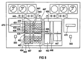
- Fig. 8 shows an embodiment of an input and output element an emergency control station. As can be seen from FIG. 8 is, has the input and output element of the emergency control station Although fewer input and output elements on how the Fig. 7 illustrated input and output element of the control station from a bridge of a ship to emergency control However, necessary functions are also in the input and output element an emergency control gear according to FIG. 8 realized.
- an emergency control station instead of the analog value display 413 provided in FIG has the input and output element of an emergency control station according to 8 shows the actual values of the shaft power for both Drives pointer instruments on, which according to the indications for the actual values of shaft speed from SSP position approximately have the format of 96 x 96 mm.
- the modules are the input and output elements the various control stations with the control device, the control device, the azimuth modules, the propulsion modules, the various modules of the control device and the motors of the drives and the like with each other connected to a ring bus system. This allows a very high easy communication between the different modules and beyond with simultaneous presentation on the part the input and output element a simultaneous value query in dialogue.
- Fig. 9 shows a further embodiment of an input and output element an emergency control station of the control device.
- This is a so-called "Emergency Control Station", which is arranged, for example, aft.
- the input and output element of the control device according to FIG. 9 is also a ring bus system with the various Modules of the drive and drive system for ships connected.
- the input and output element to Control of the drive motors, the azimuth modules, the propulsion modules and the like directly connected to them, so that, for example, a failure of the ring bus system not for The consequence is that part of the emergency control station according to FIG. 9 a Control of the drive and driving system is impossible.
- the direct wiring of the input and output element allows the emergency control station providing a redundant Communication connection with the different modules of the drive and drive system.
- the emergency control station of FIG. 9 includes the controls for on-site control of the port and starboard SSP.
- the displays and buttons have the following functions: About the above-explained "Emergency Telephone" the driving commands can be transferred from the control station by the bridge of the ship to the emergency control gear shown in FIG. On the emergency control, the commands of the key telegram 475 must be followed.
- the ads have the format of about 96 x 96 mm, as shown in Fig. 9 and already in Connection with FIGS. 7 and 8 described in more detail.
- buttons are below the display released for the shaft speed for speed control. By pressing the buttons to increase or decrease the Speed lights up the corresponding button. The lamps are lit. only if the commands at the emergency control station (Emergency Control Station (ECS)) are released. The throttle on the bridge will be tracked accordingly.
- ECS Emergency Control Station
- the corresponding keys By pressing the ports for starboard or starboard rotation below the display of the actual values for the thrust direction the corresponding keys light up.
- the lamps only light up, when the commands are released at the emergency control station (ECS).
- ECS emergency control station
- the buttons are only used as a control station when emergency control is selected active.
- the control levers of the control station on the part of the bridge be tracked accordingly.
- Control Station 476 of the Input and output element of the emergency control gear are the buttons and indicators arranged to dial and Display of the active control station serve as control station.
- the display "Bridge Control" 477 shows the active control station from the bridge of the ship.
- the display "ECR-Control” 478 shows the active control station of the Engine room (ECR Engine Control Room).
- the display 479 shows the active control station of the emergency control station (ECS Emergency Control Station). If this ad 479 is lit with a steady light, the emergency control is the active control station. An operation of the control station 1 of the bridge of the ship is not possible.
- the display "POD Control" 480 indicates that in the POD the control station POD has been selected and is active. A remote control can not.
- the selector switch "Selector REM / ECS" 481 changes the control station of the emergency control station "ECS" selected or deselected.
- buttons and displays arranged for operation and Alerting for azimuth detection are provided.
- the keys 483 "Hydraulic pump” are used for selection and operation display the pump from the hydraulic system of the SSP azimuth control.
- the button is only available when the emergency control is selected added.
- the display 484 "Hydraulic Failure" shows an error of the Hydraulic system for SSP-Azimuth detection. An ad here can mean the loss of the rudder effect.
- the Collective Failure 485 indicator is a collective alarm signal. It shines when at least one error on the part of Control device of the drive and drive system for ships or a fault of the auxiliary equipment within the housing of the SSP has occurred.
- the shaft brake of the Drive engaged and released.
- the shaft brake can only be inserted if both inverters of the drives are not in Operation are.
- the lamp in the key 486 gives the feedback, whether the shaft brake is engaged.
- the key "POD cover” 487 becomes the locking bolt for the "POD access door reactivated, the key is only operable with selected emergency control (ECS) and with engaged Brake.
- ECS emergency control
- the lamp of the button 487 shows the unlocking at.
- the PUD is in the basic position posed.
- the lamp of button 488 lights up.
- the button 489 "Fan On” switches the fan for the POD. there the button 489 lamp indicates the status of the fan.
- the "Heater On” button switches the heating for the capital letter PUD.
- the lamp of the 490 button shows the status at.
- the display 491 "Disconnecting Valve” indicates that the shut-off valve between the first hydraulic pump and the second Hydraulic pump and the hydraulic tank is closed.
- the "Converter Selected” button 493 is used to select the inverter 1 or 2. By pressing the key, the inverter 1 or 2 selected or deselected. At least one inverter must be installed 1 or 2 selected. To dial, the system must be in Condition be off.
- the "Converter Run” screen 494 appears with a green light Steady light when the inverter unit 1 or 2 on the network and is ready for use.
- Each SSP has two power and speed control systems (power and speed control, PSU).
- the task of these systems is power plant protection and speed control of the drive. There is always one system active. If an error occurs, the operator can switch over to the other system.
- the "PSU 1/2 SEL" button 496 is used to select the active power and speed control system 1 ⁇ 2. When dialing one system automatically deselects the other system. The button 496 is the same as the emergency control station (ECS) released. To select a new system, the Drive be switched off.
- ECS emergency control station
- the "Start Propulsion" button 497 is used for automatic preparation the drive system. This includes the switching of the recooling system on driving and switching on the inverter. During the startup sequence, the display of button 497 flashes with green light. In the idle state of the start sequence is the lamp out. The button 497 is only available when the emergency control is selected given. From the emergency control only the inverter through the The “Start Propulsion" button 497 is ready for operation. The systems for azimuth detection and the shaft brake need be operated by the key in the area "Azimuthcontrol" 482. The key 497 "Start Propulsion" can only be operated if the shaft brake is not activated.
- the "Stop Propulsion" button 498 is used for automatic settling the drive system. This includes the switching of the recooling system on standby and turning off the inverters. During the stop sequence, the display of button 498 flashes with red light. When idle, the lamp lights up with a red steady light. The key 498 is only on Emergency control released. The settling of the hydraulic pumps for azimuth detection and the insertion of the shaft brake done by additional operation in the area "Azimuth Control" 482.
- the display "Propulsion Ready” 499 appears with a green Steady light when the drive and the controller are ready for operation are. When the start sequence has been run through and the driving system is not ready, the display 499 flashes. The Lamp of display 499 goes out after passing through the stop sequence.
- the display "Propulsion Failure" 500 appears with a red one Steady light when the drive control fails within recognizes the drive.
- buttons and displays are arranged which serve to select and display the emergency control station.
- ECS emergency control station
- an emergency stop button 502 "Emergency Stop" provided.
- the emergency stop is regardless of the active control station.
- the startup sequence is disabled when the lamp "Start Block" 457 is lit with a steady light.
- the "Start Propulsion” lamp flashes the key 459 with a slow frequency. After correct The lamp of button 459 goes out and the lamp goes through “Propulsion Ready” lights up green. The drive and drive system is ready for use. If the start sequence by a Error aborted, the lamp “Start Fail” 453 lights.
- the "STOP Propulsion" lamp flashes 460 with a slow frequency. After going through the first Step by step, the lamp “Propulsion Ready” on steady light. The system is now no longer operational and all systems are off. If the stop sequence by a Error canceled, the lamp "STOP Propulsion" goes off.
- the lamp lights up with a steady light.
- the crash stop is activated by pressing the crash stop button again on one of the input and output elements of the control device completed. After completing the crash-stop function the SSP remains in the current position and the speed setpoint remains is set to zero. After the crash stop has been completed is the driving again on “Harbor and Sea Mode. "The active throttle has the command again, after being reset to zero.
- a hydraulic pump per drive and the steering angle SSP is preferably limited to a maximum of +/- 35 °.
- the drive is without a 360 ° limit rotatable and there are two hydraulic pumps in operation. additionally the "Harbor Mode” is reported to the "Power Management". The power management leaves all active generators in "harbor mode", regardless of the unused power, on Network.
- the helm changes, as already in connection explained with Fig. 6, without setpoint jumps.
- the bridge is the setpoint specification of speed and Direction of thrust on the part of the helm of the bridge.
- active Control station on the part of the engine room (ECR) takes place only the Speed specification from the ECR control station.
- the thrust direction specification takes place on the part of the helm of the bridge.
- active Emergency control station the setpoint value is specified for thrust and thrust direction together by buttons on the emergency control, as above explained.
- the command specification by the control station of Bridge is done via phone regarding thrust direction and Thrust or by the built-in emergency graph with regard to of the thrust.
- Switching from the control room of the engine room on the helm from the bridge of the ship will be in Control station of the engine room by an acoustic alarm and signaled by flashing the "Bridge Control” lamp.
- the steering position loss is achieved by pressing the button “Bridge Control” in the control room on the part of the engine room acknowledged.
- the change to the ECS control station takes place by pressing the Selector switch "REM / ECS" from REM to ECS at the emergency control station. With the switch receives the emergency control directly tax.
- the "ECS Control” lamp on the emergency control goes over into a steady light.
- the steering position loss in the machine control station (ECR control station) is characterized by optical and acoustic Signaling on the ECR control gear input and output element (ECR panel) alarmed.
- the "ECR Control” lamp on the ECR panel goes out.
- the "ECS Control” lamp flashes on the ECR panel, until the steering position loss is lost with the "ECS Control "was acknowledged on the ECR panel with the acknowledgment also the acoustic signaling is terminated.
- the "ECS Control” lamp on the ECR panel has a steady light. On the bridge-side control station, the lamp “ECS Control "with a steady light and the lamp” ECR Control "goes out.
- the steering position loss on the bridge is caused by optical and acoustic signaling on the input and output element alarmed by the control of the bridge.
- the lamp “Bridge Control” on the input and output element of the bridge control station goes out.
- the "ECS Control” lamp flashes on the Input and output element of the bridge stand as long as, until the steering position loss with the "ECS Control” button on the side the bridge stand was acknowledged. With the acknowledgment also the acoustic signaling is terminated.
- the lamp “ECS Control” on the bridge stand has a steady light.
- the "ECS Control” lamp appears in the ECR control station with A steady light and the lamp “Bridge Control” goes out.
- the change from emergency control to a so-called remote control station is done by pressing the selector switch "REM / ECS" from ECS to REM at the emergency control station.
- the Control stations of the bridge and the engine room (ECR) at the same time selected.
- the "Bridge Control” lamp flashes on the bridge and there is an audible alarm.
- the "ECR Control” lamp flashes and this also sounds Horn.
- the controller is taken over by the bridge control station by pressing the "Bridge Control” button on the on and off Output element of the bridge-side control station is the Lamp “Bridge Control" in a steady light and the horn silent.
- the bridge-side control station has now Command.
- the override function is at any time by the operator with a press the slowdown override key again.
- the override is reported to the alarm system.
- the override is reported to the alarm system.
- the inverter cooling system has three operating modes.
- the first mode is the shutdown state. This State is reached by the pump starters of "Automatic” be switched to “hand”. In manual mode, the Pump off by the operator if necessary.
- the second operating mode is stand-by mode.
- the stand-by operation is activated by switching the pump starters from manual to automatic mode.
- the stand-by operation of Recooling system is active when the drive system is switched off is ("PROP STOP" active).
- PROP STOP active when the drive system is switched off.
- the pumps the recooling system started at intervals to the conductance of cooling water to maintain a value of an immediate Start of the drive system allows.
- the third operating mode is operation when the drive system is activated. In this mode, one of the two cooling water pumps operated continuously. The other pump serves as a standby pump.
- Each SSP drive can be controlled individually by the emergency sequencer assigned to it being stopped.
- Each emergency stop is designed as a detent switch. actuated Switches are indicated by a flashing signal.
- SSP position indicators are the “Turn the SSP to port and starboard. "The direction of rotation is made clear by arrows.
- buttons just mentioned must be the emergency button control to be activated.
- the button To activate, the button must "Emergency Steer” be pressed.
- the activated emergency key control is indicated by a steady light.
- buttons of the emergency control are on the nocks and the Center control station connected in parallel.
- timing is active. Signals of the keys respectively. are routed directly to the valves of the control hydraulics.
- buttons just mentioned must be the emergency button control to be activated.
- the button To activate, the button must "Emergency Speed Control" be pressed.
- the activated Emergency button control is indicated by a steady light.
- All emergency control buttons are located on the nocks and the center console connected in parallel.
- timing is active. Signals of the keys respectively. are routed directly to the inputs of the speed control module.
Abstract
Description
Die Erfindung betrifft ein Antriebs- und Fahrsystem für
Schiffe gemäß Oberbegriff des Patentanspruchs 1 bzw. Oberbegriff
des Patentanspruchs 2; ein derartiges Antriebs- und
Fahrsystem ist z.B. durch die Druckschrift "Siemens-Schottel-Propulsor
(SSP). The podded electric drive with permanently
excited motor", SIEMENS-SCHOTTEL, März 1997 (1997-03),
XP000198528 bekannt.The invention relates to a drive and drive system for
Ships according to the preamble of
Bei einer derartigen, in der Praxis auch unter der Bezeichnung SSP bekannten Antriebstechnologie handelt es sich um einen drehbaren Schiffsantrieb, der vorzugsweise im Bereich des Hecks eines Schiffes angeordnet ist und zugleich die Funktionen Antrieb, Ruder und Querschuberzeugung erfüllt. Der SSP-Antrieb zeichnet sich ferner durch einen geringen Schiffswiderstand bei den verschiedensten Schiffsrümpfen aus und bedarf keiner zusätzlichen Kühlung, da diese durch das den Antriebsmotor im Propulsionsmodul umströmende Wasser bewirkt wird. Überdies ist der SSP-Antrieb mit geringen Benutz- und Wartungskosten verbunden und bietet den Vorteil einer besonders hohen Kraftstoffeffizienz.In such, in practice, even under the name SSP known drive technology is one rotatable marine propulsion, preferably in the area of Rear of a ship is arranged and at the same time the functions Drive, rudder and transverse thrust generation met. The SSP drive is also characterized by a low ship resistance in the most diverse hulls and needs no additional cooling, as this by the drive motor causes water flowing around in the propulsion module becomes. Moreover, the SSP drive with low user and Maintenance costs and offers the advantage of a special high fuel efficiency.
Im Bereich der Schiffsantriebstechnologie besteht im Hinblick auf die Wettbewerbsfähigkeit der einzelnen Unternehmen ein zunehmender Bedarf, die Entwicklungszeiten zu reduzieren und die Herstellkosten zu senken. Zugleich werden aber auch Antriebssysteme benötigt, die den zufälligen Ausfall einer Komponente beherrschen, so dass nach einem im Antriebssystem auftretenden Fehler die Manövrier- und Steuerfähigkeit eines Schiffes schnellstmöglich wieder gewährleistet ist.In the field of marine propulsion technology exists with regard to on the competitiveness of individual companies increasing need to reduce development times and to reduce the manufacturing costs. At the same time, but also drive systems requires the accidental failure of a component dominate, so after one in the drive system occurring error the maneuverability and controllability of a Ship as soon as possible.
Weiterhin ist es im Schiffbau üblich, dass elektrische und elektromechanische Bauteile, wie etwa Motoren, Transformatoren, Schalt-, Stromrichter- und Rückkühlanlagen oder Steuerstände, einzeln von den jeweiligen Herstellern an die Schiffswerft geliefert werden, um dann von dem Werftpersonal auf entsprechend vorbereitete Fundamente im Schiff befestigt und untereinander verkabelt sowie auf ihre Funktion hin überprüft zu werden. Nachteilig hierbei ist ein beträchtlicher logistischer und damit kostenintensiver Aufwand, der zudem dadurch erhöht wird, dass sowohl die Fertigung der einzelnen Bauteile als auch die Verkabelung und Überprüfung des kompletten Systems der Kontrolle einer Klassifikationsgesellschaft, beispielsweise American Bureau of Shipping (ABS), Bureau Veritas (BV), Der Norske Veritas (DNV), Germanischer Lloyd (GL) oder Lloyds Register of Shipping (LRS), bedarf.Furthermore, it is common in shipbuilding that electrical and electromechanical components, such as motors, transformers, Switching, converter and recooling systems or control stations, individually from the respective manufacturers to the Shipyard to be delivered by the shipyard staff attached to appropriately prepared foundations in the ship and wired together and checked for their function to become. The disadvantage here is a considerable logistical and thus costly effort, in addition This increases that both the manufacture of the individual Components as well as the wiring and verification of the complete System of control of a classification society, for example American Bureau of Shipping (ABS), Bureau Veritas (BV), The Norske Veritas (DNV), Germanischer Lloyd (GL) or Lloyd's Register of Shipping (LRS).
Der vorliegenden Erfindung liegt die Aufgabe zugrunde, ausgehend vom eingangs genannten Stand der Technik ein Antriebsund Fahrsystem für Schiffe zu schaffen, mit dem sich eine vergleichsweise hohe Sicherheit im Hinblick auf eine zuverlässige Manövrierbarkeit eines Schiffes auf verhältnismäßig kostengünstige Weise erzielen lässt.The present invention is based on the object starting from the above-mentioned prior art, a drive and To create a driving system for ships with which a comparatively high safety with regard to a reliable Maneuverability of a ship on relative achieve cost-effective manner.
Diese Aufgabe ist bei einem Antriebs- und Fahrsystem gemäß
Oberbegriff des Patentanspruchs 1 erfindungsgemäß dadurch gelöst,
dass eine aus standardisierten Baugruppen modular zusammengesetzte
Steuer- und Regeleinrichtung für jeden der Ruderpropeller
vorgesehen ist.This object is according to a drive and driving system
The preamble of
Durch ein solchermaßen ausgestaltetes Antriebs- und Fahrsystem wird den steigenden Anforderungen an die Zuverlässigkeit und Sicherheit eines Schiffes im hohen Maße Rechnung getragen. Dies ist in erster Linie auf das Vorhandensein wenigstens zweier gleicher Ruderpropeller mit autonomer Steuerund Regeleinrichtung zurückzuführen, durch die sich eine homogene Redundanz des Antriebssystems ergibt. Bei Auftreten eines Fehlerereignisses in einer mechanischen oder elektrischen Komponente eines Ruderpropellers steht damit zumindest ein Reserveantrieb zur Verfügung, der die Manövrierfähigkeit des Schiffes gewährleistet. By such a configured drive and driving system will meet the increasing demands on reliability and safety of a ship to a high degree. This is primarily due to the presence at least two identical Rudderpropeller with autonomous Steuerund Due to a homogeneous control Redundancy of the drive system results. Upon occurrence an error event in a mechanical or electrical Component of a rudder propeller is thus at least a reserve drive available, which maneuverability of the ship.
Ferner trägt der modulare Aufbau der Steuer- und Regeleinrichtung aus standardisierten Baugruppen zu einer verhältnismäßig kostengünstigen Herstellung bei.Furthermore, the modular structure of the control and regulating device contributes from standardized assemblies to a relative inexpensive production.
Zur Lösung der oben genannten Aufgabe wird bei einem Antriebs-
und Fahrsystem gemäß Oberbegriff des Patentanspruchs
2 vorgeschlagen, dass eine aus standardisierten Baugruppen
modular zusammengesetzte Steuer- und Regeleinrichtung für jedes
der beiden Teilsysteme vorgesehen ist.To achieve the abovementioned object, in a drive
and driving system according to the preamble of the
Auch ein solches Antriebs- und Fahrsystem trägt dem Zufallsausfall einer Komponente Rechnung und lässt sich aufgrund der vorgenannten Gründe in wirtschaftlicher Hinsicht günstig herstellen. Die sich infolge des einzig vorhandenen Ruderpropellers hierbei ergebende Teil-Redundanz des Antriebssystems wird durch die autonomen Teilsysteme erzielt, die dafür Sorge tragen, dass bei einer auftretenden Störung zumindest ein eingeschränkter Fahrbetrieb des Schiffes aufrecht erhalten bleibt.Even such a drive and driving system contributes to the random failure a component bill and can be due to the produce the above reasons economically from an economic point of view. The result of the only existing Rudderpropellers resulting partial redundancy of the drive system is achieved through the autonomous subsystems that provide for it wear that at a fault occurring at least one maintained limited driving of the ship remains.
Von besonderem Vorteil ist es, wenn beide Teilsysteme parallel betreibbar sind, wobei eine der Regel- und Steuereinrichtung der Teilsysteme als Master und die andere als Slave einsetzbar ist. Durch den parallelen Betrieb der beiden Teilsysteme ergibt sich zum einen eine aktive Redundanz des Antriebssystems, während zum anderen durch die Master-Slave-Anordnung der Regel- und Steuereinrichtungen eine übergeordnete Steuerung für beide Teilsysteme sichergestellt ist. Auf diese Weise ist es möglich, dass gewisse Aufgaben, wie etwa die Drehzahlregelung, ausschließlich von der als Master dienenden Regel- und Steuereinrichtung übernommen und für die als Slave eingesetzte gesperrt sind.It is particularly advantageous if both subsystems are parallel are operable, one of the control and regulating device the subsystems can be used as master and the other as slave is. Due to the parallel operation of the two subsystems results in an active redundancy of the drive system, while on the other by the master-slave arrangement the control and regulating a parent Control is ensured for both subsystems. On In this way it is possible that certain tasks, such as the speed control, exclusively by the master Control and taken over and for the are locked as slave used.
Von Vorteil ist ferner, wenn jedem Teilsystem eine speicherprogrammierbare Sicherheitseinrichtung zugeordnet ist, die neben Alarmsignalen automatische auch Regel- und Steuersignale erzeugt. Durch derartige Regel- und Steuersignale können beispielsweise die Motordrehzahl oder der Ständerstrom unverzüglich reduziert werden, wenn eine Störung in einem der Teilsysteme detektiert wird.It is also advantageous if each subsystem has a programmable logic Safety device is assigned, the In addition to alarm signals automatic control and control signals generated. By such control and control signals can For example, the engine speed or the stator current immediately be reduced if a fault in one of Subsystems is detected.
Gemäß einem weiteren Merkmal der Erfindung weist jeder Stromrichter eine Phasenstromregelung auf. Dies bietet den Vorteil, dass der Strom mit variabler Frequenz der Synchronmaschine aufgeprägt werden kann. Gemäß einem weiteren Merkmal der Erfindung ist der Phasenstromregelung eine als Transvektorregelung ausgebildete feldorientierte Regelung vorgeschaltet, um dem Antrieb eine hohe Dynamik zu verleihen. Die Aufgabe der Transvektorregelung besteht dabei darin, aus den Ist-Werten der Ständerspannung, Ständerströme und der Polradlage der Synchronmaschine die Lage des magnetischen Flusses zu bestimmen, wobei der Sollwert des drehmomentbildenden Ständerstroms senkrecht zur ermittelten Flussachse vorgegeben wird.According to a further feature of the invention, each power converter a phase current control on. This offers the advantage that the variable frequency current of the synchronous machine can be imprinted. According to another feature the invention is the phase current control as a transvector preceded by field-oriented regulation, to give the drive a high degree of dynamics. The task the transvector control consists of the Actual values of the stator voltage, stator currents and the pole wheel position the synchronous machine the position of the magnetic flux to determine, with the setpoint of the torque-forming Ständerstroms set perpendicular to the determined flow axis becomes.
In Weiterbildung der Erfindung wird ferner vorgeschlagen, dass eine Überwachungseinrichtung vorgesehen ist, durch welche die Energieerzeugung und -verteilung im Bordnetz gegen eine Überbelastung durch den Antriebsmotor schützbar ist. Dies stellt sicher, dass der Sollwert der Drehzahl beschränkt wird, wenn die von dem vorgegebenen Sollwert geforderte Leistung des Propellers die verfügbare elektrische Leistung im Bordnetz des Schiffes übersteigt. Überdies ist es möglich, bei Störungen im Bordnetz einen geänderten Sollwert vorzugeben, um eine Überlastung der Energieerzeugeraggregate und damit einen "black out" im Bordnetz zu vermeiden. In a further development of the invention is also proposed a monitoring device is provided by which the energy production and distribution in the electrical system against an overload can be protected by the drive motor. This ensures that the setpoint limits the speed when the power demanded by the given set point of the propeller the available electric power in Wiring of the ship exceeds. Moreover, it is possible to specify a changed setpoint in the event of faults in the vehicle electrical system to overload the power generator sets and thus to avoid a "black out" in the electrical system.
Gemäß einer weiteren bevorzugten Ausgestaltung der Erfindung sind die einzelnen Komponenten des Antriebs- und Fahrsystems in wenigstens einem vorgefertigten Container angeordnet. Unter einem Container wird dabei eine nahezu eigenständige Funktionseinheit verstanden, die mit Schnittstellen zu anderen Schiffssystemen, etwa der Steuerung, versehen ist. Dies bietet die Möglichkeit, das Antriebssystem unabhängig vom Bauort des Schiffes weitgehend zu verkabeln und auf seine Funktion hin zu überprüfen. Nach dem Versand zur Schiffswerft ist es dann lediglich noch erforderlich, den Container auf einem vorbereiteten Fundament des Schiffes zu befestigen und mit dessen Leistungs- und Steuerungssystem zu verbinden. Da eine Verkabelung der einzelnen Komponenten des Antriebssystems auf der Schiffswerft somit entbehrlich ist, entfällt auch die logistische Erfassung der einzelnen Bauteile auf der Werft, wodurch sich eine einfachere und übersichtlichere logistische Planung ergibt. Darüber hinaus lässt sich auf diese Weise eine flexible Anlieferung und damit ein zu einem optimalen Zeitpunkt stattfindender Einbau des Containers erreichen. Aufgrund eines einzigen Fundaments für den Container anstelle diverser Fundamente für die einzelnen Komponenten ist zudem ein geringerer und damit kostengünstigerer Fertigungsaufwand sichergestellt.According to a further preferred embodiment of the invention are the individual components of the drive and drive system arranged in at least one prefabricated container. Under a container becomes an almost independent one Functional unit understood with interfaces to others Ship systems, such as the controller, is provided. This offers the possibility of independent of the drive system Construction site of the ship largely to cable and on his Function to check out. After shipping to the shipyard then it is only necessary to open the container to fix a prepared foundation of the ship and to connect with its power and control system. There a wiring of the individual components of the drive system is dispensable on the shipyard, is eliminated also the logistic registration of the individual components on the Shipyard, resulting in a simpler and more clear logistical Planning results. In addition, it can be based on this A flexible delivery and thus an optimal Reach the time of installation of the container. Due to a single foundation for the container instead of various foundations for the individual components is also a lesser and therefore less expensive manufacturing effort ensured.
Um einen vorgefertigten Container mit herkömmlichen Containerschiffen zur Schiffswerft transportieren zu können, wird schließlich vorgeschlagen, dass die Abmessungen der Container standardisiert sind.To a prefabricated container with conventional container ships to be transported to the shipyard finally suggested that the dimensions of the container standardized.
Gemäß einem weiteren vorteilhaften Vorschlag der Erfindung ist an dem Container eine Einheit zur Positionsfernüberwachung angeordnet. Dabei kann es sich vorzugsweise um eine GPS-Einheit handeln. Dadurch wird ermöglicht, über GPS-Systeme den exakten Standort eines Containers zu ermitteln. Dadurch kann der Weg des Containers von der Verladung über den Transport bis zum Bestimmungsort überprüft werden. Es bieten sich dazu z.B. die Verwendung vorhandener GPS-Systeme an, z.B. den im Bereich der Seefahrt bereits genutzten IN-MAR-SAT-System. Durch die Ausgestaltung kann auf einfache Weise sichergestellt werden, dass die entsprechenden Container auf dem richtigen Weg zum richtigen Bestimmungsort gelangen. Durch diese Ausbildung der GPS-Einheiten als demontierbare Einheiten am Container, beispielsweise Einheiten bestehend aus Sender, Energieversorgung und dergleichen, kann nach Ankunft des Containers am richtigen Ort die Einheit zum Container entfernt und wieder verwendet werden.According to a further advantageous proposal of the invention is a unit for position remote monitoring on the container arranged. This may preferably be a Act GPS unit. This will enable using GPS systems determine the exact location of a container. Thereby the way of the container from the loading over the Transportation to be checked to destination. It offer for example. the use of existing GPS systems, e.g. the IN-MAR-SAT system already used in the maritime sector. Due to the design can easily ensure that the appropriate containers are up get the right way to the right destination. Through this training the GPS units as removable Units on the container, for example, consisting of units from transmitter, power supply and the like, may upon arrival the container at the right place the unit to the container removed and used again.
Schiffsantriebe, insbesondere Ruderpropellerantriebe, erzeugen im Betrieb Schwingungen, welche sich durch den gesamten Schiffsrumpf fortpflanzen und diesen in Vibrationen versetzen. Während diese Schwingungen bei Dieselantrieben primär von den hin- und hergehenden Kolben verursacht werden, könnte vermutet werden, dass bei Elektromotoren, wie sie vor allem bei U-Booten, aber auch zunehmend bei Überwasserschiffen zum Einsatz gelangen, derartige Schwingungen nicht mehr auftreten. Dem ist jedoch nicht so, da insbesondere auch ein Schiffspropeller eine schwankende Belastung für den Antrieb darstellt, und zwar deshalb, weil die Propellerblätter bei ihrer Rotationsbewegung sich teilweise an dem am Schiffsheck vorhandenen Skeg oder Wellenbock entlang bewegen, auf einem anderen Teil ihrer Rotationsbewegung sich dagegen von diesem weitgehend frei bewegen können. Dieses schwankende Belastungsmoment wird von dem Drehzahlregler bzw. dem diesen untergeordneten Stromregler nachgefahren, um die Drehzahl der Schiffsschraube so exakt als möglich bei dem vorgewählten Drehzahlsollwert konstant zu halten. Hierbei überträgt sich das mit einer der um die Blätterzahl des Propellers vervielfachten Wellendrehzahl schwankende Drehmoment auf den Antriebsmotor und wird über dessen Gehäuse auf seine Verankerung und damit an den Schiffsrumpf übertragen. Dadurch werden Teile der Schiffskonstruktion mit der Grundwelle dieses pulsierenden Drehmoments zu Schwingungen angeregt, und aufgrund mechanischer Gegebenheiten ist die Resonanz des Schiffsrumpfs bei der betreffenden Frequenz nicht vernachlässigbar. Die daraus resultierenden Vibrationen sind nicht nur lästig für die Schiffsbesatzung, sondern sie bringen auch eine erhebliche Belastung für die gesamte Konstruktion des Schiffes mit sich, und sollten daher vermieden werden. Die einzige bekannte Maßnahme hierfür ist, die Schwachstellen für derartige Schwingungen mit der sog. Finite-Elemente-Methode zu berechnen und die so ermittelten kritischen Bereiche durch tonnenweisen Einsatz von Stahl zu verstärken. Diese Methode ist einerseits teuer, verringert andererseits das zulässige Ladegewicht des Schiffs, erhöht den Treibstoffverbrauch und kann darüber hinaus allenfalls die materialzerstörenden Auswirkungen der von dem Antrieb erzeugten Schwingungen reduzieren, diese jedoch nicht ursächlich eliminieren.Ship propulsion, especially Rudderpropellerantriebe produce in operation oscillations, which run through the whole Propagate the ship's hull and cause it to vibrate. While these vibrations in diesel engines primarily could be caused by the reciprocating pistons be suspected that in electric motors, as they especially in submarines, but also increasingly in surface vessels for Use enter, such vibrations no longer occur. But that is not the case, especially since a Ship propeller a fluctuating load on the drive Because of the propeller blades at Their rotational movement is partly due to the rear of the ship Move the existing skeg or ripple along on one other part of their rotational movement, however, of this can move largely freely. This fluctuating load moment is from the speed controller or this subordinate Current regulator retraced to the speed of the Propeller as accurate as possible at the preselected To keep the speed setpoint constant. This transfers with one of the multiplied by the number of blades of the propeller Shaft speed fluctuating torque on the drive motor and is anchored over its housing on its anchorage and transferred to the hull. This will be Parts of the ship's structure with the fundamental of this pulsating Torque excited to vibrate, and due Mechanical conditions is the resonance of the ship's hull not negligible at the frequency concerned. The resulting vibrations are not only annoying for the ship's crew, but they also bring a significant Load for the entire construction of the ship with themselves, and should therefore be avoided. The only known The measure for this is the weaknesses for such Calculate vibrations with the so-called finite element method and the critical areas thus determined by tons Use of steel reinforce. This method is on the one hand expensive, on the other hand reduces the permissible load weight of the ship, increases fuel consumption and can beyond that, at most, the material-destroying effects reduce the vibrations generated by the drive, but do not eliminate them causally.
Hydromechanisch gesehen ist die Belastung am Schiffspropeller mit seinem Nachstromfeld beschrieben. Die Schwankung dieser Belastung, welche durch den am Schiffsrumpf vorhandenen Skeg oder Wellenbock verursacht wird, zeigt sich wieder in der Inhomogenität des Nachstromfeldes vom Propeller, welche sich wiederum in einer schwankenden Fortschrittsziffer beim Umlauf des Propellerblattes abbildet. Eine Drehzahlregelung, die die Drehzahl vom Schiffspropeller so exakt als möglich bei dem vorgewählten Drehzahlsollwert konstant hält, hat den negativen Effekt, dass sich die Inhomogenität des Nachstromfeldes voll auf die Schwankung in der Fortschrittsziffer vom Propeller abbildet. Eine Schwankung in der Fortschrittsziffer vom Propeller reduziert die Kavitationssicherheit eines Propellers, weil sich dabei der Arbeitspunkt eines Propellers seiner Kavitationsgrenze nähert bzw. diese überschreitet. Besonders im Bereich eines am Schiffsrumpf vorhandenen Skegs oder Wellenbocks kann der Arbeitspunkt des Propellers die Kavitationsgrenze erreichen oder überschreiten und damit eine Kavitation auslösen, die dann zu erheblichen Schäden am Schiff und insbesondere am Propeller führen kann. Eine Kavitation führt auch zu unzulässigen Druckschwankungen und Geräuschen, die insbesondere den Nutzwert von Passagier-, Forschungs- und militärischen Schiffen erheblich reduziert. Hydromechanically seen is the load on the ship propeller described with his Nachstromfeld. The variation of this Strain caused by the skeg present on the hull or Wellenbock is shown again in the inhomogeneity the Nachstromfeldes of the propeller, which itself again in a fluctuating rate of progress in circulation of the propeller blade. A speed control that the Speed of the ship propeller as accurate as possible in the Preselected speed setpoint constant, has the negative Effect that affects the inhomogeneity of the Nachstromfeldes full on the fluctuation in the rate of progress of the propeller maps. A variation in the rate of progress of Propeller reduces the cavitation safety of a propeller, because at the same time the working point of a propeller of his Approaching or exceeding the cavitation limit. Especially in the area of a ship's hull skeg or Shaft bocks, the working point of the propeller can limit the cavitation reach or exceed and thus a cavitation which then cause significant damage to the ship and especially on the propeller. A cavitation also leads to impermissible pressure fluctuations and noises, in particular the utility of passenger, research and military ships significantly reduced.
Aus den Nachteilen des beschriebenen Stands der Technik resultiert das die Erfindung initiierende Problem, eine Möglichkeit zu schaffen, wie die von dem drehzahlgeregelten Antrieb einer Last mit schwankendem Drehmoment, insbesondere eines Schiffspropellers, hervorgerufenen Schwingungen einer Antriebsverankerung, insbesondere eines gesamten Schiffsrumpfs einschließlich des inhomogenen Nachstromfeldes eines Schiffspropellers, soweit als möglich reduziert oder gar vermieden werden können.From the disadvantages of the described prior art results the problem initiating the invention, a possibility to create, as that of the variable speed drive a load with fluctuating torque, in particular of a ship propeller, caused vibrations of a Drive anchoring, in particular an entire hull including the inhomogeneous wake field of a Ship propellers, as far as possible reduced or even avoided can be.
Zur Lösung dieses Problems sieht die Erfindung im Rahmen des Antriebs- und Fahrsystems vor, dass die Regeleinrichtung zur Schwingungsdämpfung eines drehzahlgeregelten Antriebs unabhängig von der Anzahl der an einer Welle arbeitenden Motoren nur einen einzelnen Drehzahlregler vorsieht, wobei das Ausgangssignal des Drehzahlreglers zu dessen Reglereingang zurückgeführt ist. Da das Ausgangssignal des Drehzahlreglers nährungsweise etwa proportional zu dem von dem Antrieb abgegebenen Drehmoment ist, so kann bei einer Aufschaltung desselben mit einer geeigneten Phase zu dem Drehzahlistwert eine gewisse Unempfindlichkeit für Drehmomentschwankungen herbeigeführt werden.To solve this problem, the invention provides in the context of Drive and driving system before that the control device for Vibration damping of a variable speed drive independent on the number of motors working on a shaft only provides a single speed controller, with the output signal the speed controller returned to the controller input is. Since the output signal of the speed controller approximately proportionally to that delivered by the drive Torque is, so it can when an activation of the same with a suitable phase to the actual speed value a certain insensitivity for torque fluctuations brought about become.
Es empfiehlt sich, die drehmomentproportionalen Schwankungen des Reglerausgangssignals etwa um 180° phasenverschoben am Drehzahlreglereingang zuzuführen, so dass sich einerseits eine negative und damit stabile Rückkopplung ergibt und andererseits das zum Ausregeln der belastungsbedingten Schwankungen der Drehzahl erforderliche Drehmoment bzw. das hierzu etwa proportionale Reglerausgangssignal reduziert wird. Dies hat vor allem zur Folge, dass die Schwankungen des Antriebsdrehmoments deutlich herabgesetzt werden können, wodurch die über die Verankerung an den Schiffskörper abgegebenen Schwankungen des Drehmoments und die über den Schiffspropeller an das Nachstromfeld vom Schiffspropeller abgegebenen Druckschwankungen bis auf unkritische Werte abgesenkt werden können. Ein Nebeneffekt hierbei ist, dass die Drehzahl des Propellers nun nicht mehr exakt konstant bleibt, sondern gewissen Schwankungen, wie sie durch die wechselnde Belastung hervorgerufen werden, unterliegt. Dies ist jedoch für den von dem Propeller erzeugten Vortrieb von geringster Bedeutung, andererseits kann hierbei auf vorteilhafte Weise das Trägheitsmoment des Rotors vom Elektromotor, des Propellers und der Welle zur Abdämpfung dieser Schwankungen verwendet werden. Infolge der nahezu reibungsfreien Drehlagerung der Welle erfährt der Schiffsrumpf von diesen Drehzahlschwankungen keine Anregung.It is recommended that the torque-proportional fluctuations the controller output signal about 180 ° out of phase on Supply speed control input, so that on the one hand a negative and thus stable feedback and on the other hand that to compensate for the load-related fluctuations the speed required torque or about this proportional regulator output signal is reduced. This has the main consequence that the fluctuations of the drive torque can be significantly reduced, causing the Variations made via the anchorage to the hull of the torque and the over the ship propeller the Nachstromfeld emitted by the ship propeller pressure fluctuations can be lowered to uncritical values. A side effect here is that the speed of the propeller now not exactly constant, but certain Fluctuations, as evoked by the changing load be subject. However, this is for the of propulsion generated by the propeller least important, On the other hand, this can advantageously the moment of inertia of the rotor from the electric motor, the propeller and the wave can be used to damp these fluctuations. Due to the almost frictionless rotary bearing of the shaft The hull does not experience any of these speed variations Stimulation.
Hydromechanisch gesehen hat dieser Effekt den wesentlichen Vorteil, dass die Drehzahl des Propellers nun nicht mehr exakt konstant bleibt, sondern gewissen Schwankungen unterliegt, welche durch die wechselnden Belastungen am Propeller hervorgerufen werden; hierdurch wird die von der hydromechanischen Kopplung des Nachstromfeldes mit der Fortschrittsziffer herrührende Schwankungsbreite reduziert. Diese Reduzierung der Schwankungsbreite der Fortschrittsziffer entsteht dadurch, dass die Schwankung der Belastung an dem Propellerblatt, welches sich in dem inhomogenen Nachstromfeld des am Schiffsrumpf vorhandenen Skegs oder Wellenbocks befindet, aufgrund des obigen Effektes der Erfindung zu einer Änderung in der Drehzahl führt, die durch ihre Richtung und Größe ihrer Ursache entgegenwirkt und damit zu einer Abdämpfung der Schwankungsbreite der Fortschrittsziffer des Propellerblattes führt, welches in Bezug auf die Kavitation am meisten gefährdet ist. Die Rückwirkung dieses Propellerblattes auf die anderen Blätter des Propellers aufgrund des beschriebenen Effektes ist von geringer Bedeutung, weil deren Arbeitspunkte erheblich dichter beim Nennarbeitspunkt des Propellers liegen bleiben als der Arbeitspunkt desjenigen Propellerblattes, welches sich in dem inhomogenen Nachstromfeld des am Schiffsrumpf vorhandenen Skegs oder Wellenbocks befindet.Hydromechanically, this effect has the essential Advantage that the speed of the propeller is no longer accurate remains constant but is subject to fluctuations which due to the changing loads on the propeller be caused; This is the result of the hydromechanical Coupling of the Nachstromfeldes with the progress rate resulting fluctuation range reduced. This reduction the fluctuation margin of the progress rate arises in that the fluctuation of the load on the propeller blade, which in the inhomogeneous Nachstromfeld of am Hull existing skegs or wavebocks, due to the above effect of the invention to a change in the speed that leads by their direction and size of their Cause counteracts and thus to a damping of Fluctuation of the rate of progress of the propeller blade leads, which in terms of cavitation most at risk is. The reaction of this propeller blade on the others Blades of the propeller due to the described effect is of little importance, because its working points significantly closer to the nominal working point of the propeller remain as the working point of that propeller blade, which is in the inhomogeneous Nachstromfeld of the hull existing skegs or Wellenbocks is located.
Es liegt im Rahmen der Erfindung, dass das zurückgeführte Ausgangssignal des Drehzahlreglers mit einem Faktor multipliziert wird. Naturgemäß sollte diese Rückkopplung nicht zu stark gewählt werden, da sonst durch den ebenfalls zurückgekoppelten, etwa konstanten Mittelwert des Antriebsdrehmoments eine starke Reduzierung des Drehzahlsollwertes aufträte und dadurch der Drehzahlregler selbst bei einer Realisierung desselben mit PI-Charakteristik nicht mehr in die Lage versetzt wäre, die Antriebswelle auf den eingestellten Drehzahlsollwert zu beschleunigen. Da andererseits sowohl für das Reglereingangssignal wie auch für dessen Ausgangssignal ein vorbestimmter Spannungsbereich zur Verfügung steht, bspw. -10 V bis +10 V, wobei die Grenzwerte jeweils der maximalen Drehzahl bei Vorwärts- und Rückwärtsfahrt entsprechen, bzw. dem maximalen Motordrehmoment, so ist für die Einstellung eines optimalen Grades der Rückkopplung eine multiplikative Anpassung dieser beiden Signalpegel unerlässlich.It is within the scope of the invention that the recycled Output signal of the speed controller multiplied by a factor becomes. Naturally, this feedback should not be too be chosen strongly because otherwise by the also fed back, approximately constant mean value of the drive torque a strong reduction of the speed setpoint occurred and thereby the speed controller itself in a realization of the same with PI characteristic no longer in the position would be, the drive shaft to the set speed setpoint to accelerate. On the other hand, both for the controller input signal as well as for the output of a predetermined Voltage range is available, for example. -10 V to +10 V, where the limits are each the maximum speed in forward and reverse drive correspond to or maximum motor torque, so is for the setting of a optimal level of feedback a multiplicative adjustment these two signal levels are essential.
In Weiterbildung dieses Erfindungsgedankens ist vorgesehen, dass der Multiplikationsfaktor zwischen 0,01 % und 3 %, vorzugsweise zwischen 0,1 % und 2,0 %, insbesondere zwischen 0,15 % und 1,5 % liegt. Es handelt sich hierbei um eine naturgemäß sehr geringe Rückkopplung, da - wie oben bereits erwähnt - bereits ein Großteil der von der wechselnden Belastung angeforderten Energie von dem Trägheitsmoment des Rotors vom Elektromotor, des Propellers und der Antriebswelle aufgenommen und an diese jeweils wieder zurückgegeben werden kann. Indem hier durch die Erfindung ein gewisser Freiheitsgrad für Drehzahlschwankungen eingeräumt wird, so lässt sich der Antriebsstrang vorteilhaft als Energiespeicher verwenden, der ähnlich wie der Stützkondensator bei einer Stromversorgung zu einer Glättung der Energieaufnahme aus dem elektrischen Versorgungsnetz der Antriebsanlage beiträgt. Deshalb führt hier eine geringe Rückkopplung zu dem bemerkenswerten Ergebnis, dass das von dem Antriebsmotor aufzubringende Drehmoment weitgehend geglättet wird, ohne dass hierdurch eine erhebliche, bleibende Regelabweichung von dem vorgewählten Sollwert verursacht würde. In development of this inventive concept is provided the multiplication factor is between 0.01% and 3%, preferably between 0.1% and 2.0%, in particular between 0.15% and 1.5%. It is a natural very low feedback because - as mentioned above - already much of the changing load requested energy from the moment of inertia of the rotor received by the electric motor, the propeller and the drive shaft and can be returned to each of these. By here by the invention a certain degree of freedom for Speed variations is granted, so can the powertrain advantageous to use as energy storage, the similar to the backup capacitor with a power supply too a smoothing of the energy consumption from the electrical supply network the drive system contributes. Therefore, lead here a slight feedback on the remarkable result, that applied by the drive motor torque is smoothed to a large extent, without this resulting in a significant, permanent control deviation from the preselected setpoint would cause.
Im Rahmen der Dimensionierung des Grades der erfindungsgemäßen Rückkopplung hat sich eine derartige Einstellung bewährt, dass bei Nennlast die statische Regelabweichung etwa zwischen 0,2 % und 1,5 % liegt. Solchenfalls wird trotz der Gegenkopplung des Reglerausgangssignals die Qualität der Regelung, insbesondere die Dynamik bei Veränderungen des Drehzahlsollwertes, nicht beeinträchtigt.As part of the dimensioning of the degree of the invention Feedback has proved such an attitude, that at nominal load the static control deviation is approximately between 0.2% and 1.5%. In this case, despite the negative feedback the controller output signal the quality of the control, in particular the dynamics with changes in the speed setpoint, not impaired.
Erfindungsgemäß ist weiterhin vorgesehen, dass die statische Regelabweichung durch einen korrigierten Sollwert kompensiert wird. Da die statische Regelabweichung bei der erfindungsgemäßen Regelkreisstruktur berechenbar ist, so kann sie durch eine Korrekturschaltung weitgehend kompensiert werden.According to the invention, it is further provided that the static Control deviation compensated by a corrected setpoint becomes. Since the static control deviation in the inventive Control loop structure is calculable, so it can through a correction circuit are largely compensated.
Ein von der Erfindung bevorzugtes Kompensationsverfahren verwendet die geschätzte, mittlere Belastung des Antriebs als Ausgangsgröße und versucht, durch mathematische Erfassung der Streckenparameter hieraus die zu erwartende, statische Regelabweichung zu ermitteln und durch eine entsprechende, gegensinnige Verstellung des Drehzahlsollwertes auszugleichen.A compensation method preferred by the invention is used the estimated mean load of the drive as Output size and tries by mathematical acquisition of the Distance parameter from this the expected, static control deviation to determine and by a corresponding, opposing Adjustment of the speed setpoint to compensate.
Bei Propellerantrieben von Schiffen, hat die Strecke zumindest nährungsweise bekannte Eigenschaften, insbesondere ergibt sich das statische, mittlere Belastungsmoment gemäß einer Kennlinie aus dem statischen Drehzahlistwert. Bei Propellerantrieben steigt das Antriebsdrehmoment dabei etwa quadratisch mit dem Drehzahlistwert an. Wenn der Drehzahlistwert daher einem bestimmten Drehzahlsollwert entsprechen soll, so kann aus dieser Kennlinie nährungsweise das Drehmoment bestimmt werden, welches in statischem Zustand etwa proportional zu dem Reglerausgangssignal ist, so dass sich auch der Mittelwert des rückgekoppelten Signals und damit die bleibende Regelabweichung bestimmten lässt. Indem diese solchenfalls zu dem (idealen) Sollwert hinzugefügt wird, vorzugsweise additiv, so ergibt sich bei Eintreten der vorausberechneten Regelabweichung als Drehzahlistwert gerade eben der ideale Drehzahlsollwert. In propeller drives of ships, the route has at least Nutritionally known properties, in particular results the static, mean load moment according to a Characteristic curve from the static actual speed value. For propeller drives the drive torque increases approximately quadratically with the actual speed value. If the actual speed value should therefore correspond to a specific speed setpoint, so can from this characteristic approximately the torque determined which are approximately proportional in the static state to the controller output signal, so that also the Mean value of the feedback signal and thus the remaining one Control deviation determined. By doing so is added to the (ideal) set point, preferably additive, this results when the predicted control deviation occurs as speed actual value just the ideal Speed setpoint.
Dem Erfindungsgedanken entsprechend kann der Drehzahlregler eine PI-Charakteristik aufweisen. Dadurch ergibt sich stationär eine äußerst hohe Stabilität des stationären Drehzahlistwertes, der dank der erfindungsgemäßen Vorverzerrung weitgehend mit dem idealen Drehzahlsollwert übereinstimmt.According to the concept of the invention, the speed controller have a PI characteristic. This results in stationary an extremely high stability of the stationary speed actual value, thanks largely to the predistortion according to the invention coincides with the ideal speed setpoint.
Obwohl die erfindungsgemäße Regelung bei nahezu allen Antriebswellen mit etwa periodisch schwankenden Belastungsmomenten verwendet werden kann, ist ein ganz besonders wichtiger und daher bevorzugter Einsatzbereich die Regelung eines elektrischen Propellerantriebs von Über- oder Unterwasserschiffen, insbesondere im Zusammenhang mit dem erfindungsgemäßen Antriebs- und Fahrsystem, da hier einerseits durch die Eigenschaften des Propellers eine starke Drehmomentschwankung vorliegt und andererseits die von einem Motor zur Ausregelung aufzubringenden Antriebsmomentwellen gerade bei Schiffen nicht in ein an einem Untergrund unverrückbar festgelegtes Verankerungsbauteil eingeleitet werden können, sondern allenfalls in den beweglichen Schiffsrumpf.Although the inventive control in almost all drive shafts with approximately periodically fluctuating load moments can be used is a very important one and therefore preferred use the regulation of a electric propeller drive of over- or underwater ships, in particular in connection with the invention Drive and driving system, since here on the one hand by the Properties of the propeller a strong torque fluctuation and on the other hand that of a motor for regulation applied torque waves, especially in ships not in a fixed on a ground immovable Anchoring component can be initiated, but at best in the moving hull.
Der Ausgang vom Drehzahlregler entsprechender Regeleinrichtungen von Antriebs- und Fahrsystemen ist der Sollwert eines Stromreglers des Um- bzw. Stromrichters und darf sich nicht schneller ändern, als das Bordnetz der Antriebseinrichtung des Schiffspropellers dynamisch folgen kann. Die dynamischen Grenzen bei Laständerungen im Bordnetz hängen von den Dieselgeneratoren der Dieselgeneratoranlage ab. Hierbei sind der Dieselmotor und der üblicherweise als Synchrongenerator ausgebildete Generator der Dieselgeneratoranlage getrennt voneinander zu betrachten.The output from the speed controller corresponding control devices of drive and driving systems is the setpoint of a Current controller of the converter or converter and may not Change faster than the electrical system of the drive device of the ship's propeller can follow dynamically. The dynamic Limits to load changes in the electrical system depend on the diesel generators the diesel generator plant off. Here are the Diesel engine and usually designed as a synchronous generator Generator of the diesel generator plant separated from each other consider.
Bei der Auslegung von Dieselmotoren für Dieselgeneratoranlagen von Schiffen hinsichtlich ihres Lastverhaltens werden die Vorgaben der International Association of Classification Societies (IACS) berücksichtigt. Das dort hinterlegte dreistufige Laständerungsdiagramm greift bei den heutigen hochaufgeladenen Dieselmotoren schon erheblich in die Dynamik des Antriebs- und Fahrsystems für Schiffspropeller, insbesondere Ruderpropeller, ein. Erschwerend kommt hinzu, dass die dort genannten Werte besonders im oberen Leistungsbereich heutzutage aufgrund nicht ausreichender Wartung oft nicht mehr erreicht werden. Die mögliche Dynamik bei der Leistungsabgabe an der Dieselmotorenwelle geht deshalb erfahrungsgemäß zurück, wenn das Schiff längere Zeit auf See ist.When designing diesel engines for diesel generator systems of ships with regard to their load behavior, the Specifications of the International Association of Classification Societies (IACS). The three-tiered deposit there Load change diagram intervenes in today's highly charged Diesel engines already significantly in the dynamics of the drive and propulsion system for ship propellers, in particular Rudderpropeller, one. To make matters worse, that there these values especially in the upper performance range nowadays often not reached due to insufficient maintenance become. The possible dynamics in the power output therefore, according to experience, the diesel engine shaft if the ship is at sea for a longer period of time.
Ein weiterer zeitlicher Gradient der Leistungsabgabe von Dieselmotoren, der nicht nach IACS oder sonst allgemein gültig spezifiziert ist, hängt von der thermischen Belastbarkeit der Dieselmotoren ab. Eine gleichmäßige Laständerung darf an einem betriebswarmen Dieselmotor von 0 % auf 100 % Nennleistung bzw. von 100 % Nennleistung auf 0 % nur in einer von der Baugröße des jeweiligen Dieselmotors stark abhängigen Mindestzeit erfolgen. Dieser zeitliche Gradient darf auch abschnittsweise nicht überschritten werden, weil es sonst zu Schäden am Dieselmotor kommen kann. Diese vorstehend erläuterten Mindestzeiten können zwischen 10 Sek. bei kleinen Baugrößen und 60 Sek. bei großen Baugrößen liegen.Another temporal gradient of the power output of diesel engines, not according to IACS or otherwise generally valid depends on the thermal capacity of the Diesel engines off. A uniform load change is allowed on one Operating warm diesel engine from 0% to 100% rated power or from 100% rated power to 0% only in one of the size of the respective diesel engine strongly dependent minimum time respectively. This temporal gradient may also be partial not be exceeded, because otherwise it too Damage to the diesel engine can occur. These explained above Minimum times can be between 10 seconds for small sizes and 60 seconds for large sizes.
Umrichter mit Steuerblindleistung, z.B. Stromzwischenkreisumrichter, Direktumrichter, Stromrichter für Gleichstrommaschinen und dergleichen, benötigen eine lastabhängige Blindleistung. Diese Blindleistung wird von der Erregung der Synchrongeneratoren der Dieselgeneratoranlage geliefert. Der zeitliche Gradient der lastabhängigen Blindleistung von den oben genannten Umrichtern mit Steuerblindleistung ist bei Antriebseinrichtungen für Schiffspropeller ca. 15 bis 25 mal schneller, als die Erregung der Synchrongeneratoren der Dieselgeneratoranlage folgen kann.Inverters with control reactive power, e.g. Current-source, Direct converter, DC converter for DC machines and the like, require a load-dependent reactive power. This reactive power is provided by the excitation of the synchronous generators delivered to the diesel generator plant. The temporal Gradient of load-dependent reactive power from the above mentioned converters with control reactive power is in drive equipment for ship propellers about 15 to 25 times faster than the excitement of the synchronous generators of the diesel generator plant can follow.
Wenn beim Antrieb von Schiffspropellern die dynamischen Grenzen der Dieselmotoren der Dieselgeneratoranlage überschritten werden, schwankt die Frequenz des von der Dieselgeneratoranlage gespeisten Bordnetzes in unzulässigen Größen. Auch sind Schäden an den Dieselmotoren nicht auszuschließen, da die Drehzahlregelung der Dieselgeneratoranlage ohne Rücksicht auf die dynamischen Grenzen die Frequenz des Bordnetzes in einem zulässigen Bereich halten muss. Wenn die dynamischen Grenzen der Synchrongeneratoren der Dieselgeneratoranlage überschritten werden, schwankt die Spannung des Bordnetzes in unzulässigen Größen.When driving the propellers the dynamic limits exceeded the diesel engines of the diesel generator system The frequency of the diesel generator plant varies powered electrical system in impermissible sizes. Also are Damage to the diesel engines can not be ruled out as the Speed control of the diesel generator system regardless of the dynamic limits the frequency of the electrical system in one must hold the permitted range. If the dynamic limits exceeded the synchronous generators of the diesel generator system be, the voltage of the electrical system fluctuates in impermissible Sizes.
Daher wurde bisher an der mehrstufigen oder stetigen Änderung der Hochlaufzeiten vom Drehzahlsollwert und/oder vom Stromsollwert bei Probefahrten solange herumexperimentiert, bis die Antriebseinrichtung des Schiffspropellers im von der Dieselgeneratoranlage mit elektrischer Energie gespeisten Bordnetz zufriedenstellend betrieben werden konnte. Hierbei war es oft nur möglich, bestimmte Arbeitspunkte zu optimieren. Ein fester Zusammenhang zwischen den Einstellmöglichkeiten in der Regelung des elektrischen Propellermotors und deren dynamische Auswirkungen auf die Dieselgeneratoranlage im Bordnetz war nicht vorhanden. Der zeitliche Verlauf der Entlastung der Dieselgeneratoranlage war in der Regelung der Antriebseinrichtung des Schiffspropellers selten berücksichtigt bzw. einstellbar.Therefore, so far has been at the multi-stage or steady change the ramp-up times from the speed setpoint and / or the current setpoint experimented with on test drives, until the propulsion device of the ship propeller in from the diesel generator plant electrical system powered by electrical system could be operated satisfactorily. This was It is often only possible to optimize certain operating points. A firm connection between the adjustment possibilities in the regulation of the electric propeller motor and its dynamic Effects on the diesel generator system in the electrical system was not available. The temporal course of discharge of the Diesel generator plant was in the regulation of the drive device of the ship's propeller rarely considered or adjustable.
Der Erfindung liegt daher ferner die Aufgabe zugrunde, das eingangs genannte Antriebs- und Fahrsystem derart weiterzubilden, dass der elektrische Propellermotor beschleunigt, verzögert oder elektrisch gebremst werden kann, ohne dass es dabei im Bordnetz oder im Bereich der Dieselgeneratoranlage zu aus schnellen Lastwechseln resultierenden Problemen kommen kann.The invention is therefore also the object of the further develop the drive and driving system mentioned at the outset, that the electric propeller motor accelerates, delayed or electrically braked without it while in the electrical system or in the area of the diesel generator system to come from fast load changes resulting problems can.
Diese Aufgabe wird erfindungsgemäß durch einen adaptiven Hochlaufgeber gelöst, mittels dem die zeitliche Anpassung des Stromsollwerts eines Stromreglers des Um- bzw. Stromrichters an den der am Drehzahlregler vorliegenden Solldrehzahl entsprechenden Stromsollwert unter Berücksichtigung von durch das Bordnetz und/oder die das Bordnetz mit elektrischer Energie speisende Dieselgeneratoranlage vorgegebenen Grenzwerten steuerbar ist.This object is achieved by an adaptive Ramp function generator solved by means of which the time adjustment of Current setpoint of a current controller of the converter or converter to the present at the speed controller target speed corresponding Current setpoint taking into account by the electrical system and / or the electrical system with electrical energy feeding diesel generator plant preset limits is controllable.
Im Rahmen der vorliegenden Anmeldung wird als Antriebsmotor für einen Synchrongenerator stellvertretend für Verbrennungsmotoren ein Dieselmotor angegeben. Es kann sich jedoch auch um solche Verbrennungsmotoren handeln, die mit Diesel, Marinediesel, Schweröl usw. betrieben werden, wobei auch Dampfoder Gasturbinen als Antriebsmotoren denkbar sind. Bei einer Dampf- oder Gasturbine als Antriebsmotor haben die Laständerungsdiagramme nach IACS keine Gültigkeit, und der zeitliche Gradient der Leistungsabgabe liegt in einem anderen Bereich, was zur Folge hat, dass für die Hoch- und Rücklaufzeit des adaptiven Hochlaufgebers für den Stromsollwert des Stromreglers andere als die eingangs genannten Zeiten gelten.In the context of the present application is used as a drive motor for a synchronous generator representative of combustion engines a diesel engine specified. It can, however, too to deal with such internal combustion engines that run on diesel, marine diesel, Heavy oil etc. are operated, with steam or Gas turbines are conceivable as drive motors. At a Steam or gas turbine drive motor have the load change diagrams after IACS no validity, and the temporal Gradient of the power output is in another area, which has the consequence that for the up and down time of the Adaptive ramp function generator for the current setpoint of the current controller other than the times mentioned above apply.
Wenn eine Hoch- und eine Rücklaufzeit des adaptiven Hochlaufgebers für den Stromsollwert des Stromreglers proportional mit dem Betrag der Ist-Drehzahl des elektrischen Propellermotors veränderbar ist, wird sichergestellt, dass sich die Hoch- und Rücklaufzeit des Hochlaufgebers für den Stromsollwert nach der zulässigen zeitlichen Be- und Entlastung der das Bordnetz mit elektrischer Energie speisenden Dieselmotoren der Dieselgeneratoranlage richtet. Hierdurch wird erreicht, dass die von einem der Antriebseinrichtung des Schiffspropellers zugeordneten Umrichter aufgenommene Wirkleistung eine von der Drehzahl des elektrischen Propellermotors unabhängige Hoch- und Rücklaufzeit hat.When a ramp-up and ramp-down time of the adaptive ramp function generator proportional to the current setpoint of the current controller with the amount of the actual speed of the electric propeller motor is changeable, it ensures that the Ramp-up and ramp-down time of the ramp-function generator for the current setpoint after the permissible temporal loading and unloading of the the electrical system with electric energy feeding diesel engines the diesel generator system. This will achieve that of one of the drive means of the Ship propeller associated active power absorbed one of the speed of the electric propeller motor has independent up and down time.
Vorzugsweise wird in einem unteren Drehzahlbereich des elektrischen Propellermotors bzw. des Schiffspropellers für die Hoch- und die Rücklaufzeit des adaptiven Hochlaufgebers für den Stromsollwert des Stromreglers eine minimale Hoch- und eine minimale Rücklaufzeit vorgegeben, die von der zulässigen zeitlichen Änderung der Blindleistungsabgabe von Synchrongeneratoren der das Bordnetz speisenden Dieselgeneratoranlage abhängig sind. Preferably, in a lower speed range of the electric Propeller engine or the ship's propeller for the Ramp-up and ramp-down time of the adaptive ramp function generator for the current setpoint of the current controller a minimum high and a minimum return time specified by the permissible temporal change of the reactive power output of synchronous generators the diesel generator system feeding the vehicle electrical system are dependent.
Wenn die Hoch- und die Rücklaufzeit des adaptiven Hochlaufgebers für den Stromsollwert des Stromreglers umgekehrt proportional zur Anzahl der das Bordnetz mit elektrischer Energie speisenden Dieselgeneratoren der Dieselgeneratoranlage veränderbar ist wird erreicht, dass die von einem Dieselgenerator der Dieselgeneratoranlage aufgenommene Wirkleistung eine vom Betrieb des der Antriebseinrichtung des Schiffspropellers zugeordneten Umrichters unabhängige Hoch- und Rücklaufzeit hat.When the ramp-up and ramp-down times of the adaptive ramp function generator for the current setpoint of the current controller inversely proportional to the number of the electrical system with electrical energy Diesel generator system feeding diesel generators changeable It is achieved that by a diesel generator The diesel generator system recorded active power from the Operation of the drive device of the ship propeller assigned Inverter has independent Ramp and Rewind time.
Bei einer zweckmäßigen Ausgestaltung der erfindungsgemäßen Antriebseinrichtung für Schiffspropeller ist die Hoch- und die Rücklaufzeit des adaptiven Hochlaufgebers für den Stromsollwert des Stromreglers in Abhängigkeit vom Betriebszustand der das Bordnetz mit elektrischer Energie speisenden Dieselgeneratoranlage veränderbar, wobei sich unterschiedliche Dieselgeneratoren der Dieselgeneratoranlage in unterschiedlichen Betriebszuständen befinden können.In an expedient embodiment of the invention Propulsion device for ship propellers is the high and the return time of the adaptive ramp function generator for the current setpoint of the current controller depending on the operating state the diesel power system feeding the vehicle electrical system with electrical energy changeable, with different diesel generators the diesel generator plant in different Operating conditions can be located.
Wenn der der Solldrehzahl entsprechende Ausgangswert des Drehzahlreglers sowohl direkt in den Stromregler des Um- bzw. Stromrichters des elektrischen Propellermotors als auch in den adaptiven Hochlaufgeber eingebbar ist, dessen Ausgangswert über eine positive Offsetstufe in eine obere Stromwertbegrenzungseinheit des Drehzahlreglers und über eine negative Offsetstufe in eine untere Stromwertbegrenzungseinheit des Drehzahlreglers eingebbar ist wird erreicht, dass der Drehzahlregler im ausgeregelten Zustand den an den Stromregler weiterzugebenden Stromsollwert frei von Begrenzungen führen kann. Ansonsten entstünden im elektrischen Propellermotor erhebliche Schwebungen, die sich im Schiff als mechanische Schwingungen bzw. Körperschallquellen auswirken würden, insbesondere bestünde die Gefahr, dass der Schiffspropeller ins Kavitieren kommt, was wiederum zu Schäden am Schiffspropeller und am Schiff führen könnte. Bei der vorstehend beschriebenen Vorgehensweise bildet der Ausgang des adaptiven Hochlaufgebers die vorstehend beschriebene und erläuterte zulässige Dynamik der Dieselgeneratoren ab. Zur Schaffung der erforderlichen Freiheit der Drehzahlregelung dienen die positive und die negative Offsetstufe des adaptiven Hochlaufgebers sowie die obere und die untere Stromwertbegrenzungseinheit des Drehzahlreglers. Hierdurch wird es möglich, dass der Drehzahlregler den an den Stromregler des Um- bzw. Stromrichters weiterzuleitenden Stromsollwert über ein "bewegliches Fenster" führt, innerhalb dessen der Drehzahlregler hinsichtlich der Regelung der Drehzahl frei ist.When the output speed corresponding to the target speed of the Speed controller both directly into the current regulator of Um- Power converter of electric propeller motor as well as in the adaptive ramp generator can be entered, its output value via a positive offset level into an upper current value limiting unit of the speed controller and a negative Offset level into a lower current value limiting unit of the Speed controller is entered is achieved that the speed controller in the regulated state to the current regulator lead to be passed current setpoint free of limitations can. Otherwise would result in the electric propeller engine considerable Beats that occur in the ship as a mechanical Vibrations or structure-borne sound sources would affect, in particular there would be a risk that the ship's propeller would enter Cavitation comes, which in turn leads to damage to the ship propeller and could lead on the ship. In the case described above The procedure is the output of the adaptive ramp function generator the permissible dynamics described and explained above of the diesel generators. To create the required Freedom of speed control serve the positive and the negative offset level of the adaptive ramp function generator as well the upper and lower current value limiting units of the Speed controller. This makes it possible for the speed controller to the current regulator of the converter or converter to be forwarded current setpoint via a "movable window" within which is the speed controller in terms of the control of the speed is free.
Innerhalb dieses beweglichen Fensters arbeitet der Drehzahlregler mit seiner vollen Dynamik. Im Bordnetz kommt es daher zu Spannungsschwankungen, da die Erregung der Synchrongeneratoren der Dieselgeneratoranlage dem Stromsollwert zeitlich nicht mehr folgen kann. Der bordnetzseitige Blindstrom vom Umrichter bzw. Stromrichter der Antriebseinrichtung des Schiffspropellers erzeugt diese Spannungsschwankungen über die Reaktanz des Generators. Die Größe des Offsets der positiven Offsetstufe und der negativen Offsetstufe und damit die Variationsbreite bzw. die Größe des beweglichen Fensters wird so eingestellt, dass ein daraus resultierender bordnetzseitiger Blindstrom auf der Reaktanz eines Synchrongenerators der Dieselgeneratoranlage einen Spannungsabfall erzeugt, der innerhalb der zulässigen Spannungstoleranz des Bordnetzes liegt. Hierdurch treten keine Störungen auf, da schnelle Spannungsschwankungen innerhalb der zulässigen Spannungstoleranz im Bordnetz unkritisch sind. Hierbei ist die Größe des Offsets eine Funktion der Drehzahl, wobei der bordnetzseitige Leistungsfaktor von der Aussteuerung des der Antriebseinrichtung des Schiffspropellers zugeordneten Umrichters bzw. Stromrichters abhängt. Die Größe des Offsets ist proportional zur Anzahl der das Bordnetz mit elektrischer Energie speisenden Dieselgeneratoren, da die Kurzschlussleistung Sk" im Bordnetz ebenfalls etwa proportional der Anzahl der speisenden Dieselgeneratoren ist.Within this moving window, the speed controller operates with its full dynamics. It comes in the electrical system to voltage fluctuations, since the excitation of the synchronous generators the diesel generator plant the current setpoint in time can not follow anymore. The on-board reactive current from the Inverter or power converter of the drive device of Ship propeller generates these voltage fluctuations over the reactance of the generator. The size of the offset of the positive Offset level and the negative offset level and thus the Variation width or the size of the movable window is adjusted so that a resulting on-board network side Reactive current on the reactance of a synchronous generator of Diesel generator plant generates a voltage drop within the permissible voltage tolerance of the vehicle electrical system lies. As a result, no disturbances occur because fast Voltage fluctuations within the permissible voltage tolerance in the electrical system are not critical. Here is the size of the Offsets a function of speed, with the on-board side Power factor of the modulation of the drive device of the ship propeller associated inverter or Power converter depends. The size of the offset is proportional to the number of supplying the electrical system with electrical energy Diesel generators, as the short-circuit power Sk "im Wiring also about proportional to the number of dining Diesel generators is.
Bei steigenden Istdrehzahlen des Schiffspropellers bzw. des elektrischen Propellermotors verändert sich das dynamische Verhalten derselben erheblich. Aufgrund der Propellerkurvenschar (Pfahlzugkurve ― Freifahrtkurve) nimmt bei steigenden Istdrehzahlen die Dynamik des Schiffspropellers überproportional ab.At rising actual speeds of the ship's propeller or the electric propeller engine changes the dynamic Behavior of the same considerably. Because of the fan blade crowd (Bollard curve - Freifahrtkurve) increases with increasing Is the dynamics of the ship propeller disproportionately high from.
Bei aus dem Stand der Technik bekannten Antriebs- und Fahrsystemen für Schiffe umfasst die Regeleinrichtung einen Drehzahlregler der dem elektrischen Propellermotor zugeordnet ist und dessen Ausgangssignal, der Drehmomentensollwert bzw. Stromsollwert, über einen Um- bzw. Stromrichter die Drehzahl des elektrischen Propellermotors regelt, und einen Hochlaufgeber, in den ein Drehzahlsollwert für den elektrischen Propellermotor eingebbar und mittels dem für den Drehzahlregler ein Drehzahlsollwertverlauf vorgebbar ist, durch den die Istdrehzahl des elektrischen Propellermotors an den in den Hochlaufgeber eingegebenen Drehzahlsollwert für den elektrischen Propellermotor heranführbar ist. Dabei wird die durch die Sollwertvorgabe vom Hochlaufgeber vorgegebene Hochlaufzeit mit steigender Drehzahl des elektrischen Propellermotors in ein bis drei Stufen erhöht, um die Antriebseinrichtung an die Schiffspropellerkurve anpassen.In known from the prior art drive and driving systems for ships, the control device includes a speed controller which is associated with the electric propeller motor and its output signal, the torque setpoint or Current setpoint, the speed via a converter or converter of the electric propeller motor, and a ramp function generator, in the a speed setpoint for the electric propeller motor input and by means of the speed controller a speed setpoint course can be predetermined, by which the Actual speed of the electric propeller motor at the in Ramp function generator entered speed setpoint for the electrical Propeller motor is approachable. This is the by the setpoint input from the ramp-function generator specified ramp-up time with increasing speed of the electric propeller motor increased in one to three stages to the drive device adjust the ship's propeller curve.
Diese herkömmliche Ausgestaltung der Anpassung der Antriebseinrichtung an die Schiffspropellerkurve hat erhebliche Nachteile. Beginnend mit der Drehzahl 0 beschleunigt der elektrische Propellermotor des Antriebs- und Fahrsystems zunächst optimal. Die Leistung des elektrischen Propellermotors steigt dann während eines Hochlaufes mit konstanter Hochlaufzeit immer schneller, bis eine Strombegrenzung an der Ausgangsseite des Drehzahlreglers eine weitere Erhöhung der Leistung nur noch mit kleiner Rate zulässt. Wenn dann beim Übergang aus einer Stufe in die nächste Stufe die Hochlaufzeit umgeschaltet wird, fällt die vom elektrischen Propellermotor der Antriebs- und Fahrsystems zur Verfügung gestellte Beschleunigungsleistung auf nahe 0 zurück. Die Leistung des elektrischen Propellermotors des Antriebs- und Fahrsystems steigt in dieser Stufe jetzt während des weiteren Hochlaufes mit einer konstanten, nun jedoch längeren Hochlaufzeit erneut, wie oben beschrieben an. Auf diese Art und Weise pumpt sich der elektrische Propellermotor des Antriebs- und Fahrsystems die für die Beschleunigung des Schiffspropellers erforderliche Leistung aus dem Bordnetz des Schiffes. Für die Schiffsführung ergibt sich dabei der unangenehme Effekt, dass das Antriebs- und Fahrsystem beim Beschleunigen über bestimmte Drehzahlbereiche in ein Loch fällt und sich quasi ausruht. Des weiteren ist der von dem Antriebs- und Fahrsystem aus dem Bordnetz des Schiffes gepumpte Leistungsbedarf auch deshalb unerwünscht, da er eine unnötige Reserveleistung im Bordnetz erfordert.This conventional embodiment of the adaptation of the drive device to the ship's propeller curve has considerable Disadvantage. Starting with the speed 0 accelerates the Electric propeller engine of the drive and driving system initially optimal. The power of the electric propeller engine then rises during a run-up with a constant ramp-up time getting faster, until a current limit on the output side the speed controller a further increase in Only allows performance at a low rate. If then at Transition from one level to the next level the ramp-up time is switched off, falls from the electric propeller engine the drive and driving system provided Acceleration power back to near zero. The performance of electric propeller motor of the drive and drive system At this stage, it will now rise during the further run-up with a constant, but longer startup time again, as described above. Pumping in this way the electric propeller engine of the drive and drive system the required for the acceleration of the ship's propeller Power from the electrical system of the ship. For the Schiffsführung results in the unpleasant effect that the drive and drive system when accelerating over certain Speed ranges fall into a hole and quasi rest. Furthermore, the of the drive and driving system from the On-board network of the ship pumped power requirement too, therefore undesirable, since he an unnecessary reserve power in the electrical system requires.
Die Stromgrenze des elektrischen Propellermotors des vorstehend geschilderten gattungsgemäßen Antriebs- und Fahrsystems für Schiffspropeller liegt grob gerechnet bei etwa 1/3 Nennmoment über der jeweiligen Schiffspropellerkurve. Der Bereich zwischen der Stromgrenze des elektrischen Propellermotors und der rechnerischen Schiffspropellerkurve wird benötigt, um neben den bei Beschleunigungsvorgängen des Schiffes nötigen Beschleunigungsmomenten auch eine Reserve für schwere See und/oder Schiffsmanöver zu haben. Die bisher bei Antriebseinrichtungen für Schiffspropeller eingesetzten, stufig gesteuerten Hochlaufgeber sind nicht in der Lage, dem elektrischen Propellermotor bei Beschleunigungsvorgängen ein definiertes Beschleunigungsmoment zuzuweisen, vielmehr geben sie über weite Drehzahlbereiche des elektrischen Propellermotors einfach nur die jeweils aktuelle Stromgrenze frei. Der Grund hierfür liegt darin, dass die Hochlaufzeit des Schiffes ein Mehrfaches der Hochlaufzeit dieses Hochlaufgebertyps beträgt.The current limit of the electric propeller motor of the above described generic drive and driving system for ship propellers is roughly calculated at about 1/3 nominal moment above the respective ship propeller curve. The area between the current limit of the electric propeller motor and the arithmetic ship propeller curve is needed next to the acceleration moments required during acceleration processes of the ship also a reserve for heavy seas and / or To have ship maneuvers. The previously in drive systems used for ship propeller, staged controlled Ramp function indicators are not capable of the electric propeller motor during acceleration processes, a defined acceleration torque rather, assign them over a long distance Speed ranges of the electric propeller engine just the respective current limit free. The reason for that lies in the fact that the run-up time of the ship is a multiple the ramp-up time of this ramp-function generator type is.
Der Erfindung liegt daher ferner die Aufgabe zugrunde, das eingangs genannte Antriebs- und Fahrsystem für Schiffe derart weiterzubilden, dass der Schiffspropeller mittels des elektrischen Propellermotors der Antriebseinrichtung frei von einer Stromgrenze gleichmäßiger beschleunigt werden kann. Des weiteren soll durch die erfindungsgemäße Ausgestaltung sichergestellt werden, dass die für Beschleunigungsvorgänge des Schiffspropellers erforderliche Leistung in der jeweils gewünschten Quantität durch den elektrischen Propellermotor erzeugt wird, wobei unnötige Reserveleistungen im Bordnetz des Schiffes reduziert bzw. vermieden werden sollen.The invention is therefore also the object of the initially mentioned drive and drive system for ships such to develop that the ship's propeller by means of the electric Propeller motor of the drive device free of a Current limit can be more uniformly accelerated. Of Another is to be ensured by the inventive design be that for acceleration operations of the Ship propellers required power in the respectively desired Quantity generated by the electric propeller engine is, with unnecessary reserve power in the electrical system of Ship should be reduced or avoided.
Diese Aufgabe wird erfindungsgemäß dadurch gelöst, dass der Hochlaufgeber als adaptiver Hochlaufgeber ausgebildet ist und einen Kennliniengeber aufweist, der vom Betrag des Drehzahlistwertes des elektrischen Propellermotors führbar ist. Durch den adaptiven Hochlaufgeber und seinen Kennliniengeber wird für das erfindungsgemäße Antriebs- und Fahrsystem für Schiffe die Möglichkeit erreicht, auf ein stationäres Lastmoment des elektrischen Propellermotors ein definierbares Beschleunigungsmoment zu geben. Insbesondere bei höheren Istdrehzahlen des elektrischen Propellermotors kann dieses definierbare Beschleunigungsmoment einigermaßen konstant gehalten werden, woraus resultiert, dass auch zeitweise keine unnötig hohen Werte dieses Beschleunigungsmoments auftreten. Im Zusammenwirken mit einer hier nicht beschriebenen aktiven Schwingungsdämpfung und einer Nachführung des Hochlaufgebers kann unter anderem auch die Neigung eines Schiffspropellers zum Kravitieren oder zum Schaumschlagen reduziert bzw. unterdrückt werden. Dies gilt auch für den Fall extremer Schiffsmanöver.This object is achieved in that the Ramp-function generator is designed as an adaptive ramp-function generator and has a characteristic generator, the amount of the actual speed value the electric propeller motor is feasible. By the adaptive ramp-function generator and its characteristic generator for the drive and drive system according to the invention for ships reached the possibility of a stationary load torque of the electric propeller motor a definable acceleration torque to give. Especially at higher actual speeds of the electric propeller motor can this definable acceleration torque be kept fairly constant, As a result, even at times no unnecessarily high Values of this acceleration torque occur. In cooperation with an active vibration damping not described here and a tracking of the ramp function generator can Among other things, the propensity of a ship propeller to Kravitieren or reduced to foam beating or suppressed become. This also applies to the case of extreme ship maneuvers.
Zur Anpassung des adaptiven Verhaltens des erfindungsgemäßen Antriebs- und Fahrsystems an das Betriebsverhalten des elektrischen Propellermotors und des Schiffspropellers ist es vorteilhaft, wenn im Kennliniengeber des adaptiven Hochlaufgebers für unterschiedliche Istdrehzahlbereiche des elektrischen Propellermotors unterschiedliche Abhängigkeitsgrade zwischen der Istdrehzahl des elektrischen Propellermotors und der Hochlaufzeit vorgebbar sind.To adapt the adaptive behavior of the invention Drive and driving system to the performance of the electrical Propeller motor and the ship's propeller, it is advantageous if in the characteristic generator of the adaptive ramp function generator for different actual speed ranges of the electric Propeller engine different degrees of dependence between the actual speed of the electric propeller motor and the run-up time can be specified.
Um das erfindungsgemäße Antriebs- und Fahrsystem für Schiffe in bezug auf unterschiedliche Zielfunktionen, z.B. minimalen Treibstoffbedarf, minimalen Zeitverbrauch, hohe Manövrierfähigkeit des Schiffes etc., optimieren zu können ist es vorteilhaft, wenn der Abhängigkeitsgrad zwischen der Istdrehzahl des elektrischen Propellermotors und der Hochlaufzeit in zumindest einem höheren Istdrehzahlbereich des elektrischen Propellermotors vorzugsweise kontinuierlich einstellbar ist.To the drive and driving system according to the invention for ships with respect to different objective functions, e.g. minimum Fuel consumption, minimum time consumption, high maneuverability of the ship etc., to optimize it is advantageous if the degree of dependency between the actual speed the electric propeller motor and the run-up time in at least a higher actual speed range of the electric Propeller motor is preferably continuously adjustable.
Um sicherzustellen, dass der elektrische Propellermotor und damit der Schiffspropeller in einem durch vergleichsweise niedrige Istdrehzahlen definierten Manöverbereich mit hoher Dynamik arbeiten können ist es vorteilhaft, wenn im Kennliniengeber des adaptiven Hochlaufgebers für einen niedrigen Istdrehzahlbereich des elektrischen Propellermotors, der z.B. zwischen 0 und 1/3 Nenndrehzahl liegt, eine konstante, kurze Hochlaufzeit vorgebbar ist.To ensure that the electric propeller engine and thus the ship's propeller in a comparatively low actual speeds defined maneuver range with high Dynamics can work, it is advantageous if in the characteristic transmitter of the adaptive ramp function generator for a low Actual speed range of electric propeller motor, e.g. between 0 and 1/3 rated speed, a constant, short Startup time can be specified.
Um in einem vergleichsweise hohen Istdrehzahlbereich eine weitestgehend strombegrenzungsfreie gleichmäßige Beschleunigung des Schiffspropellers durch den elektrischen Propellermotor sicherzustellen ist es zweckmäßig, wenn im Kennliniengeber des adaptiven Hochlaufgebers für einen hohen Drehzahlbereich des elektrischen Propellermotors, der z.B. zwischen 1/2 Nenndrehzahl und der Nenndrehzahl liegt, eine mit ansteigender Istdrehzahl des elektrischen Propellermotors stark ansteigende Hochlaufzeit vorgebbar ist. In diesem höheren Istdrehzahlbereich wird dann quasi mittels des Kennliniengebers jedem Drehzahlistwert eine Hochlaufzeit zugeordnet.To a comparatively high actual speed range a largely current-limiting uniform acceleration of the ship propeller by the electric propeller engine it is expedient to ensure, if in the characteristic transmitter the adaptive ramp-function generator for a high speed range electric propeller motor, e.g. between 1/2 rated speed and rated speed, one with increasing Actual speed of the electric propeller engine is greatly increasing Startup time can be specified. In this higher actual speed range is then almost by means of the characteristic generator Each runtime actual value is assigned a run-up time.
Um einen gleichmäßigen Übergang des erfindungsgemäßen Antriebs- und Fahrsystems zwischen dem vergleichsweise niedrigen Istdrehzahlbereich und dem vergleichsweise hohen Istdrehzahlbereich des elektrischen Propellermotors zu gewährleisten ist es vorteilhaft, wenn im Kennliniengeber des adaptiven Hochlaufgebers für einen mittleren Istdrehzahlbereich des elektrischen Propellermotors, der zwischen dem niedrigen und dem hohen Istdrehzahlbereich, z.B. zwischen 1/3 Nenndrehzahl und 1/2 Nenndrehzahl, liegt, eine mit ansteigender Istdrehzahl des elektrischen Propellermotors im Vergleich zu dem hohen Istdrehzahlbereich schwächer ansteigende Hochlaufzeit vorgebbar ist.To ensure a uniform transition of the drive according to the invention and driving system between the comparatively low Actual speed range and the comparatively high actual speed range to ensure the electric propeller engine it is advantageous if in the characteristic transmitter of the adaptive Ramp function generator for a medium actual speed range of the electric propeller motor, which between the low and the the high actual speed range, e.g. between 1/3 rated speed and 1/2 rated speed, one with increasing actual speed of the electric propeller engine compared to the high one Actual speed range weaker ramp-up time can be specified.
Im Normalbetrieb des Schiffes ist eine im Kennliniengeber abgespeicherte Kennlinie wirksam, die bewusst als Kompromiss zwischen ausreichenden Manövereigenschaften des Schiffes und einer schonenden Fahrweise der gesamten Maschinenanlage gewählt worden ist. Um die Manövrierfähigkeit des Schiffes im Notfall stark zu erhöhen ist es vorteilhaft, wenn der adaptive Hochlaufgeber an eine Eingabeeinheit angeschlossen ist, mittels der die im Kennliniengeber vorgegebenen Hochlaufzeiten unter ausschließlicher Berücksichtigung technisch bedingter Grenzwerte auf minimale Werte einstellbar sind.In normal operation of the ship is stored in the characteristic generator Characteristic effective, consciously as a compromise between adequate maneuverability of the ship and selected a gentle driving style of the entire machinery has been. To the maneuverability of the ship in the To increase emergency power greatly it is beneficial if the adaptive Ramp-function generator is connected to an input unit, by means of the acceleration times specified in the characteristic generator under consideration only for technical reasons Limit values can be set to minimum values.
Weitere Einzelheiten, Merkmale und Vorteile der Gegenstände der vorliegenden Erfindung ergeben sich aus der nachfolgenden Beschreibung bevorzugter Ausführungsbeispiele. In den zugehörigen Zeichnungen zeigen im Einzelnen:
- Fig. 1
- eine schematische Darstellung eines Antriebs- und Fahrsystems mit homogener Redundanz;
- Fig. 2
- eine schematische Darstellung eines Antriebs- und Fahrsystems mit Teilredundanz;
- Fig. 3
- ein Blockschaltbild eines elektromotorischen Antriebs des erfindungsgemäßen Antriebs- und Fahrsystems;
- Fig. 4
- ein weiteres Blockschaltbild eines elektromotorischen Antriebs des erfindungsgemäßen Antriebs- und Fahrsystems;
- Fig. 5
- ein weiteres Blockschaltbild eines elektromotorischen Antriebs des erfindungsgemäßen Antriebs- und Fahrsystems;
- Fig. 6
- eine Prinzipdarstellung eines erfindungsgemäßen Antriebs- und Fahrsystems hinsichtlich der Verbindung über ein Bussystem von Fahrständen der Steuereinrichtung;
- Fig. 7
- ein Ausführungsbeispiel eines Ein- und Ausgabeelementes eines Fahrstandes des erfindungsgemäßen Antriebs- und Fahrsystems;
- Fig. 8
- ein weiteres Ausführungsbeispiel eines Ein- und Ausgabeelementes eines Fahrstandes des erfindungsgemäßen Antriebs- und Fahrsystems;
- Fig. 9
- ein Ausführungsbeispiel eines Ein- und Ausgabeelementes eines Notfahrstandes des erfindungsgemäßen Antriebs- und Fahrsystems und
- Fig. 10
- ein Detail des Ein- und Ausgabeelementes gemäß Fig. 7.
- Fig. 1
- a schematic representation of a drive and driving system with homogeneous redundancy;
- Fig. 2
- a schematic representation of a drive and driving system with partial redundancy;
- Fig. 3
- a block diagram of an electric motor drive of the drive and driving system according to the invention;
- Fig. 4
- a further block diagram of an electric motor drive of the drive and driving system according to the invention;
- Fig. 5
- a further block diagram of an electric motor drive of the drive and driving system according to the invention;
- Fig. 6
- a schematic diagram of a drive and driving system according to the invention with regard to the connection via a bus system of control stations of the control device;
- Fig. 7
- an embodiment of an input and output element of a control station of the drive and driving system according to the invention;
- Fig. 8
- a further embodiment of an input and output element of a control station of the drive and driving system according to the invention;
- Fig. 9
- An embodiment of an input and output element of a Notfahrstandes the drive and driving system and
- Fig. 10
- a detail of the input and output element of FIG. 7.
Die in den Fig. 1 und 2 dargestellten Antriebs- und Fahrsysteme
weisen jeweils einen Ruderpropeller 10 auf, der sich aus
einem Azimuthmodul 11 und einem gondelartig an diesem angeordneten
Propulsionsmodul 12 zusammensetzt. Das Azimuthmodul
11 ist über einen feststehenden Teil 11a mit dem Rumpf eines
Schiffes verbindbar. In dem feststehenden Teil 11a des Azimuthmoduls
11 ist ein Azimuthantrieb 13 angeordnet, der durch
eine im Schiff befindliche Azimuthsteuerung 70 gesteuert wird
und der einen drehbaren Teil 11b des Azimuthmoduls 11 antreibt.
In dem feststehenden Teil 11a des Azimuthmoduls 11
ist ferner eine Energieübertragungseinrichtung 14 angeordnet,
die einen im Propulsionsmodul 12 befindlichen Antriebsmotor
mit dem Bordnetz des Schiffes verbindet. Der drehbare Teil
11b des Azimuthmoduls 11 weist Hilfsbetriebe, etwa für die
elektrische Versorgung oder Steuerung, auf. Der in dem Propulsionsmodul
12 angeordnete Antriebsmotor ist als permanentmagneterregte
Synchronmaschine ausgebildet und treibt zwei
Propeller 16 an.The drive and drive systems shown in FIGS. 1 and 2
each have a
In dem Ausführungsbeispiel gemäß Fig. 1 sind zwei gleiche Ruderpropeller
10 vorhanden. Die Ständerwicklung der Synchronmaschine
weist drei zu einem 3-Phasen-Wechselstrom verschaltete
Stränge auf, die über die Energieübertragungseinrichtung
14 mit einem im Schiff angeordneten Direktumrichter 20, der
die elektrische Energie des 3-Phasen-Wechselstroms in einen
Wechselstrom bestimmter Spannung, Frequenz und Phasenzahl umformt,
verbunden. Der Direktumrichter 20 dient dazu, die
Drehzahl des Antriebsmotors zu verstellen, und ist auf seiner
Eingangsseite über drei 3-Wicklungstransformatoren mit dem
Bordnetz verbunden.In the embodiment according to FIG. 1, two identical rudder propellers are used
10 available. The stator winding of the synchronous machine
has three interconnected to a 3-phase alternating current
Strands on, via the
Das in Fig. 1 dargestellte Antriebssystem weist einen Populsionsredundanzgrad
RP von 50 % auf. Durch diese homogene Redundanz
wird erreicht, dass das Antriebssystem auch bei Auftreten
eines Fehlerereignisses in einem der Ruderpropeller 10
zur Verfügung steht und somit das Schiff jederzeit manövrierfähig
ist, was insbesondere bei schlechten Wetterbedingungen
zum Tragen kommt.The drive system shown in Fig. 1 has a Populsionsredundanzgrad
RP of 50% on. Due to this homogeneous redundancy
is achieved that the drive system even when occurring
an error event in one of the
Das in Fig. 2 abgebildete Antriebs- und Fahrsystem ist mit einer Teil-Redundanz ausgestattet und erfüllt mithin gleichfalls die Sicherheitsforderungen von Klassifikationsgesellschaften, wie etwa dem Germanischen Lloyd. Dieser fordert, dass wenn eine Fahranlage mit nur einem Antriebsmotor ausgestattet ist und das Schiff kein weiteres Antriebssystem aufweist, diese Anlage so aufzubauen ist, dass nach einer Störung im Stromrichter oder in der Regelung und Steuerung mindestens ein eingeschränkter Fahrbetrieb erhalten bleibt.The illustrated in Fig. 2 drive and drive system is with equipped with a partial redundancy and therefore also fulfilled the safety requirements of classification societies, such as Germanischer Lloyd. This one demands, that if a driving system is equipped with only one drive motor and the ship has no further propulsion system, To build this plant is that after a fault in the power converter or in regulation and control at least a limited driving is maintained.
Die vorgenannte Forderung wird bei dem Antriebs- und Fahrsystem
gemäß Fig. 2 dadurch erfüllt, dass der Ruderpropeller
10 mit einem als permanentmagneterregte Synchronmaschine ausgebildeten
Antriebsmotor versehen ist, dessen Ständerwicklung
sechs Stränge aufweist, von denen jeweils drei zu einem 3-Phasen-Wechselstrom
verschaltet und über die Energieübertragungseinrichtung
14 mit einem im Schiff angeordneten Stromrichter
20a, 20b verbunden sind. Die Stromrichter 20a, 20b
sind jeweils als netzgeführter 6-pulsiger Direktumrichter
ausgebildet und jeweils über einen als 4-Wicklungstransformator
ausgebildeten Stromrichtertransformator 30a, 30b auf
ihrer Eingangsseite mit einer Mittelspannungschaltanlage 40
des Bordnetzes des Schiffes verbunden. Die Direktumrichter
20a, 20b setzen sich jeweils aus einer Gruppe von drei gegenparallel
geschalteten Leitungshalbleiter 21a, 21b, 22a, 22b,
23a, 23b zusammen, für die jeweils eine Rückkühlanlage 24a,
24b vorgesehen ist.The aforementioned requirement is in the drive and driving
Den auf diese Weise gebildeten Teilsystemen sind jeweils eine
eigene Regel- und Steuereinrichtung 25a, 25b, 26a, 26b zugeordnet,
die jeweils mit einer Niederspannungsschaltanlage 50
des Bordnetzes des Schiffes in Verbindung stehen, wie Fig. 2
erkennen lässt. Jedem Teilsystem ist ferner eine speicherprogrammierbare
Sicherheitseinrichtung 27a, 27b zugeordnet, mit
der sich sowohl Alarm- als auch Regel- und Steuersignale erzeugen
lassen. Eine Überwachungseinrichtung 60 dient dazu,
die Energieerzeugung und -verteilung im Bordnetz zu überwachen.The subsystems formed in this way are each one
own regulation and
Die beiden Teilsysteme werden im Normalbetrieb parallel betrieben.
Die Regel- und Steuereinrichtung 25a, 26a des einen
Teilsystems ist dabei als Master eingesetzt, während die Einrichtung
25b, 26b des anderen Teilsystems als Slave fungiert.
Ein Wechsel von Master auf Slave ist dabei nur bei ausgeschaltetem
Antriebssystem möglich. Während die Regel- und
Steuereinrichtungen 25a, 25b, 26a, 26b beider Teilsysteme unabhängig
voneinander ihre jeweiligen Ist-Werte, wie etwa
Spannung und Strom erfassen, ist ausschließlich die als Master
dienende Regel- und Steuereinrichtung 25a, 26a aufgrund
ihrer übergeordneten Stellung für Funktionen, wie beispielsweise
Kraftwerkschutz, Drehzahlregelung, Transvektorregelung
oder Impulsbildung der Leistungshalbleiter, beider Teilsysteme
zuständig. Die als Slave dienende Steuer- und Regeleinrichtung
25b, 26b ist hierfür gesperrt.The two subsystems are operated in parallel during normal operation.
The control and regulating
Tritt ein Fehler in einem der beiden Teilsysteme auf, so wird
das fehlerbehaftete Teilsystem eingangsseitig mittels eines
Leistungsschalters in der Mittelspannungsschaltanlage 40 vom
Bordnetz und ausgangsseitig mittels eines Trennschalters im
Ausgang der Direktumrichter 20a, 20b von dem Antriebsmotor
der Propeller 16 getrennt. Nachdem das fehlerbehaftete Teilsystem
geerdet worden ist, ist es für eine Wartung zugänglich.
Das andere, fehlerfreie Teilsystem stellt dabei einen
eingeschränkten Fahrbetrieb sicher, wobei dessen Steuer- und
Regeleinrichtung 25a, 25b, 26a, 26b dabei als Master fungiert.If an error occurs in one of the two subsystems, then
the faulty subsystem on the input side by means of a
Circuit-breaker in medium-
Das obige Antriebs- und Fahrsystem ist in als vorgefertigte Funktionseinheit ausgebildeten Containern angeordnet. Ein auf entsprechenden Schiffsfundamenten angeordneter Container kann dabei folgende Komponenten beinhalten:
- Direktumrichter Leistungsteil,
- Feinwasserkühlanlage Direktumrichter,
- Direktumrichter Steuerung,
- Schiffsspezifische Steuer-
und 26b,Regeleinrichtungen 25a bis - Stromversorgungsschrank,
- Stromrichtertransformator 30a, 30b
Frischwasserkühler für Stromrichtertransformatoren - Hydraulikpumpenantriebe,
- Steuerschrank Azimuthsteuerung.
- Direct converter power unit,
- Fine water cooling system direct converter,
- Direct converter control,
- Vessel-specific control and regulating
devices 25a to 26b, - Power supply cabinet,
-
Converter transformer - Fresh water coolers for
converter transformers - Hydraulic pump drives,
- Control cabinet azimuth control.
Diese Komponenten werden von den jeweiligen Herstellern zum Montageort des Containers geliefert und zu einer Funktionseinheit miteinander verbunden. Auf diese Weise vereinfacht sich die Schnittstellenerklärung mit der Schiffswerft. Von obigen Containern gibt es nur noch Schnittstellen zum Schiffssystem, zum Beispiel Anschluss an das Zu- und Abluftsystem bzw. die Klimaanlage des Schiffes, Anschluss an das Frischkühlwassersystem des Schiffes, Anschluss der Leistungskabel der Mittelspannungs-Schaltanlage, Anschluss der Hilfsstromversorgung der Niederspannungs-Hauptschalttafel- und - Notschalttafel, Anschluss der Signal- und Busleitungen oder Anschluss der Beleuchtungs- und Steckdosenkabel, und Schnittstellen zum SSP-Propulsor, etwa Anschluss der Hydraulikleitungen zu den Azimuthmotoren, Anschluss der Leistungskabel zum SSP-Propulsor, Anschluss der Kabel für die Hilfsstromversorgung oder Anschluss der Signal- und Busleitungen, vorzugsweise mittels eines Ringbussystems.These components are used by the respective manufacturers for Installation location of the container delivered and to a functional unit connected with each other. Simplified in this way the interface declaration with the shipyard. From above containers, there are only interfaces to Ship system, for example connection to the supply and exhaust system or the air conditioning of the ship, connection to the Fresh cooling water system of the ship, connection of the power cables the medium-voltage switchgear, connection of the auxiliary power supply The Low Voltage Main Switchboard And - Emergency switchboard, connection of the signal and bus lines or Connection of lighting and socket cables, and interfaces to the SSP propulsor, eg connection of the hydraulic lines to the azimuth motors, connection of the power cables to the SSP Propulsor, connecting the cables for the auxiliary power supply or connection of the signal and bus lines, preferably by means of a ring bus system.
Es kann allerdings nicht nur das Antriebs- und Fahrsystem in einem oder mehreren Containern zusammengefasst sein, sondern beispielsweise auch der Maschinen-Kontrollraum, in dem gewöhnlich die Mittel- und Niederspannungseinheiten sowie das MKR-Steuerpult und Automationseinheiten vorzufinden sind, oder eine einen Synchrongenerator und einen Dieselmotor oder eine Gasturbine als Antriebseinheit aufweisende Energieerzeugereinheit.However, it can not only drive and drive system in one or more containers, but for example, the machine control room, in which usually the medium and low voltage units and the MKR control panel and automation units are to be found, or a synchronous generator and a diesel engine or a gas turbine as a drive unit having energy generator unit.
Der als vorgefertigtes Systemmodul dienende Container ist als Schweißkonstruktion ausgebildet und in seinen Abmessungen für einen Transport mit Containerschiffen standardisiert. Der Container ist dabei bevorzugt als sogenannter 20-Fuß-Container mit einer Länge von 6,055 m, einer Breite von 2,435 m und einer Höhe von 2,591 m oder als 40-Fuß-Container mit einer Länge von 12,190 m, einer Breite von 2,435 m und einer Höhe von 2,591 m genormt. Durch Zusammensetzen mehrerer Container in Längs- und/oder Querrichtung lassen sich auf diese Weise unterschiedlich große Elektromaschinenräume in einem Schiff aufbauen. Die vorgefertigten Container werden zu diesem Zweck gewöhnlich in das Spantensystem des Schiffes eingefügt. Dies gewährleistet eine verhältnismäßig einfache Demontage, beispielsweise für Service- und Wartungszwecke. Hinsichtlich letzterem verfügen die Container ferner über verschließbare Türen, die sie für Fachpersonal zugänglich machen.The serving as a prefabricated system module container is as Welded construction formed and in its dimensions for standardized transport with container ships. Of the Container is preferred as a so-called 20-foot container with a length of 6,055 m, a width of 2,435 m and a height of 2,591 m or as a 40-foot container with a Length of 12.190 m, a width of 2.435 m and a height standardized by 2.591 m. By assembling several containers in the longitudinal and / or transverse direction can be in this way differently sized electric machine rooms in a ship build up. The prefabricated containers are used for this purpose usually inserted in the ship's system. This ensures a relatively easy disassembly, for example for service and maintenance purposes. Regarding the latter also have closable containers Doors making them accessible to qualified personnel.
Überdies ist ein Container in der Regel mit Beleuchtung und Steckdosen ausgestattet und weist einen Anschluss an das schiffsseitige Zu- und Abluftsystem bzw. alternativ an die Klimaanlage eines Schiffes auf. Für die Verlustwärme der im Container angeordneten Bauteile, die nicht über das Abluftsystem aus dem Containerraum abgeführt werden kann, ist regelmäßig ein Wärmetauscher vorgesehen, der an das Frischwassersystem des Schiffes angeschlossen ist. Da ein Schiff üblicherweise dynamischen Belastungen, wie etwa Schräglagen, Schwingungen, Erschütterungen oder Verformungen des Schiffsrumpfes, ausgesetzt ist, ist ein Container derart ausgelegt, dass trotz solcher Umweltbedingungen ein störungsfreier Dauerbetrieb sichergestellt ist.Moreover, a container is usually with lighting and Outlets equipped and has a connection to the ship-side supply and exhaust air system or alternatively to the Air conditioning of a ship. For the heat loss of the Container arranged components that do not have the exhaust system can be removed from the container space is regular a heat exchanger provided to the fresh water system the ship is connected. As a ship usually dynamic loads, such as inclinations, Vibrations, vibrations or deformations of the hull, exposed, a container is designed to that despite such environmental conditions a trouble-free continuous operation is ensured.
Mit den zuvor beschriebenen Ausführungsformen wird ein Antriebs-
und Fahrsystem bereitgestellt, das aufgrund seiner
redundanten Ausgestaltung eine vergleichsweise hohe Sicherheit
und Zuverlässigkeit hinsichtlich der Manövrierbarkeit
gewährleistet. Die verhältnismäßig hohe Verfügbarkeit des Antriebs-
und Fahrsystems ist vor allem darauf zurückzuführen,
dass fehlerhafte Betriebszustände sicher und schnell erfasst
und erforderliche Maßnahmen, wie etwa Alarmmeldung, Leistungsreduzierung
oder Netztrennung, unverzüglich veranlasst
werden. Da Schiffsantriebssysteme mit einem außenbords angeordneten
Ruderpropeller, wie es die SSP-Technologie vorsieht,
nicht nur einer natürlichen Alterung und betriebsbedingtem
Verschleiß unterliegen, sondern zusätzlich äußeren Einflüssen,
wie beispielsweise Schräglagen, Schwingungen, Erschütterungen
oder Verformungen des Schiffsrumpfes, ausgesetzt sind,
die zu Störungen führen können, sind redundante Antriebssysteme
für Schiffe unter sicherheitsrelevanten Gesichtspunkten
unverzichtbar. Nicht zuletzt wird mit der vorliegenden Erfindung
aber auch wirtschaftlichen Aspekten Rechnung getragen,
indem die einzelnen Baugruppen, insbesondere die Steuer- und
Regeleinrichtungen 25a, 25b, 26a, 26b, in modularer Bauweise
aus Standardkomponenten, wie sie beispielsweise unter der Bezeichnung
SIMADYN D und SIMATIC S7 bekannt sind, zusammengesetzt
ist.With the embodiments described above, a drive
and driving system provided by virtue of its
redundant design a comparatively high security
and reliability in terms of maneuverability
guaranteed. The relatively high availability of the drive
and driving system is mainly due to
that erroneous operating states detected safely and quickly
and necessary actions, such as alarm notification, power reduction
or network disconnection, promptly
become. Because marine propulsion systems arranged with an outboard
Rudderpropeller, as provided by the SSP technology,
not just a natural aging and operational
Wear, but also external influences,
such as inclinations, vibrations, vibrations
or deformations of the hull, are exposed,
which can lead to disturbances are redundant drive systems
for ships under safety-related aspects
indispensable. Not least, with the present invention
but also taken into account economic aspects,
by the individual modules, in particular the control and
Die Blockschaltung 101 gemäß Fig. 3 zeigt den elektromotorischen
Antrieb 102 der Welle 103 eines Schiffspropellers 104
gemäß dem über den Maschinentelegraphen 105 von dem Schiffskapitän
vorgegebenen Drehzahlsollwert 106 dienenden Teil der
Regeleinrichtung des Antriebs- und Fahrsystems.The
Bei einem herkömmlichen Antrieb werden abrupte Änderungen 105
des Drehzahlsollwerts 106 durch einen nachgeschalteten Hochlaufgeber
107 in Rampen mit definierten Anstiegs- und Abfallgeschwindigkeiten
umgesetzt. Dieses modifizierte Signal 108
für den Drehzahlsollwert n* gelangt über einen Summationspunkt
109 an den Eingang 110 eines Drehzahlreglers 111, der
vorzugsweise mit einem Proportional- und einem Integral-Anteil
realisiert ist.In a conventional drive
Ferner gelangt an den Eingang 110 des Drehzahlreglers 111 das
invertierte Messsignal 212 für die Drehzahl n des Elektromotors
102, welches mittels eines im Bereich des B-Lagerschildes
an die Welle 113 des Elektromotors 102 gekoppelten Inkrementalgebers
114 ermittelt wird. Dies erfolgt dadurch, dass
die beiden phasenverschobenen Rechteckausgangssignale des Inkrementalgebers
114 unter Berücksichtigung ihrer Phasenlage
einen Zählerstand pulsweise inkrementieren. Durch Differenzbildung
des Zählerstandes zu Beginn und am Schluss je eines
festen Zeitintervalls kann ein drehgeschwindigkeitsproportionales
Digitalsignal erzeugt werden, welches sodann in eine
Analogspannung 112 mit einer dem Drehzahlsollwert 108 entsprechenden
Amplitude umgesetzt wird. Sofern es dem Regler
111 gelingt, den Drehzahlistwert n exakt dem modifizierten
Drehzahlsollwert 108 nachzuführen, so wird das Eingangssignal
110 des Reglers 111 infolge der Differenzbildung n*-n an dem
Summationspunkt 109 zu null. Furthermore, the inverted measuring signal 212 for the rotational speed n of the
Ist das Eingangssignal 110 dagegen ungleich von Null, so verändert
der Drehzahlregler 111 sein endliches Ausgangssignal
116, dessen Amplitude als von der Regelstufe angefordertes
Beschleunigungs- oder Bremsmoment aufgefasst werden kann. Da
bei dem Elektromotor 102, der vorzugsweise als Drehstrom-Asynchronmaschine
bzw. Drehstrom-Synchronmaschine aufgebaut
ist, das erzeugte Drehmoment bei einer geeigneten drehfeldorientierten
Regelung, auf die hier nicht im Einzelnen eingegangen
werden soll, etwa proportional zu einem Stromflussvektor
gemacht werden kann, so wird das Reglerausgangssignal 116
des Drehzahlreglers 111 im Rahmen der Schaltung 101 gleichzeitig
als Sollwert I* für einen entsprechenden Motorstrom
aufgefasst und als solcher über einen weiteren Summationspunkt
117 an den Eingang 118 eines untergeordneten Stromreglers
119 hingeführt. Dieser Stromregler 119 hat grundsätzlich
ebenfalls eine PI-Charakteristik mit einem Proportional- und
einem Integralanteil.On the other hand, if the
Weiterhin gelangt an den Summationspunkt 117 ein invertiertes
Messsignal 120 für den Motorstrom I, wobei das Signal 120 für
den Stromistwert I aus einem bspw. mittels einem oder mehrerer,
in die Stromzuleitungen 121 des Elektromotors 102 eingeschalteter
Shunts 122 gewonnenen Stromistwert 123 durch Auswertung
in einem nachgeordneten Messumformer 124 als Amplitudenwert
erzeugt wird. Dieser Stromamplitudenwert 120 kann bei
Drehstrom-Asynchronmaschinen bzw. Drehstrom-Synchronmaschinen
102 der drehmomentbildenden Komponente des aus den Motorströmen
122 ermittelten Stromvektors entsprechen, bei einem
Gleichstrommotor kann dagegen der gemessene Ankerstrom direkt
verwendet werden.Furthermore, the
Das Ausgangssignal 125 des Stromreglers 119 gelangt an einen
Steuersatz 126, der auf einen Stromrichter 127 einwirkt. Der
Stromrichter 127 ist primärseitig an ein Drehstromnetz 128
angeschlossen und im Fall einer Drehstrom-Asynchronmaschine
bzw. Drehstrom-Synchronmaschine 102 als Umrichter, bei Verwendung
eines Gleichstrommotors 102 als Stromrichter aufgebaut.The
Der dem Drehzahlregelkreis 129 unterlagerte Stromregelkreis
130 sorgt für eine optimale Verstellbarkeit des Motordrehmoments
102, welches im Rahmen der übergeordneten Drehzahlregelung
129 dazu verwendet werden kann, um den Drehzahlistwert
112 dem Drehzahlsollwert 108 exakt nachzuführen. Hierbei muss
der Motor 102 allerdings ein zeitlich schwankendes Drehmoment
abgeben, da der Propeller 104 bei einem Vorbeigleiten seiner
Blätter 131 an dem am Schiffsrumpf vorhandenen Skeg oder Wellenbock
ein erhöhtes Bremsmoment erfährt und somit dem etwa
konstanten Mittelwert des Lastdrehmomentes eine Oberwelle
überlagert ist, deren Frequenz etwa dem Produkt der Propellerdrehzahl
mit der Anzahl der Propellerblätter entspricht.
Um die Auswirkung dieses schwankenden Lastmomentes auf den
Drehzahlistwert n möglichst gering zu halten, muss der Motor
102 ständig ein entsprechend wechselndes Antriebsmoment aufbringen,
dessen Reaktionsdrehmoment über die Verankerung 132
des Motors in den Schiffsrumpf eingeleitet wird und dort
Schwingungen mit einer entsprechenden Frequenz hervorruft,
welche sich schädlich auf die Schiffskonstruktion auswirken;
auf dem entgegengesetzten Weg wirken sich die Schwankungen
des Antriebsmomentes über den Schiffspropeller und dessen
Nachstromfeld derart nachteilig aus, dass am Schiffspropeller
Kavitationen begünstigt oder ausgelöst werden.The
Die erfindungsgemäße Gegenmaßnahme besteht darin, dass ein
Teil des Reglerausgangssignals 116 des Drehzahlreglers 111
zurückgekoppelt 133 wird. Dadurch wird bei jeder Abweichung
des Drehzahlistwertes n von einem Drehzahlsollwert n*, wenn
der Drehzahlregler 111 zur Erzeugung eines Gegendrehmoments
einen endlichen Stromsollwert I* erzeugt, durch die Rückkopplung
133, welche als invertiertes und mit einem Teilungsfaktor
134 multipliziertes Signal 135 dem Summationspunkt 109
zugeführt wird, virtuell der modifizierte Drehzahlsollwert n*
um einen Wert nR = R*I* herabgesetzt. The inventive countermeasure is that a part of the
Dadurch versucht der Regler 111 nur auf den entsprechend reduzierten
Drehzahlsollwert n*-nR auszuregeln und gibt dadurch
dem Motor 102 Gelegenheit, durch Reduzierung der Drehzahl n
von n* auf n*-nR Schwungenergie aus dem Antriebsstrang 102,
103, 104 freizusetzen. Dabei stellt der Regler 111 der absinkenden
Motordrehzahl n virtuell einen absinkenden Drehzahlsollwert
n*-nR gegenüber und muss dadurch kaum gegensteuern.
Daher erzeugt der Motor 102 kein oder nur ein geringes zusätzliches
Drehmoment, so dass an der Motorverankerung 132
kein erhöhtes Drehmoment in den Schiffsrumpf eingeleitet
wird.As a result, the
Sobald die Propellerblätter 131 eine andere Stellung eingenommen
haben, sinkt die Belastung an der Welle 103, und ohne
eine Erhöhung des Motordrehmomentes steigt die Drehzahl n
wieder an. Da nun der Drehzahlistwert n größer wird als der
virtuelle Drehzahlsollwert n*-nR, sinkt die Amplitude des
Reglerausgangssignals 116 ab, und das System kehrt in den anfänglichen
Arbeitspunkt zurück.Once the
Da die Drehzahl während eines derartigen Zyklus ausschließlich nach unten nachgegeben hat, sinkt der Mittelwert der Drehzahl n gegenüber dem tatsächlichen, konstanten Drehzahlsollwert n* etwas ab, was als bleibende Regelabweichung von etwa 0,2 % bis 1,5 % erkennbar ist. Um diesem Effekt entgegenzuwirken, kann in den Sollwertzweig n* eine Kompensationsschaltung eingefügt sein, welche den Drehzahlsollwert n* virtuell um ein entsprechendes Maß nach oben verstellt.Since the speed has yielded only downwards during such a cycle, the mean value of the speed n is slightly lower than the actual, constant speed setpoint n * , which can be seen as a permanent control deviation of about 0.2% to 1.5%. To counteract this effect, in the setpoint branch n * a compensation circuit may be inserted which n the speed setpoint * virtually by a corresponding amount adjusted upward.
Hierbei kann insbesondere bei Schiffspropellerantrieben die
Tatsache genutzt werden, dass das Lastmoment eines Propellers
104 etwa quadratisch mit dessen Drehzahl n ansteigt, so dass
demzufolge auch das zurückgekoppelte, im statischen Zustand
dem Antriebsmoment des Motors 102 etwa proportionale, Signal
135 etwa als quadratische Funktion des Drehzahlmittelwertes ñ
aufgefasst werden kann. Unter der Annahme, dass andererseits
der tatsächliche Drehzahlmittelwert ñ nährungsweise identisch
mit dem Drehzahlsollwert n* ist, so muss demzufolge der Kompensator
einen zu dem Drehzahlsollwert n* quadratisch ansteigenden
Zweig aufweisen. Die erfindungsgemäße Funktion besteht
darin, dass der Drehzahlistwert n, 112 über einen Funktionsgeber
137, der die oben beschriebene Kompensation abbildet,
als Signal nL *, 136 dem Summationspunkt 138 zugeführt wird
und dadurch den Drehzahlsollwert n*, 106 um einen Wert
nL * = (n) heraufsetzt. Im statischen Zustand ist damit
nL * = -nR und hat die gewünschte Wirkung, dass im Summationspunkt
109 die Summe aus dem Signal 108 und dem Signal 135
gleich dem Signal 106 ist.This can be used in particular in ship propeller drives the fact that the load torque of a
Eine in FIG 4 im Prinzip dargestelltes Antriebs- und Fahrsystem
eines Schiffspropellers 201 hat einen elektrischen
Propellermotor 203, der von einer Dieselgeneratoranlage 206
über ein Bordnetz 205 und einen Um- bzw. Stromrichter 207 mit
elektrischer Energie versorgt wird.An illustrated in Figure 4 in principle drive and drive system
of a
Die Dieselgeneratoranlage 206 kann eine unterschiedliche Anzahl
von Dieselgeneratoren aufweisen. Hierbei kommen üblicherweise
Synchrongeneratoren zum Einsatz.The
Der Schiffspropeller 201 wird durch eine Antriebswelle 202
des elektrischen Propellermotors 203 angetrieben.The
Dem elektrischen Propellermotor 203 sind eine Drehzahlregelung
209 und der Um- bzw. Stromrichter 207 mit Stromregelung
zugeordnet, mittels denen die Drehzahl der Abtriebswelle 202
des elektrischen Propellermotors 203 und damit die Drehzahl
des Schiffspropellers 201 regelbar ist.The
Eingangsseitig erhält ein Stromregler 208 des Um- bzw. Stromrichters
207 einen Stromsollwert I* 219 von einem Drehzahlregler
216. Der einer vorgegebenen Drehzahl n* 213 entsprechende
Stromsollwert I* 219 wird außer an den Stromregler 208
vom Drehzahlregler 216 noch an die Eingangsseite eines adaptiven
Hochlaufgebers 226 angelegt. On the input side receives a
Ausgangsseitig weist der adaptive Hochlaufgeber 226 eine positive
Offsetstufe 230 und eine negative Offsetstufe 232 auf.
Mittels der beiden Offsetstufen 230, 232 wird der Stromsollwert
I* 219 mit einem Variationsbereich versehen, wobei eine
obere 231 und eine untere Grenze 233 dieses Variationsbereichs
von der Ausgangsseite des adaptiven Hochlaufgebers 226
an die Ausgangsseite des Drehzahlreglers 216 weitergegeben
werden, an der eine obere Stromwertbegrenzungseinheit 217 und
eine untere Stromwertbegrenzungseinheit 218 vorgesehen sind.On the output side, the
Aus der oberen Stromwertbegrenzungseinheit 217 und der unteren
Stromwertbegrenzungseinheit 218 resultiert für den Drehzahlregler
216 ein variabler Stellbereich, innerhalb dessen
der ausgangsseitige Stromsollwert I* 219, der an den Stromregler
208 weitergegeben wird, zu verbleiben hat.From the upper current
Bei der Ermittlung des Variationsbereichs 226 für den Stromsollwert
nach dem im adaptiven Hochlaufgeber 226 werden durch
die Dieselgeneratoranlage 206 sowie das Bordnetz 205 vorgegebene
Grenzwerte berücksichtigt. Durch diese Grenzwerte wird
derjenige Variationsbereich begrenzt, innerhalb dessen der
ausgangsseitig des Drehzahlreglers 216 diesen verlassende
Stromsollwert I* 219 sich verändern kann. Hierbei muss berücksichtigt
werden, dass gewährleistet sein muss, dass das
Bordnetz 205 dem elektrischen Propellermotor 203 dynamisch
folgen kann. Die dynamischen Grenzen bei Laständerungen im
Bordnetz 205 bzw. des elektrischen Propellermotors 203 sind
hochgradig von Eigenschaften der Dieselgeneratoranlage 206
abhängig, wobei prinzipiell die Dieselmotoren und die üblicherweise
als Synchrongeneratoren ausgebildeten Generatoren
der Dieselgeneratoranlage 206 getrennt voneinander zu betrachten
sind.When determining the
Im adaptiven Hochlaufgeber 226 werden eine Hoch- und eine
Rücklaufzeit für den Stromsollwert I* 219, der vom Drehzahlregler
216 an den Stromregler 208 weitergeleitet wird, vorgegeben,
wobei bei der Bemessung dieser Hoch- und Rücklaufzeit
die zulässige zeitliche Be- und Entlastung der Dieselmotoren
der Dieselgeneratoranlage 206 berücksichtigt wird. Um dem
Rechnung zu tragen, ändert sich die im adaptiven Hochlaufgeber
226 festgelegte Hoch- und Rücklaufzeit proportional mit
dem Betrag der Drehzahl n 215 des elektrischen Propellermotors
203. Hierdurch wird erreicht, dass die von einem Um-
bzw. Stromrichter der Antriebseinrichtung aufgenommene Wirkleistung
eine von der Drehzahl n 215 des elektrischen Propellermotors
203 unabhängige Hoch- und Rücklaufzeit hat.In the
In einem unteren Drehzahlbereich des elektrischen Propellermotors
203, der etwa dem Manöverbereich entspricht, werden
für die im adaptiven Hochlaufgeber 226 registrierte Hoch- und
Rücklaufzeit für den Stromsollwert I* 219 eine minimale Hochund
Rücklaufzeit berücksichtigt, die sich nach der zulässigen
zeitlichen Änderung der Blindleistungsabgabe von den Synchrongeneratoren
der Dieselgeneratoranlage 206 richtet.In a lower speed range of the
Des weiteren werden die im adaptiven Hochlaufgeber 226 registrierte
Hoch- und Rücklaufzeit für den Stromsollwert I*
219 umgekehrt proportional zur Anzahl der Dieselgeneratoren
der Dieselgeneratoranlage 206 verändert. Hierdurch wird erreicht,
dass die von einem Dieselgenerator der Dieselgeneratoranlage
206 aufgenommene Wirkleistung eine vom Betrieb des
Um- bzw. Stromrichters 207 unabhängige Hoch- und Rücklaufzeit
hat.Furthermore, the ramp-up and ramp-down times for the current setpoint I * 219 registered in the adaptive
Im ausgeregelten Zustand muss der Drehzahlregler 216 in die
Lage versetzt sein, den an den Stromregler 208 weiterzugebenden
Stromsollwert I* 219 frei von Begrenzungen führen zu können.
Ansonsten entstehen im elektrischen Propellermotor 203
erhebliche Schwebungen, die sich im Schiff als mechanische
Schwingungen bzw. Körperschallquellen auswirken und ein Kavitieren
des Schiffspropellers 201 fördern oder auch auslösen
können. Aus diesem Grunde geht der Stromsollwert I* 219 von
der Ausgangsseite des Drehzahlreglers 216, wie auch sonst üblich,
weiterhin direkt in den Stromregler 208 des Um- bzw. In the regulated state, the
Stromrichters 207 des elektrischen Propellermotors 203. Derselbe
Stromsollwert geht aber auch parallel an den adaptiven
Hochlaufgeber 226. Die Ausgangsseite dieses adaptiven Hochlaufgebers
226 bildet damit die vorstehend erläuterte zulässige
Dynamik der Dieselgeneratoren der Dieselgeneratoranlage
206 ab. Um der Drehzahlregelung des Drehzahlreglers 216 dennoch
die erforderliche Variationsbreite bzw. Freiheit zu geben,
geht der Ausgangswert des adaptiven Hochlaufgebers 226
über die positive Offsetstufe 230 bzw. die negative Offsetstufe
232 auf die obere Stromwertbegrenzungseinheit 217 bzw.
die untere Stromwertbegrenzungseinheit 218 des Drehzahlreglers
216. Hierdurch wird es für den Drehzahlregler 216 möglich,
den an den Stromregler 208 des Um- bzw. Stromrichters
207 des elektrischen Propellermotors 203 weiterzuleitenden
Stromsollwert I* 219 innerhalb eines sich hinsichtlich seiner
Lage und seiner Breite ändernden Variationsbereichs zu führen,
wobei sich durch diesen Variationsbereich quasi ein bewegliches
Fenster für den vom Drehzahlregler 216 an den
Stromregler 208 weitergegebenen Stromsollwert I* 219 ergibt.
Innerhalb dieses beweglichen Fensters ist der Drehzahlregler
216 bei der Führung des Stromsollwerts I* 219 frei.The same current setpoint, however, also goes in parallel to the adaptive ramp-
Innerhalb dieses quantitativ und hinsichtlich seiner Positionierung
veränderbaren Variationsbereichs bzw. innerhalb des
vorstehend geschilderten beweglichen Fensters arbeitet der
Drehzahlregler 216 mit seiner vollen Dynamik. Hierdurch kommt
es im Bordnetz 205 zu Spannungsschwankungen, da die Erregung
der Synchrongeneratoren der Dieselgeneratoranlage 206 dort
dem Stromsollwert I* 219, wie er an den Um- bzw. Stromrichter
207 des elektrischen Propellermotors 203 weitergeleitet wird,
zeitlich nicht mehr folgen kann. Der bordnetzseitige Blindstrom
vom dem elektrischen Propellermotor 203 zugeordneten
Um- bzw. Stromrichter 207 erzeugt diese Spannungsschwankungen
über die Reaktanz des Synchrongenerators, die sich in der Regel
auf Schiffen zu xd" = 14 % bis 18 % ergibt. Die Größe
des positiven Offsets 229 und des negativen Offsets 229, wie
sie vom adaptiven Hochlaufgeber 226 für die Breite des Variationsbereichs
bzw. des beweglichen Fensters vorgegeben werden,
wird so eingestellt, dass der daraus resultierende bzw.
deswegen erzeugte bordnetzseitige Blindstrom auf der Reaktanz
eines Generators einen Spannungsabfall erzeugt, der in jedem
Fall innerhalb der zulässigen Spannungstoleranz im Bordnetz
205 liegt. Schnelle Spannungsschwankungen innerhalb der zulässigen
Spannungstoleranz im Bordnetz 205 sind für dessen
Betrieb unkritisch. Der positive und der negative Offset 229
ist eine Funktion des Betrages der Drehzahl n 215 des elektrischen
Propellermotors 203, da der bordnetzseitige Leistungsfaktor
von der Aussteuerung des dem elektrischen Propellermotor
203 zugeordneten Um- bzw. Stromrichters 207 abhängt.
Des weiteren ist der positive und der negative Offset 229
proportional der Anzahl der in das Bordnetz 205 einspeisenden
Synchrongeneratoren der Dieselgeneratoranlage 206, da die
Kurzschlussleistung Sk" im Bordnetz 205 ebenfalls etwa proportional
der Anzahl der ins Bordnetz 205 einspeisenden Synchrongeneratoren
der Dieselgeneratoranlage 206 ist.Within this variable and variable in terms of its positioning range of variation or within the above-described movable window of the
Ein in FIG 5 prinzipiell dargestelltes Antriebs- und Fahrsystem
für einen Schiffspropeller 301 hat einen elektrischen
Propellermotor 303, der den Schiffspropeller 301 mittels seiner
Abtriebswelle 302 antreibt.An illustrated in principle in Figure 5 drive and drive system
for a
Der elektrische Propellermotor 303 wird in üblicher Weise
über einen Um- bzw. Stromrichter 306 aus einem Bordnetz 305
mit elektrischer Energie versorgt.The
Der Betrieb des elektrischen Propellermotors 303 wird mittels
eines Drehzahlreglers 315 geregelt. Durch das Ausgangssignal
des Drehzahlreglers 315, den Drehmomentensollwert bzw. Stromsollwert
I* 316 wird die Drehzahl der Abtriebswelle 302 des
elektrischen Propellermotors 303 über den Um- bzw. Stromrichter
306 eingestellt.The operation of the
Um den Betriebszustand des elektrischen Propellermotors 303
in einem zulässigen Bereich zu halten, ist dem Drehzahlregler
315 ein adaptiver Hochlaufgeber 311 zugeordnet. In den adaptiven
Hochlaufgeber 311 ist mittels einer Eingabeeinheit 309
ein Drehzahlsollwert für den elektrischen Propellermotor 303
bzw. den Schiffspropeller 301 eingebbar.To the operating state of the
Im adaptiven Hochlaufgeber 311 ist ein Kennliniengeber 319
vorgesehen, der in Abhängigkeit vom Betrag einer Istdrehzahl
n 314 der Abtriebswelle 302 des elektrischen Propellermotors
303 das an den Drehzahlregler 315 von der Ausgangsseite des
adaptiven Hochlaufgebers 311 weitergegebene Signal n* 312 zur
Anpassung der Istdrehzahl n 314 der Abtriebswelle 302 an die
an der Eingabeeinheit 309 vorgegebene Solldrehzahl 310 entsprechend
in ihm abgespeicherter Kennlinien modifiziert.
Hierbei dient der Betrag der Istdrehzahl n 314 der Abtriebswelle
302 des elektrischen Propellermotors 303 als Führgröße
für das vom adaptiven Hochlaufgeber 311 an den Drehzahlregler
315 weitergeleitete Signal n* 312.In the adaptive ramp-
Dabei sind im Kennliniengeber 319 des adaptiven Hochlaufgebers
311 unterschiedliche Kennlinien für die Hochlaufzeit abgespeichert.Here are in the
Durch das Verhalten des adaptiven Hochlaufgebers 311 des Antriebs-
und Fahrsystems ist es möglich, auf ein stationäres
Lastmoment ein definierbares Beschleunigungsmoment zu geben.
Dieses definierbare Beschleunigungsmoment bleibt im Bereich
des Fahrmodes, d.h. im Bereich des höheren Istdrehzahlbereichs
des elektrischen Propellermotors 303, einigermaßen
konstant und ist damit frei von zeitweise unnötig hohen Werten.Due to the behavior of the adaptive ramp-
Fig. 6 zeigt in einem Blockdiagramm die verschiedenen Steuermöglichkeiten
seitens der Steuereinrichtung. Alle über Einund
Ausgabeelemente des Fahrstandes und des Notfahrstandes
vorgegebenen Fahrstandswechsel erfolgen ohne Sollwertsprünge.
Durch Nachführung der Fahrhebel seitens des Fahrstandes (Brücke)
und durch entsprechende Tastensteuerung auf den anderen
Fahrständen ist ein manueller Fahrhebelgleichstand nicht erforderlich.
Bei aktivem Fahrstand (Hauptfahrstand: Brücke)
erfolgt die Sollwertvorgabe von Drehzahl und Schubrichtung
der Propellerantriebe von diesem aus, wie in Fig. 6 in dem
oberen Kasten dargestellt. Bei aktivem Steuerstand seitens
des Maschinenkontrollraums (Engine Control Room ECR) erfolgt
nur die Drehzahlvorgabe von diesem aus, wie in Fig. 6 in dem
zweiten Kasten von oben dargestellt. Die Schubrichtungsvorgabe
erfolgt seitens des Fahrstandes auf der Brücke. Fahrstandswechsel,
insbesondere Joystick-, Track-/Speed-Pilotund
Tandem-Betrieb sind dabei nicht möglich. Bei aktivem Notfahrstand
als Steuerstand (Emergency Control Station ECS) erfolgt
die Sollwertvorgabe für Schub und Schubrichtung gemeinsam
durch Tasten am Notfahrstand. Joystick-, Track-/Speed-Pilot-
und Tandem-Betrieb sind nicht möglich. Die Befehlsvorgabe
durch die Brücke erfolgt über Telefon, beispielsweise
Schubrichtung und Schub, bzw. durch einen eingebauten Nottelegraphen,
beispielsweise Schub. Die einzelnen Fahrstände und
deren Module sind dabei mittels eines Ringbussystems 90 zur
Kommunikation miteinander verbunden, wie in Fig. 6 dargestellt.Fig. 6 shows in a block diagram the various control options
on the part of the control device. All about one and
Output elements of the control station and the emergency control station
predetermined change of the control gear takes place without setpoint jumps.
By tracking the control levers on the part of the control station (bridge)
and by corresponding key control on the other
Control stations, a manual Fahrhebelgleichstand is not required.
With active control station (main control station: bridge)
the setpoint specification of speed and thrust direction takes place
the propeller drives from this, as in Fig. 6 in the
shown in the upper box. With active steering position on the side
of the engine control room (ECR)
only the speed specification of this, as in Fig. 6 in the
second box shown from above. The thrust direction specification
is done by the control station on the bridge. Helm changes,
especially joystick, track / speed pilot and
Tandem operation is not possible. With active emergency control
as a control station (Emergency Control Station ECS) takes place
the setpoint specification for thrust and thrust direction together
by buttons on the emergency control station. Joystick, Track / Speed Pilot
and tandem operation are not possible. The command prompt
through the bridge via telephone, for example
Thrust direction and thrust, or by a built-in emergency telegraph,
for example thrust. The individual control stations and
their modules are by means of a
Fig. 7 zeigt den Aufbau eines Ein- und Ausgabeelementes der Steuereinrichtung eines erfindungsgemäßen Antriebs- und Fahrsystems, welches als Hauptfahrstand seitens der Brücke eines Schiffes eingesetzt ist. Das Ein- und Ausgabeelement besteht dabei aus mehreren Textdisplay-Anzeigen mit einer Auflösung von vier Zeilen zu je 20 Zeichen. Darüber hinaus weist das Ein- und Ausgabeelement mehrere Tasten auf, die nachfolgend näher erläutert werden. Fig. 10a, 10 b zeigt dabei einen als Modul ausgebildeten Teilbereich des Ein- und Ausgabemoduls im Details.Fig. 7 shows the structure of an input and output element of Control device of a drive and driving system according to the invention, which serves as the main navigation station on the bridge of a Ship is used. The input and output element consists it consists of several text display ads with a resolution four lines of 20 characters each. In addition, the Input and output element several buttons, the following be explained in more detail. Fig. 10a, 10b shows a as Module formed sub-range of the input and output module in Details.
Auf dem mit "DIESEL-GENERATOR" beschrifteten Tableau des Einund Ausgabeelementes werden die aktiven Dieselgeneratoren ausgewählt und angezeigt. Über eine 100 %-Taste ist es möglich, alle betriebsbereiten Generatoren an das Bordnetz zu nehmen.On the panel labeled "DIESEL GENERATOR" of the Einund Output element become the active diesel generators selected and displayed. A 100% key makes it possible All ready generators to the electrical system to take.
Mit dem Taster "OPERATION BLOCK" wird die Bedienung der Fahranlage unterbunden und die Umrichter des elektrischen Bordnetzes auf Reglersperre gesetzt. Dabei werden alle Funktionstasten, die den jeweiligen Antrieb schalten, gesperrt. Ferner wird die Sollwertvorgabe durch die Fahrhebel gesperrt, sowie die Anwahl der Notbetriebstasten für die Sollwertvorgabe der Drehzahl und Schubrichtung. Die Tasten "OPERATION BLOCK" sind durch Klappen gegen unabsichtliche Bedienung geschützt. Die aktivierte Funktion wird durch ein Dauerlicht signalisiert. Ein Aufheben der Blockierung ist nur möglich, wenn die Fahrhebelstellung auf Stop steht und mindestens zwei Generatoren am Netz sind.With the button "OPERATION BLOCK" is the operation of the driving system prevented and the inverter of the electrical system set to controller inhibit. All function keys, which switch the respective drive, locked. Further the setpoint input is blocked by the control levers, as well the selection of the emergency operation buttons for the setpoint specification of Speed and thrust direction. The keys "OPERATION BLOCK" are protected against unintentional operation by flaps. The activated function is signaled by a continuous light. A lifting of the blockage is only possible if the Fahrhebelstellung stands on stop and at least two generators are on the net.
Auf dem Ein- und Ausgabeelement seitens des Fahrstandes auf der Brücke werden die Istwerte von Wellendrehzahl und SSP-Stellung für beide Antriebe angezeigt. Die Anzeigen haben dabei ein Format von 96 x 96 mm.On the input and output element on the part of the control station the bridge becomes the actual values of shaft speed and SSP position indicated for both drives. The ads are included a format of 96 x 96 mm.
Alle Anzeigen des Ein- und Ausgabeelementes des Fahrstandes auf der Brücke sind über Dimmpotentiometer dimmbar. Die Anzeigen der Folientastatur des Ein- und Ausgabeelementes werden dabei über die integrierte Dimmfunktion verwirklicht.All displays of the input and output element of the control station on the bridge are dimmable via dimming potentiometers. The ads the membrane keyboard of the input and output element are realized via the integrated dimming function.
Über die Leuchttaste 410 "Emergency Speed Control" wird die
Drehzahlvorgabe des jeweiligen Antriebs auf die Notsteuerungstasten
gelegt. Bei aktiver Notsteuerung leuchtet die
Lampe in einem Dauerlicht. Bei Betätigen der Tasten zum Erhöhen
bzw. Erniedrigen der Drehzahl leuchten die entsprechenden
Tasten. Die Lampen leuchten bei Tastendruck und angewählter
Notsteuerung. Die Tasten sind direkt mit dem Drehzahlregler
mittels entsprechender Leitungen verbunden (verdrahtet).The "Emergency Speed Control"
Über die Leuchttaste 411 "Emergency Steering Control" wird
die Schubrichtungsvorgabe des jeweiligen Antriebs auf die
Notsteuerungstasten gelegt. Bei aktiver Notsteuerung leuchtet
die Lampe in einem Dauerlicht. Bei Betätigung der Tasten für
Backbord- bzw. Steuerborddrehung leuchten nur die entsprechenden
Tasten. Die Lampen leuchten nur bei aktiver Notsteuerung.
Die Tasten wirken direkt auf die Ventile der Steuerhydraulik.By means of the
Auf dem Alarmtextdisplay 412 werden die wichtigsten Störmeldungen
im Klartext angezeigt. Für die Bedienung des Alarmsystems
sind vier Tasten vorgesehen, die vorliegend unterhalb
des Alarmtextdisplays 412 angeordnet sind.The
Die Analogwertanzeige 413 kann acht analoge Werte aus dem Antriebssystem darstellen. Die Analogwerte werden dabei über die nachfolgend beschriebenen Tasten angewählt. Die angewählte Funktion wird durch eine LED angezeigt. Jede angewählte Anzeige wird dabei nach etwa 30 Sekunden automatisch wieder abgewählt. Nach der Abwahl wird die zur Verfügung stehende Leistung angezeigt (Remaining Power (kw)).The analog value display 413 can display eight analog values from the drive system represent. The analog values are over the keys described below are selected. The selected one Function is indicated by an LED. Each selected Display will automatically turn off after about 30 seconds deselected. After deselection becomes the available Power displayed (Remaining Power (kw)).
Die Taste "Thrust Direction" 414 dient zur Auswahl der Schubrichtungsanzeige.
Die Taste "Remaining Power" 415 dient zur
Anzeige der zur Verfügung stehenden Leistung. Die Taste
"Shaft Power" 416 dient zur Anwahl der Wellenleistungsanzeige.
Die Taste "Shaft Speed" 417 dient zur Anwahl der Wellendrehzahlanzeige.
Die Taste "Stator Current" 418 dient zur Anwahl
der Ständerstromanzeige. Die Taste "Stator Voltage" 419
dient zur Anwahl der Ständerspannungsanzeige. Die Taste
"Torque" 420 dient zur Anwahl der Momentwertanzeige.The "Thrust Direction"
Das mit "Propulsion Mode" gekennzeichnete Modul des Ein- und
Ausgabeelementes des Fahrstandes seitens der Brücke weist in
diesem Bereich 421 Tasten und Anzeigen auf, die zur Anwahl
der Betriebsarten dienen. Im einzelnen haben die Tasten folgenden
Funktionen:
Im "Single Mode" (Taste 422) werden beide SSP-Fahranlagen getrennt
bedient. Die Fahrkommandos für Schubrichtung und Drehzahl
werden von dem Steuerhebel des aktiven Fahrstandes für
den jeweiligen Antrieb vorgegeben. Der Steuerhebel Backbord
bedient die SSP-Fahranlage auf der Backbordseite und der
Steuerhebel Steuerbord die SSP-Fahranlage auf der Steuerbordseite.
Die Taste 422 ist nur bei angewähltem Fahrstand seitens
der Brücke freigegeben.The module of the input and output element of the control station, marked "Propulsion Mode" by the bridge, has 421 keys and displays in this area, which are used to select the operating modes. In detail, the keys have the following functions:
In "Single Mode" (button 422), both SSP driving systems are operated separately. The driving commands for thrust direction and speed are specified by the control lever of the active control station for the respective drive. The port control joystick controls the SSP on-port side and starboard controls the SSP on the starboard side. The key 422 is released only when the control station is selected by the bridge.
Im "Tandem Mode" (Taste 423) erfolgt die Kommandovorgabe beider Antriebe über einen Steuerhebel. Master des Tandembetriebes ist der Kommandostand, an dem zuletzt die Taste "Tandem Mode" 423 aktiviert wurde. Die Taste ist nur bei angewähltem Fahrstand seitens der Brücke freigegeben.In "Tandem Mode" (button 423) the command specification of both takes place Drives via a control lever. Master of tandem operation is the command post on which the last key "Tandem Mode "423 has been activated, the key is only available when Control station released by the bridge.
Über die Taste "Joy-Stick" 424 wird der Joystick-Betrieb angewählt.
Im Joystick-Mode erfolgt die Sollwertvorgabe für
Steuerwinkel und Drehzahl von dem Joystick-System. Die Steuerhebel,
welche eine elektrische Welle aufweisen, werden über
selbige nachgeführt. Die Taste "Joy-Stick" 424 ist nur bei
angewähltem Fahrstand seitens der Brücke freigegeben.Joystick operation is selected via the "Joy Stick"
Mit der Taste "Track Pilot" 425 wird das Fahrkommando für die
Azimuthvorgabe an den Track-Pilot übergeben. Ist der Track-Pilot
aktiviert, erfolgt die Azimuthvorgabe über dieses System.
Die Steuerhebel der Fahrstände seitens der Brücke werden
über die elektrische Welle nachgeführt. Die Taste ist nur bei
angewähltem Fahrstand seitens der Brücke freigegeben. Während
der Anwahl blinkt die Taste 425. Bei aktiviertem Track-Pilot
leuchtet die Lampe der Taste 425 in einem Dauerlicht.With the key "Track Pilot" 425 the driving command for the
Pass azimuth preset to the track pilot. Is the track pilot
is activated, the azimuth specification is made via this system.
The control levers of the control stations on the part of the bridge become
followed by the electric shaft. The button is only on
selected control station enabled by the bridge. While
the selection flashes the key 425. When the track pilot is activated
the lamp of
Mit der Taste "Speed Pilot" 426 wird das Fahrkommando für die
Drehzahlsollwertvorgabe an dem Speed-Pilot übergeben. Ist der
Speed-Pilot aktiviert, erfolgt die Drehzahlsollwertvorgabe
über dieses System. Die Steuerhebel der Fahrstände seitens
der Brücke werden dabei über die elektrische Welle derselben
nachgeführt. Die Taste "Speed Pilot" 426 ist nur bei angewähltem
Fahrstand seitens der Brücke freigegeben. Während der
Anwahl blinkt die Taste 426. Bei aktiviertem Speed-Pilot
leuchtet die Lampe in einem Dauerlicht.With the key "Speed Pilot" 426 the driving command for the
Passing the speed setpoint specification to the Speed-Pilot. Is the
Speed Pilot is activated, the speed setpoint is set
about this system. The control levers of the control stations on the part
The bridge will be on the electric wave of the same
tracked. The "Speed Pilot"
Über die Taste "Habour Mode" 427 wird der sogenannte Hafen-Mode angewählt. Im Hafen-Mode ist der SSP-Drehwinkel unbegrenzt. Die Schubrichtungsverstellung wird auf die maximale Geschwindigkeit gestellt. Dies wird durch das Starten einer zweiten Hydraulikpumpe des SSP erreicht. Im Hafen-Mode ist das automatische Absetzen der Generatoren blockiert. Die Taste 427 ist nur bei angewähltem Fahrstand seitens der Brücke des Schiffes freigegeben.About the key "Habour Mode" 427 is the so-called port mode selected. In harbor mode, the SSP rotation angle is unlimited. The thrust adjustment is set to the maximum Speed provided. This is done by starting a second SSP hydraulic pump. In harbor fashion is blocked the automatic discontinuation of the generators. The key 427 is only with the control station selected by the bridge released by the ship.
Über die Taste "Sea Mode" 428 wird der Sea-Mode angewählt. Im
Sea-Mode ist der Steuerwinkel des SSP auf etwa x/-35% begrenzt.
Die Schubrichtungsverstellung arbeitet mit einer Hydraulikpumpe.
Die Taste 428 ist nur bei angewähltem Fahrstand
seitens der Brücke des Schiffes freigegeben.The "Sea Mode"
Die Taste "Crash Stop" 429 startet oder stoppt die Sequenz
Crash-Stop. Die Taste leuchtet bei aktivierter Crash-Stop-Funktion
mit einem Dauerlicht. Die Crash-Stop-Funktion wird
für alle aktiven Antriebe (SSP) gemeinsam gestartet bzw. gestoppt.
Die Taste ist durch einen Schutzdeckel gegen unabsichtliches
Betätigen geschützt und nur bei aktivem Fahrstand
seitens der Brücke freigegeben.The "Crash Stop"
In dem mit "Steering" 430 gekennzeichneten Bereich des Einund Ausgabeelementes der Steuereinrichtung des Antriebs- und Fahrsystems sind die Tasten und Anzeigen angeordnet, die zur Bedienung und Alarmierung der Azimuthverstellung vorgesehen sind.In the area marked "Steering" 430 of the Inund Output element of the control device of the drive and Driving system are the buttons and indicators arranged to the Operation and alarm of Azimuthverstellung provided are.
Die Anzeige "Steering Control Failure" 431 zeigt einen Ausfall des Steuerungssystems für die SSP-Verstellung an. Es ist keine Ruderverstellung vorhanden. The display "Steering Control Failure" 431 shows a failure control system for SSP adjustment. It is no rudder adjustment available.
Die Anzeige "Steering Mechanic Blocked" 432 zeigt mit einem
roten Dauerlicht an, dass die Azimuthverstellung des SSP mechanisch
blockiert ist. Ein Steuern mit dieser Anlage ist in
diesem Zustand nicht möglich. Der Vortrieb dieser Anlage ist
mit begrenztem Moment möglich. Die Anzeigen 433 "Phase/Overload
Pump" zeigen Phasenfehler oder Überlastungen der
Hydraulikpumpe 1 bzw. 2 an. Die Anzeigen 434 "Supply Power
Unit 1/2" zeigen Störungen oder Verlust der Spannungsversorgung
für die Hydraulikpumpe 1 bzw. 2 zur Azimuthverstellung
an.The display "Steering Mechanic Blocked" 432 shows with a
red steady light indicates that the azimuth adjustment of the SSP is mechanical
is blocked. A tax with this facility is in
not possible in this state. The propulsion of this plant is
possible with limited moment. The
Die Anzeige 435 "Electric Shaft Failure" erscheint mit einem
roten Dauerlicht, wenn die elektrische Welle der Fahrhebel
für die Schubrichtungsvorgabe ausgefallen ist oder einen Fehler
meldet.The
Die Anzeige 436 "Hydraulic Locking Failure" zeigt einen Funktionsverlust
der Hydraulik zur Azimuthverstellung an. Der SSP
folgt dabei nicht dem vorgegebenen Drehwinkelsollwert.The
Die Anzeige 437 "Hydraulic Oil Tank Level" zeigt mit einem
roten Dauerlicht den Verlust von Hydrauliköl im Hydrauliksystem
der SSP Azimuthverstellung an. Der Hydraulikölstand hat
dann den Minimumlevel erreicht.The
Die Anzeige 438 "Stand-by Pump" zeigt einen Fehler im Hydrauliksystem
an, der zu einem Druckverlust führte. Dabei wird
die nicht aktive Hydraulikpumpe automatisch gestartet. Die
fehlerbehaftete Pumpe wird abgeschaltet. Angezeigt wird diese
Funktion durch ein rotes Dauerlicht. Die automatische Umschaltung
ist nur im "Sea Mode" aktiv, welcher mittels der
Taste 428 aktivierbar ist.The
Die Taste 439 "Hydraulik Pump 1/2" dient zur Anwahl und Betriebsanzeige
der Pumpe 1 bzw. 2 vom Hydrauliksystem der SSP-Azimuthsteuerung.
Die Taste 439 ist nur bei angewähltem Fahrstand
seitens der Brücke des Schiffes freigegeben. The key 439 "
In dem mit 440 gekennzeichneten Bereich "Safety System" sind die Tasten und Anzeigen angeordnet, die zur Bedienung und Alarmierung einer Sicherheitsanlage vorgesehen sind.In the area marked 440 "Safety System" are the buttons and displays arranged for operation and Alerting a security system are provided.
Die Anzeige 441 "Shut Down" erscheint bei vollständigem Ausfall
des Antriebes durch eine automatische Abschaltung.The
Die Anzeige 442 "Slow Down" alarmiert mit einem roten Dauerlicht
eine automatische Reduzierung des Antriebes. Eine automatische
Reduzierung kann durch die Taste "Slow Down
Override" 446 beendet werden. Die Anzeige 443 "Stop Request"
signalisiert mit einem roten Blinklicht die Anforderung zum
Stoppen des Antriebes zum Schutz der Maschine.The
Die Anzeige 444 "Slow Down Request" alarmiert mit einem roten
Blinklicht die Anforderung einer Reduzierung des Antriebes
zum Schutz der Maschine.The
Die Taste 445 "Shut Down Override" dient zur Aufhebung einer
automatischen Abschaltung. Eine automatische Abschaltung, die
durch einen Bediener aufgehoben werden kann, wird vorher
durch eine blinkende rote Anzeige "Shut Down" angezeigt. Die
Aufhebung der Abschaltung ist dabei zeitverzögert. Die Taste
445 ist durch einen Schutzdeckel gegen unabsichtliches Betätigen
geschützt und nur bei angewähltem Fahrstand seitens der
Brücke des Schiffes freigegeben.
Die Taste 446 "Slow Down Override" dient zur Aufhebung einer
automatischen Reduzierung. Eine automatische Reduzierung, die
durch einen Bediener aufgehoben werden kann, wird durch eine
blinkende rote Anzeige der "Slow Down Override"-Lampe angezeigt.
Die Taste 446 ist nur bei angewähltem Fahrstand seitens
der Brücke des Schiffes freigegeben. Die Taste ist durch
einen Schutzdeckel gegen unabsichtlichen Betätigen geschützt.
In dem mit "Propulsion Control PCS" 447 gekennzeichneten Bereich sind die Tasten und Anzeigen angeordnet, die zur Bedienung und Alarmierung des elektrischen Antriebssystems vorgesehen sind.In the area marked "Propulsion Control PCS" 447 The buttons and displays are arranged for use and alerting the electric drive system are.
Die Anzeige 448 "Remote Control Failure" erscheint, wenn ein Steuern der Anlage mit dem Fahrhebel nicht möglich ist. Es muss auf die Notsteuerungstasten umgeschaltet werden, wie bereits oben erläutert.The display 448 "Remote Control Failure" appears when a Controlling the system with the drive lever is not possible. It must be switched to the emergency control buttons, as already explained above.
Die Anzeige 449 "90 % Power" erscheint mit einem roten Dauerlicht, wenn vom Kraftwerkschutz erkannt wird, dass 90 % der verfügbaren Leistung erreicht sind.The display 449 "90% Power" appears with a red steady light, if it is recognized by the power plant protection that 90% of the available power are reached.
Die Anzeige 450 "Power Limit Active" erscheint mit einem roten Dauerlicht, wenn eine Limitierung des Antriebs aktiv ist.The display 450 "Power Limit Active" appears with a red one Steady light, if a limitation of the drive is active.
Die Anzeige 451 "Lever to 0" erscheint mit einem roten Dauerlicht, wenn der Anlagezustand einen Nullstellungszwang der Fahrhebel erfordert.The display 451 "Lever to 0" appears with a red steady light, if the system state a zero compulsion of the Driving lever required.
Die Anzeige 452 "Electric Shaft Failure" erscheint mit einem
roten Dauerlicht, wenn die elektrische Welle der Drehzahlvorgabe
ausgefallen ist oder einen Fehler meldet.The
Die Anzeige 453 "Start Fail" erscheint mit einem roten Dauerlicht,
wenn die Startsequenz durch einen Fehler unterbrochen
wird. Nach Aktivierung der Stop- oder Startsequenz wird die
Anzeige wieder zurückgenommen.The
Die Anzeige 454 "Propulsion Failure" erscheint mit einem roten
Dauerlicht, wenn die Antriebssteuerung einen Ausfall innerhalb
der Fahranlage erkennt.The
Die Anzeige "Converter Tripped" 455 leuchtet mit einem roten
Dauerlicht, wenn der Umrichter 1 bzw. 2 des SSP ausgefallen
ist. The indicator "Converter Tripped" 455 lights up with a red one
Steady light when the
Die Anzeige "Propulsion Ready" 456 erscheint mit einem grünen Dauerlicht, wenn Antrieb und Steuerung betriebsbereit sind. Wenn die Startsequenz durchlaufen wurde und die Fahranlage nicht betriebsbereit ist, blinkt diese Anzeige. Die Lampe erlischt nach Durchlaufen der Stopsequenz.The display "Propulsion Ready" 456 appears with a green Continuous light when drive and control are ready for operation. When the start sequence has been run through and the driving system is not ready, this indicator flashes. The lamp goes out after passing through the stop sequence.
Die Anzeige "Start Blocked" 457 erscheint mit einem roten Dauerlicht, wenn die Anlage nicht startbereit ist. Dies bedeutet, dass keine Startfreigabe für die Startsequenz vorhanden ist.The display "Start Blocked" 457 appears with a red one Steady light when the system is not ready to start. This means, that there is no startup enable for the boot sequence is.
Die Anzeige 458 "Converter in Operation" erscheint mit einem
grünen Dauerlicht, wenn die Umrichtereinheit 1 bzw. 2 am Netz
und betriebsbereit ist.The
Die Taste "Start Propulsion" 459 dient zum automatischen Ansetzen
der Antriebsanlage. Dazu gehört das Schalten der Rückkühlanlage
auf Fahrbetrieb, Einschalten der Umrichter, Anforderung
der Hydraulikpumpen zur Azimuthverstellung und Lösen
der Wellenbremse. Während der Startsequenz blinkt die Anzeige
mit grünem Licht. Im Ruhezustand der Sequenz ist die Lampe
aus. Die Taste 459 ist nur bei angewähltem Fahrstand seitens
der Brücke des Schiffes freigegeben.The "Start Propulsion"
Die Taste "Stop Propulsion" 460 dient zum automatischen Absetzen
der Antriebsanlage. Dazu gehört das Schalten der Rückkühlanlage
auf Stand-by, Ausschalten der Umrichter, Absetzen
der Hydraulikpumpen zur Azimuthverstellung und am Ende Einlegen
der Wellenbremse. Während der Stopsequenz blinkt die Anzeige
mit rotem Licht. Im Ruhezustand der Sequenz leuchtet
die Lampe mit einem roten Dauerlicht. Die Taste ist nur bei
angewähltem Fahrstand seitens der Brücke freigegeben.The "Stop Propulsion"
Die Taste "Converter Selected" 461 dient der Anwahl von Umrichter
1 bzw. 2. Durch Tastendruck wird der Umrichter 1 bzw.
2 an- oder abgewählt. Es muss mindestens ein Umrichter 1 bzw.
2 angewählt sein. Zur Anwahl muss die Anlage im Zustand aus
sein. Die Taste ist nur bei angewähltem Fahrstand seitens der
Brücke des Schiffes freigegeben.The "Converter Selected"
In dem mit "Control Station" gekennzeichneten Bereich 462 sind die Tasten und Anzeigen angeordnet, die zur Anwahl und Anzeige des aktiven Steuerstandes bzw. Fahrstandes dienen.In the area marked "Control Station" 462 are the buttons and indicators arranged to dial and Display of the active control station or control station.
Die Taste "Bridge Control" 463 dient zur Anwahl des Fahrstandes
seitens der Brücke. Die Lampe der Taste 463 zeigt die
Einleitung des Fahrstandswechsels zur Brücke und den aktiven
Fahrstand der Brücke an.The button "Bridge Control" 463 is used to select the control station
from the bridge. The lamp of
Die Taste "ECR Control" 464 dient zur Anwahl des Fahrstandes
ECR (Engine Control Room). Die Lampe der Taste 464 zeigt die
Einleitung des Fahrstandswechsels zum ECR und den aktiven
Fahrstand ECR aktiv an.The "ECR Control"
Wenn die Anzeige "ECS Control" 465 leuchtet, ist der Notfahrstand
aktiviert. Eine Bedienung der Fahranlage von der Brücke
aus ist nicht möglich.When the "ECS Control"
Über die Taste 466 "Steering Wheel Control" wird der Steuerstand
des Steuerrades angewählt. Mit Einleiten der Übergabe
blinkt die Taste 466. Die Übernahme erfolgt mit der Taste
"Take Control" 467 am Steuerstand des Steuerrades. Die Signalisierung
erfolgt mit einem Dauerlicht. Die Taste ist nur bei
angewähltem Fahrstand seitens der Brücke des Schiffes freigegeben.
Die "Take Control"-Taste 467 ist zur Bestätigung und zur
Übernahme des Fahrstandes vorgesehen. Sie wird im Rahmen einer
Steuerstandsumschaltung benutzt. Bei Anforderung blinkt
die Lampe "Take Control" der Taste 467. Leuchtet die Anzeige
mit Dauerlicht, ist genau dieser Steuerstand aktiviert. Die
Anzeige dient zur Unterscheidung der aktiven Hilfssteuerstände
auf der Brücke. The "Take Control"
Die Fahrhebel 470 für SSP Backbord und Steuerbord dienen zur
Vorgabe der Drehzahl und der Schubrichtung des Antriebes. Die
Fahrhebel der einzelnen Fahrstände, das heißt Notfahrstände,
Brücke und dergleichen, sind über eine elektrische Welle miteinander
verbunden. Dadurch erfolgt eine Nachführung der
nicht angewählten Fahrstände für Schub als auch für Schubrichtung.
Im Tandem-Mode werden die elektrischen Wellen von
beiden Antrieben miteinander verbunden. Die Sollwertvorgabe
für Schub und Richtung erfolgt für beide Antriebe über einen
Fahrhebel. Bei einem angewählten übergeordneten Steuersystem
der Steuereinrichtung des Antriebs- und Fahrsystems, wie dem
Track-/Speed-Pilot oder dem Joy-Stick werden die Fahrhebel
entsprechend der Referenz für Drehzahl und Schubrichtung
nachgeführt. Die Fahrhebel des Ein- und Ausgabeelementes des
Fahrstandes auf der Brücke haben während des Joystick- oder
Track-/Speed-Pilot-Betriebes eine Overridefunktion. Der Bediener
hat die Möglichkeit, während des Betriebes von Joy-Stick
oder Track-/Speed-Pilot über die Fahrhebel 470 in den
Fahrbetrieb einzugreifen.The
Über die Taste "Emergency Telegraph" können die Fahrkommandos
von dem Fahrstand seitens der Brücke des Schiffes in den ECRund
den Not-Fahrstand übertragen werden, wie in Fig. 6 dargestellt.
Im ECR- bzw. Not-Fahrstand muss den Kommandos des
Tastentelegraphen Folge geleistet werden. Im ECR- bzw. Not-Fahrstand
ertönt so lange ein akustisches Signal, bis das
Kommando der Brücke bestätigt wird. Die Fahrstände sind dabei
- wie in Fig. 6 dargestellt und bereits erläutert - über eine
Ringbusverbindung 90 zur Kommunikation miteinander verbunden.The "Emergency Telegraph" button can be used to select the driving commands
from the helm on the bridge of the ship to the ECR
the emergency control station are transmitted, as shown in Fig. 6.
In the ECR or emergency control station, the commands of the
Key telegraph sequence to be done. In the ECR or emergency control station
sounds as long as an acoustic signal until the
Command of the bridge is confirmed. The helm stations are included
- As shown in Fig. 6 and already explained - via a
Für jeden Antrieb ist eine Notstoptaste 471 vorgesehen, die
durch einen Schutzdeckel gegen unabsichtliches Betätigen geschützt
ist. Der Notstop ist von dem jeweils aktiven Fahrstand
unabhängig. Die gedrückte Taste 471 wird durch ein
Blinken gekennzeichnet. For each drive an
Im oberen Bereich des Ein- und Ausgabeelementes eines brückenseitigen
Fahrstandes der Steuereinrichtung gemäß Fig. 7
sind Anzeigen für Wellendrehzahl, Wellenleistung und Ruderlage
eines SSP für Backbord und Steuerbord vorgesehen. Die Anzeigen
haben in etwa eine Größe von 144 x 144 mm und sind
über eine gemeinsame Dimmvorrichtung dimmbar. Die Dimmvorrichtung
ist dabei in dem Ein- und Ausgabeelement der Steuereinrichtung
integriert und vorliegend mit dem Bezugszeichen
472 gekennzeichnet.In the upper part of the input and output element of a bridge side
Control station of the control device according to FIG. 7
are indicators for shaft speed, shaft power and rudder position
a SSP for port and starboard provided. The ads
have a size of 144 x 144 mm and are
dimmable via a common dimming device. The dimming device
is in the input and output element of the control device
integrated and presently with the
Mit dem in der Mitte des Fahrstandes der Brücke angeordneten
Steuerrad werden an beide SSPs Steuerkommandos gegeben. Im
aktiven Steuerstand des Steuerrades wird der maximale Drehwinkel
des SSP auf etwa +/- 35 % begrenzt. Bei aktivem Fahrstand
leuchtet die Lampe "Take Control" 467 in einem Dauerlicht.
Der Wechsel von dem Hauptfahrstand seitens der Brücke
zu einem Steuerradfahrstand erfolgt über den Hauptfahrstand.
Bei Anwahl blinkt die Lampe der Taste "Take Control" 467. Bei
Übernahme des Fahrstandes durch Betätigen der "Take Control"-Taste
467 geht die Lampe in ein Dauerlicht über.With the arranged in the middle of the helm of the bridge
Steering wheel are given to both SSPs control commands. in the
active control position of the steering wheel is the maximum angle of rotation
the SSP is limited to about +/- 35%. With active control station
The "Take Control"
Fig. 8 zeigt ein Ausführungsbeispiel für ein Ein- und Ausgabeelement eines Notfahrstandes. Wie anhand von Fig. 8 zu erkennen ist, weist das Ein- und Ausgabeelement des Notfahrstandes zwar weniger Ein- und Ausgabeelemente auf, wie das Fig. 7 dargestellte Ein- und Ausgabeelement des Fahrstandes seitens einer Brücke eines Schiffes, die zur Notsteuerung notwendigen Funktionen sind jedoch auch bei dem Ein- und Ausgabeelement eines Notfahrstandes gemäß Fig. 8 realisiert.Fig. 8 shows an embodiment of an input and output element an emergency control station. As can be seen from FIG. 8 is, has the input and output element of the emergency control station Although fewer input and output elements on how the Fig. 7 illustrated input and output element of the control station from a bridge of a ship to emergency control However, necessary functions are also in the input and output element an emergency control gear according to FIG. 8 realized.
Anstelle der in Fig. 7 vorgesehenen Analogwertanzeige 413 weist das Ein- und Ausgabeelement eines Notfahrstandes gemäß Fig. 8 zur Anzeige der Istwerte der Wellenleistung für beide Antriebe Zeigerinstrumente auf, die entsprechend den Anzeigen für die Istwerte von Wellendrehzahl von SSP-Stellung in etwa das Format von 96 x 96 mm haben. Instead of the analog value display 413 provided in FIG has the input and output element of an emergency control station according to 8 shows the actual values of the shaft power for both Drives pointer instruments on, which according to the indications for the actual values of shaft speed from SSP position approximately have the format of 96 x 96 mm.
Wie bereits erläutert, sind die Module der Ein- und Ausgabeelemente der verschiedenen Fahrstände mit der Steuereinrichtung, der Regeleinrichtung, den Azimuthmodulen, den Propulsionsmodulen, den verschiedenen Modulen der Regeleinrichtung sowie den Motoren der Antriebe und dergleichen untereinander mit einem Ringbussystem verbunden. Dies ermöglicht eine überaus einfache Kommunikation der verschiedenen Module untereinander und darüber hinaus bei gleichzeitiger Darstellung seitens des Ein- und Ausgabeelementes eine gleichzeitige Werteabfrage im Dialog.As already explained, the modules are the input and output elements the various control stations with the control device, the control device, the azimuth modules, the propulsion modules, the various modules of the control device and the motors of the drives and the like with each other connected to a ring bus system. This allows a very high easy communication between the different modules and beyond with simultaneous presentation on the part the input and output element a simultaneous value query in dialogue.
Fig. 9 zeigt eine weitere Ausführungsform eines Ein- und Ausgabeelementes eines Notfahrstandes der Steuereinrichtung. Hierbei handelt es sich um eine sogenannte "Emergency Control Station", welche beispielsweise achterschiffs angeordnet ist. Das Ein- und Ausgabeelement der Steuereinrichtung gemäß Fig. 9 ist dabei ebenfalls über ein Ringbussystem mit den verschiedenen Modulen des Antriebs- und Fahrsystems für Schiffe verbunden. Darüber hinaus ist das Ein- und Ausgabeelement zur Steuerung der Antriebsmotoren, der Azimuthmodule, der Propulsionsmodule und dergleichen direkt mit diesen verbunden, so dass beispielsweise ein Ausfall des Ringbussystems nicht zur Folge hat, dass seitens des Notfahrstandes gemäß Fig. 9 eine Steuerung des Antriebs- und Fahrsystems unmöglich wird. Darüber hinaus erlaubt die Direktverdrahtung des Ein- und Ausgabeelementes des Notfahrstandes die Bereitstellung einer redundanten Kommunikationsverbindung mit den verschiedenen Modulen des Antriebs- und Fahrsystems.Fig. 9 shows a further embodiment of an input and output element an emergency control station of the control device. This is a so-called "Emergency Control Station ", which is arranged, for example, aft. The input and output element of the control device according to FIG. 9 is also a ring bus system with the various Modules of the drive and drive system for ships connected. In addition, the input and output element to Control of the drive motors, the azimuth modules, the propulsion modules and the like directly connected to them, so that, for example, a failure of the ring bus system not for The consequence is that part of the emergency control station according to FIG. 9 a Control of the drive and driving system is impossible. About that In addition, the direct wiring of the input and output element allows the emergency control station providing a redundant Communication connection with the different modules of the drive and drive system.
Der Notfahrstand gemäß Fig. 9 enthält die Bedienungselemente
zur Vor-Ort-Steuerung des SSPs von Backbord und Steuerbord.
Im einzelnen haben die Anzeigen und Tasten folgende Funktionen:
Über den oben bereits erläuterten "Emergency Telegraph" können
die Fahrkommandos von dem Fahrstand seitens der Brücke
des Schiffes auf den Notfahrstand gemäß Fig. 9 übertragen
werden. Auf dem Notfahrstand muss den Kommandos des Tastentelegraph
475 Folge geleistet werden.The emergency control station of FIG. 9 includes the controls for on-site control of the port and starboard SSP. In detail, the displays and buttons have the following functions:
About the above-explained "Emergency Telegraph" the driving commands can be transferred from the control station by the bridge of the ship to the emergency control gear shown in FIG. On the emergency control, the commands of the
Seitens des Ein- und Ausgabeelements des Notfahrstandes werden die Istwerte von Wellendrehzahl und Schubrichtung für beide Antriebe angezeigt. Die Anzeigen haben dabei das Format von etwa 96 x 96 mm, wie in Fig. 9 dargestellt und bereits im Zusammenhang mit Fig. 7 und 8 näher beschrieben.On the part of the input and output element of Notfahrstandes the actual values of shaft speed and thrust direction for both drives are displayed. The ads have the format of about 96 x 96 mm, as shown in Fig. 9 and already in Connection with FIGS. 7 and 8 described in more detail.
Bei aktivem Notfahrstand sind die Tasten unterhalb der Anzeige für die Wellendrehzahl zur Drehzahlsteuerung freigegeben. Bei Betätigen der Tasten zum Erhöhen bzw. Erniedrigen der Drehzahl leuchtet die entsprechende Taste. Die Lampen leuchten nur, wenn die Kommandos am Notfahrstand (Emergency Control Station (ECS)) freigegeben werden. Die Fahrhebel auf der Brücke werden entsprechend nachgeführt.When the emergency control is active, the buttons are below the display released for the shaft speed for speed control. By pressing the buttons to increase or decrease the Speed lights up the corresponding button. The lamps are lit. only if the commands at the emergency control station (Emergency Control Station (ECS)) are released. The throttle on the bridge will be tracked accordingly.
Bei Betätigen der Tasten für Backbord- bzw. Steuerborddrehung unterhalb der Anzeige der Istwerte für die Schubrichtung leuchten die entsprechenden Tasten. Die Lampen leuchten nur, wenn die Kommandos am Notfahrstand (ECS) freigegeben werden. Die Tasten sind nur bei angewähltem Notfahrstand als Steuerstand aktiv. Die Steuerhebel des Fahrstandes seitens der Brücke werden entsprechend nachgeführt.By pressing the ports for starboard or starboard rotation below the display of the actual values for the thrust direction the corresponding keys light up. The lamps only light up, when the commands are released at the emergency control station (ECS). The buttons are only used as a control station when emergency control is selected active. The control levers of the control station on the part of the bridge be tracked accordingly.
In dem mit "Control Station" gekennzeichneten Bereich 476 des Ein- und Ausgabeelementes des Notfahrstandes gemäß Fig. 9 sind die Tasten und Anzeigen angeordnet, die zur Anwahl und Anzeige des aktiven Fahrstandes als Steuerstandes dienen.In the area marked "Control Station" 476 of the Input and output element of the emergency control gear according to FIG. 9 are the buttons and indicators arranged to dial and Display of the active control station serve as control station.
Die Anzeige "Bridge Control" 477 zeigt den aktiven Fahrstand seitens der Brücke des Schiffes an.The display "Bridge Control" 477 shows the active control station from the bridge of the ship.
Die Anzeige "ECR-Control" 478 zeigt den aktiven Fahrstand des Maschinenraums (ECR Engine Control Room) an. The display "ECR-Control" 478 shows the active control station of the Engine room (ECR Engine Control Room).
Die Anzeige 479 zeigt den aktiven Fahrstand des Notfahrstandes
(ECS Emergency Control Station) an. Wenn diese Anzeige
479 mit einem Dauerlicht leuchtet, ist der Notfahrstand der
aktive Fahrstand. Eine Bedienung des Fahrstandes 1 der Brücke
des Schiffes ist nicht möglich.The
Die Anzeige "POD Control" 480 zeigt an, dass im POD der Steuerstand POD angewählt wurde und aktiv ist. Eine Fernsteuerung ist nicht möglich.The display "POD Control" 480 indicates that in the POD the control station POD has been selected and is active. A remote control can not.
Mit dem Wahlschalter "Selector REM/ECS" 481 wird der Fahrstand des Notfahrstandes "ECS" an- bzw. abgewählt.The selector switch "Selector REM / ECS" 481 changes the control station of the emergency control station "ECS" selected or deselected.
In dem mit "Azimuthcontrol" gekennzeichneten Bereich 482 sind die Tasten und Anzeigen angeordnet, die zur Bedienung und Alarmierung zur Azimuthfeststellung vorgesehen sind.In the area labeled "azimuth control" 482 the buttons and displays arranged for operation and Alerting for azimuth detection are provided.
Der Tasten 483 "Hydraulikpumpe" dient der Anwahl und Betriebsanzeige
der Pumpe vom Hydrauliksystem der SSP-Azimuthsteuerung.
Die Taste ist nur bei angewähltem Notfahrstand
beigegeben.The
Die Anzeige 484 "Hydraulik-Failure" zeigt einen Fehler des
Hydrauliksystems zur SSP-Azimuth Feststellung an. Eine Anzeige
kann hier den Verlust der Ruderwirkung bedeuten.The
Die Anzeige "Collective Failure" 485 ist ein Sammelalarmsignal.
Sie leuchtet, wenn mindestens ein Fehler seitens der
Steuereinrichtung des Antriebs- und Fahrsystems für Schiffe
oder ein Fehler der Hilfsaggregate innerhalb des Gehäuses des
SSP aufgetreten ist.The
Mit der Taste "Break Active" 486 wird die Wellenbremse des
Antriebs eingelegt und freigegeben. Die Wellenbremse kann nur
eingelegt werden, wenn beide Umrichter der Antriebe nicht in
Betrieb sind. Die Lampe in der Taste 486 gibt dabei die Rückmeldung,
ob die Wellenbremse eingelegt ist. With the "Break Active"
Mit der Taste "POD cover" 487 wird der Verriegelungsbolzen für die "POD-Zugangstür reaktiviert. Die Taste ist nur bedienbar bei angewähltem Notfahrstand (ECS) und bei eingelegter Bremse. Die Lampe der Taste 487 zeigt dabei die Entriegelung an.The key "POD cover" 487 becomes the locking bolt for the "POD access door reactivated, the key is only operable with selected emergency control (ECS) and with engaged Brake. The lamp of the button 487 shows the unlocking at.
Mit der Taste "POD Pos." 488 wird der PUD in die Grundstellung
gestellt. Die Grundstellung liegt auf =O°. Erreicht der
POD die Grundstellung, leuchtet die Lampe der Taste 488.With the button "POD Pos." 488, the PUD is in the basic position
posed. The basic position is at = O °. Reached the
POD the home position, the lamp of
Die Taste 489 "Fan On" schaltet den Lüfter für den POD. Dabei
zeigt die Lampe der Taste 489 den Status des Lüfters an.The
Die Taste "Heater On" schaltet die Heizung für den Großbuchstaben PUD. Die Lampe des Tasters 490 zeigt dabei den Status an.The "Heater On" button switches the heating for the capital letter PUD. The lamp of the 490 button shows the status at.
Die Anzeige 491 "Disconnecting Valve" zeigt an, dass das Absperrventil
zwischen der ersten Hydraulikpumpe bzw. der zweiten
Hydraulikpumpe und dem Hydrauliktank geschlossen ist.The
Indem mit "Propulsion Unit" 492 gekennzeichneten Bereich sind die Tasten und Anzeigen angeordnet, die zur Bedienung und Alarmierung des elektrischen Antriebssystems vorgesehen sind.In the area labeled "Propulsion Unit" 492 the buttons and displays arranged for operation and Alerting the electric drive system are provided.
Die Taste "Converter Selected" 493 dient der Anwahl des Umrichters
1 bzw. 2. Durch Tastendruck wird der Umrichter 1
bzw. 2 an- oder abgewählt. Dabei muss mindestens ein Umrichter
1 bzw. 2 angewählt sein. Zur Anwahl muss die Anlage im
Zustand aus sein.The "Converter Selected" button 493 is used to select the
Die Anzeige "Converter Run" 494 erscheint mit einem grünen
Dauerlicht, wenn die Umrichtereinheit 1 bzw. 2 am Netz und
betriebsbereit ist.The "Converter Run"
Jeder SSP verfügt über zwei Systeme zur Energie- und Geschwindigkeits-Kontrolle (power- und speed control, PSU). Each SSP has two power and speed control systems (power and speed control, PSU).
Aufgabe dieser Systeme ist der Kraftwerkschutz und die Drehzahlregelung
des Antriebs. Dabei ist immer ein System aktiv.
Im Fehlerfall kann der Bediener auf das andere System umschalten.
Die Taste "PSU 1/2 SEL" 496 dient der Anwahl des
aktiven Power- und Speed-Control-Systems ½. Bei der Anwahl
des einen Systems wird automatisch das andere System abgewählt.
Die Taste 496 ist bei Fahrstand gleich Notfahrstand
(ECS) freigegeben. Zur Anwahl eines neuen Systems muss der
Antrieb abgeschaltet werden.The task of these systems is power plant protection and speed control
of the drive. There is always one system active.
If an error occurs, the operator can switch over to the other system.
The "
Die Taste "Start Propulsion" 497 dient zum automatischen Ansetzen
der Antriebsanlage. Dazu gehört das Schalten der Rückkühlanlage
auf Fahrbetrieb und das Einschalten der Umrichter.
Während der Startsequenz blinkt die Anzeige der Taste 497 mit
grünem Licht. Im Ruhezustand der Startsequenz ist die Lampe
aus. Die Taste 497 ist nur bei angewähltem Notfahrstand frei
gegeben. Vom Notfahrstand werden nur die Umrichter durch die
Taste "Start Propulsion" 497 betriebsbereit gesetzt. Die Systeme
zur Azimuthfeststellung und die Wellenbremse müssen
durch die Taste im Bereich "Azimuthcontrol" 482 bedient werden.
Die Taste 497 "Start Propulsion" ist nur bedienbar, wenn
die Wellenbremse nicht aktiviert ist.The "Start Propulsion"
Die Taste "Stop Propulsion" 498 dient zum automatischen Absetzen
der Antriebsanlage. Dazu gehört das Schalten der Rückkühlanlage
auf Standby und das Ausschalten der Umrichter.
Während der Stopp-Sequenz blinkt die Anzeige der Taste 498
mit rotem Licht. Im Ruhezustand der Sequenz leuchtet die Lampe
mit einem roten Dauerlicht. Die Taste 498 ist nur bei angewähltem
Notfahrstand freigegeben. Das Absetzen der Hydraulikpumpen
zur Azimuthfeststellung und das Einlegen der Wellenbremse
erfolgt durch zusätzliche Bedienung im Bereich
"Azimuth Control" 482.The "Stop Propulsion"
Die Anzeige "Propulsion Ready" 499 erscheint mit einem grünen
Dauerlicht, wenn der Antrieb und die Steuerung betriebsbereit
sind. Wenn die Startsequenz durchlaufen wurde und die Fahranlage
nicht betriebsbereit ist, blinkt die Anzeige 499. Die
Lampe der Anzeige 499 erlischt nach Durchlaufen der Stopsequenz.The display "Propulsion Ready" 499 appears with a green
Steady light when the drive and the controller are ready for operation
are. When the start sequence has been run through and the driving system
is not ready, the
Die Anzeige "Propulsion Failure" 500 erscheint mit einem roten Dauerlicht, wenn die Antriebssteuerung einen Ausfall innerhalb der Fahranlage erkennt.The display "Propulsion Failure" 500 appears with a red one Steady light when the drive control fails within recognizes the drive.
Im Bereich "Control" 500 sind die Tasten und Anzeigen angeordnet, die zur Anwahl und Anzeige des Notfahrstandes dienen.In the "Control" 500 area, the buttons and displays are arranged which serve to select and display the emergency control station.
Bei Betätigen der Taste "Lamp Test" 501 leuchten alle Lampen
des entsprechenden Antriebs auf dem entsprechenden Pendel des
Ein- und Ausgabeelementes und das entsprechende Signalhorn
wird aktiviert.By pressing the "Lamp Test"
Mit der Taste "Alarm Reset" 502 können anstehende Alarme zurückgesetzt
werden. Anstehende Alarme werden dabei durch
Blinken angezeigt.With the "Alarm Reset"
Bei Steuer- bzw. Fahrstandsübernahme und zur Alarmierung von Federzuständen wird das Horn angesteuert. Die Alarmierung über das Horn ist nur bei angewähltem Notfahrstand (ECS) freigegeben.With control or Fahrstandsübernahme and to the alarm of Spring states, the horn is controlled. The alarm over the horn is only with selected emergency control station (ECS) Approved.
Für jeden Antrieb ist, wie in Fig. 9 dargestellt, eine Notstopptaste
502 "Emergency Stop" vorgesehen. Der Notstopp ist
unabhängig vom aktiven Fahrstand. Bei Notstopp leuchtet die
entsprechende Taste 503 auf.For each drive, as shown in Fig. 9, an
Bei allen Tasten die Funktionen einleiten oder bedienen, welche beide Antriebe betreffen, wie beispielsweise die Fahrstandsumschaltung oder den Fahrmode, können die entsprechenden Bedientableaus gemäß den Fig. 7 - 10 der Ein- und Ausgabeelemente der Fahrstände des Antriebs- und Fahrsystems sowohl für Backbord als auch für Steuerbord benutzt werden. For all keys initiate or operate the functions which affect both drives, such as the Fahrstandsumschaltung or the driving mode, the corresponding Control panels according to FIGS. 7-10 of the input and output elements the control stations of the drive and drive system both used for port as well as for starboard.
Folgende Tasten der Ein- und Ausgabeelemente gemäß den
Fig. 7 - 10 wirken auf beide Antriebe zusammen:
Für die Freigabe der Startsequenz seitens der Fahrstände müssen verschiedene Bedingungen in dem Antriebs- und Fahrsystem gegeben sein:
- Die Fahrhebel am aktiven Fahrstand müssen auf Stopposition stehen.
- Es darf kein "Shut Down"-Kriterium aktiv sein.
- Die angewählten Umrichter müssen einschaltbereit sein.
- RCU muss einschaltbereit sein.
- Die Rückkühlanlage muss auf Automatik unter Leitwert unter dem eingestellten Grenzwert stehen.
- Es müssen wenigstens zwei Generatoren am Bordnetz angeschlossen sein.
- The drive levers on the active control station must be in the stop position.
- There must not be a "shut down" criterion active.
- The selected inverters must be ready to switch on.
- RCU must be ready to switch on.
- The recooling system must be set to automatic under conductivity below the set limit.
- There must be at least two generators connected to the electrical system.
Die Startsequenz ist gesperrt, wenn die Lampe "Start Block" 457 mit einem Dauerlicht leuchtet.The startup sequence is disabled when the lamp "Start Block" 457 is lit with a steady light.
Die Startsequenz wird durch die Taste "Start Propulsion" 459
am aktiven Fahrstand aktiviert. Dabei wird folgende Startreihenfolge
eingehalten:
Während der Startsequenz blinkt die "Start Propulsion" Lampe
der Taste 459 mit einer langsamen Frequenz. Nach korrektem
Durchlaufen geht die Lampe der Taste 459 aus und die Lampe
"Propulsion Ready" leuchtet grün. Das Antriebs- und Fahrsystem
ist damit betriebsbereit. Wird die Startsequenz durch einen
Fehler abgebrochen, leuchtet die Lampe "Start Fail" 453.During the start sequence, the "Start Propulsion" lamp flashes
the key 459 with a slow frequency. After correct
The lamp of
Wird die Startsequenz vom Notfahrstand gemäß Fig. 9 gestartet, werden die Hydraulikpumpen nicht automatisch gestartet, die Wellenbremse nicht automatisch gelöst. Dies muss vorher durch den Bediener an den Notfahrstandstasten der Azimuthsteuerung vorgenommen werden.If the start sequence of the emergency control gear according to FIG. 9 is started, the hydraulic pumps are not started automatically, the shaft brake is not released automatically. This must be done in advance by the operator at the emergency control buttons of the azimuth control be made.
Zum Ausschalten der Anlage muss der Fahrhebel auf Stellung
Stop stehen. In der Stopsequenz werden die Schritte der
Startsequenz in umgekehrter Reihenfolge rückgängig gemacht.
Während der Stopsequenz blinkt die "STOP Propulsion"-Lampe 460 mit einer langsamen Frequenz. Nach Durchlaufen des ersten Schrittes geht die Lampe "Propulsion Ready" auf Dauerlicht. Die Anlage ist jetzt nicht mehr betriebsbereit und alle Systeme sind ausgeschaltet. Wird die Stopsequenz durch einen Fehler abgebrochen, geht die Lampe "STOP Propulsion" aus.During the stop sequence, the "STOP Propulsion" lamp flashes 460 with a slow frequency. After going through the first Step by step, the lamp "Propulsion Ready" on steady light. The system is now no longer operational and all systems are off. If the stop sequence by a Error canceled, the lamp "STOP Propulsion" goes off.
Wird die Stopsequenz von dem Notfahrstand gemäß Fig. 9 aus
gestartet, werden die Hydraulikpumpen nicht automatisch gestoppt
und die Wellenbremse wird nicht eingelegt. Dies muss
nach Stoppen des Antriebes durch den Bediener an den Notfahrstandstasten
der Azimuthsteuerung zusätzlich vorgenommen werden.
Die Crash-Stop Sequenz führt automatisch folgende
Schritte aus:
Solange die Crash-Stop-Funktion aktiv ist leuchtet die Lampe mit einem Dauerlicht.As long as the crash-stop function is active, the lamp lights up with a steady light.
Während des Crash-Stops werden die Fahrhebel des Fahrstandes seitens der Brücke des Schiffes nachgeführt.During the crash stop, the driving levers of the control station become tracked from the bridge of the ship.
Der Crash-Stop wird durch nochmaliges Betätigen der Crash-Stop-Taste auf einem der Ein- und Ausgabeelemente der Steuereinrichtung beendet. Nach Beenden der Crash-Stop-Funktion bleibt der SSP in der aktuellen Stellung stehen und der Drehzahlsollwert wird auf Null gestellt. Nachdem der Crash-Stop beendet wurde steht die Fahranlage wieder auf "Harbour and Sea Mode". Der aktive Fahrhebel hat das Kommando erst wieder, nachdem er auf Nullstellung geführt wurde.The crash stop is activated by pressing the crash stop button again on one of the input and output elements of the control device completed. After completing the crash-stop function the SSP remains in the current position and the speed setpoint remains is set to zero. After the crash stop has been completed is the driving again on "Harbor and Sea Mode. "The active throttle has the command again, after being reset to zero.
Ein Wechsel vom "Harbour-Mode" zum "Sea-Mode" erfolgt über die entsprechenden Tasten. Erreicht das Schiff im "Harbour-Mode" eine noch zu bestimmende Geschwindigkeit, wird durch einen akustischen Alarm und ein Blinken der "Sea-Mode-Taste" darauf aufmerksam gemacht, dass für die Sicherheit des Schiffes vorteilhaft wäre, jetzt in den "Sea-Mode" zu wechseln. Im Sea-Mode läuft eine Hydraulikpumpe je Antrieb und der Steuerwinkel des SSP ist vorzugsweise auf maximal +/- 35° begrenzt. Im "Harbour-Mode" ist der Antrieb ohne eine 360°-Begrenzung drehbar und es sind zwei Hydraulikpumpen in Betrieb. Zusätzlich wird der "Harbour-Mode" dem "Power-Management" gemeldet. Das Power-Management lässt im "Harbour-Mode" alle aktiven Generatoren, unabhängig von der nicht genutzten Leistung, am Netz.A change from "Harbor Mode" to "Sea Mode" via the corresponding keys. Reached the ship in "Harbor Mode" a speed to be determined, is through an acoustic alarm and a flashing of the "Sea-Mode-Button" made aware that for the safety of the ship would be advantageous to switch now in the "Sea-Mode". in the Sea-Mode runs a hydraulic pump per drive and the steering angle SSP is preferably limited to a maximum of +/- 35 °. In "Harbor Mode", the drive is without a 360 ° limit rotatable and there are two hydraulic pumps in operation. additionally the "Harbor Mode" is reported to the "Power Management". The power management leaves all active generators in "harbor mode", regardless of the unused power, on Network.
Die Fahrstandswechsel erfolgen, wie bereits im Zusammenhang mit Fig. 6 erläutert, ohne Sollwertsprünge. Durch die Nachführung der Fahrhebel seitens des Fahrstandes auf der Brücke des Schiffes und durch die Tastensteuerung auf den anderen Fahrständen, insbesondere Notfahrständen, ist ein manueller Fahrhebelgleichstand nicht erforderlich. Bei aktivem Fahrstand der Brücke erfolgt die Sollwertvorgabe von Drehzahl und Schubrichtung seitens des Fahrstandes der Brücke. Bei aktivem Fahrstand seitens des Maschinenraums (ECR) erfolgt nur die Drehzahlvorgabe von dem ECR-Fahrstand. Die Schubrichtungsvorgabe erfolgt seitens des Fahrstandes der Brücke. Bei aktivem Notfahrstand erfolgt die Sollwertvorgabe für Schub und Schubrichtung gemeinsam durch Tasten am Notfahrstand, wie oben bereits erläutert. Die Befehlsvorgabe durch den Fahrstand der Brücke erfolgt über Telefon hinsichtlich Schubrichtung und Schub bzw. durch den eingebauten Nottelegraph hinsichtlich des Schubes.The helm changes, as already in connection explained with Fig. 6, without setpoint jumps. Through the tracking the control lever on the part of the control station on the bridge of the ship and by the key control on the other Control stations, especially emergency control stations, is a manual one Driving lever equalization not required. With active control station the bridge is the setpoint specification of speed and Direction of thrust on the part of the helm of the bridge. When active Control station on the part of the engine room (ECR) takes place only the Speed specification from the ECR control station. The thrust direction specification takes place on the part of the helm of the bridge. When active Emergency control station, the setpoint value is specified for thrust and thrust direction together by buttons on the emergency control, as above explained. The command specification by the control station of Bridge is done via phone regarding thrust direction and Thrust or by the built-in emergency graph with regard to of the thrust.
Der Wechsel des Fahrstandes wird durch Drücken der Taste "Bridge Control" am Brückencenterfahrstand eingeleitet. Durch blinkende Anzeige der Lampen "Bridge Control" und "Take Control" auf dem Ein- und Ausgabeelement des Fahrstandes seitens der Brücke des Schiffes wird die Einleitung des Wechsels angezeigt. Solange der Wechsel des Fahrstandes durch die "Take Control"-Taste nicht bestätigt wurde, kann der Wechsel jederzeit durch nochmaliges Betätigen der "Bridge Control"-Taste unterbrochen werden. Durch Drücken der Taste "Take Control" wird unmittelbar vom aktiven Fahrstand, beispielsweise seitens des Maschinenraums (ECR) auf den aktiv geschalteten Fahrstand, beispielsweise seitens der Brücke, umgeschaltet. Die Umschaltung vom Fahrstand des Maschinenraums auf den Fahrstand seitens der Brücke des Schiffes wird im Fahrstand des Maschinenraums durch einen akustischen Alarm und durch Blinken der "Bridge Control"-Lampe signalisiert. Der Steuerstandsverlust wird durch Betätigen der Taste "Bridge Control" im Fahrstand seitens des Maschinenraums quittiert.Changing the control station is done by pressing the button "Bridge Control" initiated at the bridge center control station. By flashing display of the lamps "Bridge Control" and "Take Control "on the input and output element of the control station side the bridge of the ship becomes the initiation of the change displayed. As long as the change of the control station by the "Take Control" button has not been confirmed, the change can at any time by pressing the "Bridge Control" button again to be interrupted. By pressing the "Take Control "is directly from the active control station, for example from the engine room (ECR) on the actively switched Control station, for example, switched by the bridge. Switching from the control room of the engine room on the helm from the bridge of the ship will be in Control station of the engine room by an acoustic alarm and signaled by flashing the "Bridge Control" lamp. The steering position loss is achieved by pressing the button "Bridge Control" in the control room on the part of the engine room acknowledged.
Der Wechsel des Fahrstandes seitens der Brücke zum Fahrstand seitens des Maschinenraums wird durch Drücken der Taste "ECR Control" am brückenseitigen Fahrstand eingeleitet. Durch eine blinkende Anzeige der Lampe "ECR Control" seitens des Brückenfahrstandes und dem ECR-Fahrstand wird die Einleitung des Wechsels angezeigt. Gleichzeitig signalisiert ein akustisches Signal auf beiden Fahrständen die Einleitung des Wechsels. Im ECR-Fahrstand blinkt die Taste "Take Control". Solange der Wechsel des Fahrstandes durch die "Take Control"-Taste im ECR-Fahrstand nicht bestätigt wurde, kann der Wechsel jederzeit durch nochmaliges Betätigen der "ECR Control"-Taste seitens des Brückenfahrstandes unterbrochen werden. Durch Drücken der Taste "Take Control" im ECR-Fahrstand wird unmittelbar vom aktiven Fahrstand seitens der Brücke aktiv auf den ECR-Fahrstand umgeschaltet. Auf allen Fahrständen wird die Lampe "ECR Control" mit einem Dauerlicht angezeigt. Die Lampe "Bridge Control" ist auf allen Fahrständen erloschen. Die akustische Signalisierung wird auf allen Fahrständen beendet.The change of the control station from the bridge to the control station From the engine room, pressing the "ECR Control "initiated on the bridge-side control station flashing display of the "ECR Control" lamp by the bridge stand and the ECR helmstand will be the launch of the Change. At the same time an acoustic signal Signal on both control stations the initiation of the change. in the ECR control station flashes the "Take Control" button. As long as the Change of the control station by the "Take Control" button in the ECR control station has not been confirmed, the change can at any time by pressing the "ECR Control" button again the bridge stand are interrupted. By pressing the "Take Control" button in the ECR control station becomes instantaneous Active bridge active on the bridge ECR control station switched. On all stands the Lamp "ECR Control" with a steady light. The lamp "Bridge Control" has been extinguished on all control stations. The Acoustic signaling is terminated on all control stations.
Der Wechsel zum ECS-Fahrstand erfolgt durch Betätigung des Wahlschalters "REM/ECS" von REM auf ECS am Notfahrstand. Mit dem Schalter erhält der Notfahrstand unmittelbar die Steuerberechtigung. Die Lampe "ECS Control" am Notfahrstand geht über in ein Dauerlicht. Der Steuerstandsverlust im Maschinenfahrstand (ECR-Fahrstand) wird durch optische und akustische Signalisierung auf den ECR-Fahrstands-Ein- und Ausgabeelement (ECR-Panel) alarmiert. Die Lampe "ECR Control" auf dem ECR-Panel erlischt. Die Lampe "ECS Control" blinkt auf dem ECR-Panel, solange bis der Steuerstandsverlust mit der Taste "ECS Control" auf dem ECR-Panel quittiert wurde. Mit der Quittierung wird auch die akustische Signalisierung beendet. Die Lampe "ECS Control" auf dem ECR-Panel hat ein Dauerlicht. Auf dem brückenseitigen Fahrstand erscheint die Lampe "ECS Control" mit einem Dauerlicht und die Lampe "ECR Control" erlischt.The change to the ECS control station takes place by pressing the Selector switch "REM / ECS" from REM to ECS at the emergency control station. With the switch receives the emergency control directly tax. The "ECS Control" lamp on the emergency control goes over into a steady light. The steering position loss in the machine control station (ECR control station) is characterized by optical and acoustic Signaling on the ECR control gear input and output element (ECR panel) alarmed. The "ECR Control" lamp on the ECR panel goes out. The "ECS Control" lamp flashes on the ECR panel, until the steering position loss is lost with the "ECS Control "was acknowledged on the ECR panel with the acknowledgment also the acoustic signaling is terminated. The The "ECS Control" lamp on the ECR panel has a steady light. On the bridge-side control station, the lamp "ECS Control "with a steady light and the lamp" ECR Control "goes out.
Der Steuerstandsverlust auf der Brücke wird durch optische und akustische Signalisierung auf dem Ein- und Ausgabeelement seitens des Fahrstandes der Brücke alarmiert. Die Lampe "Bridge Control" auf dem Ein- und Ausgabeelement des Brückenfahrstandes erlischt. Die Lampe "ECS Control" blinkt auf dem Ein- und Ausgabeelement des Brückenfahrstandes solange, bis der Steuerstandsverlust mit der Taste "ECS Control" seitens des Brückenfahrstandes quittiert wurde. Mit der Quittierung wird auch die akustische Signalisierung beendet. Die Lampe "ECS Control" seitens des Brückenfahrstandes hat ein Dauerlicht. Im ECR-Fahrstand erscheint die Lampe "ECS Control" mit einem Dauerlicht und die Lampe "Bridge Control" erlischt.The steering position loss on the bridge is caused by optical and acoustic signaling on the input and output element alarmed by the control of the bridge. The lamp "Bridge Control" on the input and output element of the bridge control station goes out. The "ECS Control" lamp flashes on the Input and output element of the bridge stand as long as, until the steering position loss with the "ECS Control" button on the side the bridge stand was acknowledged. With the acknowledgment also the acoustic signaling is terminated. The lamp "ECS Control" on the bridge stand has a steady light. The "ECS Control" lamp appears in the ECR control station with A steady light and the lamp "Bridge Control" goes out.
Der Wechsel vom Notfahrstand zu einem sogenannten Remote-Fahrstand erfolgt durch Betätigung des Wahlschalters "REM/ECS" von ECS auf REM am Notfahrstand. Bei Wechsel von einem Notfahrstand auf einen Remote-Fahrstand werden die Fahrstände der Brücke und des Maschinenraums (ECR) zugleich angewählt. Auf der Brücke blinkt die Lampe "Bridge Control" und es gibt eine akustische Alarmierung. Am ECR-Fahrstand blinkt die Lampe "ECR Control" und es ertönt ebenfalls das Horn. Bei Übernahme der Steuerung seitens des Brücken-Fahrstandes durch Betätigung der "Bridge Control"-Taste am Einund Ausgabeelement des brückenseitigen Fahrstandes geht die Lampe "Bridge Control" in ein Dauerlicht über und das Horn verstummt. Damit hat jetzt der brückenseitige Fahrstand das Kommando. Im ECR-Fahrstand geht die blinkende Lampe "ECR Control" aus und die "Bridge Control"-Lampe an. Das Horn verstummt ebenfalls. Übernimmt der ECR-Fahrstand durch Betätigung der "ECR Control"-Taste am Ein- und Ausgabeelement des ECR-Fahrstandes die Steuerung, geht die Lampe "ECR Control" in ein Dauerlicht über und das Horn verstummt. Damit hat der ECR-Fahrstand das Kommando. Bei dem brückenseitigen Fahrstand geht die blinkende Lampe "Bridge Control" aus und die "ECR Control"-Lampe an. Das Horn verstummt ebenfalls.The change from emergency control to a so-called remote control station is done by pressing the selector switch "REM / ECS" from ECS to REM at the emergency control station. When changing from an emergency control to a remote control station are the Control stations of the bridge and the engine room (ECR) at the same time selected. The "Bridge Control" lamp flashes on the bridge and there is an audible alarm. At the ECR control station the "ECR Control" lamp flashes and this also sounds Horn. When the controller is taken over by the bridge control station by pressing the "Bridge Control" button on the on and off Output element of the bridge-side control station is the Lamp "Bridge Control" in a steady light and the horn silent. Thus, the bridge-side control station has now Command. In the ECR control console, the flashing "ECR Control "off and the" Bridge Control "lamp on, the horn stops also. Accepts the ECR control station by pressing the "ECR Control" button on the input and output element of the ECR control station the control, goes the lamp "ECR Control" into a steady light and the horn stops. This has the ECR control station command. At the bridge-side control station goes out the blinking lamp "Bridge Control" and the "ECR Control "lamp on, the horn also stops.
Der Wechsel zwischen den Fahrständen auf der Brücke des Schiffes erfolgt durch Betätigung der Taste "Take Control" am gewünschten Fahrstand. Dies ist nur möglich bei aktivem Steuerstand Brücke.The change between the control stations on the bridge of Ship is carried out by pressing the "Take Control" button on the desired control station. This is only possible with active steering position Bridge.
Eine Reduzieraufforderung wird gemeldet bei folgenden Ereignissen.
- Wicklungstemperatur vom Transformator hat das Limit für die Reduzieranforderung erreicht.
- Wicklungstemperatur vom Motor hat das Limit für die Reduzieranforderung erreicht.
- Temperatur des Umrichterkühlwassers hat das Limit für die Reduzieranforderung erreicht.
- Temperatur des Umrichters hat das Limit für die Reduzieranforderung erreicht.
- Winding temperature from the transformer has reached the limit for the Reduzieranforderung.
- Winding temperature of the motor has reached the limit for the Reduzieranforderung.
- Temperature of the inverter cooling water has reached the limit for the reduction request.
- Temperature of the inverter has reached the limit for the reduction request.
Wird die Reduzieranforderung missachtet und die Werte ändern sich weiter zum schlechteren, wird ein automatisches Reduzieren eingeleitet. Dies geschieht für folgende Ereignisse:
- Wicklungstemperatur vom Transformator hat das Limit für die automatische Reduzierung erreicht.
- Wicklungstemperatur vom Motor hat das Limit für die automatische Reduzierung erreicht.
- Temperatur des Umrichterkühlwassers hat das Limit für die automatische Reduzierung erreicht.
- Temperatur des Umrichters hat das Limit für die automatische Reduzierung erreicht.
- Winding temperature of the transformer has reached the limit for automatic reduction.
- Winding temperature of the motor has reached the limit for automatic reduction.
- Temperature of the inverter cooling water has reached the limit for automatic reduction.
- Temperature of the inverter has reached the limit for automatic reduction.
Zusätzlich zu den genannten Ereignissen erfolgt die Meldung automatisches Reduzieren, wenn im Doppelumrichterbetrieb ein Umrichter aus folgenden Gründen ausgeschaltet wird:
- interner Fehler Umrichter
- Erdschluss
- Übertemperatur Umrichter
- Übertemperatur Transformator
- Übertemperatur Kühlanlage
- Ausfall TCUVIII
- internal error inverter
- Ground Fault
- Overtemperature inverter
- Overtemperature transformer
- Overtemperature cooling system
- Failure TCU VIII
Bei folgenden automatischen Reduzieren ist es möglich, die Reduzierung durch ein Oberride zu beenden:
- Reduzierung wegen der Wicklungstemperatur vom Transformator
- Reduzierung wegen der Wicklungstemperatur vom Motor
- Reduzierung wegen der Temperatur des Umrichterkühlwassers
- Reduzierung wegen der Temperatur des Umrichters
- Reduction due to the winding temperature of the transformer
- Reduction due to the winding temperature of the motor
- Reduction due to the temperature of the inverter cooling water
- Reduction due to the temperature of the inverter
Ist der Drehzahl-Istwert der Anlage durch eine automatische Reduzierung unter den Drehzahlsollwert gedrückt worden, wird die Overridefunktion erst aktiv, wenn ein Sollwert kleiner gleich dem Istwert vorgegeben wird.Is the actual speed value of the system by an automatic Reduction below the speed setpoint has been pressed the override function only becomes active when a setpoint value is lower is given equal to the actual value.
Die Overridefunktion ist jederzeit durch den Bediener mit einem nochmaligen Betätigen der Slowdown-Override-Taste zu beenden.The override function is at any time by the operator with a press the slowdown override key again.
Der Override wird an die Alarmanlage gemeldet.The override is reported to the alarm system.
Die Aufforderung zum Stoppen kommt bei folgenden Ereignissen:
- Ausfall beider Hydraulikpumpen der Azimuthsteuerung
- Failure of both hydraulic pumps of the azimuth control
Ein automatischer Stop wird bei folgenden Ereignissen eingeleitet:
- Grenztemperatur Motor erreicht
- Wassereinbruch in der SSP-Gondel, der nicht durch die Bilgenpumpen bewältigt werden kann
- Kurzschluss
- Ausfall beider Umrichter
- Leitwert Umrichterkühlwasser über Limit
- Ausfall angewählter PSU (Drehzahlregler)
- Limit temperature motor reached
- Water ingress in the SSP nacelle that can not be handled by the bilge pumps
- short circuit
- Failure of both inverters
- Conductor inverter cooling water over limit
- Failure of selected PSU (speed controller)
Bei Ausführen eines Shutdown wegen Wassereinbruch wird folgende
Sequenz eingeleitet:
Bei Ausführung eines Shutdown wegen Kurzschluss wird folgende
Sequenz eingeleitet:
Für die Funktion "Schiff vor Maschine" gibt es die Möglichkeit, ein Shutdown zu overriden. Abschaltungen, die diese Möglichkeit bieten, werden angekündigt. Zur Ankündigung blinkt die Lampe "Shutdown" und "Shutdown Override". der Bediener kann innerhalb von 30 Sek. entscheiden, ob er diesen Shutdown zulassen will. Nach Ablauf von 30 Sek. wird der Shutdown durchgeführt. Betätigt er innerhalb von 30 Sek. die Override-Taste, wird der Shutdown nicht durchgeführt. Durch Betätigen der Overridefunktion nimmt der Bediener einen möglichen Schaden der Antriebsanlage in Kauf.For the function "ship before machine" there is the possibility to override a shutdown. Shutdowns this Possibility will be announced. To the announcement the "Shutdown" and "Shutdown Override" lamps flash. the operator can decide within 30 seconds if he has this Shutdown wants to allow. After 30 seconds, the Shutdown performed. He presses the within 30 seconds Override button, the shutdown is not performed. By Pressing the override function takes the operator one possible Damage to the drive system in purchase.
Es können folgende Shutdowns verhindert werden:
- Grenztemperatur Motor erreicht.
- Wassereinbruch in der SSP-Gondel, der nicht durch Bilgenpumpen bewältigt werden kann.
- Limit temperature motor reached.
- Water ingress in the SSP nacelle that can not be handled by bilge pumps.
Der Override wird an die Alarmanlage gemeldet.The override is reported to the alarm system.
Die Rückkühlanlage der Umrichter hat drei Betriebsarten.The inverter cooling system has three operating modes.
Die erste Betriebsart ist der abgeschaltete Zustand. Dieser Zustand wird erreicht, indem die Pumpenstarter von "Automatik" auf "Hand" geschaltet werden. Im Handbetrieb werden die Pumpen von dem Bediener - wenn nötig - ausgeschaltet.The first mode is the shutdown state. This State is reached by the pump starters of "Automatic" be switched to "hand". In manual mode, the Pump off by the operator if necessary.
Die zweite Betriebsart ist der Stand-by-Betrieb. Der Stand-by-Betrieb wird aktiviert durch Umschalten der Pumpenstarter von Hand- auf Automatikbetrieb. Der Stand-by-Betrieb der Rückkühlanlage ist aktiv, wenn die Fahranlage ausgeschaltet ist ("PROP. STOP" aktiv). Im Stand-by-Betrieb werden die Pumpen der Rückkühlanlage in Intervallen gestartet, um den Leitwert des Kühlwassers auf einem Wert zu halten, der einen sofortigen Start der Antriebsanlage ermöglicht. The second operating mode is stand-by mode. The stand-by operation is activated by switching the pump starters from manual to automatic mode. The stand-by operation of Recooling system is active when the drive system is switched off is ("PROP STOP" active). In stand-by mode, the pumps the recooling system started at intervals to the conductance of cooling water to maintain a value of an immediate Start of the drive system allows.
Die dritte Betriebsart ist der Betrieb bei aktivierter Fahranlage. In dieser Betriebsart wird eine der zwei Kühlwasserpumpen dauernd betrieben. Die andere Pumpe dient als Standby-Pumpe.The third operating mode is operation when the drive system is activated. In this mode, one of the two cooling water pumps operated continuously. The other pump serves as a standby pump.
Der Notaus kann an folgenden Orten ausgelöst werden:
- Brücke
- ECC
- Wing PS
- Wing SB
- ECR
- Steuerschrank Umrichter
- ECS Notfahrstand
- bridge
- ECC
- Wing PS
- Wing SB
- ECR
- Control cabinet inverter
- ECS emergency control
Jeder SSP-Antrieb kann einzeln durch die ihm zugeordnete Notauskette gestoppt werden.Each SSP drive can be controlled individually by the emergency sequencer assigned to it being stopped.
Bei Aktivierung des Notaus werden alle Umrichter des zugeordneten Antriebs sofort abgeschaltet und die Leistungsschalter in der Schaltanlage geöffnet. Der Antrieb trudelt aus.When the emergency stop is activated, all inverters are assigned to the Drive shut down immediately and the circuit breaker opened in the switchgear. The drive is spinning out.
Jeder Notaus ist als rastender Schalter ausgeführt. Betätigte Schalter werden durch eine blinkende Signalisierung dargestellt.Each emergency stop is designed as a detent switch. actuated Switches are indicated by a flashing signal.
Ist durch einen Fehler die Sollwertvorgabe mit den Fahrhebeln nicht möglich, so kann der Bediener auf die Nottastensteuerung umschalten.Is the setpoint specification with the drive levers due to an error? not possible, so the operator can click on the emergency button control switch.
Unter den SSP-Positionsanzeigen sind die Tasten "Drehen des SSP nach Backbord und Steuerbord" angeordnet. Die Drehrichtung wird durch Pfeile deutlich gemacht.Among the SSP position indicators are the "Turn the SSP to port and starboard. "The direction of rotation is made clear by arrows.
Zur Aktivierung der eben genannten Tasten muss die Nottastensteuerung aktiviert werden. Zur Aktivierung muss die Taste "Emergency Steer" betätigt werden. Die aktivierte Nottastensteuerung wird durch ein Dauerlicht angezeigt.To activate the buttons just mentioned must be the emergency button control to be activated. To activate, the button must "Emergency Steer" be pressed. The activated emergency key control is indicated by a steady light.
Alle Tasten der Notsteuerung sind auf den Nocks und dem Center-Fahrstand parallel geschaltet.All buttons of the emergency control are on the nocks and the Center control station connected in parallel.
Während des Notsteuerungsbetriebs ist die sogenannte Zeitsteuerung
aktiv. Signale der Tasten ![]()
![]()
![]()
![]()
Ist durch einen Fehler die Drehzahlsollwertvorgabe mit den Fahrhebeln nicht möglich, so kann der Bediener auf die Nottastensteuerung umschalten.Is an error the speed setpoint with the Driving levers not possible, so the operator can on the emergency button control switch.
Unter den SSP-Drehzahlanzeigen sind die Tasten "Drehzahl hoch" und "Drehzahl runter" angeordnet. Die Kommandos werden durch Pfeile deutlich gemacht.Among the SSP speed indicators are the "Speed high "and" RPM down. "The commands will be indicated by arrows.
Zur Aktivierung der eben genannten Tasten muss die Nottastensteuerung aktiviert werden. Zur Aktivierung muss die Taste "Emergency Speed Control" betätigt werden. Die aktivierte Nottastensteuerung wird durch ein Dauerlicht angezeigt.To activate the buttons just mentioned must be the emergency button control to be activated. To activate, the button must "Emergency Speed Control" be pressed. The activated Emergency button control is indicated by a steady light.
Alle Tasten der Notsteuerung sind auf den Nocks und dem Center-Fahrstand parallel geschaltet.All emergency control buttons are located on the nocks and the center console connected in parallel.
Während des Notsteuerungsbetriebs ist die sogenannte Zeitsteuerung
aktiv. Signale der Tasten
Claims (35)
- Drive and propulsion system for ships having a steering propeller (10) which is arranged outboard and comprises an azimuth module (11), which can rotate and has a power transmission device (14), and a propulsion module (12) which is arranged like a pod on this azimuth module (11) and is provided with a drive motor for a propeller (16), in which at least two steering propellers (10) are provided, whose respective drive motor is in the form of a permanent magnetic synchronous machine, with the stator winding of the synchronous machine having three sections which are connected to a 3-phase alternating current and are connected via the power transmission device (14) to a converter (20), which is arranged in the ship and is connected on the input side via converter transformers to the ship's on-board power supply system, characterized in that a control and regulation device, which comprises standardized assemblies in a modular form, is provided for each of the steering propellers (10).
- Drive and propulsion system for ships having a steering propeller (10) which is arranged outboard and comprises an azimuth module (11), which can rotate and has a power transmission device (14), and a propulsion module (12) which is arranged like a pod on this azimuth module (11) and is provided with a drive motor for a propeller (16), in which the drive motor is in the form of a permanent magnetic synchronous machine, with the stator winding of the synchronous machine having six sections, of which three are in each case connected to a 3-phase alternating current and, forming a subsystem, are connected via the power transmission device (14) to a converter (20a, 20b), which is arranged in the ship and is connected on the input side via a converter transformer (30a, 30b) to the ship's on-board power supply network, characterized in that a control and regulation device (25a, 25b, 26a, 26b), which comprises standardized assemblies in a modular form, is provided for each of the two subsystems.
- Drive and propulsion system according to Claim 2, characterized in that the two subsystems can be operated in parallel, in which case one of the regulation and control devices (25a, 26a) of the subsystems can be used as the master, and the other (25b, 26b) can be used as a slave.
- Drive and propulsion system according to either of Claims 2 and 3, characterized in that each subsystem has an associated programmable safety device (27a, 27b) which, in addition to alarm signals, also produces regulation and control signals automatically.
- Drive and propulsion system according to one of Claims 1 to 4, characterized in that each converter (20, 20a, 20b) has phase current regulation.
- Drive and propulsion system according to Claim 5, characterized in that the phase current regulation is preceded by field-oriented regulation in the form of transvector control.
- Drive and propulsion system according to one of the preceding claims, characterized in that a monitoring device (60) is provided, by means of which the power generation and distribution in the on-board power supply network can be protected against being overloaded by the drive motor.
- Drive and propulsion system according to one of Claims 1 to 7, characterized by its individual components being arranged in at least one prefabricated container.
- Drive and propulsion system according to Claim 8, characterized in that the dimensions of the containers are standardized.
- Drive and propulsion system according to one of Claims 8 or 9, characterized in that a device for remote position monitoring is arranged on the container.
- Drive and propulsion system according to Claim 10, characterized in that the device for remote position monitoring is a GPS unit.
- Drive and propulsion system according to one of Claims 10 or 11, characterized in that the device for remote position monitoring is removable.
- Drive and propulsion system according to one of Claims 1 to 12, with the regulation device having only a single rotation speed regulator (111), irrespective of the number of motors (102) operating on one shaft (103), for damping oscillations in a drive (101) whose rotation speed is regulated, with the output signal (116) from the rotation speed regulator (111) being fed back (133, 134, 135) to its regulator input (110).
- Drive and propulsion system according to Claim 13, characterized in that the fed back (133, 134, 135) output signal (116) from the rotation speed regulator (111) is inverted (109).
- Drive and propulsion system according to Claim 13 or 14, characterized in that the fed back (133, 134, 135) output signal (116) from the rotation speed regulator (111) is multiplied (134) by a factor.
- Drive and propulsion system according to Claim 15, characterized in that the multiplication factor (134) is set such that it results in a steady-state control error of about 0.2% to 1.5% at the rated load.
- Drive and propulsion system according to Claim 16, characterized in that the steady-state control error is compensated for by a corrected nominal value n*.
- Drive and propulsion system according to Claim 17, characterized in that the nominal value compensation nL * (136) is carried out as a function of the estimated load.
- Drive and propulsion system according to Claim 18, characterized in that the load is determined on the basis of a characteristic from the non-compensated rotation speed nominal value (106, 107) or from the rotation speed actual value (112).
- Drive and propulsion system according to one of Claims 1 to 19, with the regulation device comprising a rotation speed regulator (216) whose output value makes it possible to preset a torque nominal value or current nominal value via a converter (207) for the electrical propeller motor (203) or, respectively, the ship propeller (201), in which case the electrical propeller motor (203) can be supplied by means of the converter (207) with electrical power from an on-board power supply network (205), which is supplied with electrical power by means of a diesel generator system (206), in accordance with a torque nominal value or current nominal value which corresponds to the nominal rotation speed of the rotation speed regulator (216), and in which case [lacuna] by an adaptive ramp transmitter (226), by means of which the time matching of the current nominal value of a current regulator (208) of the converter (207) to the current nominal value which corresponds to the nominal rotation speed present at the rotation speed regulator (216) can be controlled, taking account of limit values which are predetermined by the on-board power supply network (205) and/or by the diesel generator system (206) which feeds the on-board power supply network (205) with electrical power.
- Drive and propulsion system according to Claim 20, in which a run-up time and a run-down time of the adaptive ramp transmitter (226) for the current nominal value of the current regulator (208) can be varied in proportion to the magnitude of the actual rotation speed of the electric propeller motor (203).
- Drive and propulsion system according to Claim 20 or 21, in which a minimum run-up time and a minimum run-down time can be predetermined for the run-up time and the run-down time of the adaptive ramp transmitter (226) for the current nominal value of the current regulator (208) in a lower rotation speed range of the electric propeller motor (203) or of the ship's propeller (201), and this minimum run-up time and minimum-run-down time are dependent on the maximum permissible rate of change of the wattless component emitted by synchronous generators in the diesel generator system (206) which feeds the on-board power supply network (205).
- Drive and propulsion system according to one of Claims 1 to 22, in which the regulation device comprises a rotation speed regulator (315), which is associated with the electric propeller motor (303) and whose output signal, the torque nominal value or current nominal value, regulates the rotation speed of the electric propeller motor (303) via a converter (306), and a ramp transmitter (311), into which a rotation speed nominal value for the electric propeller motor (302) can be entered and by means of which a rotation speed nominal value profile can be predetermined for the rotation speed regulator (315), by means of which the actual rotation speed of the electric propeller motor (303) can be matched to the rotation speed nominal value, entered in the ramp transmitter (311), for the electric propeller motor (303), with the ramp transmitter being in the form of an adaptive ramp transmitter (311) and having a characteristic transmitter (319) which can be controlled by the magnitude of the rotation speed actual value of the electric propeller motor (303).
- Drive and propulsion system according to Claim 23, characterized in that different dependency levels between the actual rotation speed of the electric propeller motor (303) and the run-up time can be predetermined in the characteristic transmitter (319) of the adaptive ramp transmitter (311) for different actual rotation speed ranges (323, 324, 325) of the electric propeller motor (303).
- Drive and propulsion system according to Claim 23 or 24, characterized in that the dependency level between the actual rotation speed of the electric propeller motor (303) and the run-up time can be set, preferably continuously, in at least one higher actual rotation speed range (325) of the electric propeller motor (303).
- Drive and propulsion system according to one of Claims 1 to 25, characterized in that the control device comprises at least one control station with an input and output element for selecting, visualizing and activating operating modes, in which case, in particular, control station switching operations and/or operating mode changes can be activated via the input and output elements.
- Drive and propulsion system according to Claim 26, characterized in that the input and output element comprises switching means, preferably push buttons.
- Drive and propulsion system according to Claim 26 or 27, characterized in that the input and output element comprises lamps, which are preferably combined with switching means according to Claim 30.
- Drive and propulsion system according to one of Claims 26 to 28, characterized in that the input and output element comprises at least one text display indication, preferably with a resolution of 4 lines, with 20 characters in each line.
- Drive and propulsion system according to one of Claims 26 to 29, characterized in that fault and/or defect messages can be displayed on the text display indications.
- Drive and propulsion system according to one of Claims 26 to 30, characterized in that the control device comprises at least one input and output element which can be used as an emergency controller and is directly connected to the drive motors, to the azimuth modules and to the propulsion modules in order to control them.
- Drive and propulsion system according to Claim 31, characterized in that the input and output element is in the form of an emergency control station.
- Drive and propulsion system according to one of Claims 26 to 32, characterized in that the control device, the regulation device, the drive motors, the azimuth module and the propulsion module are connected to one another for communication via a bus system, preferably a ring bus.
- Drive and propulsion system according to one of Claims 26 to 33, characterized in that the control stations and the assemblies and modules that are connected to one another via the bus system interchange state values via the bus system, with value checks preferably being carried out in dialogue form.
- Drive and propulsion system according to one of Claims 26 to 34, characterized in that at least one emergency control station is provided, preferably in the stern half of the ship.
Applications Claiming Priority (11)
| Application Number | Priority Date | Filing Date | Title |
|---|---|---|---|
| DE19928961 | 1999-06-24 | ||
| DE19928961 | 1999-06-24 | ||
| DE10001358 | 2000-01-14 | ||
| DE10001358 | 2000-01-14 | ||
| DE10011602A DE10011602A1 (en) | 1999-06-24 | 2000-03-10 | Propulsion system for ships |
| DE10011601 | 2000-03-10 | ||
| DE10011601A DE10011601C2 (en) | 1999-06-24 | 2000-03-10 | Propulsion system for ship propellers |
| DE10011602 | 2000-03-10 | ||
| DE10011609 | 2000-03-10 | ||
| DE10011609A DE10011609C2 (en) | 1999-06-24 | 2000-03-10 | Propulsion system for ship propellers |
| PCT/DE2000/002075 WO2001000485A1 (en) | 1999-06-24 | 2000-06-26 | Propelling and driving system for boats |
Publications (2)
| Publication Number | Publication Date |
|---|---|
| EP1187760A1 EP1187760A1 (en) | 2002-03-20 |
| EP1187760B1 true EP1187760B1 (en) | 2004-04-14 |
Family
ID=27512356
Family Applications (1)
| Application Number | Title | Priority Date | Filing Date |
|---|---|---|---|
| EP00947825A Expired - Lifetime EP1187760B1 (en) | 1999-06-24 | 2000-06-26 | Propelling and driving system for boats |
Country Status (10)
| Country | Link |
|---|---|
| US (1) | US6592412B1 (en) |
| EP (1) | EP1187760B1 (en) |
| JP (1) | JP4623897B2 (en) |
| AT (1) | ATE264216T1 (en) |
| CA (1) | CA2377511A1 (en) |
| DE (1) | DE50006082D1 (en) |
| DK (1) | DK1187760T3 (en) |
| ES (1) | ES2219364T3 (en) |
| PT (1) | PT1187760E (en) |
| WO (1) | WO2001000485A1 (en) |
Cited By (2)
| Publication number | Priority date | Publication date | Assignee | Title |
|---|---|---|---|---|
| CN101826829A (en) * | 2009-03-03 | 2010-09-08 | 蓝水能源服务有限公司 | Half direct change with N+1 availability drives |
| EP3051376B1 (en) | 2015-01-27 | 2017-12-20 | ABB Schweiz AG | Ship emergency stopping |
Families Citing this family (61)
| Publication number | Priority date | Publication date | Assignee | Title |
|---|---|---|---|---|
| DE10058293A1 (en) * | 2000-11-23 | 2002-05-29 | Siemens Ag | Active noise compensation |
| DE10128152B4 (en) * | 2001-06-11 | 2004-08-19 | Siemens Ag | Ship propulsion system with reduced on-board distortion |
| FI115393B (en) * | 2002-03-28 | 2005-04-29 | Abb Oy | System and method for braking the propulsion unit motor |
| US7143363B1 (en) * | 2002-07-25 | 2006-11-28 | Brunswick Corporation | Method for displaying marine vessel information for an operator |
| US6957990B2 (en) * | 2002-08-21 | 2005-10-25 | Lowe Jerry W | Electric houseboat |
| US6859691B2 (en) * | 2003-01-31 | 2005-02-22 | David Puchkoff | Device and method for enabling a mariner to select storm havens |
| EP1641098B1 (en) * | 2003-06-26 | 2020-05-13 | Toshiba Mitsubishi-Electric Industrial Systems Corporation | Motor drive system |
| JP4489018B2 (en) * | 2003-06-26 | 2010-06-23 | 東芝三菱電機産業システム株式会社 | AC motor drive system |
| EP1638199A4 (en) * | 2003-06-26 | 2011-07-06 | Toshiba Mitsubishi Elec Inc | Motor drive system |
| DE10330551B4 (en) * | 2003-07-05 | 2005-07-21 | Fachhochschule Flensburg | Determining the start commutation in synchronous servo drives |
| DE10361430B4 (en) * | 2003-12-23 | 2005-12-01 | Sew-Eurodrive Gmbh & Co. Kg | inverter |
| DE102004037378B4 (en) * | 2004-08-02 | 2006-10-26 | Siemens Ag | Method and device for power regulation of permanently excited synchronous electrical machines |
| DE102004038275A1 (en) * | 2004-08-06 | 2006-03-16 | Dr. Johannes Heidenhain Gmbh | Method for secure position monitoring |
| US7219673B2 (en) * | 2004-08-25 | 2007-05-22 | Curtiss-Wright Electro-Mechanical Corporation | Transformerless multi-level power converter |
| WO2007048029A2 (en) * | 2005-10-21 | 2007-04-26 | Deere & Company | Systems and methods for obstacle avoidance |
| JP5095350B2 (en) * | 2007-06-11 | 2012-12-12 | ナブテスコ株式会社 | Marine control device and display thereof |
| DE102008012471A1 (en) * | 2008-03-04 | 2009-09-17 | Siemens Aktiengesellschaft | Drive with three-phase synchronous machines powered by current source inverter |
| DE102008036483A1 (en) * | 2008-07-07 | 2010-02-11 | Siemens Aktiengesellschaft | Method and apparatus for controlling the propeller thrust of an electrically propelled marine propulsion system |
| DK2226245T3 (en) * | 2009-03-05 | 2012-07-16 | Claus-D Christophel | Propulsion system for a ship |
| DE102009012813A1 (en) * | 2009-03-12 | 2010-09-16 | Mtu Friedrichshafen Gmbh | Method and device for controlling a ship propulsion system |
| DE102009017023A1 (en) * | 2009-04-14 | 2010-10-28 | Siemens Aktiengesellschaft | Drive system for a system with an AC island network |
| DE102009035166A1 (en) * | 2009-07-29 | 2011-03-17 | Areva Energietechnik Gmbh | Method for operating an electrical energy supply network |
| DE102009036061B3 (en) * | 2009-08-04 | 2011-02-10 | Mtu Friedrichshafen Gmbh | Method for controlling and regulating an internal combustion engine |
| EP2375530A1 (en) * | 2010-04-09 | 2011-10-12 | Siemens Aktiengesellschaft | Onboard floating drilling installation and method for operating an onboard floating drilling installation |
| KR101642548B1 (en) * | 2010-05-28 | 2016-07-25 | 이에스에이비 아베 | Short arc welding system |
| JP5767700B2 (en) * | 2010-05-28 | 2015-08-19 | エサブ・アーベー | Short-circuit arc welding system |
| EP2394908B1 (en) * | 2010-06-08 | 2013-03-06 | GE Energy Power Conversion Technology Limited | Power distribution system and method for controlling it. |
| DE102010040904A1 (en) * | 2010-09-16 | 2012-03-22 | Aloys Wobben | Ship, power supply system for the same and method for its control |
| CA2864685C (en) | 2012-02-14 | 2021-02-09 | Douglas CLARKE | A steering system for a marine vessel |
| RU2520822C2 (en) * | 2012-07-11 | 2014-06-27 | Федеральное государственное унитарное предприятие "Крыловский государственный научный центр" | Control over integral ship electric power system (ieps) |
| US8976043B2 (en) * | 2012-08-20 | 2015-03-10 | Textron Innovations, Inc. | Illuminated sidestick controller, such as an illuminated sidestick controller for use in aircraft |
| KR101971854B1 (en) * | 2012-11-01 | 2019-04-25 | 대우조선해양 주식회사 | Shaft generator operation system of twin-skeg container vessel and method thereof |
| US8988020B1 (en) * | 2013-03-12 | 2015-03-24 | Cleaveland/Price, Inc. | Motor operator system for a power switch with travel set with three positions for ground or double-throw type switch |
| US20150178669A1 (en) * | 2013-12-20 | 2015-06-25 | Wal-Mart Stores, Inc. | Secured Delivery |
| CN104022577A (en) * | 2014-06-21 | 2014-09-03 | 中国能源建设集团广东省电力设计研究院 | Flexible DC transmission system converter station control protection method and structure |
| EP3048039A1 (en) * | 2015-01-26 | 2016-07-27 | ABB Oy | Ship control arrangement and method |
| DE102015202453A1 (en) | 2015-02-11 | 2016-08-11 | Volkswagen Ag | Method for controlling a consumer of a low-voltage on-board electrical system |
| US9738364B2 (en) * | 2016-01-15 | 2017-08-22 | Kenneth Abney | Hull-mountable retractable thruster apparatus and method |
| JP6430988B2 (en) * | 2016-03-31 | 2018-11-28 | ヤンマー株式会社 | Maneuvering equipment |
| JP2018098092A (en) * | 2016-12-15 | 2018-06-21 | オムロン株式会社 | Navigation lamp control system and illumination lamp control system |
| CN106840151B (en) * | 2017-01-23 | 2019-05-17 | 厦门大学 | Model-free deformation of hull measurement method based on delay compensation |
| CN108871322B (en) * | 2017-05-10 | 2021-02-09 | 厦门大学 | Model-free hull deformation measuring method based on attitude angle matching |
| GB2574039B (en) * | 2018-05-24 | 2021-04-14 | Caterpillar Inc | A power distribution system for a marine vessel |
| RU2683042C1 (en) * | 2018-06-25 | 2019-03-26 | федеральное государственное бюджетное образовательное учреждение высшего образования "Санкт-Петербургский государственный морской технический университет" (СПбГМТУ) | Ship electric power installation |
| CN109292063B (en) * | 2018-11-23 | 2023-11-03 | 上海晟钧节能科技有限公司 | Power device for deep sea diving device |
| RU2713488C1 (en) * | 2019-02-01 | 2020-02-05 | Федеральное государственное унитарное предприятие "Крыловский государственный научный центр" | Propellant electrical installation |
| US11208181B1 (en) | 2019-04-30 | 2021-12-28 | Christopher J. Beall | Bow fishing illumination system |
| CN111726043A (en) * | 2020-05-15 | 2020-09-29 | 四川省自贡运输机械集团股份有限公司 | Multi-motor synchronous control system and belt conveyor |
| CN111693864B (en) * | 2020-06-15 | 2022-08-23 | 中国科学院电工研究所 | Propeller characteristic simulation experiment device based on permanent magnet synchronous motor |
| US11866134B2 (en) * | 2020-06-30 | 2024-01-09 | Kawasaki Motors, Ltd. | Small watercraft system and method of controlling small watercraft |
| US11827319B1 (en) | 2020-08-04 | 2023-11-28 | Brunswick Corporation | Methods for a marine vessel with primary and auxiliary propulsion devices |
| US11873071B2 (en) | 2021-02-25 | 2024-01-16 | Brunswick Corporation | Stowable propulsion devices for marine vessels and methods for making stowable propulsion devices for marine vessels |
| US11603179B2 (en) | 2021-02-25 | 2023-03-14 | Brunswick Corporation | Marine propulsion device and methods of making marine propulsion device having impact protection |
| US11801926B2 (en) | 2021-02-25 | 2023-10-31 | Brunswick Corporation | Devices and methods for making devices for supporting a propulsor on a marine vessel |
| US11851150B2 (en) | 2021-02-25 | 2023-12-26 | Brunswick Corporation | Propulsion devices with lock devices and methods of making propulsion devices with lock devices for marine vessels |
| US11591057B2 (en) | 2021-02-25 | 2023-02-28 | Brunswick Corporation | Propulsion devices and methods of making propulsion devices that align propeller blades for marine vessels |
| US11572146B2 (en) | 2021-02-25 | 2023-02-07 | Brunswick Corporation | Stowable marine propulsion systems |
| USD983838S1 (en) | 2021-06-14 | 2023-04-18 | Brunswick Corporation | Cowling for an outboard motor |
| US11939036B2 (en) | 2021-07-15 | 2024-03-26 | Brunswick Corporation | Devices and methods for coupling propulsion devices to marine vessels |
| USD1023888S1 (en) | 2022-01-14 | 2024-04-23 | Brunswick Corporation | Cowling on a deployable thruster for a marine vessel |
| USD1023889S1 (en) | 2022-01-14 | 2024-04-23 | Brunswick Corporation | Cowling on a deployable thruster for a marine vessel |
Family Cites Families (6)
| Publication number | Priority date | Publication date | Assignee | Title |
|---|---|---|---|---|
| DE3426333A1 (en) * | 1984-07-17 | 1986-01-30 | Blohm + Voss Ag, 2000 Hamburg | DRIVE UNIT FOR SHIPS |
| CA2114835A1 (en) * | 1991-08-01 | 1993-02-18 | Ross Martin Green | Battery powered electric vehicle and electrical supply system |
| US5417597A (en) * | 1994-04-28 | 1995-05-23 | The United States Of America As Represented By The Secretary Of The Navy | Vessel with machinery modules outside watertight hull |
| SE506926C2 (en) * | 1996-06-06 | 1998-03-02 | Kamewa Ab | Marine propulsion and steering units |
| DE19627323A1 (en) * | 1996-06-26 | 1998-01-02 | Siemens Ag | Ship drive with synchronous motor to be arranged in a gondola |
| DE19722451C1 (en) * | 1997-05-28 | 1998-09-10 | Doehler Peter Dipl Kaufm | Electrical model railway with central signalling station |
-
2000
- 2000-06-26 WO PCT/DE2000/002075 patent/WO2001000485A1/en active IP Right Grant
- 2000-06-26 PT PT00947825T patent/PT1187760E/en unknown
- 2000-06-26 ES ES00947825T patent/ES2219364T3/en not_active Expired - Lifetime
- 2000-06-26 AT AT00947825T patent/ATE264216T1/en not_active IP Right Cessation
- 2000-06-26 DK DK00947825T patent/DK1187760T3/en active
- 2000-06-26 JP JP2001506908A patent/JP4623897B2/en not_active Expired - Fee Related
- 2000-06-26 DE DE50006082T patent/DE50006082D1/en not_active Expired - Lifetime
- 2000-06-26 CA CA002377511A patent/CA2377511A1/en not_active Abandoned
- 2000-06-26 US US10/019,901 patent/US6592412B1/en not_active Expired - Lifetime
- 2000-06-26 EP EP00947825A patent/EP1187760B1/en not_active Expired - Lifetime
Cited By (3)
| Publication number | Priority date | Publication date | Assignee | Title |
|---|---|---|---|---|
| CN101826829A (en) * | 2009-03-03 | 2010-09-08 | 蓝水能源服务有限公司 | Half direct change with N+1 availability drives |
| CN101826829B (en) * | 2009-03-03 | 2016-02-10 | 蓝水能源服务有限公司 | For controlling the system and method for the speed of each in N number of varying speed motor |
| EP3051376B1 (en) | 2015-01-27 | 2017-12-20 | ABB Schweiz AG | Ship emergency stopping |
Also Published As
| Publication number | Publication date |
|---|---|
| ES2219364T3 (en) | 2004-12-01 |
| JP2003517394A (en) | 2003-05-27 |
| JP4623897B2 (en) | 2011-02-02 |
| ATE264216T1 (en) | 2004-04-15 |
| PT1187760E (en) | 2004-09-30 |
| US6592412B1 (en) | 2003-07-15 |
| DK1187760T3 (en) | 2004-08-09 |
| CA2377511A1 (en) | 2001-01-04 |
| EP1187760A1 (en) | 2002-03-20 |
| WO2001000485A1 (en) | 2001-01-04 |
| DE50006082D1 (en) | 2004-05-19 |
Similar Documents
| Publication | Publication Date | Title |
|---|---|---|
| EP1187760B1 (en) | Propelling and driving system for boats | |
| EP2483146B1 (en) | Electric drive shaft and vehicle comprising such an electric drive shaft | |
| EP1341694B1 (en) | Hybrid ship propulsion system | |
| EP2164753B1 (en) | Method and apparatus for operation of a marine vessel hybrid propulsion system | |
| EP2616324B1 (en) | Ship, in particular freight ship, with a magnus rotor | |
| US20100125383A1 (en) | Electronic method of controlling propulsion and regeneration for electric, hybrid-electric and diesel-electric marine crafts, and an apparatus therefor | |
| EP1894835B1 (en) | Operating method for a ship with electric propulsion and auxiliary propulsion via combustion engines and ship suitable for implementing the method | |
| EP0117881A1 (en) | Ship propulsion unit with a main and an auxiliary propeller | |
| EP2090508A2 (en) | Electric energy supply system, in particular for ships | |
| WO2013135557A1 (en) | Drive cascade system for a watercraft | |
| Hill et al. | Control strategy for an icebreaker propulsion system | |
| EP2062813B1 (en) | Method and device for the fastest possible shut-down of electrically-driven ship propellers | |
| EP0982828A2 (en) | Method and device for reactive power compensation of on-board networks | |
| Harvey et al. | Electric propulsion of ships | |
| JPH08216993A (en) | Side thruster control device for ship | |
| Mazzuca et al. | The FREMM architecture: a first step towards innovation | |
| EP3837748B1 (en) | Water-bound device having multiple zones comprising a power supply system | |
| WO2005030573A1 (en) | Propulsion arrangement for a ship comprising two coaxial propellers | |
| AU2015200109B2 (en) | Electric drive shaft and vehicle comprising such an electric drive shaft | |
| Towle | Electric ship propulsion | |
| Hibbard | Electricity the future power for steering vessels | |
| WO2019057594A1 (en) | Azimuth adjustment means for a nacelle | |
| DE102019214772A1 (en) | Nacelle propulsion system and its operation | |
| CN110997481A (en) | Electric servo drive system for driving a nacelle of a floating body | |
| Harvey et al. | Discussion at Spring convention: Electrical ship propulsion |
Legal Events
| Date | Code | Title | Description |
|---|---|---|---|
| PUAI | Public reference made under article 153(3) epc to a published international application that has entered the european phase |
Free format text: ORIGINAL CODE: 0009012 |
|
| 17P | Request for examination filed |
Effective date: 20011123 |
|
| AK | Designated contracting states |
Kind code of ref document: A1 Designated state(s): AT BE CH CY DE DK ES FI FR GB GR IE IT LI LU MC NL PT SE |
|
| 17Q | First examination report despatched |
Effective date: 20021001 |
|
| GRAP | Despatch of communication of intention to grant a patent |
Free format text: ORIGINAL CODE: EPIDOSNIGR1 |
|
| GRAS | Grant fee paid |
Free format text: ORIGINAL CODE: EPIDOSNIGR3 |
|
| GRAA | (expected) grant |
Free format text: ORIGINAL CODE: 0009210 |
|
| AK | Designated contracting states |
Kind code of ref document: B1 Designated state(s): AT BE CH CY DE DK ES FI FR GB GR IE IT LI LU MC NL PT SE |
|
| PG25 | Lapsed in a contracting state [announced via postgrant information from national office to epo] |
Ref country code: CY Free format text: LAPSE BECAUSE OF FAILURE TO SUBMIT A TRANSLATION OF THE DESCRIPTION OR TO PAY THE FEE WITHIN THE PRESCRIBED TIME-LIMIT Effective date: 20040414 Ref country code: IE Free format text: LAPSE BECAUSE OF FAILURE TO SUBMIT A TRANSLATION OF THE DESCRIPTION OR TO PAY THE FEE WITHIN THE PRESCRIBED TIME-LIMIT Effective date: 20040414 |
|
| REG | Reference to a national code |
Ref country code: GB Ref legal event code: FG4D Free format text: NOT ENGLISH |
|
| REG | Reference to a national code |
Ref country code: CH Ref legal event code: EP |
|
| GBT | Gb: translation of ep patent filed (gb section 77(6)(a)/1977) |
Effective date: 20040419 |
|
| REF | Corresponds to: |
Ref document number: 50006082 Country of ref document: DE Date of ref document: 20040519 Kind code of ref document: P |
|
| REG | Reference to a national code |
Ref country code: IE Ref legal event code: FG4D Free format text: GERMAN |
|
| REG | Reference to a national code |
Ref country code: GR Ref legal event code: EP Ref document number: 20040401781 Country of ref document: GR |
|
| PG25 | Lapsed in a contracting state [announced via postgrant information from national office to epo] |
Ref country code: AT Free format text: LAPSE BECAUSE OF NON-PAYMENT OF DUE FEES Effective date: 20040626 Ref country code: LU Free format text: LAPSE BECAUSE OF NON-PAYMENT OF DUE FEES Effective date: 20040626 |
|
| PG25 | Lapsed in a contracting state [announced via postgrant information from national office to epo] |
Ref country code: MC Free format text: LAPSE BECAUSE OF NON-PAYMENT OF DUE FEES Effective date: 20040630 Ref country code: CH Free format text: LAPSE BECAUSE OF NON-PAYMENT OF DUE FEES Effective date: 20040630 Ref country code: BE Free format text: LAPSE BECAUSE OF NON-PAYMENT OF DUE FEES Effective date: 20040630 Ref country code: LI Free format text: LAPSE BECAUSE OF NON-PAYMENT OF DUE FEES Effective date: 20040630 |
|
| REG | Reference to a national code |
Ref country code: SE Ref legal event code: TRGR |
|
| REG | Reference to a national code |
Ref country code: DK Ref legal event code: T3 |
|
| REG | Reference to a national code |
Ref country code: PT Ref legal event code: SC4A Free format text: AVAILABILITY OF NATIONAL TRANSLATION Effective date: 20040713 |
|
| REG | Reference to a national code |
Ref country code: ES Ref legal event code: FG2A Ref document number: 2219364 Country of ref document: ES Kind code of ref document: T3 Ref country code: IE Ref legal event code: FD4D |
|
| ET | Fr: translation filed | ||
| BERE | Be: lapsed |
Owner name: SIEMENS A.G. Effective date: 20040630 |
|
| REG | Reference to a national code |
Ref country code: CH Ref legal event code: PL |
|
| PLBE | No opposition filed within time limit |
Free format text: ORIGINAL CODE: 0009261 |
|
| STAA | Information on the status of an ep patent application or granted ep patent |
Free format text: STATUS: NO OPPOSITION FILED WITHIN TIME LIMIT |
|
| 26N | No opposition filed |
Effective date: 20050117 |
|
| PGFP | Annual fee paid to national office [announced via postgrant information from national office to epo] |
Ref country code: DK Payment date: 20090604 Year of fee payment: 10 |
|
| PGFP | Annual fee paid to national office [announced via postgrant information from national office to epo] |
Ref country code: SE Payment date: 20090604 Year of fee payment: 10 |
|
| PGFP | Annual fee paid to national office [announced via postgrant information from national office to epo] |
Ref country code: GR Payment date: 20090615 Year of fee payment: 10 |
|
| REG | Reference to a national code |
Ref country code: DK Ref legal event code: EBP |
|
| EUG | Se: european patent has lapsed | ||
| PG25 | Lapsed in a contracting state [announced via postgrant information from national office to epo] |
Ref country code: GR Free format text: LAPSE BECAUSE OF NON-PAYMENT OF DUE FEES Effective date: 20110104 |
|
| PG25 | Lapsed in a contracting state [announced via postgrant information from national office to epo] |
Ref country code: DK Free format text: LAPSE BECAUSE OF NON-PAYMENT OF DUE FEES Effective date: 20100630 |
|
| PG25 | Lapsed in a contracting state [announced via postgrant information from national office to epo] |
Ref country code: SE Free format text: LAPSE BECAUSE OF NON-PAYMENT OF DUE FEES Effective date: 20100627 |
|
| PGFP | Annual fee paid to national office [announced via postgrant information from national office to epo] |
Ref country code: IT Payment date: 20120626 Year of fee payment: 13 |
|
| PG25 | Lapsed in a contracting state [announced via postgrant information from national office to epo] |
Ref country code: IT Free format text: LAPSE BECAUSE OF NON-PAYMENT OF DUE FEES Effective date: 20130626 |
|
| REG | Reference to a national code |
Ref country code: FR Ref legal event code: PLFP Year of fee payment: 16 |
|
| PGFP | Annual fee paid to national office [announced via postgrant information from national office to epo] |
Ref country code: PT Payment date: 20150601 Year of fee payment: 16 |
|
| PGFP | Annual fee paid to national office [announced via postgrant information from national office to epo] |
Ref country code: NL Payment date: 20150602 Year of fee payment: 16 Ref country code: FR Payment date: 20150610 Year of fee payment: 16 |
|
| REG | Reference to a national code |
Ref country code: GR Ref legal event code: ML Ref document number: 20040401781 Country of ref document: GR Effective date: 20110104 |
|
| REG | Reference to a national code |
Ref country code: NL Ref legal event code: MM Effective date: 20160701 |
|
| PG25 | Lapsed in a contracting state [announced via postgrant information from national office to epo] |
Ref country code: PT Free format text: LAPSE BECAUSE OF NON-PAYMENT OF DUE FEES Effective date: 20161227 |
|
| REG | Reference to a national code |
Ref country code: FR Ref legal event code: ST Effective date: 20170228 |
|
| PG25 | Lapsed in a contracting state [announced via postgrant information from national office to epo] |
Ref country code: FR Free format text: LAPSE BECAUSE OF NON-PAYMENT OF DUE FEES Effective date: 20160630 |
|
| PG25 | Lapsed in a contracting state [announced via postgrant information from national office to epo] |
Ref country code: NL Free format text: LAPSE BECAUSE OF NON-PAYMENT OF DUE FEES Effective date: 20160701 |
|
| PGFP | Annual fee paid to national office [announced via postgrant information from national office to epo] |
Ref country code: DE Payment date: 20180820 Year of fee payment: 19 |
|
| PGFP | Annual fee paid to national office [announced via postgrant information from national office to epo] |
Ref country code: FI Payment date: 20190620 Year of fee payment: 20 |
|
| PGFP | Annual fee paid to national office [announced via postgrant information from national office to epo] |
Ref country code: GB Payment date: 20190610 Year of fee payment: 20 |
|
| REG | Reference to a national code |
Ref country code: DE Ref legal event code: R119 Ref document number: 50006082 Country of ref document: DE |
|
| PG25 | Lapsed in a contracting state [announced via postgrant information from national office to epo] |
Ref country code: DE Free format text: LAPSE BECAUSE OF NON-PAYMENT OF DUE FEES Effective date: 20200101 |
|
| REG | Reference to a national code |
Ref country code: GB Ref legal event code: PE20 Expiry date: 20200625 Ref country code: FI Ref legal event code: MAE |
|
| PG25 | Lapsed in a contracting state [announced via postgrant information from national office to epo] |
Ref country code: GB Free format text: LAPSE BECAUSE OF EXPIRATION OF PROTECTION Effective date: 20200625 |
|
| REG | Reference to a national code |
Ref country code: ES Ref legal event code: FD2A Effective date: 20201029 |
|
| PG25 | Lapsed in a contracting state [announced via postgrant information from national office to epo] |
Ref country code: ES Free format text: LAPSE BECAUSE OF NON-PAYMENT OF DUE FEES Effective date: 20190627 |