EP1187742B1 - Device for restraining a seat belt - Google Patents
Device for restraining a seat belt Download PDFInfo
- Publication number
- EP1187742B1 EP1187742B1 EP99963949A EP99963949A EP1187742B1 EP 1187742 B1 EP1187742 B1 EP 1187742B1 EP 99963949 A EP99963949 A EP 99963949A EP 99963949 A EP99963949 A EP 99963949A EP 1187742 B1 EP1187742 B1 EP 1187742B1
- Authority
- EP
- European Patent Office
- Prior art keywords
- pressure
- seat belt
- restraining
- belt
- pressure chamber
- Prior art date
- Legal status (The legal status is an assumption and is not a legal conclusion. Google has not performed a legal analysis and makes no representation as to the accuracy of the status listed.)
- Expired - Lifetime
Links
- 230000000452 restraining effect Effects 0.000 title claims description 12
- 239000003380 propellant Substances 0.000 claims description 28
- 230000000903 blocking effect Effects 0.000 claims description 27
- 239000000463 material Substances 0.000 claims description 10
- 238000007789 sealing Methods 0.000 claims description 10
- 230000000977 initiatory effect Effects 0.000 claims description 7
- 238000000605 extraction Methods 0.000 claims description 5
- 238000005265 energy consumption Methods 0.000 claims description 2
- 238000000034 method Methods 0.000 description 12
- 229910052782 aluminium Inorganic materials 0.000 description 5
- XAGFODPZIPBFFR-UHFFFAOYSA-N aluminium Chemical compound [Al] XAGFODPZIPBFFR-UHFFFAOYSA-N 0.000 description 5
- 238000006073 displacement reaction Methods 0.000 description 5
- 230000002829 reductive effect Effects 0.000 description 5
- 230000004913 activation Effects 0.000 description 3
- 230000000670 limiting effect Effects 0.000 description 3
- 238000010276 construction Methods 0.000 description 2
- 230000001771 impaired effect Effects 0.000 description 2
- 238000002844 melting Methods 0.000 description 2
- 230000008018 melting Effects 0.000 description 2
- 238000000465 moulding Methods 0.000 description 2
- 230000037452 priming Effects 0.000 description 2
- 238000004804 winding Methods 0.000 description 2
- 230000002411 adverse Effects 0.000 description 1
- 238000007664 blowing Methods 0.000 description 1
- 230000003111 delayed effect Effects 0.000 description 1
- 238000004512 die casting Methods 0.000 description 1
- 238000003780 insertion Methods 0.000 description 1
- 230000037431 insertion Effects 0.000 description 1
- 229910052751 metal Inorganic materials 0.000 description 1
- 239000002184 metal Substances 0.000 description 1
- 230000002093 peripheral effect Effects 0.000 description 1
- 230000004044 response Effects 0.000 description 1
- 230000000284 resting effect Effects 0.000 description 1
- 230000001960 triggered effect Effects 0.000 description 1
Images





Classifications
-
- B—PERFORMING OPERATIONS; TRANSPORTING
- B60—VEHICLES IN GENERAL
- B60R—VEHICLES, VEHICLE FITTINGS, OR VEHICLE PARTS, NOT OTHERWISE PROVIDED FOR
- B60R22/00—Safety belts or body harnesses in vehicles
- B60R22/34—Belt retractors, e.g. reels
- B60R22/46—Reels with means to tension the belt in an emergency by forced winding up
- B60R22/4628—Reels with means to tension the belt in an emergency by forced winding up characterised by fluid actuators, e.g. pyrotechnic gas generators
- B60R22/4633—Linear actuators, e.g. comprising a piston moving along reel axis and rotating along its own axis
-
- B—PERFORMING OPERATIONS; TRANSPORTING
- B60—VEHICLES IN GENERAL
- B60R—VEHICLES, VEHICLE FITTINGS, OR VEHICLE PARTS, NOT OTHERWISE PROVIDED FOR
- B60R22/00—Safety belts or body harnesses in vehicles
- B60R22/34—Belt retractors, e.g. reels
- B60R22/46—Reels with means to tension the belt in an emergency by forced winding up
- B60R22/4628—Reels with means to tension the belt in an emergency by forced winding up characterised by fluid actuators, e.g. pyrotechnic gas generators
- B60R2022/4661—Reels with means to tension the belt in an emergency by forced winding up characterised by fluid actuators, e.g. pyrotechnic gas generators comprising venting means, e.g. for avoiding overpressure in case of fire or for allowing return motion with energy absorption
-
- B—PERFORMING OPERATIONS; TRANSPORTING
- B60—VEHICLES IN GENERAL
- B60R—VEHICLES, VEHICLE FITTINGS, OR VEHICLE PARTS, NOT OTHERWISE PROVIDED FOR
- B60R22/00—Safety belts or body harnesses in vehicles
- B60R22/34—Belt retractors, e.g. reels
- B60R22/46—Reels with means to tension the belt in an emergency by forced winding up
- B60R22/4676—Reels with means to tension the belt in an emergency by forced winding up comprising energy-absorbing means operating between belt reel and retractor frame
Definitions
- the present invention relates to a device for restraining a seat belt according to the preamble of claims, as it is known from DE 295 20 307 U.
- the known device comprises a belt reel upon which the seat belt can be wound, a belt tightener adapted to be driven by a propellant gas which acts in a driving direction on a movable driving part connected to the belt reel with a working pressure in a pressure chamber during driving, a blocking device for blocking the belt reel, and a pressure-reducing device suitable to reduce the working pressure in the pressure chamber after tightening the seat belt.
- a load limiter allows decelerated extraction of belt webbing with energy consumption after tightening of the seat belt and during blocking of the belt reel, can also be connected to the belt reel. An excessive load due to the applied seat belt on the vehicle occupant's body during this forward displacement is therefore avoided, as the seat belt protracts due to the decelerated extraction of belt webbing.
- the activation of the pretensioner can on occasion adversely interfere with the normal operation of the blocking process of the belt reel and the operation of the load limiter of the vehicle seat belt.
- the piston is able to complete the working stroke, and the residual pressure in the guide tube neither influences the blocking process nor operation of the load limiter.
- the driving part for example the linearly driven piston, can not complete the stroke and hence a residual gas is remaining in the guide tube.
- the residual pressure in the guide tube results in a tightening force on the webbing of the seat belt causing an unacceptable high load on the vehicle occupant's body during his forward displacement. If the working pressure is initiated even later, for example due to ignition of a propellant gas within a period of about 15 ms to 25 ms after the crash, preliminary and/or principal locking of the blocking device can occur prior to tightening but is eliminated again on tightening. If a principal blocking pawl is used, it is removed again from the blocking teeth of the belt reel during tightening. The vehicle occupant's body begins to be displaced forwardly owing to the late initiation of the tightening process and therefore exerts an increased force via the belt webbing and the belt reel on the driving part counter to the retensioning direction.
- the working stroke of the driving part is limited so that an excessive build-up of pressure is brought about at its rear in the pressure chamber by the propellant gas. This can lead to rupture of the tightener drive system resulting in a rapid drop in pressure and, owing to the forward displacement of the vehicle occupant, the rotation of the belt reel is accelerated such that it is no longer possible to control the preliminary and principal blocking. The webbing is then unwound without deceleration during the forward displacement of the vehicle occupant. The risk of rupture of the tightener drive system also arises if the working pressure is initiated later, i.e. after 25 ms after the crash. A high load which can be as much as 1 kN and higher is applied to the driving part owing to the forward displacement of the vehicle occupant's body.
- DE 295 20 307 U1 teaches a linear drive consisting of a piston and a cylindrical tube.
- the piston is driven in the cylindrical tube by a pyrotechnic propellant charge during tightening of the seat belt.
- a rupture disc located in the end wall of the piston, provides a means to decrease the pressure in the interior of the cylindrical tube after the tightening movement.
- DE 93 08 273 U1 discloses a linear tightener in which the driving movement of the piston is transmitted via a toothed rack provided on the piston directly onto a gear wheel resting non-rotatably on the winding shaft.
- An effective linear drive of extremely simple design is thus created for tightening a seat belt.
- the present invention provides a restraint device wherein, irrespective of the moment of release or ignition of the propellant gas, the restraint function of the belt retractor is reliably ensured after tensioning of the belt.
- the working pressure in the pressure chamber is reduced by a dampened blowout a specific time after initiation of the retensioning process, more specifically within a minimum period of time to ensure actuation of blocking of the belt reel, and optionally actuation of the load limiter.
- the driving part of the tightener remaining in a driving connection with the rotatable part of the belt reel can be moved counter to the driving direction.
- the driving part of the tightener which may be a rotary piston, a linearly moved piston or the like, from the belt reel, for example by an uncoupling process, after the drive movement during tightening of the belt.
- the driving part can remain in a driving connection with the belt reel.
- This driving connection can be produced by a clutch which is actuated on activation of the tightener or can be ensured by engagement of the driving part with a rotary drive part, for example pinion, connected to the belt reel.
- the pressure is reduced by blowing out of the gas remaining in the pressure chamber after tightening until the driving part can be moved counter to the tightener drive direction.
- the pressure-reducing device can be provided on the movable driving part or in a stationary limit of the pressure chamber.
- the pressure-reducing device can be activated after expiration of a specific period of time beginning with initiation of the working pressure.
- the belt reel or the part of the belt reel, which is to be secured during load limitation, is blocked for this period of time.
- the reduction in pressure can be produced, for example, by burning which is ignited on initiation of the working pressure and leads to a gradual reduction in pressure.
- the pressure-reducing device can also be designed as a weak point in the wall of the pressure chamber on the piston and/or the piston guide device. The weak point is opened after a predetermined minimum amount of time on attainment of a specific pressure value, optionally owing to the flow properties of the material at the weak point.
- This weak point is preferably provided on the driving part that can be designed as a linearly movable piston.
- the working pressure for tightening can be supplied, for example, by a pyrotechnically produced propellant gas, for example from a gas generator, or from a compressed gas source in which the propellant gas is kept on standby, for example from a hybrid gas generator.
- the invention provides a compact tightener construction with few components, wherein only one driving part is moved linearly or rotationally essentially for the tightener drive and this movement can be converted directly into the rotation of the belt reel for tightening the seat belt.
- the load-limiting function which is ensured by a load limiter integrated into the belt reel is at most only slightly impaired with reliable control of principal blocking of the belt reel.
- the reduction in pressure in the pressure chamber can be ensured by active or passive pressure reduction within a minimum amount of time ensuring principal blocking of the belt reel.
- the pressure-reducing device can be provided in the guide of the driving part in the region of the pressure chamber or in the driving part or piston.
- a simple configuration can be achieved by a defined set breaking point that is preferably provided in the piston.
- the flow behavior of the material provided at the set breaking point which is plasticized at the stresses occurring, allows timed opening of the set breaking point (Hütte, 30th Edition, E115, 116).
- a gas blowout passageway can also be produced by bulging of the material of the guide tube that is plastic at the stresses occurring.
- a passageway normally closed, can be brought about after a specific minimum amount of time after the working stroke of the driving part by burning, melting or the like. Burning is preferably brought about by a priming cap that also sets propellant gas generation into operation, for example by a gas generator.
- a reliable blocking engagement in particular a principal blocking pawl which requires a specific engagement time owing to its mass inertia, is achieved optionally after preliminary blocking and, if a load limiter is provided, a reliable load-limiting function is achieved.
- the restraint device shown in FIG. 1 has a belt reel 3 on which a seat belt 11 can be wound and unwound in a known manner. If the belt reel is fitted in an automatic belt retractor, it can be subjected to the bias of a motive spring not shown in detail.
- the belt reel (the right-hand side in FIG. 1) is connected rigidly and non-rotatably to a load limiter 4.
- a seat belt 11 is taken up (wound) on this belt reel part.
- the load limiter 4 can be designed as a torsion bar. It is also possible, however, to design the load limiter 4 in the form of friction linings or the like which rest against one another.
- the other side of the belt reel 3 (the left-hand side) can cooperate with a blocking device 6, for example via a fixed bearing 23, with which the load limiter (torsion bar) 4 is connected to the blockable belt reel part on the left-hand side, so that the belt reel 3 can be blocked against rotation, in particular in the webbing extraction direction.
- the blocking device can be designed, for example, in the form of a unmovable pawl which engages in blocking teeth 12 provided on the belt reel 3, optionally after preliminary blocking which is triggered in response to the belt webbing and/or vehicle.
- the restraint device in FIG. 1 also has a belt tightener 5.
- the belt tightener 5 has a driving part 2 in the form of a linearly displaceable piston. This piston is guided linearly in a tubular piston guide 10, as shown in the embodiments in FIGS. 2 to 15.
- a rotary piston drive can also be used instead of a linear belt tightener drive.
- the driving part 2 is driven by a propellant gas produced in a pressure chamber 1.
- a pyrotechnically ignitable propellant gas, a propellant gas supplied by a hybrid gas generator or a propellant gas supplied from a pressure vessel can be provided in known manner as a propellant gas source 24.
- the driving part 2 is sealed from the internal wall of the tubular piston guide 10 by means of a seal 9 that can be designed as a peripheral lip seal.
- a working pressure is produced in the pressure chamber 1 by the propellant gas so that the driving part 2 is moved along the tubular guide 10.
- the rotating movement of the pinion 8 is transmitted to the belt reel 3.
- the seat belt 11 is therefore taken up on the belt reel for tightening purposes.
- the toothed rack 7 can be disengaged from the pinion so that the belt reel 3 can rotate without being influenced by the belt tightener. It is also possible, as shown in the embodiments in FIGS. 2 to 15, to keep the initial teeth of the toothed rack 7 in engagement with the pinion 8 even during normal operation of the belt reel.
- a clutch 13 designed, for example, as a centrifugal clutch is provided between the belt reel 3 and the pinion 8 and comes into engagement when the pinion 8 is driven.
- the pinion 8 can be connected directly to the belt reel 3 optionally via the load limiter 4. It is also possible to produce the rotary drive connection via an intermediate gear wheel to the belt reel 3 or one end of the load limiter 4.
- the clutch 13 can be dispensed with if the toothed rack 7 is disengaged from the pinion 8 during normal operation.
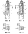
- Controlled burn-through of the seal 9 designed as a lip seal is provided in the embodiment of the belt tightener shown in FIGS. 2 and 3.
- the burn-through takes place at one or more burn-through points 14 of the seal 9.
- these burn-through points form progressively opening gas passageways. Accordingly, the working pressure in the pressure chamber 1 is progressively reduced until the driving part 2 can move, during extraction of belt webbing which is decelerated by the force limiter 4, counter to the driving direction during tightening once the blockable part of the belt reel 3 has been blocked.
- the seal 9 is designed so that propellant gas can flow past the seal after the tightening process, so that a reduction in the working pressure in the pressure chamber 1 is achieved.
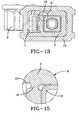
- the material for example aluminum, of which the piston guide 10 consists, is so dimensioned that it can be plastically deformed owing to the excessive working pressure prevailing in the pressure chamber, in particular in the region of the two lateral walls. Gas passageways 19 are then formed between the lateral walls of the guide 10 and the wall of the seal 19 surrounding the piston 2. In this way, the pressure in the pressure chamber 1 is reduced not abruptly as occurs during a rupture process but in a dampened manner within a specific period of time. The desired minimum period after initiation of the working pressure can be used up owing to the correspondingly selected flow properties of the material, until the final gas blowout passageways 19 are formed.
- the piston guide can be formed from an aluminum cold flow molding part.
- a burn-through point 15 is provided in the driving part (piston) 2 in the embodiment shown in FIG. 6.
- the gas blowout passageway desired for the reduction of pressure in the pressure chamber is formed gradually at this point by burning free within a specific period of time.
- the burn-through point 15 is provided on the underside of the piston, i.e. at the front of the piston 2 as viewed in the driving direction. This arrangement of the burn-through point in the driving part is a preferred point.
- Burn-through elements 16 that burn free to form a plurality of gas blowout passageways in the seal 9, which are formed gradually within a specific burnout time, are provided on the seal 9 in the embodiment of FIGS. 8 and 9.
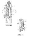
- a burn-through point 17 which forms the delayed pressure reduction in the pressure chamber 1 during the burning free of a gas blowout passageway is provided in the limiting wall of the pressure chamber 1 or of the piston guide 10.
- a pyrotechnic charge can be provided in the burn-through point 15 or 17, for example by pressure insertion, in the embodiment in FIGS. 6 and 7 as well as in the embodiment in FIGS. 10 and 11.
- the burn-through point 17 can also be provided at a different point of the pressure chamber 1 or along the guide path of the driving part 2 during its tightening movement.
- a burn-through point 20 can be provided on a gas generator that is used as propellant gas source 24.
- the gas generator can be designed in the manner shown in FIG. 16.
- the gas generator has an igniter 25, for example in the form of a priming cap, with which a propellant charge 26 is ignited pyrotechnically for producing the propellant gas.
- the igniter 25 can serve to liberate the propellant gas.
- a burnout section through which the minimum time for opening of the burn-through point 20 is determined. The burnout section is ignited simultaneously with the ignition of the propellant charge 26.
- the burnout section can also extend outside the gas generator housing and be guided to a burn-through point 20 provided in the piston guide 10, as in the embodiment in FIGS. 10 and 11. If the gas generator is arranged in the driving part (piston) 2, the burn-through point can also be provided on the piston.
- Timed opening or burning free of the gas blowout passageway can be achieved by means of the burn-out section, independently of the path covered by the driving part during the tightening process. Burning free can be set into operation simultaneously with the activation of the propellant gas, for example during the ignition thereof. A reduction in the working pressure prevailing in the pressure chamber 1 is then achieved irrespective of the working stroke covered by the driving part 2.
- a weak breaking point 18 of the piston material, in particular aluminum, is provided in the piston, which is opened after a time delay after the working stroke of the driving part 2 owing to the working pressure prevailing in the pressure chamber 1 as a result of the flow properties of the material at the weak point.
- the weak point 18 is located at the upper end of the toothed rack 7 in the embodiment illustrated. It is formed at the point where two limiting walls of a cavity 21 formed in the driving part (piston) 2 abut in the piston, belonging to the pressure chamber 1, and form the weak point 18.
- the viscosity of the material of the set breaking point which is plastic at the stresses occurring is so adjusted that a specific period of time elapses before the breakage (tearing).
- the seal 9 in the region of the set breaking point 18 also opens. After the opening of the set breaking point 18, the propellant gas is able to escape or blow out via a gap 22 provided between the toothed rack 7 and piston 2.
- the driving part (piston) 2 is preferably designed as an aluminum die-casting.
- the driving part (piston) 2 as well as the tubular guide 10 have a substantially rectangular cross section.
- the guide 10 is preferably produced from soft metal, in particular aluminum, as a cold flow molding part and can be caused to bulge by the pressure prevailing in the pressure chamber 1 after tightening.
- the gas blowout passageway can be formed between the seal 9 and the internal wall of the tubular piston guide 10 for reducing pressure in the pressure chamber 1.
- a further chamber 27 connected to the pressure chamber 1 is provided in the embodiment shown in FIG. 17.
- This further chamber 27 is sealed by a sealing element 28, for example in the form of a plug. If an excessively high working pressure builds up in the pressure chamber 1 after the tightening process, the plug-like sealing element 28 is moved along a tubular guide section 29 which can be provided on the guide 10, from a corresponding pressure threshold. The space in which the working pressure prevails is therefore enlarged, so that a reduction in pressure is achieved. When the sealing element 28 has left the guide section through the exit at the lower end, complete pressure compensation with the exterior takes place.
- a specific period of time can be adjusted until a gas passageway from the pressure chamber 1 to the exterior is completely cleared.
- a guide section 30 is provided at the lower end of the driving part (piston) 2. This guide section 30 extends from the interior of the piston pertaining to the pressure chamber 1 to the exterior of the piston. This guide section 30 is also sealed by a plug-like sealing element 31. A pressure reduction in the pressure chamber 1 is also achieved during the movement of the sealing element 31 along the guide section 30. After a specific period of time, the sealing element 28 leaves the guide section 30, as in the embodiment in FIG. 17, so that the pressure chamber 1 is cleared completely to the exterior for pressure compensation.
Landscapes
- Engineering & Computer Science (AREA)
- Mechanical Engineering (AREA)
- Automotive Seat Belt Assembly (AREA)
Description
Claims (10)
- A device for restraining a seat belt comprising:characterized in thata belt reel (3) upon which the seat belt (11) can be wound;a belt tightener (5) adapted to be driven by a propellant gas which acts in a driving direction on a movable driving part (2) connected to the belt reel with a working pressure in a pressure chamber (1) during driving;a blocking device (6) for blocking the belt reel; anda pressure-reducing device (14 to 20) suitable to reduce the working pressure in the pressure chamber (1) after tightening the seat belt;the pressure-reducing device (14 to 20) is designed to reduce the working pressure after tightening of the seat belt and after a lapse of a specific period of time within which the blocking device (6) is locking the belt reel (3).
- The device for restraining a seat belt according to claim 1 further comprising a load limiter (4) which cooperates with the belt reel (3) and, after blocking of the belt reel, allows extraction of belt webbing (11) with energy consumption, wherein the driving part (2) remaining in a driving connection with the belt reel (3) can be moved counter to the driving direction when the load limiter is actuated.
- The device for restraining a seat belt according to claim 1 or 2 wherein the pressure-reducing device (14 to 20) is provided on the driving part (2) or in a stationary limit of the pressure chamber (1).
- The device for restraining a seat belt according to one of claims 1 to 3 wherein after expiry of a specific period of time beginning with initiation of the working pressure, the pressure-reducing device (14 to 20) creates a gas blow-out orifice.
- The device for restraining a seat belt according to one of claims 1 to 4 wherein the gas blow-out orifice (14 to 17 and 20) can be cleared by burning.
- The device for restraining a seat belt according to one of claims 1 to 5 wherein the gas blow-out orifice (18) is formed by a weak point of material after a time delay.
- The device for restraining a seat belt according to one of claims 1 to 6 wherein burning is initiated by an igniter (25) which starts up the generation of the propellant gas.
- The device for restraining a seat belt according to claim 5 wherein the minimum time from the moment of release of propellant gas to the opening of the burn-through point (17; 20) can be adjusted by means of the burn-out section.
- The device for restraining a seat belt according to one of claims 1 to 8 wherein the gas blow-out orifice (19) is formed by bulging of material.
- The device for restraining a seat belt according to one of claims 1 to 9 wherein a further chamber (27) sealed from the exterior by a sealing element (28) is connected to the pressure chamber (1), the sealing element (28) being movable to increase the volume and/or to create an orifice at a specific pressure in the pressure chamber (1).
Applications Claiming Priority (3)
| Application Number | Priority Date | Filing Date | Title |
|---|---|---|---|
| DE19927270A DE19927270C2 (en) | 1999-06-15 | 1999-06-15 | Restraint device for a seat belt of a motor vehicle that can be wound onto a belt reel |
| DE19927270 | 1999-06-15 | ||
| PCT/US1999/027745 WO2000076815A1 (en) | 1999-06-15 | 1999-11-22 | Device for restraining a seat belt |
Publications (2)
| Publication Number | Publication Date |
|---|---|
| EP1187742A1 EP1187742A1 (en) | 2002-03-20 |
| EP1187742B1 true EP1187742B1 (en) | 2004-08-18 |
Family
ID=7911305
Family Applications (1)
| Application Number | Title | Priority Date | Filing Date |
|---|---|---|---|
| EP99963949A Expired - Lifetime EP1187742B1 (en) | 1999-06-15 | 1999-11-22 | Device for restraining a seat belt |
Country Status (4)
| Country | Link |
|---|---|
| US (1) | US6299090B1 (en) |
| EP (1) | EP1187742B1 (en) |
| DE (2) | DE19927270C2 (en) |
| WO (1) | WO2000076815A1 (en) |
Families Citing this family (20)
| Publication number | Priority date | Publication date | Assignee | Title |
|---|---|---|---|---|
| DE10027212C2 (en) | 2000-05-31 | 2003-12-18 | Breed Automotive Tech | Device for driving a seat belt pretensioner |
| JP4651841B2 (en) * | 2001-03-22 | 2011-03-16 | オートリブ株式会社 | Seat belt device |
| DE20105264U1 (en) * | 2001-03-26 | 2001-08-09 | TRW Occupant Restraint Systems GmbH & Co. KG, 73553 Alfdorf | Pyrotechnic belt tensioner drive |
| US6698677B1 (en) * | 2002-11-12 | 2004-03-02 | H. Koch & Sons Co., Inc. | Restraint pretensioner |
| DE20303302U1 (en) | 2003-02-28 | 2003-07-10 | TRW Occupant Restraint Systems GmbH & Co. KG, 73553 Alfdorf | Belt retractor with tensioning device |
| DE102004002425A1 (en) * | 2004-01-16 | 2005-08-11 | Trw Occupant Restraint Systems Gmbh & Co. Kg | Belt reel, in particular for belt retractor with belt tensioner |
| US7510597B2 (en) | 2004-03-19 | 2009-03-31 | Shell Oil Company | Method and separator for cyclonic separation of a fluid mixture |
| DE202004009949U1 (en) * | 2004-06-24 | 2004-10-14 | Key Safety Systems, Inc., Lakeland | Vehicle seat belt retractor |
| DE102006022344A1 (en) * | 2006-05-12 | 2007-11-15 | Trw Automotive Gmbh | Linear drive for tightening seat belt, has housing, adjustable piston in housing, pyrotechnic gas producer, pressure chamber, venting hole by which compressed gas from pressure chamber escapes and fusible catch element |
| DE102007037314B4 (en) * | 2007-08-08 | 2009-05-07 | Key Safety Systems, Inc., Sterling Heights | Device for tightening a vehicle seat belt |
| JP5314531B2 (en) | 2008-09-04 | 2013-10-16 | 株式会社東海理化電機製作所 | Pretensioner |
| JP5198983B2 (en) * | 2008-09-04 | 2013-05-15 | 株式会社東海理化電機製作所 | Pretensioner and pretensioner manufacturing method |
| US8585090B2 (en) | 2010-06-29 | 2013-11-19 | Autoliv Asp, Inc. | High efficiency pretensioner |
| DE102010026113B4 (en) * | 2010-07-05 | 2015-03-26 | Autoliv Development Ab | Pyrotechnic belt tensioner for a safety belt system with a force limiting device |
| US8226122B2 (en) | 2010-11-12 | 2012-07-24 | Autoliv Asp, Inc. | Thin linear seatbelt pretensioner |
| DE102010051422A1 (en) * | 2010-11-17 | 2012-05-24 | Trw Automotive Gmbh | Belt tensioner for belt retractor with force limiting device and method for tightening a seat belt and subsequent force limitation |
| KR101176787B1 (en) * | 2010-11-23 | 2012-08-24 | 주식회사 디비아이 | Pretensioner |
| DE102011016153A1 (en) * | 2011-04-05 | 2012-10-11 | Trw Automotive Gmbh | retractor |
| US8528987B2 (en) | 2012-01-30 | 2013-09-10 | Autoliv Asp, Inc. | Linear seat belt pretensioner |
| DE102013210766B4 (en) * | 2013-06-10 | 2017-07-13 | Takata AG | Tensioner drive for a seat belt device |
Family Cites Families (15)
| Publication number | Priority date | Publication date | Assignee | Title |
|---|---|---|---|---|
| FR2167270A5 (en) * | 1972-01-11 | 1973-08-24 | Ferodo Sa | |
| US3942819A (en) * | 1972-05-12 | 1976-03-09 | Volkswagenwerk Aktiengesellschaft | Safety belt tensioning device |
| GB8719415D0 (en) * | 1987-08-17 | 1987-09-23 | Sec Dep For Transport | Seat belt pretensioner |
| EP0360902B1 (en) | 1988-09-29 | 1993-08-18 | Trw Repa Gmbh | Propulsive device for restraint systems in motor vehicles |
| JPH0510131U (en) | 1991-07-25 | 1993-02-09 | 株式会社東海理化電機製作所 | Preloader device |
| DE9304152U1 (en) | 1993-03-20 | 1993-05-13 | TRW Repa GmbH, 7077 Alfdorf | Belt tensioner with pyrotechnic gas generator |
| DE9308273U1 (en) * | 1993-06-02 | 1993-07-29 | HS Technik und Design Technische Entwicklungen GmbH, 82234 Weßling | Device for the pyrotechnic rotary drive of a winding shaft of a safety belt retractor |
| DE4426479C2 (en) * | 1994-07-26 | 1999-01-07 | Hs Tech & Design | Seat belt restraint system |
| GB2306409B (en) * | 1995-10-23 | 1999-05-26 | Autoliv Dev | Improvements in or relating to an air-bag arrangement |
| DE19545795C1 (en) * | 1995-12-08 | 1997-03-20 | Autoliv Dev | Pyrotechnic safety-belt-tightening mechanism |
| DE29520307U1 (en) | 1995-12-21 | 1996-04-18 | Trw Occupant Restraint Systems Gmbh, 73551 Alfdorf | Linear drive for a belt tensioner |
| JP3218987B2 (en) * | 1996-08-29 | 2001-10-15 | 日本精工株式会社 | Pretensioner for seat belt retractor |
| US5871236A (en) * | 1997-05-13 | 1999-02-16 | Trw Vehicle Safety Systems Inc. | Apparatus for pretensioning seat belt webbing |
| JP3452779B2 (en) * | 1997-11-28 | 2003-09-29 | 株式会社東海理化電機製作所 | Rotation amount limiting device and webbing take-up device |
| GB2332397B (en) * | 1997-12-18 | 2002-02-27 | Breed Automotive Technologies | Retractor for use with seat belt pretensioner |
-
1999
- 1999-06-15 DE DE19927270A patent/DE19927270C2/en not_active Expired - Fee Related
- 1999-11-22 WO PCT/US1999/027745 patent/WO2000076815A1/en not_active Ceased
- 1999-11-22 EP EP99963949A patent/EP1187742B1/en not_active Expired - Lifetime
- 1999-11-22 DE DE69919596T patent/DE69919596D1/en not_active Expired - Lifetime
- 1999-11-24 US US09/448,261 patent/US6299090B1/en not_active Expired - Fee Related
Also Published As
| Publication number | Publication date |
|---|---|
| EP1187742A1 (en) | 2002-03-20 |
| WO2000076815A1 (en) | 2000-12-21 |
| DE19927270C2 (en) | 2002-07-11 |
| DE19927270A1 (en) | 2001-01-04 |
| US6299090B1 (en) | 2001-10-09 |
| DE69919596D1 (en) | 2004-09-23 |
Similar Documents
| Publication | Publication Date | Title |
|---|---|---|
| US6299090B1 (en) | Device for restraining a seat belt | |
| US5956954A (en) | Linear drive for a belt tensioner | |
| EP3595939B1 (en) | Seatbelt pretensioning retractor assembly including a gas release opening | |
| US5899488A (en) | Air bag arrangement and triggering process therefor | |
| EP3595941B1 (en) | Seatbelt pretensioning retractor assembly including a piston-safety valve member | |
| US5397075A (en) | Seat belt pretensioner | |
| EP1286866B1 (en) | Seat belt pretensioner | |
| JP3218987B2 (en) | Pretensioner for seat belt retractor | |
| CZ373396A3 (en) | Linear drive for belt tightening mechanism | |
| US6994288B2 (en) | Belt retractor comprising a tensioning device | |
| US6149095A (en) | Device for tightening a seatbelt | |
| US6871877B2 (en) | Safety belt apparatus | |
| JP2002514549A (en) | Safety steering column, vehicle safety system and vehicle with safety system and safety method | |
| US20010035643A1 (en) | Operating system and process for safety devices in a vehicle | |
| US5772246A (en) | Mechanical shock reduction in pretensioners | |
| JP3886828B2 (en) | Seat belt retractor pretensioner | |
| US8231073B2 (en) | Load limiting seat belt retractor | |
| US20030122363A1 (en) | Operating method and system for vehicle safety device | |
| JP4278818B2 (en) | Webbing retractor and vehicle | |
| JPS6238843Y2 (en) | ||
| KR100535003B1 (en) | Pretensioner for seat belt of vehicle | |
| JP2014088063A (en) | Retractor for seat belt | |
| JP2014088061A (en) | Retractor for seat belt |
Legal Events
| Date | Code | Title | Description |
|---|---|---|---|
| PUAI | Public reference made under article 153(3) epc to a published international application that has entered the european phase |
Free format text: ORIGINAL CODE: 0009012 |
|
| 17P | Request for examination filed |
Effective date: 20011002 |
|
| AK | Designated contracting states |
Kind code of ref document: A1 Designated state(s): AT BE CH CY DE DK ES FI FR GB GR IE IT LI LU MC NL PT SE |
|
| RAP3 | Party data changed (applicant data changed or rights of an application transferred) |
Owner name: BREED AUTOMOTIVE TECHNOLOGY, INC. |
|
| 17Q | First examination report despatched |
Effective date: 20030425 |
|
| GRAP | Despatch of communication of intention to grant a patent |
Free format text: ORIGINAL CODE: EPIDOSNIGR1 |
|
| RAP1 | Party data changed (applicant data changed or rights of an application transferred) |
Owner name: KEY SAFETY SYSTEMS, INC. |
|
| GRAS | Grant fee paid |
Free format text: ORIGINAL CODE: EPIDOSNIGR3 |
|
| GRAA | (expected) grant |
Free format text: ORIGINAL CODE: 0009210 |
|
| AK | Designated contracting states |
Kind code of ref document: B1 Designated state(s): DE FR GB IT |
|
| REG | Reference to a national code |
Ref country code: GB Ref legal event code: FG4D |
|
| REG | Reference to a national code |
Ref country code: IE Ref legal event code: FG4D |
|
| REF | Corresponds to: |
Ref document number: 69919596 Country of ref document: DE Date of ref document: 20040923 Kind code of ref document: P |
|
| PG25 | Lapsed in a contracting state [announced via postgrant information from national office to epo] |
Ref country code: DE Free format text: LAPSE BECAUSE OF FAILURE TO SUBMIT A TRANSLATION OF THE DESCRIPTION OR TO PAY THE FEE WITHIN THE PRESCRIBED TIME-LIMIT Effective date: 20041119 |
|
| ET | Fr: translation filed | ||
| PLBE | No opposition filed within time limit |
Free format text: ORIGINAL CODE: 0009261 |
|
| STAA | Information on the status of an ep patent application or granted ep patent |
Free format text: STATUS: NO OPPOSITION FILED WITHIN TIME LIMIT |
|
| 26N | No opposition filed |
Effective date: 20050519 |
|
| PGFP | Annual fee paid to national office [announced via postgrant information from national office to epo] |
Ref country code: IT Payment date: 20071114 Year of fee payment: 9 |
|
| PGFP | Annual fee paid to national office [announced via postgrant information from national office to epo] |
Ref country code: GB Payment date: 20071005 Year of fee payment: 9 Ref country code: FR Payment date: 20071105 Year of fee payment: 9 |
|
| GBPC | Gb: european patent ceased through non-payment of renewal fee |
Effective date: 20081122 |
|
| PG25 | Lapsed in a contracting state [announced via postgrant information from national office to epo] |
Ref country code: IT Free format text: LAPSE BECAUSE OF NON-PAYMENT OF DUE FEES Effective date: 20081122 |
|
| REG | Reference to a national code |
Ref country code: FR Ref legal event code: ST Effective date: 20090731 |
|
| PG25 | Lapsed in a contracting state [announced via postgrant information from national office to epo] |
Ref country code: GB Free format text: LAPSE BECAUSE OF NON-PAYMENT OF DUE FEES Effective date: 20081122 |
|
| PG25 | Lapsed in a contracting state [announced via postgrant information from national office to epo] |
Ref country code: FR Free format text: LAPSE BECAUSE OF NON-PAYMENT OF DUE FEES Effective date: 20081130 |