EP1187185A1 - Hot plate unit - Google Patents
Hot plate unit Download PDFInfo
- Publication number
- EP1187185A1 EP1187185A1 EP00981826A EP00981826A EP1187185A1 EP 1187185 A1 EP1187185 A1 EP 1187185A1 EP 00981826 A EP00981826 A EP 00981826A EP 00981826 A EP00981826 A EP 00981826A EP 1187185 A1 EP1187185 A1 EP 1187185A1
- Authority
- EP
- European Patent Office
- Prior art keywords
- hot plate
- casing
- air
- space
- plate unit
- Prior art date
- Legal status (The legal status is an assumption and is not a legal conclusion. Google has not performed a legal analysis and makes no representation as to the accuracy of the status listed.)
- Withdrawn
Links
Images



Classifications
-
- H—ELECTRICITY
- H10—SEMICONDUCTOR DEVICES; ELECTRIC SOLID-STATE DEVICES NOT OTHERWISE PROVIDED FOR
- H10P—GENERIC PROCESSES OR APPARATUS FOR THE MANUFACTURE OR TREATMENT OF DEVICES COVERED BY CLASS H10
- H10P72/00—Handling or holding of wafers, substrates or devices during manufacture or treatment thereof
- H10P72/04—Apparatus for manufacture or treatment
- H10P72/0431—Apparatus for thermal treatment
- H10P72/0434—Apparatus for thermal treatment mainly by convection
-
- H—ELECTRICITY
- H05—ELECTRIC TECHNIQUES NOT OTHERWISE PROVIDED FOR
- H05B—ELECTRIC HEATING; ELECTRIC LIGHT SOURCES NOT OTHERWISE PROVIDED FOR; CIRCUIT ARRANGEMENTS FOR ELECTRIC LIGHT SOURCES, IN GENERAL
- H05B3/00—Ohmic-resistance heating
- H05B3/10—Heating elements characterised by the composition or nature of the materials or by the arrangement of the conductor
- H05B3/12—Heating elements characterised by the composition or nature of the materials or by the arrangement of the conductor characterised by the composition or nature of the conductive material
- H05B3/14—Heating elements characterised by the composition or nature of the materials or by the arrangement of the conductor characterised by the composition or nature of the conductive material the material being non-metallic
- H05B3/141—Conductive ceramics, e.g. metal oxides, metal carbides, barium titanate, ferrites, zirconia, vitrous compounds
- H05B3/143—Conductive ceramics, e.g. metal oxides, metal carbides, barium titanate, ferrites, zirconia, vitrous compounds applied to semiconductors, e.g. wafers heating
-
- H—ELECTRICITY
- H05—ELECTRIC TECHNIQUES NOT OTHERWISE PROVIDED FOR
- H05B—ELECTRIC HEATING; ELECTRIC LIGHT SOURCES NOT OTHERWISE PROVIDED FOR; CIRCUIT ARRANGEMENTS FOR ELECTRIC LIGHT SOURCES, IN GENERAL
- H05B3/00—Ohmic-resistance heating
- H05B3/20—Heating elements having extended surface area substantially in a two-dimensional [2D] plane, e.g. plate-heater
- H05B3/22—Heating elements having extended surface area substantially in a two-dimensional [2D] plane, e.g. plate-heater non-flexible
- H05B3/26—Heating elements having extended surface area substantially in a two-dimensional [2D] plane, e.g. plate-heater non-flexible heating conductor mounted on insulating base
-
- H—ELECTRICITY
- H05—ELECTRIC TECHNIQUES NOT OTHERWISE PROVIDED FOR
- H05B—ELECTRIC HEATING; ELECTRIC LIGHT SOURCES NOT OTHERWISE PROVIDED FOR; CIRCUIT ARRANGEMENTS FOR ELECTRIC LIGHT SOURCES, IN GENERAL
- H05B3/00—Ohmic-resistance heating
- H05B3/68—Heating arrangements specially adapted for cooking plates or analogous hot-plates
-
- H—ELECTRICITY
- H05—ELECTRIC TECHNIQUES NOT OTHERWISE PROVIDED FOR
- H05B—ELECTRIC HEATING; ELECTRIC LIGHT SOURCES NOT OTHERWISE PROVIDED FOR; CIRCUIT ARRANGEMENTS FOR ELECTRIC LIGHT SOURCES, IN GENERAL
- H05B3/00—Ohmic-resistance heating
- H05B3/68—Heating arrangements specially adapted for cooking plates or analogous hot-plates
- H05B3/74—Non-metallic plates, e.g. vitroceramic, ceramic or glassceramic hobs, also including power or control circuits
-
- H—ELECTRICITY
- H10—SEMICONDUCTOR DEVICES; ELECTRIC SOLID-STATE DEVICES NOT OTHERWISE PROVIDED FOR
- H10P—GENERIC PROCESSES OR APPARATUS FOR THE MANUFACTURE OR TREATMENT OF DEVICES COVERED BY CLASS H10
- H10P72/00—Handling or holding of wafers, substrates or devices during manufacture or treatment thereof
- H10P72/04—Apparatus for manufacture or treatment
- H10P72/0431—Apparatus for thermal treatment
- H10P72/0432—Apparatus for thermal treatment mainly by conduction
-
- H—ELECTRICITY
- H05—ELECTRIC TECHNIQUES NOT OTHERWISE PROVIDED FOR
- H05B—ELECTRIC HEATING; ELECTRIC LIGHT SOURCES NOT OTHERWISE PROVIDED FOR; CIRCUIT ARRANGEMENTS FOR ELECTRIC LIGHT SOURCES, IN GENERAL
- H05B2203/00—Aspects relating to Ohmic resistive heating covered by group H05B3/00
- H05B2203/002—Heaters using a particular layout for the resistive material or resistive elements
-
- H—ELECTRICITY
- H05—ELECTRIC TECHNIQUES NOT OTHERWISE PROVIDED FOR
- H05B—ELECTRIC HEATING; ELECTRIC LIGHT SOURCES NOT OTHERWISE PROVIDED FOR; CIRCUIT ARRANGEMENTS FOR ELECTRIC LIGHT SOURCES, IN GENERAL
- H05B2203/00—Aspects relating to Ohmic resistive heating covered by group H05B3/00
- H05B2203/013—Heaters using resistive films or coatings
-
- H—ELECTRICITY
- H05—ELECTRIC TECHNIQUES NOT OTHERWISE PROVIDED FOR
- H05B—ELECTRIC HEATING; ELECTRIC LIGHT SOURCES NOT OTHERWISE PROVIDED FOR; CIRCUIT ARRANGEMENTS FOR ELECTRIC LIGHT SOURCES, IN GENERAL
- H05B2203/00—Aspects relating to Ohmic resistive heating covered by group H05B3/00
- H05B2203/016—Heaters using particular connecting means
-
- H—ELECTRICITY
- H05—ELECTRIC TECHNIQUES NOT OTHERWISE PROVIDED FOR
- H05B—ELECTRIC HEATING; ELECTRIC LIGHT SOURCES NOT OTHERWISE PROVIDED FOR; CIRCUIT ARRANGEMENTS FOR ELECTRIC LIGHT SOURCES, IN GENERAL
- H05B2203/00—Aspects relating to Ohmic resistive heating covered by group H05B3/00
- H05B2203/017—Manufacturing methods or apparatus for heaters
Definitions
- the present invention relates to a hot plate unit, and more particularly, to a hot plate unit used to heat silicon wafers during a semiconductor manufacturing process.
- a heating apparatus which is normally referred to as a hot plate unit, is used.
- Japanese Examined Patent Publication No. 4-13837 describes a prior art example of such apparatus.
- the heating apparatus of the publication includes a hot plate, which functions as an electric heating member and is made of sintered aluminum nitride, and a resistor, which is arranged in the plate.
- the resistor is held between ceramic base materials, which form the hot plate.
- the resistor has two ends that project from the side of the hot plate and are connected to a power supply via a power line.
- a silicon wafer which is a heated subject, is placed on an upper surface of the hot plate.
- the resistor is energized in this state, the silicon wafer is heated to a predetermined temperature (e.g., several hundred degrees).
- the hot plate When the resistor is energized for a predetermined time to dry photosensitive resin, the hot plate is first cooled to a relatively low temperature. Then, the silicon wafer is removed from the hot plate. However, a relatively long time is necessary for the cooling. This limits productivity.
- a cooling pipe through which a coolant flows may be arranged on the lower surface of the plate to forcibly cool the plate and shorten the cooling time.
- this not only causes the entire unit to have a complicated structure but also causes the unit to be bulky and large.
- air may be forced against the lower surface of the hot plate to cool the plate and shorten the cooling time. However, this may contaminate the periphery of the apparatus with moisture and dust that are included in the air.
- a perspective of the present invention proposes a hot plate unit, which is arranged in an opened portion of a casing and has a resistor.
- a space for enabling the circulation of fluid is formed by the casing and the hot plate and an inner bottom plate is provided in the casing.
- an opening be formed in the inner bottom plate.
- a fluid circulates in the space formed by the casing and the hot plate. This enables forced cooling of the hot plate and shortens the cooling time in comparison to natural cooling. Further, since cooling pipes are not required, there is no need for concern of the structure of the entire unit becoming complicated or bulky.
- a hot plate unit 1 according to a first embodiment of the present invention will now be described with reference to Figs. 1 and 2.
- a hot plate unit 1 which is shown in Figs. 1 and 2, is formed by the main elements of a casing 2 and a hot plate 3.
- the casing 2 is a cup-like metal member (aluminum member) having an opened portion 4, the cross-section of which is round, located at its upper portion.
- Pin insertion sleeves 5, each of which receives a lift pin (not shown), are arranged near the center of a bottom portion 2a at three positions. The lift pins lifts a silicon wafer W1 in a state supporting the silicon wafer W1 at three points.
- the hot plate 3 is a low-temperature hot plate that heats the silicon wafer W, to which a photosensitive resin is applied, to 200 to 300°C and dries the silicon wafer W.
- the hot plate 3 is formed by attaching a wiring resistor 10, which serves as a resistor, to a plate-like base material 9, which is made of a sintered ceramic.
- the plate-like base material 9 is arranged on the opened portion 4, and a seal ring 14, which will be described later, is arranged between the casing 2 and the base material 9. This arrangement forms a generally sealed space S1 within the inner side of the casing 2 and the lower surface of the hot plate 3.
- the thickness of the unit 1 be 5mm to 100mm and particularly preferred that the thickness be 10mm to 50mm. This is because, if the unit 1 becomes too thick, the apparatus will be bulky. On the other hand, the hot plate 3 and the casing 2 must be thin to make the unit 1 thin. This may cause manufacturing to be difficult. Accordingly, the thickness of the unit 1 is 20mm.
- the plate-like base material 9 is disk-like.
- the diameter of the plate-like base material 9 is slightly smaller than the external dimension of the casing 2.
- the wiring resistor 10 is formed in a concentric or spiral manner on the lower surface of the plate-like base material 9.
- Lift pin holes 11 are formed in the central portion of the hot plate 3 at positions corresponding to the sleeves.
- nitride ceramic sinter which has superior heat resistance and high heat conductivity characteristics, be selected as the material of the plate-like base material 9. It is preferred that the nitride ceramic sinter be a sinter formed from a metal nitride sinter, such as aluminum nitride, silicon nitride, boron nitride, and titanium nitride. Aluminum nitride sinter is especially preferred. This is because aluminum nitride sinter has the highest heat conductivity among these sinters. A sinter formed from a metal carbide ceramic, such as silicon carbide, zirconium carbide, titanium carbide, tantalum carbide, and tungsten carbide, may also be used.
- a metal carbide ceramic such as silicon carbide, zirconium carbide, titanium carbide, tantalum carbide, and tungsten carbide, may also be used.
- the wiring resistor 10 is formed by fusing a conductive paste to the plate-like base material 9.
- the conductive paste includes metal particles, a metal oxide, a resin, and a solvent.
- Preferred metal particles that are used as the conductive paste are, for example, gold, silver, platinum, palladium, lead, tungsten, and nickel. These metals are preferred because they withstand oxidation even under high temperatures and because their resistances are such that they are easily heated when energized.
- Preferred metal oxides for the conductive paste are, for example, lead oxide, zinc oxide, silica, boron oxide, alumina, yttria, and titania.
- pads 10a which serve as external connection terminals, are formed on the ends of the wiring resistor 10.
- a terminal pin 12 is soldered to each pad 10a. This electrically connects the terminal pins 12 to the wiring resistor 10.
- a socket 6a located on the distal end of each lead wire 6 is fitted to the distal end of each terminal pin 12. Accordingly, when current is supplied via the lead wires 6 and the terminal pins 12, the temperature of the wiring resistor 10 increases and heats the entire hot plate 3.
- the seal ring 14 which serves as a seal element, is arranged on the top rim of the opened portion 4.
- the seal ring 14 is annular and is substantially the same size as the opened portion 4. It is preferred that the seal ring 14 be made of an elastic material, such as resin or rubber.
- the seal ring 14 has a plurality of threaded holes 15 corresponding to the plurality of threaded holes 13.
- a stepped support 16 is formed on the inner wall of the seal ring 14 to-support the lower surface of the hot plate 3 in a horizontal manner. When the hot plate 3 is supported by the stepped support 16, the top surface of the seal ring 14 is flush with the upper surface of the hot plate 3.
- the seal ring 14 seals the space between the top rim of the opened portion 4 and the lower peripheral surface of the hot plate 3. This hinders the flow of air through the space.
- a holding ring 21 is fixed to the upper surface of the seal ring 14 by bolts 25.
- the holding ring 21 includes an annular body 22, a plurality of threaded holes 23, and a plurality of holding tabs 24.
- the holding tabs 24 press the hot plate 3, which rests on the stepped support 16, in the vertical direction to clamp the seal ring 14.
- a fluid supply port 17 and a fluid discharge port 18 are each attached to the bottom portion 2a by a bolt or the like.
- the ports 17, 18 are spaced apart from each other.
- the ports 17, 18 have passages extending between their inner and outer ends. Thus, the interior and exterior of the casing 2 are connected through the passages.
- a female thread is formed in the inner surface of the outer end of the fluid supply port 17 about the opening to detachably receive one end of a fluid supply pipe (not shown).
- the other end of the pipe is connected to a fluid supply pump.
- air is supplied through the pipe as a cooling fluid.
- a female thread is also formed in the inner surface of the outer end side of the fluid discharge port 18 about the opening to detachably receive one end of a fluid discharge pipe (not shown).
- the air in the casing 2 is discharged externally through the pipe.
- the other end of the pipe opens at a location relatively distant from the apparatus.
- a seal packing 8 which serves as a seal structure, is fitted into the lead wire hole 7.
- the seal packing 8 is an annular elastic body made of rubber or the like.
- Each lead wire 6 is inserted through a through hole of the seal packing 8 and extended out of the casing 2.
- the seal packing 8 seals the space between each lead wire 6 and the lead wire hole 7 and functions to prevent air from flowing through the space between the lead wires 6 and the lead line hole 7.
- the wiring resistor 10 is energized.
- the contact between the heated hot plate 3 and the silicon wafer W1 gradually increases the temperature of the silicon wafer W1.
- the heating continues for a predetermined time.
- the wiring resistor 10 is de-energized.
- the gas pump is driven to supply the sealed space S1 with cooling air through the fluid supply port 17.
- the air drawn through the fluid supply port 17 contacts the lower surface of the hot plate 3 in the sealed space S1 as it flows toward the fluid discharge port 18.
- the air is heated by the heat of the hot plate 3.
- the air flows out of the space through fluid discharge port 18 and is released to a separate space where there is no worry of contamination.
- the bold arrows of Fig. 1 schematically show the flow of the cooling air.
- the first embodiment has the advantages described below.
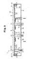
- Fig. 3 is a schematic cross-sectional view showing a hot plate unit 1 according to a second embodiment of the present invention.
- the fluid discharge port 18 is eliminated from the casing 2 and only a ventilation hole 31 is provided.
- the interior of the unit 1 does not have to be in a generally sealed state like in the first embodiment (i.e., the space may be in an opened state). This structure decreases the number of parts and simplifies the structure of the unit 1.
- Fig. 4 is a schematic cross-sectional view showing a hot plate unit 1 according to a third embodiment of the present invention.
- Casing 2A is a metal member (aluminum member) and does not have a bottom portion.
- An opened portion 4 having a round cross-section is formed on the upper portion of the casing 2A.
- An inner bottom plate 41 which is made from metal, is arranged in the casing 2A.
- the inner bottom plate 41 may also be formed from a material other than metal (e.g., ceramic).
- a ventilation hole 31 is preferably formed in the inner bottom plate 41.
- the inner bottom plate 41 is fixed to the upper surface of a fixing portion 45 of the casing 2A.
- the space S1 formed in the casing 2A is not sealed. Accordingly, air is permitted to escape outside through the gap between the casing 2A and the inner bottom plate 41.
- An opening may be formed in the inner bottom plate 41.
- a fluid supply port 17 is attached to the inner bottom plate 41 using, for example, bolts.
- the port 17 includes a flow passage that opens at the inner end surface and the outer end surface.
- the inner and outer side of the casing 2A is connected by the flow passage.
- the hot plate 3 was manufactured through procedures (1) to (8).
- the hot plate 3 was contacted with an aluminum plate having an air flow passage therein. This was used as a comparative example. After heating the comparative example to a temperature of 140°C, the cooling time required for the temperature to fall to 90°C was measured. The time was eight minutes. In other words, cooling took two times or longer than in the preferred embodiment.
- the third embodiment has the advantages described below.
- the present invention may be modified as described below.
- the seal ring 14 may be deleted.
- the holding ring 21 may be directly fastened to the upper surface at the opened portion 4 of the casing 2 or 2A by bolts, and the hot plate 3 may be engaged with the opened portion 4 in this state. That is, the hot plate 3 may be directly fastened to the casing 2 or 2A.
- the lead wire hole 7, which serves as a wire extending portion, may be arranged in a location other than the bottom portion 2a of the casing 2 such as the side walls of the casing 2 or 2A.
- the ports 17, 18 may be arranged in the side walls of the casings 2 or 2A. The number of the lead wire hole 7 and the ports 17, 18 may of course be increased or decreased when necessary.
- a gas other then air for example, an inert gas such as carbonic acid gas or nitrogen may be circulated as the cooling fluid in the sealed space S1 defined in the casing 2 or 2A. Further, a liquid may also be circulated as the cooling fluid as long as it does not affect the electric structure in an undesirable manner.
- an inert gas such as carbonic acid gas or nitrogen
- a liquid may also be circulated as the cooling fluid as long as it does not affect the electric structure in an undesirable manner.
- thermocouple may be embedded in the plate-like base material 9, which forms the hot plate 3, when necessary. This is to control temperature by measuring the temperature of the hot plate 3 with the thermocouple and changing the voltage value and the current value based on the data. In this case, a lead wire of the thermocouple is extended out of the casing through the seal packing 8.
Landscapes
- Chemical & Material Sciences (AREA)
- Engineering & Computer Science (AREA)
- Ceramic Engineering (AREA)
- Exposure Of Semiconductors, Excluding Electron Or Ion Beam Exposure (AREA)
- Resistance Heating (AREA)
Abstract
A hot plate unit that cools within a short period of time without a complicated or enlarged structure. The hot plate unit (1) includes a hot plate (3), which is arranged in an opened portion (4) of a casing (2A) and has a resistor (10). The casing (2A) and the hot plate (3) form a space to enable the circulation of air. An inner bottom plate (41) is provided in the casing (2A). <IMAGE>
Description
The present invention relates to a hot plate unit, and
more particularly, to a hot plate unit used to heat silicon
wafers during a semiconductor manufacturing process.
During a semiconductor manufacturing process, for
example, when heating and drying a silicon wafer subsequent
to the application of a photosensitive resin, a heating
apparatus, which is normally referred to as a hot plate unit,
is used.
For example, Japanese Examined Patent Publication No.
4-13837 describes a prior art example of such apparatus. The
heating apparatus of the publication includes a hot plate,
which functions as an electric heating member and is made of
sintered aluminum nitride, and a resistor, which is arranged
in the plate. The resistor is held between ceramic base
materials, which form the hot plate. The resistor has two
ends that project from the side of the hot plate and are
connected to a power supply via a power line.
A silicon wafer, which is a heated subject, is placed
on an upper surface of the hot plate. When the resistor is
energized in this state, the silicon wafer is heated to a
predetermined temperature (e.g., several hundred degrees).
When the resistor is energized for a predetermined
time to dry photosensitive resin, the hot plate is first
cooled to a relatively low temperature. Then, the silicon
wafer is removed from the hot plate. However, a relatively
long time is necessary for the cooling. This limits
productivity.
Thus, for example, a cooling pipe through which a
coolant flows may be arranged on the lower surface of the
plate to forcibly cool the plate and shorten the cooling
time. However, this not only causes the entire unit to have
a complicated structure but also causes the unit to be bulky
and large.
Further, air may be forced against the lower surface
of the hot plate to cool the plate and shorten the cooling
time. However, this may contaminate the periphery of the
apparatus with moisture and dust that are included in the
air.
It is an object of the present invention to provide a
hot plate unit that cools within a relatively short period
of time without a complicated or enlarged structure.
A perspective of the present invention proposes a hot
plate unit, which is arranged in an opened portion of a
casing and has a resistor. A space for enabling the
circulation of fluid is formed by the casing and the hot
plate and an inner bottom plate is provided in the casing.
It is preferable that an opening be formed in the
inner bottom plate.
In the present invention, a fluid circulates in the
space formed by the casing and the hot plate. This enables
forced cooling of the hot plate and shortens the cooling
time in comparison to natural cooling. Further, since
cooling pipes are not required, there is no need for concern
of the structure of the entire unit becoming complicated or
bulky.
A hot plate unit 1 according to a first embodiment of
the present invention will now be described with reference
to Figs. 1 and 2.
A hot plate unit 1, which is shown in Figs. 1 and 2,
is formed by the main elements of a casing 2 and a hot plate
3.
The casing 2 is a cup-like metal member (aluminum
member) having an opened portion 4, the cross-section of
which is round, located at its upper portion. Pin insertion
sleeves 5, each of which receives a lift pin (not shown),
are arranged near the center of a bottom portion 2a at three
positions. The lift pins lifts a silicon wafer W1 in a state
supporting the silicon wafer W1 at three points. A lead wire
hole 7 for receiving lead wires 6, which supply current to
the hot plate 3, extends through a peripheral portion of the
bottom portion 2a.
The hot plate 3 is a low-temperature hot plate that
heats the silicon wafer W, to which a photosensitive resin
is applied, to 200 to 300°C and dries the silicon wafer W.
The hot plate 3 is formed by attaching a wiring resistor 10,
which serves as a resistor, to a plate-like base material 9,
which is made of a sintered ceramic. The plate-like base
material 9 is arranged on the opened portion 4, and a seal
ring 14, which will be described later, is arranged between
the casing 2 and the base material 9. This arrangement forms
a generally sealed space S1 within the inner side of the
casing 2 and the lower surface of the hot plate 3.
It is preferred that the thickness of the unit 1 be
5mm to 100mm and particularly preferred that the thickness
be 10mm to 50mm. This is because, if the unit 1 becomes too
thick, the apparatus will be bulky. On the other hand, the
hot plate 3 and the casing 2 must be thin to make the unit 1
thin. This may cause manufacturing to be difficult.
Accordingly, the thickness of the unit 1 is 20mm.
As shown in Fig. 1, the plate-like base material 9 is
disk-like. The diameter of the plate-like base material 9 is
slightly smaller than the external dimension of the casing 2.
The wiring resistor 10 is formed in a concentric or spiral
manner on the lower surface of the plate-like base material
9. Lift pin holes 11 are formed in the central portion of
the hot plate 3 at positions corresponding to the sleeves.
It is preferred that nitride ceramic sinter, which has
superior heat resistance and high heat conductivity
characteristics, be selected as the material of the plate-like
base material 9. It is preferred that the nitride
ceramic sinter be a sinter formed from a metal nitride
sinter, such as aluminum nitride, silicon nitride, boron
nitride, and titanium nitride. Aluminum nitride sinter is
especially preferred. This is because aluminum nitride
sinter has the highest heat conductivity among these sinters.
A sinter formed from a metal carbide ceramic, such as
silicon carbide, zirconium carbide, titanium carbide,
tantalum carbide, and tungsten carbide, may also be used.
The wiring resistor 10 is formed by fusing a
conductive paste to the plate-like base material 9. The
conductive paste includes metal particles, a metal oxide, a
resin, and a solvent. Preferred metal particles that are
used as the conductive paste are, for example, gold, silver,
platinum, palladium, lead, tungsten, and nickel. These
metals are preferred because they withstand oxidation even
under high temperatures and because their resistances are
such that they are easily heated when energized. Preferred
metal oxides for the conductive paste are, for example, lead
oxide, zinc oxide, silica, boron oxide, alumina, yttria, and
titania.
Referring to Fig. 2, pads 10a, which serve as external
connection terminals, are formed on the ends of the wiring
resistor 10. A terminal pin 12 is soldered to each pad 10a.
This electrically connects the terminal pins 12 to the
wiring resistor 10. A socket 6a located on the distal end of
each lead wire 6 is fitted to the distal end of each
terminal pin 12. Accordingly, when current is supplied via
the lead wires 6 and the terminal pins 12, the temperature
of the wiring resistor 10 increases and heats the entire hot
plate 3.
With reference to Fig. 2, equally spaced threaded
holes 13 extend through the top rim of the opened end
portion 4. The seal ring 14, which serves as a seal element,
is arranged on the top rim of the opened portion 4. The seal
ring 14 is annular and is substantially the same size as the
opened portion 4. It is preferred that the seal ring 14 be
made of an elastic material, such as resin or rubber. The
seal ring 14 has a plurality of threaded holes 15
corresponding to the plurality of threaded holes 13. A
stepped support 16 is formed on the inner wall of the seal
ring 14 to-support the lower surface of the hot plate 3 in a
horizontal manner. When the hot plate 3 is supported by the
stepped support 16, the top surface of the seal ring 14 is
flush with the upper surface of the hot plate 3.
The seal ring 14 seals the space between the top rim
of the opened portion 4 and the lower peripheral surface of
the hot plate 3. This hinders the flow of air through the
space.
Referring to Figs. 1 and 2, a holding ring 21 is fixed
to the upper surface of the seal ring 14 by bolts 25. The
holding ring 21 includes an annular body 22, a plurality of
threaded holes 23, and a plurality of holding tabs 24. The
holding tabs 24 press the hot plate 3, which rests on the
stepped support 16, in the vertical direction to clamp the
seal ring 14.
Referring to Fig. 1, a fluid supply port 17 and a
fluid discharge port 18 are each attached to the bottom
portion 2a by a bolt or the like. The ports 17, 18 are
spaced apart from each other. The ports 17, 18 have passages
extending between their inner and outer ends. Thus, the
interior and exterior of the casing 2 are connected through
the passages.
A female thread is formed in the inner surface of the
outer end of the fluid supply port 17 about the opening to
detachably receive one end of a fluid supply pipe (not
shown). The other end of the pipe is connected to a fluid
supply pump. Thus, air is supplied through the pipe as a
cooling fluid. Further, a female thread is also formed in
the inner surface of the outer end side of the fluid
discharge port 18 about the opening to detachably receive
one end of a fluid discharge pipe (not shown). The air in
the casing 2 is discharged externally through the pipe. The
other end of the pipe opens at a location relatively distant
from the apparatus.
Referring to Fig. 2, a seal packing 8, which serves as
a seal structure, is fitted into the lead wire hole 7. The
seal packing 8 is an annular elastic body made of rubber or
the like. Each lead wire 6 is inserted through a through
hole of the seal packing 8 and extended out of the casing 2.
The seal packing 8 seals the space between each lead wire 6
and the lead wire hole 7 and functions to prevent air from
flowing through the space between the lead wires 6 and the
lead line hole 7.
The procedure for using the hot plate unit 1 will now
be discussed.
A silicon wafer W1, to which a photosensitive resin
has been applied, is placed on the hot plate 3. In this
state, the wiring resistor 10 is energized. The contact
between the heated hot plate 3 and the silicon wafer W1
gradually increases the temperature of the silicon wafer W1.
The heating continues for a predetermined time. After the
photosensitive resin is sufficiently dried, the wiring
resistor 10 is de-energized.
Then, the gas pump is driven to supply the sealed
space S1 with cooling air through the fluid supply port 17.
The air drawn through the fluid supply port 17 contacts the
lower surface of the hot plate 3 in the sealed space S1 as
it flows toward the fluid discharge port 18. During this
period, the air is heated by the heat of the hot plate 3.
After being heated, the air flows out of the space through
fluid discharge port 18 and is released to a separate space
where there is no worry of contamination. The bold arrows of
Fig. 1 schematically show the flow of the cooling air. When
the hot plate 3 is cooled to a relatively low temperature,
the silicon wafer W1 is removed from the hot plate 3.
The first embodiment has the advantages described
below.
Fig. 3 is a schematic cross-sectional view showing a
hot plate unit 1 according to a second embodiment of the
present invention. In the second embodiment, the fluid
discharge port 18 is eliminated from the casing 2 and only a
ventilation hole 31 is provided. In other words, the
interior of the unit 1 does not have to be in a generally
sealed state like in the first embodiment (i.e., the space
may be in an opened state). This structure decreases the
number of parts and simplifies the structure of the unit 1.
Fig. 4 is a schematic cross-sectional view showing a
hot plate unit 1 according to a third embodiment of the
present invention. Casing 2A is a metal member (aluminum
member) and does not have a bottom portion. An opened
portion 4 having a round cross-section is formed on the
upper portion of the casing 2A. An inner bottom plate 41,
which is made from metal, is arranged in the casing 2A. The
inner bottom plate 41 may also be formed from a material
other than metal (e.g., ceramic). Further, as shown in Fig.
4, a ventilation hole 31 is preferably formed in the inner
bottom plate 41. In a state supported by metal supporters 42,
which are generally C-shaped, the inner bottom plate 41 is
fixed to the upper surface of a fixing portion 45 of the
casing 2A. Thus, in the third embodiment, the space S1
formed in the casing 2A is not sealed. Accordingly, air is
permitted to escape outside through the gap between the
casing 2A and the inner bottom plate 41. An opening may be
formed in the inner bottom plate 41.
As shown in Fig. 4, a fluid supply port 17 is attached
to the inner bottom plate 41 using, for example, bolts. The
port 17 includes a flow passage that opens at the inner end
surface and the outer end surface. Thus, the inner and outer
side of the casing 2A is connected by the flow passage.
An example of a procedure for manufacturing the hot
plate 3 in the third embodiment will now be discussed.
Further, the hot plate 3 was manufactured through
procedures (1) to (8). The hot plate 3 was contacted with an
aluminum plate having an air flow passage therein. This was
used as a comparative example. After heating the comparative
example to a temperature of 140°C, the cooling time required
for the temperature to fall to 90°C was measured. The time
was eight minutes. In other words, cooling took two times or
longer than in the preferred embodiment.
Accordingly, the third embodiment has the advantages
described below.
The present invention may be modified as described
below.
If a certain degree of sealing is guaranteed, the seal
ring 14 may be deleted. In this case, the holding ring 21
may be directly fastened to the upper surface at the opened
portion 4 of the casing 2 or 2A by bolts, and the hot plate
3 may be engaged with the opened portion 4 in this state.
That is, the hot plate 3 may be directly fastened to the
casing 2 or 2A.
The lead wire hole 7, which serves as a wire extending
portion, may be arranged in a location other than the bottom
portion 2a of the casing 2 such as the side walls of the
casing 2 or 2A. In the same manner, the ports 17, 18 may be
arranged in the side walls of the casings 2 or 2A. The
number of the lead wire hole 7 and the ports 17, 18 may of
course be increased or decreased when necessary.
A gas other then air, for example, an inert gas such
as carbonic acid gas or nitrogen may be circulated as the
cooling fluid in the sealed space S1 defined in the casing 2
or 2A. Further, a liquid may also be circulated as the
cooling fluid as long as it does not affect the electric
structure in an undesirable manner.
A thermocouple may be embedded in the plate-like base
material 9, which forms the hot plate 3, when necessary.
This is to control temperature by measuring the temperature
of the hot plate 3 with the thermocouple and changing the
voltage value and the current value based on the data. In
this case, a lead wire of the thermocouple is extended out
of the casing through the seal packing 8.
Claims (5)
- A hot plate unit (1) including a casing (2A), which has an opened portion (4), and a hot plate (3), which is arranged in the opened portion and has a resistor (10), the hot plate unit being characterized by:a space for enabling the circulation of fluid, the space being formed by the casing (2A) and the hot plate (3) and an inner bottom plate (41) provided in the casing (2A).
- The hot plate unit according to claim 1 characterized in that an opening (31) is formed in the inner bottom plate.
- The hot plate unit according to claim 1 or 2, wherein the fluid is air.
- The hot plate unit according to any one of claims 1 to 3, wherein the inner bottom plate (41) is located at a position higher than the bottom portion of the casing.
- The hot plate unit according to any one of claims 1 to 3, wherein the inner bottom plate (41) is detachably fixed to the casing.
Applications Claiming Priority (3)
| Application Number | Priority Date | Filing Date | Title |
|---|---|---|---|
| JP2000033429A JP3348712B2 (en) | 1999-02-10 | 2000-02-10 | Hot plate unit |
| JP2000033429 | 2000-02-10 | ||
| PCT/JP2000/008988 WO2001059816A1 (en) | 2000-02-10 | 2000-12-19 | Hot plate unit |
Publications (1)
| Publication Number | Publication Date |
|---|---|
| EP1187185A1 true EP1187185A1 (en) | 2002-03-13 |
Family
ID=18557915
Family Applications (1)
| Application Number | Title | Priority Date | Filing Date |
|---|---|---|---|
| EP00981826A Withdrawn EP1187185A1 (en) | 2000-02-10 | 2000-12-19 | Hot plate unit |
Country Status (4)
| Country | Link |
|---|---|
| US (1) | US6686570B2 (en) |
| EP (1) | EP1187185A1 (en) |
| TW (1) | TW486918B (en) |
| WO (1) | WO2001059816A1 (en) |
Families Citing this family (16)
| Publication number | Priority date | Publication date | Assignee | Title |
|---|---|---|---|---|
| US6900149B1 (en) * | 1999-09-06 | 2005-05-31 | Ibiden Co., Ltd. | Carbon-containing aluminum nitride sintered compact and ceramic substrate for use in equipment for manufacturing or inspecting semiconductor |
| WO2001062686A1 (en) * | 2000-02-24 | 2001-08-30 | Ibiden Co., Ltd. | Aluminum nitride sintered compact, ceramic substrate, ceramic heater and electrostatic chuck |
| JP2001247382A (en) * | 2000-03-06 | 2001-09-11 | Ibiden Co Ltd | Ceramic substrate |
| JP3516392B2 (en) * | 2000-06-16 | 2004-04-05 | イビデン株式会社 | Hot plate for semiconductor manufacturing and inspection equipment |
| WO2002003435A1 (en) * | 2000-07-04 | 2002-01-10 | Ibiden Co., Ltd. | Hot plate for semiconductor manufacture and testing |
| WO2002009171A1 (en) * | 2000-07-25 | 2002-01-31 | Ibiden Co., Ltd. | Ceramic substrate for semiconductor manufacture/inspection apparatus, ceramic heater, electrostatic clampless holder, and substrate for wafer prober |
| US20060088692A1 (en) * | 2004-10-22 | 2006-04-27 | Ibiden Co., Ltd. | Ceramic plate for a semiconductor producing/examining device |
| TWI281833B (en) | 2004-10-28 | 2007-05-21 | Kyocera Corp | Heater, wafer heating apparatus and method for manufacturing heater |
| CN100559286C (en) * | 2005-09-29 | 2009-11-11 | 中芯国际集成电路制造(上海)有限公司 | Technology for Removing Photoresist Film |
| US7675604B2 (en) * | 2006-05-04 | 2010-03-09 | Taiwan Semiconductor Manufacturing Company, Ltd. | Hood for immersion lithography |
| US8264662B2 (en) * | 2007-06-18 | 2012-09-11 | Taiwan Semiconductor Manufacturing Company, Ltd. | In-line particle detection for immersion lithography |
| US20090001071A1 (en) * | 2007-06-28 | 2009-01-01 | Sokudo Co., Ltd | Method and System for Cooling a Bake Plate in a Track Lithography Tool |
| DE502007004815D1 (en) * | 2007-11-30 | 2010-09-30 | Komax Holding Ag | Heating plate with lifting elements |
| JP5416570B2 (en) * | 2009-12-15 | 2014-02-12 | 住友電気工業株式会社 | Heating / cooling device and apparatus equipped with the same |
| TW201518538A (en) * | 2013-11-11 | 2015-05-16 | 應用材料股份有限公司 | Pixelated cooling temperature controlled substrate support assembly |
| KR20250110843A (en) * | 2022-11-17 | 2025-07-21 | 도쿄엘렉트론가부시키가이샤 | High heat capacity hot plate |
Family Cites Families (16)
| Publication number | Priority date | Publication date | Assignee | Title |
|---|---|---|---|---|
| US2715173A (en) * | 1951-06-14 | 1955-08-09 | Farquharson William James | Pancake grill control housing construction |
| DE3009961C2 (en) * | 1980-03-14 | 1982-10-28 | Schott Glaswerke, 6500 Mainz | Glass ceramic hob unit for installation in a worktop |
| JPS63149089A (en) | 1986-12-10 | 1988-06-21 | Nec Corp | Electron beam welding method |
| JPS62169330A (en) | 1986-12-19 | 1987-07-25 | Canon Inc | Semiconductor exposure apparatus |
| JPH0687463B2 (en) * | 1989-08-24 | 1994-11-02 | 株式会社東芝 | Semiconductor vapor deposition equipment |
| EP0447155B1 (en) * | 1990-03-12 | 1995-07-26 | Ngk Insulators, Ltd. | Wafer heaters for use in semi-conductor-producing apparatus, heating units using such wafer heaters, and production of heaters |
| JPH0413837A (en) | 1990-05-02 | 1992-01-17 | Furukawa Alum Co Ltd | High strength aluminum alloy for welding excellent in stress corrosion-cracking resistance |
| DE4331702A1 (en) * | 1993-09-17 | 1995-03-23 | Wacker Chemie Gmbh | Radiant heater, in particular for heating a glass ceramic hotplate |
| JP3297771B2 (en) * | 1993-11-05 | 2002-07-02 | ソニー株式会社 | Semiconductor manufacturing equipment |
| JP2642858B2 (en) * | 1993-12-20 | 1997-08-20 | 日本碍子株式会社 | Ceramic heater and heating device |
| US5521790A (en) * | 1994-05-12 | 1996-05-28 | International Business Machines Corporation | Electrostatic chuck having relatively thick and thin areas and means for uniformly cooling said thick and thin areas during chuck anodization |
| JPH08315965A (en) | 1994-09-29 | 1996-11-29 | Tokyo Electron Ltd | Heating apparatus, manufacturing method thereof, and processing apparatus |
| JP2987085B2 (en) | 1995-06-28 | 1999-12-06 | 日本碍子株式会社 | Semiconductor wafer holding device, method of manufacturing the same, and method of using the same |
| JPH10284382A (en) | 1997-04-07 | 1998-10-23 | Komatsu Ltd | Temperature control device |
| US6359264B1 (en) * | 1998-03-11 | 2002-03-19 | Applied Materials, Inc. | Thermal cycling module |
| TW476983B (en) * | 1999-09-30 | 2002-02-21 | Tokyo Electron Ltd | Heat treatment unit and heat treatment method |
-
2000
- 2000-12-19 US US09/958,689 patent/US6686570B2/en not_active Expired - Lifetime
- 2000-12-19 EP EP00981826A patent/EP1187185A1/en not_active Withdrawn
- 2000-12-19 WO PCT/JP2000/008988 patent/WO2001059816A1/en not_active Ceased
-
2001
- 2001-02-09 TW TW090102858A patent/TW486918B/en not_active IP Right Cessation
Non-Patent Citations (1)
| Title |
|---|
| See references of WO0159816A1 * |
Also Published As
| Publication number | Publication date |
|---|---|
| US20020134776A1 (en) | 2002-09-26 |
| US6686570B2 (en) | 2004-02-03 |
| WO2001059816A1 (en) | 2001-08-16 |
| TW486918B (en) | 2002-05-11 |
Similar Documents
| Publication | Publication Date | Title |
|---|---|---|
| US6686570B2 (en) | Hot plate unit | |
| US6646236B1 (en) | Hot plate unit | |
| EP1211912B1 (en) | Hot plate unit | |
| JP3588457B2 (en) | Wafer heating device | |
| EP1130627A1 (en) | Hot plate unit | |
| JP3373197B2 (en) | Hot plate unit for semiconductor manufacturing equipment | |
| JP3348712B2 (en) | Hot plate unit | |
| JP4180453B2 (en) | Hot plate unit | |
| JP3532166B2 (en) | Hot plate unit | |
| JP3313698B2 (en) | Hot plate unit for semiconductor manufacturing equipment | |
| JP3500119B2 (en) | Hot plate unit for semiconductor manufacturing equipment | |
| US20040226935A1 (en) | Hot plate unit | |
| JP2003297531A (en) | Ceramic temperature controller and ceramic temperature controller | |
| JP3497463B2 (en) | Hot plate unit for semiconductor manufacturing equipment | |
| JP2003178964A (en) | Hot plate unit | |
| JP2001189276A (en) | Wafer heating device | |
| JP4109227B2 (en) | Wafer heating device | |
| WO2001011664A1 (en) | Support container and semiconductor manufacturing/inspecting device | |
| EP1079416A1 (en) | Hot plate unit | |
| WO2001095388A1 (en) | Supporting container and semiconductor manufacturing and inspecting device |
Legal Events
| Date | Code | Title | Description |
|---|---|---|---|
| PUAI | Public reference made under article 153(3) epc to a published international application that has entered the european phase |
Free format text: ORIGINAL CODE: 0009012 |
|
| AK | Designated contracting states |
Kind code of ref document: A1 Designated state(s): AT BE CH CY DE DK ES FI FR GB GR IE IT LI LU MC NL PT SE TR |
|
| 17P | Request for examination filed |
Effective date: 20020115 |
|
| STAA | Information on the status of an ep patent application or granted ep patent |
Free format text: STATUS: THE APPLICATION IS DEEMED TO BE WITHDRAWN |
|
| 18D | Application deemed to be withdrawn |
Effective date: 20060701 |