EP1187153A1 - Polarizable electrode for electric double-layer capacitor - Google Patents
Polarizable electrode for electric double-layer capacitor Download PDFInfo
- Publication number
- EP1187153A1 EP1187153A1 EP01917482A EP01917482A EP1187153A1 EP 1187153 A1 EP1187153 A1 EP 1187153A1 EP 01917482 A EP01917482 A EP 01917482A EP 01917482 A EP01917482 A EP 01917482A EP 1187153 A1 EP1187153 A1 EP 1187153A1
- Authority
- EP
- European Patent Office
- Prior art keywords
- double layer
- polarizable electrode
- electrical double
- sheet
- layer capacitors
- Prior art date
- Legal status (The legal status is an assumption and is not a legal conclusion. Google has not performed a legal analysis and makes no representation as to the accuracy of the status listed.)
- Granted
Links
Images


Classifications
-
- H—ELECTRICITY
- H01—ELECTRIC ELEMENTS
- H01G—CAPACITORS; CAPACITORS, RECTIFIERS, DETECTORS, SWITCHING DEVICES OR LIGHT-SENSITIVE DEVICES, OF THE ELECTROLYTIC TYPE
- H01G11/00—Hybrid capacitors, i.e. capacitors having different positive and negative electrodes; Electric double-layer [EDL] capacitors; Processes for the manufacture thereof or of parts thereof
- H01G11/22—Electrodes
- H01G11/26—Electrodes characterised by their structure, e.g. multi-layered, porosity or surface features
-
- H—ELECTRICITY
- H01—ELECTRIC ELEMENTS
- H01G—CAPACITORS; CAPACITORS, RECTIFIERS, DETECTORS, SWITCHING DEVICES OR LIGHT-SENSITIVE DEVICES, OF THE ELECTROLYTIC TYPE
- H01G11/00—Hybrid capacitors, i.e. capacitors having different positive and negative electrodes; Electric double-layer [EDL] capacitors; Processes for the manufacture thereof or of parts thereof
- H01G11/22—Electrodes
- H01G11/30—Electrodes characterised by their material
- H01G11/32—Carbon-based
- H01G11/38—Carbon pastes or blends; Binders or additives therein
-
- H—ELECTRICITY
- H01—ELECTRIC ELEMENTS
- H01G—CAPACITORS; CAPACITORS, RECTIFIERS, DETECTORS, SWITCHING DEVICES OR LIGHT-SENSITIVE DEVICES, OF THE ELECTROLYTIC TYPE
- H01G11/00—Hybrid capacitors, i.e. capacitors having different positive and negative electrodes; Electric double-layer [EDL] capacitors; Processes for the manufacture thereof or of parts thereof
- H01G11/66—Current collectors
- H01G11/72—Current collectors specially adapted for integration in multiple or stacked hybrid or EDL capacitors
-
- H—ELECTRICITY
- H01—ELECTRIC ELEMENTS
- H01M—PROCESSES OR MEANS, e.g. BATTERIES, FOR THE DIRECT CONVERSION OF CHEMICAL ENERGY INTO ELECTRICAL ENERGY
- H01M4/00—Electrodes
- H01M4/86—Inert electrodes with catalytic activity, e.g. for fuel cells
- H01M4/96—Carbon-based electrodes
-
- Y—GENERAL TAGGING OF NEW TECHNOLOGICAL DEVELOPMENTS; GENERAL TAGGING OF CROSS-SECTIONAL TECHNOLOGIES SPANNING OVER SEVERAL SECTIONS OF THE IPC; TECHNICAL SUBJECTS COVERED BY FORMER USPC CROSS-REFERENCE ART COLLECTIONS [XRACs] AND DIGESTS
- Y02—TECHNOLOGIES OR APPLICATIONS FOR MITIGATION OR ADAPTATION AGAINST CLIMATE CHANGE
- Y02E—REDUCTION OF GREENHOUSE GAS [GHG] EMISSIONS, RELATED TO ENERGY GENERATION, TRANSMISSION OR DISTRIBUTION
- Y02E60/00—Enabling technologies; Technologies with a potential or indirect contribution to GHG emissions mitigation
- Y02E60/13—Energy storage using capacitors
-
- Y—GENERAL TAGGING OF NEW TECHNOLOGICAL DEVELOPMENTS; GENERAL TAGGING OF CROSS-SECTIONAL TECHNOLOGIES SPANNING OVER SEVERAL SECTIONS OF THE IPC; TECHNICAL SUBJECTS COVERED BY FORMER USPC CROSS-REFERENCE ART COLLECTIONS [XRACs] AND DIGESTS
- Y02—TECHNOLOGIES OR APPLICATIONS FOR MITIGATION OR ADAPTATION AGAINST CLIMATE CHANGE
- Y02E—REDUCTION OF GREENHOUSE GAS [GHG] EMISSIONS, RELATED TO ENERGY GENERATION, TRANSMISSION OR DISTRIBUTION
- Y02E60/00—Enabling technologies; Technologies with a potential or indirect contribution to GHG emissions mitigation
- Y02E60/30—Hydrogen technology
- Y02E60/50—Fuel cells
Definitions
- the present invention relates to a polarizable electrode for use in electrical double layer capacitors.
- the present invention has been achieved in view of the fact that the conventional technologies have such problems, and thus has an object to provide a polarizable electrode for use in electrical double layer capacitors, which polarizable electrode can reduce the long-term performance degradation and self-discharge caused energy losses of the electrical double layer capacitors, by suppressing the dropped carbon particles when the polarizable electrode is impregnated with an electrolytic solution.
- a polarizable electrode for use in electrical double layer capacitors which polarizable electrode comprises carbon fine-powder, a conductive auxiliary agent, and a binder, and which is characterized in that the tensile strength of the above described polarizable electrode is not less than 0.13 MPa.
- the dropped particle amount of the carbon particles leaving into the electrolytic solution is preferably not more than 1.0 mg/cm 2 .
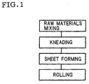
- Fig. 1 shows a flaw chart illustrating an example of a method of manufacturing a polarizable electrode according to the invention.
- Fig. 2 shows a schematic representation of a kneader used in the present invention.
- Fig. 3 shows a schematic representation of a roll-pressing machine used in the present invention.
- Fig. 4 shows a schematic representation of a rolling machine (reduction roller) used in the present invention.
- Fig. 5 shows a schematic diagram of electrical double layer capacitors in the examples 1 to 3 and a comparative example 1.
- the polarizable electrode of the present invention is a polarizable electrode for use in electrical double layer capacitors which comprises carbon fine-powders, a conductive auxiliary agent, and a binder, and which has tensile strength of not less than 0.13 MPa.
- the polarizable electrode when the polarizable electrode is impregnated with an electrolytic solution, the dropped carbon particles contained in the polarizable electrode can be suppressed, so that it is possible to reduce the long-term performance degradation and self-discharge caused energy losses of the electrical double layer capacitors.
- the dropped particle amount of the carbon particles leaving from the polarizable electrode into the electrolytic solution is preferably not more than 1.0 mg/cm 2 .
- the dropped particle amount of the carbon particles is more than 1.0 mg/cm 2 , the carbon particles suspended in the electrolytic solution become large in number, and therefore the self-discharge rate of the electrical double layer capacitor becomes high when it is in practical use, thereby resulting in the degradation of long-term performance of the electrical double layer capacitor.
- the polarizable electrode of the invention can make the self-discharge rate of the electrical double layer capacitor not more than 10%, the energy losses thereof can be reduced.
- the carbon fine-powder used in the invention can adsorb anions and cations existing in the electrolytic solution to form an electrical double layer, thus serving for storage of electrical power.
- the conductive auxiliary agent used in the invention increase the electrical conductivity between the carbon fine-powders themselves and between the carbon powders and the collector.
- the mixing ratio of the carbon fine-powder plays important role for increasing energy density per unit area in the polarizable electrode, and the mixing ratio of the conductive auxiliary agent exerts influence on the internal resistance of the polarizable electrode to contribute to improvement in the output density.
- the mixing ratio of the conductive auxiliary agent should be adjusted in accordance with the intended use of the polarizable electrode.
- the mixing ratio of the conductive auxiliary agent is 3 to 10 weight parts relative to 100 weight parts of carbon fine-powder.
- the mixing ratio of the conductive auxiliary agent is preferably 8 to 20 weight parts relative to 100 weight parts of carbon fine-powder.
- a mixture comprising a conductive auxiliary agent of 3 to 20 weight parts relative to 100 weight parts of carbon fine-powder is suitably used.
- the mixing ratio of the conductive auxiliary agent is more than 20 weight parts, the internal resistance can be little decreased and the mixing ratio of the carbon fine-powder contained in unit volume decreases conversely, thereby resulting in decreased energy density.
- the binder used in the invention is preferably a fluorine resin, and for example, the binder described in Japanese Patent Publication No. 7-44127 can be suitably used.
- polytetrafluoroethylene ethylene-tetorafluoroethylene copolymer, ethylene-chlorotrifluoroethylene, vinyliden fluoride copolymer, tetrafluoroethylene-perphloroalkylenevinylether copolymer etc.
- PTFE polytetrafluoroethylene
- ethylene-tetorafluoroethylene copolymer ethylene-chlorotrifluoroethylene
- vinyliden fluoride copolymer tetrafluoroethylene-perphloroalkylenevinylether copolymer etc.
- the tetorafluoroethylene can be suitably used because it is chemically stable.
- the mixing ratio of the above fluorine resin is preferably 3 to 15 weight parts (more preferably 5 to 10 weight parts) relative to 100 weight parts of carbon fine-powder.
- Fig. 1 is a flowchart illustrating one example of a method of manufacturing the polarizable electrode of the present invention.
- carbon powder prepared by adding a conductive auxiliary agent of the amount of 3 to 20 weight parts to 100 weight parts of a predetermined amount of carbon fine-powder, and a binder made of a fluorine resin are mixed together such that they may be uniformly dispersed (raw materials mixing process).
- the mixing is preferably performed at temperature not higher than the transition temperature of the fluorine resin (in the case of PTFE, at 19°C and below).
- the mixture obtained in the raw materials mixing process is sufficiently kneaded while heated at temperature between 20 and 120°C and subjected to shearing force, for example, by means of a kneader shown in Fig. 2 (kneading process).
- the fluorine resin of the binder has fine fiber-like structures, which are bound to each other so as to form kneaded material consisting of small piece clusters having small bulk density and apparent volume of about 0.01 to 10 cm 3 .
- the kneading temperature may be a temperature at which the fluorine resin exhibits enough flawability (for example, 50°C), and may be sufficient up to about 120°C.
- the applied shearing force and the time of kneading are adequate, provided that each of the materials can be sufficiently and uniformly kneaded with each other.
- liquid lubricant may be added in order to facilitate fibrous growth of the binder.
- the kneaded material obtained in the kneading process is formed into a sheet-like compact of a predetermined thickness (for example, 0.3 mm), for example, by means of a roll press machine (sheet forming process).
- the above sheet-like compact can be strengthened by partial binding between the finely fibrous structures which have been formed of the fluorine resin, by which carbon powder can be fixed more firmly.
- the sheet-like compact obtained in the sheet forming process can be used as a polarizable electrode even as it is.
- the sheet-like compact is rolled until a predetermined thickness (for example, 0.2 mm) is reached, for example, by means of a rolling machine (reduction roller) shown in Fig. 4, thereby polarizable-electrode sheets for use in capacitors being formed.
- this sheet is cut to a predetermined size, thereby intended polarizable electrodes for use in capacitors being obtained.
- the sheets for use in polarizable electrodes and the electrical double layer capacitors obtained in each example were evaluated in performance by the following methods.
- the polarizable-electrode sheets were stamped with a punch etc. into sheets of the shape of ⁇ 19 mm, which were dried sufficiently and then the initial weight W1 thereof was determined.
- this sheet was taken out of the acetonitrile and dried, and then the post-impregnation weight W2 was determined.
- Powdered activated-carbon 80%, carbonblack 10%, and polytetrafluoroethylene (PTFE) 10% were weighed, and sufficiently mixed together with water of the same weight as the solid matter, and then kneaded at 50°C for 10 minutes by means of a kneader. After that, the kneaded material was shaped through a roll forming machine into a polarizable electrode sheet of 150 ⁇ m thick.
- PTFE polytetrafluoroethylene
- a polarizable electrode 42 was brought into intimate contact with the surface of aluminum foil of a collecting electrode 40, and two sets of these were placed such that the polarizable electrodes 42 thereof could be opposed to each other. Then, a separator 44 made of cellulose was inserted between the polarizable electrodes 42, which then were impregnated with an electrolytic solution 48 that was a propylene carbonate solution of 1M boron 4-ethyl ammonium 4-fluoride, thereby forming a electrical double layer capacitor (refer to see Fig. 5).
- PTFE polytetrafluoroethylene
- Powdered activated-carbon 85%, carbonblack 10% and polytetrafluoroethylene (PTFE) 5% were weighed and sufficiently mixed together with water of the same weight as the solid matter, and then kneaded at 50°C for 20 minutes by means of a kneader. After that, the kneaded material was shaped through a roll forming machine into a sheet of 150 ⁇ m thick.
- PTFE polytetrafluoroethylene
- PTFE polytetrafluoroethylene
- the dropped particle amount of the carbon particles leaving into the electrolytic solution can be made not more than 1.0 mg/cm 2 and the self-discharge rate of the electrical double layer capacitors in practical can be made not higher than 10%, by making the tensile strength of the polarizable electrodes not less than 0.13 MPa.
- the polarizable electrode for use in electrical double layer capacitors allows reduction of long-term performance degradation and self-discharge caused energy losses of the electrical double layer capacitor, by suppressing the dropped the carbon powders contained in the polarizable electrode when it is impregnated with an electrolytic solution.
Abstract
Description
- The present invention relates to a polarizable electrode for use in electrical double layer capacitors.
- At present, uses of electrical double layer capacitors are being actively developed in various kinds of fields from the viewpoint of their sheet-like shape.
- In particular, significant reduction in the usage of fossil fuel by cars is required from the environmental and resource issues. As one of measures for such reduction, the spotlight is on so-called hybrid cars, which achieve the reduction in fossil fuel usage by the combination of fossil fuel and electricity. In this field, higher output density is demanded of a high output density type of electrical double layer capacitors.
- On the other hand, it is also increasing to use electrical double layer capacitors as so-called backup power sources in personal computers and various kinds of electrical machinery and apparatus. In this field, although a high energy density type of electrical double layer capacitors has been used, higher energy density is demanded of it.
- For these reasons, with regard to the polarizable electrodes for use in the electrical double layer capacitors, it is essential to increase the density of carbon fine-powder in the polarizable electrodes.
- However, in the polarizable electrodes currently used for electrical double layer capacitors, when the polarizable electrodes are impregnated with electrolytic solutions, the carbon particles contained in the polarizable electrodes easily drop out of there. Therefore, there has been a problem of degradation in the performance of the electrical double layer capacitors.
- Further, because the above polarizable electrodes have many particles suspended in the electrolytic solution, there have been a problem that energy losses in the electrical double layer capacitors become large due to high self-discharge therein.
- The present invention has been achieved in view of the fact that the conventional technologies have such problems, and thus has an object to provide a polarizable electrode for use in electrical double layer capacitors, which polarizable electrode can reduce the long-term performance degradation and self-discharge caused energy losses of the electrical double layer capacitors, by suppressing the dropped carbon particles when the polarizable electrode is impregnated with an electrolytic solution.
- That is, according to the present invention, there is provided a polarizable electrode for use in electrical double layer capacitors, which polarizable electrode comprises carbon fine-powder, a conductive auxiliary agent, and a binder, and which is characterized in that the tensile strength of the above described polarizable electrode is not less than 0.13 MPa.
- At this time, according to the invention, the dropped particle amount of the carbon particles leaving into the electrolytic solution is preferably not more than 1.0 mg/cm2.
- Fig. 1 shows a flaw chart illustrating an example of a method of manufacturing a polarizable electrode according to the invention.
- Fig. 2 shows a schematic representation of a kneader used in the present invention.
- Fig. 3 shows a schematic representation of a roll-pressing machine used in the present invention.
- Fig. 4 shows a schematic representation of a rolling machine (reduction roller) used in the present invention.
- Fig. 5 shows a schematic diagram of electrical double layer capacitors in the examples 1 to 3 and a comparative example 1.
- Hereinafter, the present invention will be described in detail.
- The polarizable electrode of the present invention is a polarizable electrode for use in electrical double layer capacitors which comprises carbon fine-powders, a conductive auxiliary agent, and a binder, and which has tensile strength of not less than 0.13 MPa.
- Thereby, when the polarizable electrode is impregnated with an electrolytic solution, the dropped carbon particles contained in the polarizable electrode can be suppressed, so that it is possible to reduce the long-term performance degradation and self-discharge caused energy losses of the electrical double layer capacitors.
- Then, in the polarizable electrode of the present invention, the dropped particle amount of the carbon particles leaving from the polarizable electrode into the electrolytic solution is preferably not more than 1.0 mg/cm2.
- That's because, if the dropped particle amount of the carbon particles is more than 1.0 mg/cm2, the carbon particles suspended in the electrolytic solution become large in number, and therefore the self-discharge rate of the electrical double layer capacitor becomes high when it is in practical use, thereby resulting in the degradation of long-term performance of the electrical double layer capacitor.
- Further, because the polarizable electrode of the invention can make the self-discharge rate of the electrical double layer capacitor not more than 10%, the energy losses thereof can be reduced.
- In addition, the carbon fine-powder used in the invention can adsorb anions and cations existing in the electrolytic solution to form an electrical double layer, thus serving for storage of electrical power.
- Further, the conductive auxiliary agent used in the invention increase the electrical conductivity between the carbon fine-powders themselves and between the carbon powders and the collector.
- Therefore, the mixing ratio of the carbon fine-powder plays important role for increasing energy density per unit area in the polarizable electrode, and the mixing ratio of the conductive auxiliary agent exerts influence on the internal resistance of the polarizable electrode to contribute to improvement in the output density.
- For this reason, the mixing ratio of the conductive auxiliary agent should be adjusted in accordance with the intended use of the polarizable electrode.
- For example, in the polarizable electrodes intended for use in applications of high energy density such as for the storage of electrical power, the mixing ratio of the conductive auxiliary agent is 3 to 10 weight parts relative to 100 weight parts of carbon fine-powder. In the polarizable electrodes intended for use in applications of high output density such as for electric cars, the mixing ratio of the conductive auxiliary agent is preferably 8 to 20 weight parts relative to 100 weight parts of carbon fine-powder.
- As the kneaded material used in the invention, a mixture comprising a conductive auxiliary agent of 3 to 20 weight parts relative to 100 weight parts of carbon fine-powder is suitably used.
- This is because, if the mixing ratio of the conductive auxiliary agent is less than 3 weight parts, the polarizable electrode has high internal resistance, thereby resulting in reduced output density.
- On the other hand, if the mixing ratio of the conductive auxiliary agent is more than 20 weight parts, the internal resistance can be little decreased and the mixing ratio of the carbon fine-powder contained in unit volume decreases conversely, thereby resulting in decreased energy density.
- The binder used in the invention is preferably a fluorine resin, and for example, the binder described in Japanese Patent Publication No. 7-44127 can be suitably used.
- That is, polytetrafluoroethylene(PTFE), ethylene-tetorafluoroethylene copolymer, ethylene-chlorotrifluoroethylene, vinyliden fluoride copolymer, tetrafluoroethylene-perphloroalkylenevinylether copolymer etc. can be named.
- In particular, the tetorafluoroethylene can be suitably used because it is chemically stable.
- Then, the mixing ratio of the above fluorine resin is preferably 3 to 15 weight parts (more preferably 5 to 10 weight parts) relative to 100 weight parts of carbon fine-powder.
- That's because, if the fluorine resin is less than 3 weight parts, it is impossible to obtain a sheet-like compact having tensile strength of not less than 0.13 MPa.
- On the other hand, that's also because, if the fluorine resin is more than 15 weight parts, not only the internal resistance increases, but also the ratio of the area occupied by carbon fine-powders per unit area decreases.
- Next, a method of manufacturing the polarizable electrode of the present invention will be described in detail based on the drawings.
- Fig. 1 is a flowchart illustrating one example of a method of manufacturing the polarizable electrode of the present invention.
- As shown in Fig. 1, first, carbon powder, prepared by adding a conductive auxiliary agent of the amount of 3 to 20 weight parts to 100 weight parts of a predetermined amount of carbon fine-powder, and a binder made of a fluorine resin are mixed together such that they may be uniformly dispersed (raw materials mixing process).
- Then, in order to suppress fibrous growing of the fluorine resin, the mixing is preferably performed at temperature not higher than the transition temperature of the fluorine resin (in the case of PTFE, at 19°C and below).
- The mixture obtained in the raw materials mixing process is sufficiently kneaded while heated at temperature between 20 and 120°C and subjected to shearing force, for example, by means of a kneader shown in Fig. 2 (kneading process).
- Thereby, the fluorine resin of the binder has fine fiber-like structures, which are bound to each other so as to form kneaded material consisting of small piece clusters having small bulk density and apparent volume of about 0.01 to 10 cm3.
- In addition, the kneading temperature may be a temperature at which the fluorine resin exhibits enough flawability (for example, 50°C), and may be sufficient up to about 120°C.
- Further, the applied shearing force and the time of kneading are adequate, provided that each of the materials can be sufficiently and uniformly kneaded with each other.
- Furthermore, in the kneading process, liquid lubricant may be added in order to facilitate fibrous growth of the binder.
- The kneaded material obtained in the kneading process is formed into a sheet-like compact of a predetermined thickness (for example, 0.3 mm), for example, by means of a roll press machine (sheet forming process).
- At this time, the above sheet-like compact can be strengthened by partial binding between the finely fibrous structures which have been formed of the fluorine resin, by which carbon powder can be fixed more firmly.
- The sheet-like compact obtained in the sheet forming process can be used as a polarizable electrode even as it is. However, when its thickness is to be controlled more accurately, and when more increased density is required, the sheet-like compact is rolled until a predetermined thickness (for example, 0.2 mm) is reached, for example, by means of a rolling machine (reduction roller) shown in Fig. 4, thereby polarizable-electrode sheets for use in capacitors being formed.
- Finally, this sheet is cut to a predetermined size, thereby intended polarizable electrodes for use in capacitors being obtained.
- Hereinafter, the present invention will be more specifically described based on examples, but the invention should not be limited to these examples.
- Further, the sheets for use in polarizable electrodes and the electrical double layer capacitors obtained in each example were evaluated in performance by the following methods.
- Tensile strength was measured in compliance with JIS K6301.
- The polarizable-electrode sheets were stamped with a punch etc. into sheets of the shape of 19 mm, which were dried sufficiently and then the initial weight W1 thereof was determined.
- Then, after dipped in acetonitrile, this sheet was taken out of the acetonitrile and dried, and then the post-impregnation weight W2 was determined.
- By substituting these values into the following equation, the dropped particle amount of the carbon particles was determined (per unit surface area of the sheet),
- The electrical double layer capacitor was charged at room temperature and at a constant voltage of 2.5 V for 12 hours. Thereafter, the circuit was opened and the electrical double layer capacitor was thus left at room temperature, and then the self-discharge rate was determined from the voltage variation after 72 hours by the following equation,
- Powdered activated-carbon 80%, carbonblack 10%, and polytetrafluoroethylene (PTFE) 10% were weighed, and sufficiently mixed together with water of the same weight as the solid matter, and then kneaded at 50°C for 10 minutes by means of a kneader. After that, the kneaded material was shaped through a roll forming machine into a polarizable electrode sheet of 150 µm thick.
- The tensile strength and the dropped particle amount of the carbon particles were respectively measured for this sheet. The results are shown in Table 1.
- The above obtained sheet, as a
polarizable electrode 42, was brought into intimate contact with the surface of aluminum foil of a collectingelectrode 40, and two sets of these were placed such that thepolarizable electrodes 42 thereof could be opposed to each other. Then, aseparator 44 made of cellulose was inserted between thepolarizable electrodes 42, which then were impregnated with anelectrolytic solution 48 that was a propylene carbonate solution of 1M boron 4-ethyl ammonium 4-fluoride, thereby forming a electrical double layer capacitor (refer to see Fig. 5). - Then, the self-discharge rate of the electrical double layer capacitor obtained was measured. The result is shown in Table 1.
- Powdered activated-carbon 80%, carbonblack 10% and polytetrafluoroethylene (PTFE) 10%, each of which was the same material as used in the example 1, were weighed and sufficiently mixed together with water of the same weight as the solid matter, and then kneaded at 50°C for 20 minutes by means of a kneader. After that, the kneaded material was shaped through a roll forming machine into a sheet of 150 µm thick.
- The tensile strength and the dropped particle amount of the carbon particles were respectively measured for this sheet. The results are shown in Table 1.
- An electrical double layer capacitor was made of the above obtained sheet in the same manner as in the example 1. Then, the self-discharge rate of the obtained electrical double layer capacitor was measured. The result is shown in Table 1.
- Powdered activated-carbon 85%, carbonblack 10% and polytetrafluoroethylene (PTFE) 5%, each of which was the same material as used in the example 1, were weighed and sufficiently mixed together with water of the same weight as the solid matter, and then kneaded at 50°C for 20 minutes by means of a kneader. After that, the kneaded material was shaped through a roll forming machine into a sheet of 150 µm thick.
- The tensile strength and the dropped particle amount of the carbon particles were respectively measured for this sheet. The results are shown in Table 1.
- An electrical double layer capacitor was made of the above obtained sheet in the same manner as in the example 1. Then, the self-discharge rate of the obtained electrical double layer capacitor was measured. The results is shown in Table 1.
- Powdered activated-carbon 80%, carbonblack 10% and polytetrafluoroethylene (PTFE) 10%, each of which was the same material as used in the example 1, were weighed and sufficiently mixed together with water of the same weight as the solid matter, and then kneaded at 50°C for 3 minutes by means of a pressure kneader. After that, the kneaded material was dried and ground, and then the ground material was shaped through a roll forming machine into a sheet of 150 µm thick.
- The tensile strength and the dropped particle amount of the carbon particles were respectively measured for this sheet. The results are shown in Table 1.
- An electrical double layer capacitor was made of the above obtained sheet in the same manner as in the example 1. Then, the self-discharge rate of the obtained electrical double layer capacitor was measured. The result is shown in Table 1.
Tensile strength Dropped particle amount Self-discharge rate Example 1 0.17 MPa 0.6 mg/cm2 8% Example 2 0.24 MPa 0.5 mg/cm2 6% Example 3 0.13 MPa 1.0 mg/cm2 9% Comparative example 1 0.11 MPa 1.3 mg/cm2 15% - From the results of Table 1, in the examples 1 to 3, the dropped particle amount of the carbon particles leaving into the electrolytic solution can be made not more than 1.0 mg/cm2 and the self-discharge rate of the electrical double layer capacitors in practical can be made not higher than 10%, by making the tensile strength of the polarizable electrodes not less than 0.13 MPa.
- As described above, the polarizable electrode for use in electrical double layer capacitors according to the present invention allows reduction of long-term performance degradation and self-discharge caused energy losses of the electrical double layer capacitor, by suppressing the dropped the carbon powders contained in the polarizable electrode when it is impregnated with an electrolytic solution.
Claims (2)
- A polarizable electrode for use in electrical double layer capacitors which comprises; carbon powder, a conductive auxiliary agent, and a binder,
characterized in that the tensile strength of said polarizable electrode is not less than 0.13 MPa. - The polarizable electrode for use in electrical double layer capacitors according to Claim 1,
wherein the dropped particle amount of the carbon particles leaving into the electrolytic solution is not more than 1.0 mg/cm2.
Applications Claiming Priority (3)
| Application Number | Priority Date | Filing Date | Title |
|---|---|---|---|
| JP2000080818 | 2000-03-22 | ||
| JP2000080818A JP2001267187A (en) | 2000-03-22 | 2000-03-22 | Polarizable electrode for electric double-layer capacitor |
| PCT/JP2001/002238 WO2001071739A1 (en) | 2000-03-22 | 2001-03-21 | Polarizable electrode for electric double-layer capacitor |
Publications (3)
| Publication Number | Publication Date |
|---|---|
| EP1187153A1 true EP1187153A1 (en) | 2002-03-13 |
| EP1187153A4 EP1187153A4 (en) | 2005-08-03 |
| EP1187153B1 EP1187153B1 (en) | 2007-09-19 |
Family
ID=18597862
Family Applications (1)
| Application Number | Title | Priority Date | Filing Date |
|---|---|---|---|
| EP01917482A Expired - Lifetime EP1187153B1 (en) | 2000-03-22 | 2001-03-21 | Polarizable electrode for electric double-layer capacitor |
Country Status (5)
| Country | Link |
|---|---|
| US (1) | US6614646B2 (en) |
| EP (1) | EP1187153B1 (en) |
| JP (1) | JP2001267187A (en) |
| DE (1) | DE60130528T2 (en) |
| WO (1) | WO2001071739A1 (en) |
Families Citing this family (42)
| Publication number | Priority date | Publication date | Assignee | Title |
|---|---|---|---|---|
| JP2004193571A (en) * | 2002-11-29 | 2004-07-08 | Honda Motor Co Ltd | Polarized electrodes for electric double layer capacitor, manufacturing method of polarized electrodes for electric double layer capacitor, and manufacturing method of electric double layer capacitor |
| JP2004186273A (en) | 2002-11-29 | 2004-07-02 | Honda Motor Co Ltd | Electrode sheet for electric double layer capacitor, its manufacturing method, polarizable electrode, and electric double layer capacitor using the same |
| US6831826B2 (en) | 2002-11-29 | 2004-12-14 | Honda Motor Co., Ltd. | Polarized electrode for electric double-layer condenser, and electric double-layer condenser manufactured using the same, and process for manufacturing electrode sheet for electric double-layer condenser, and laminating apparatus |
| US7160615B2 (en) | 2002-11-29 | 2007-01-09 | Honda Motor Co., Ltd. | Granules for formation of an electrode of an electric double layer capacitor, manufacturing method thereof, electrode sheet, polarized electrode, and electric double layer capacitor using a polarized electrode |
| US20070122698A1 (en) | 2004-04-02 | 2007-05-31 | Maxwell Technologies, Inc. | Dry-particle based adhesive and dry film and methods of making same |
| US20050266298A1 (en) * | 2003-07-09 | 2005-12-01 | Maxwell Technologies, Inc. | Dry particle based electro-chemical device and methods of making same |
| US20050250011A1 (en) * | 2004-04-02 | 2005-11-10 | Maxwell Technologies, Inc. | Particle packaging systems and methods |
| US7352558B2 (en) | 2003-07-09 | 2008-04-01 | Maxwell Technologies, Inc. | Dry particle based capacitor and methods of making same |
| US7791860B2 (en) * | 2003-07-09 | 2010-09-07 | Maxwell Technologies, Inc. | Particle based electrodes and methods of making same |
| US20100014215A1 (en) * | 2004-04-02 | 2010-01-21 | Maxwell Technologies, Inc. | Recyclable dry particle based electrode and methods of making same |
| US20060147712A1 (en) * | 2003-07-09 | 2006-07-06 | Maxwell Technologies, Inc. | Dry particle based adhesive electrode and methods of making same |
| US7342770B2 (en) * | 2003-07-09 | 2008-03-11 | Maxwell Technologies, Inc. | Recyclable dry particle based adhesive electrode and methods of making same |
| US7295423B1 (en) * | 2003-07-09 | 2007-11-13 | Maxwell Technologies, Inc. | Dry particle based adhesive electrode and methods of making same |
| US20110165318A9 (en) * | 2004-04-02 | 2011-07-07 | Maxwell Technologies, Inc. | Electrode formation by lamination of particles onto a current collector |
| US7508651B2 (en) * | 2003-07-09 | 2009-03-24 | Maxwell Technologies, Inc. | Dry particle based adhesive and dry film and methods of making same |
| US7920371B2 (en) | 2003-09-12 | 2011-04-05 | Maxwell Technologies, Inc. | Electrical energy storage devices with separator between electrodes and methods for fabricating the devices |
| US7495349B2 (en) | 2003-10-20 | 2009-02-24 | Maxwell Technologies, Inc. | Self aligning electrode |
| US7384433B2 (en) * | 2004-02-19 | 2008-06-10 | Maxwell Technologies, Inc. | Densification of compressible layers during electrode lamination |
| US7090946B2 (en) | 2004-02-19 | 2006-08-15 | Maxwell Technologies, Inc. | Composite electrode and method for fabricating same |
| US7492571B2 (en) * | 2004-04-02 | 2009-02-17 | Linda Zhong | Particles based electrodes and methods of making same |
| US20060137158A1 (en) * | 2004-04-02 | 2006-06-29 | Maxwell Technologies, Inc. | Dry-particle packaging systems and methods of making same |
| US7227737B2 (en) | 2004-04-02 | 2007-06-05 | Maxwell Technologies, Inc. | Electrode design |
| US20060246343A1 (en) * | 2004-04-02 | 2006-11-02 | Maxwell Technologies, Inc. | Dry particle packaging systems and methods of making same |
| US7245478B2 (en) | 2004-08-16 | 2007-07-17 | Maxwell Technologies, Inc. | Enhanced breakdown voltage electrode |
| US7440258B2 (en) | 2005-03-14 | 2008-10-21 | Maxwell Technologies, Inc. | Thermal interconnects for coupling energy storage devices |
| CA2612639C (en) * | 2005-06-24 | 2014-08-26 | Samvel Avakovich Kazaryan | Current collector for double electric layer electrochemical capacitors and method of manufacture thereof |
| CA2612642A1 (en) * | 2005-06-24 | 2007-01-04 | Valery Pavlovich Nedoshivin | Electrode and current collector for electrochemical capacitor having double electric layer and double electric layer electrochemical capacitor formed therewith |
| EP1897104A1 (en) * | 2005-06-24 | 2008-03-12 | Universal Supercapacitors Llc. | Heterogeneous electrochemical supercapacitor and method of manufacture |
| WO2007139008A1 (en) * | 2006-05-29 | 2007-12-06 | Panasonic Corporation | Electric double layer capacitor and method for manufacturing the same |
| CN101490773B (en) * | 2006-07-14 | 2011-12-21 | 松下电器产业株式会社 | Electric double layer capacitor and method for manufacturing same |
| US8518573B2 (en) | 2006-09-29 | 2013-08-27 | Maxwell Technologies, Inc. | Low-inductive impedance, thermally decoupled, radii-modulated electrode core |
| AU2007325245A1 (en) | 2006-11-27 | 2008-06-05 | Universal Supercapacitors Llc | Electrode for use with double electric layer electrochemical capacitors having high specific parameters |
| US20080201925A1 (en) | 2007-02-28 | 2008-08-28 | Maxwell Technologies, Inc. | Ultracapacitor electrode with controlled sulfur content |
| US7649730B2 (en) | 2007-03-20 | 2010-01-19 | Avx Corporation | Wet electrolytic capacitor containing a plurality of thin powder-formed anodes |
| JP2008270349A (en) * | 2007-04-17 | 2008-11-06 | Mitsubishi Electric Corp | Electrode for electric double-layer capacitor and method for manufacturing same |
| US7903390B2 (en) * | 2008-06-19 | 2011-03-08 | Gas Technology Institute | Bipolar membrane for electrochemical supercapacitors and other capacitors |
| US20100008020A1 (en) * | 2008-07-09 | 2010-01-14 | Adrian Schneuwly | Electrode device |
| US8223473B2 (en) | 2009-03-23 | 2012-07-17 | Avx Corporation | Electrolytic capacitor containing a liquid electrolyte |
| US20110204284A1 (en) * | 2010-02-25 | 2011-08-25 | Renee Kelly Duncan | Carbon electrode batch materials and methods of using the same |
| WO2012112481A1 (en) * | 2011-02-16 | 2012-08-23 | Drexel University | Electrochemical flow capacitors |
| US9478364B2 (en) * | 2013-08-22 | 2016-10-25 | Corning Incorporated | Carbon-based electrodes containing molecular sieve |
| EP3459094B1 (en) | 2016-05-20 | 2022-08-17 | KYOCERA AVX Components Corporation | Ultracapacitor for use at high temperatures |
Citations (4)
| Publication number | Priority date | Publication date | Assignee | Title |
|---|---|---|---|---|
| US4862328A (en) * | 1985-08-13 | 1989-08-29 | Asahi Glass Company Ltd. | Electric double layer capacitor |
| EP0712143A2 (en) * | 1994-11-02 | 1996-05-15 | Japan Gore-Tex, Inc. | An electric double-layer capacitor and method for manufacture of an electrode therefor |
| DE19859990A1 (en) * | 1997-12-24 | 1999-07-01 | Asahi Glass Co Ltd | Production of electrodes for double-layer condensers |
| EP0933791A1 (en) * | 1998-01-30 | 1999-08-04 | Asahi Glass Company Ltd. | Electrode for an electric double layer capacitor and process for producing it |
Family Cites Families (8)
| Publication number | Priority date | Publication date | Assignee | Title |
|---|---|---|---|---|
| JP3028560B2 (en) | 1990-07-09 | 2000-04-04 | 松下電器産業株式会社 | Method for manufacturing polarizable electrode of electric double layer capacitor |
| JP3266373B2 (en) | 1993-08-02 | 2002-03-18 | 富士通株式会社 | Plasma display panel |
| JP3791180B2 (en) | 1998-04-23 | 2006-06-28 | 旭硝子株式会社 | Electrode for electric double layer capacitor and electric double layer capacitor having the electrode |
| JP4026226B2 (en) | 1998-04-23 | 2007-12-26 | 旭硝子株式会社 | Electrode for electric double layer capacitor and electric double layer capacitor having the electrode |
| JP2000036433A (en) | 1998-05-12 | 2000-02-02 | Mitsubishi Rayon Co Ltd | Electric double-layer capacitor and manufacture thereof |
| JP2000049055A (en) | 1998-07-27 | 2000-02-18 | Asahi Glass Co Ltd | Electric double layer capacitor and electrode for it |
| JP2000200737A (en) | 1998-11-05 | 2000-07-18 | Ngk Insulators Ltd | Polarizable electrode for electric double layer capacitor and manufacture thereof |
| JP4266420B2 (en) | 1998-12-10 | 2009-05-20 | クレハエラストマー株式会社 | Carbon sheet and manufacturing method thereof |
-
2000
- 2000-03-22 JP JP2000080818A patent/JP2001267187A/en active Pending
-
2001
- 2001-03-21 US US10/009,665 patent/US6614646B2/en not_active Expired - Fee Related
- 2001-03-21 DE DE60130528T patent/DE60130528T2/en not_active Expired - Lifetime
- 2001-03-21 EP EP01917482A patent/EP1187153B1/en not_active Expired - Lifetime
- 2001-03-21 WO PCT/JP2001/002238 patent/WO2001071739A1/en active IP Right Grant
Patent Citations (4)
| Publication number | Priority date | Publication date | Assignee | Title |
|---|---|---|---|---|
| US4862328A (en) * | 1985-08-13 | 1989-08-29 | Asahi Glass Company Ltd. | Electric double layer capacitor |
| EP0712143A2 (en) * | 1994-11-02 | 1996-05-15 | Japan Gore-Tex, Inc. | An electric double-layer capacitor and method for manufacture of an electrode therefor |
| DE19859990A1 (en) * | 1997-12-24 | 1999-07-01 | Asahi Glass Co Ltd | Production of electrodes for double-layer condensers |
| EP0933791A1 (en) * | 1998-01-30 | 1999-08-04 | Asahi Glass Company Ltd. | Electrode for an electric double layer capacitor and process for producing it |
Non-Patent Citations (1)
| Title |
|---|
| See also references of WO0171739A1 * |
Also Published As
| Publication number | Publication date |
|---|---|
| JP2001267187A (en) | 2001-09-28 |
| WO2001071739A1 (en) | 2001-09-27 |
| DE60130528D1 (en) | 2007-10-31 |
| US6614646B2 (en) | 2003-09-02 |
| DE60130528T2 (en) | 2008-06-12 |
| EP1187153A4 (en) | 2005-08-03 |
| EP1187153B1 (en) | 2007-09-19 |
| US20020181186A1 (en) | 2002-12-05 |
Similar Documents
| Publication | Publication Date | Title |
|---|---|---|
| EP1187153A1 (en) | Polarizable electrode for electric double-layer capacitor | |
| US11587741B2 (en) | Compositions and methods for energy storage device electrodes | |
| EP2082407B1 (en) | Electrode for energy storage device | |
| US7811337B2 (en) | Ultracapacitor electrode with controlled sulfur content | |
| US7245478B2 (en) | Enhanced breakdown voltage electrode | |
| US20080204973A1 (en) | Ultracapacitor electrode with controlled iron content | |
| US20070146967A1 (en) | Ultracapacitor electrode with controlled carbon content | |
| US20040170821A1 (en) | Granules for formation of an electrode of an electric double layer capacitor, manufacturing mehtod thereof, electrode sheet, polarized electrode, and electric double layer capacitor using a polarized electrode | |
| EP2088604B1 (en) | Electrode membrane, electrode and method for producing the same, and electric double layer capacitor | |
| WO2009123031A1 (en) | Method for producing electrode for electrochemical device | |
| JP2002260970A (en) | Activated carbonaceous structure and electric double- layer capacitor using the same | |
| JP2004186275A (en) | Electrode sheet for electric double layer capacitor, its manufacturing method, polarizable electrode, and electric double layer capacitor using the same | |
| KR20110135096A (en) | An electrode for electric double layer capacitor and method of manufacturing an electrode | |
| US20230207226A1 (en) | Compositions and methods for energy storage device electrodes |
Legal Events
| Date | Code | Title | Description |
|---|---|---|---|
| PUAI | Public reference made under article 153(3) epc to a published international application that has entered the european phase |
Free format text: ORIGINAL CODE: 0009012 |
|
| AK | Designated contracting states |
Kind code of ref document: A1 Designated state(s): AT BE CH CY DE DK ES FI FR GB GR IE IT LI LU MC NL PT SE TR |
|
| 17P | Request for examination filed |
Effective date: 20020313 |
|
| RBV | Designated contracting states (corrected) |
Designated state(s): DE FR GB |
|
| A4 | Supplementary search report drawn up and despatched |
Effective date: 20050620 |
|
| RIC1 | Information provided on ipc code assigned before grant |
Ipc: 7H 01G 9/058 A Ipc: 7H 01G 9/00 B |
|
| 17Q | First examination report despatched |
Effective date: 20060307 |
|
| GRAP | Despatch of communication of intention to grant a patent |
Free format text: ORIGINAL CODE: EPIDOSNIGR1 |
|
| RIN1 | Information on inventor provided before grant (corrected) |
Inventor name: NAKAGAWA, TOSHIHIKO Inventor name: ONO, MASASHI Inventor name: BOGAKI, TOMOHIRO |
|
| GRAS | Grant fee paid |
Free format text: ORIGINAL CODE: EPIDOSNIGR3 |
|
| GRAA | (expected) grant |
Free format text: ORIGINAL CODE: 0009210 |
|
| AK | Designated contracting states |
Kind code of ref document: B1 Designated state(s): DE FR GB |
|
| REG | Reference to a national code |
Ref country code: GB Ref legal event code: FG4D |
|
| REF | Corresponds to: |
Ref document number: 60130528 Country of ref document: DE Date of ref document: 20071031 Kind code of ref document: P |
|
| EN | Fr: translation not filed | ||
| PLBE | No opposition filed within time limit |
Free format text: ORIGINAL CODE: 0009261 |
|
| STAA | Information on the status of an ep patent application or granted ep patent |
Free format text: STATUS: NO OPPOSITION FILED WITHIN TIME LIMIT |
|
| 26N | No opposition filed |
Effective date: 20080620 |
|
| PG25 | Lapsed in a contracting state [announced via postgrant information from national office to epo] |
Ref country code: FR Free format text: LAPSE BECAUSE OF FAILURE TO SUBMIT A TRANSLATION OF THE DESCRIPTION OR TO PAY THE FEE WITHIN THE PRESCRIBED TIME-LIMIT Effective date: 20080523 |
|
| GBPC | Gb: european patent ceased through non-payment of renewal fee |
Effective date: 20080321 |
|
| PG25 | Lapsed in a contracting state [announced via postgrant information from national office to epo] |
Ref country code: GB Free format text: LAPSE BECAUSE OF NON-PAYMENT OF DUE FEES Effective date: 20080321 |
|
| PGFP | Annual fee paid to national office [announced via postgrant information from national office to epo] |
Ref country code: DE Payment date: 20140417 Year of fee payment: 14 |
|
| REG | Reference to a national code |
Ref country code: DE Ref legal event code: R119 Ref document number: 60130528 Country of ref document: DE |
|
| PG25 | Lapsed in a contracting state [announced via postgrant information from national office to epo] |
Ref country code: DE Free format text: LAPSE BECAUSE OF NON-PAYMENT OF DUE FEES Effective date: 20151001 |