EP1186927A2 - Verstellvorrichtung und Verfahren zu ihrer Justierung - Google Patents
Verstellvorrichtung und Verfahren zu ihrer Justierung Download PDFInfo
- Publication number
- EP1186927A2 EP1186927A2 EP01118126A EP01118126A EP1186927A2 EP 1186927 A2 EP1186927 A2 EP 1186927A2 EP 01118126 A EP01118126 A EP 01118126A EP 01118126 A EP01118126 A EP 01118126A EP 1186927 A2 EP1186927 A2 EP 1186927A2
- Authority
- EP
- European Patent Office
- Prior art keywords
- adjustment
- adjusting device
- elements
- carrier plate
- base plate
- Prior art date
- Legal status (The legal status is an assumption and is not a legal conclusion. Google has not performed a legal analysis and makes no representation as to the accuracy of the status listed.)
- Granted
Links
- 238000000034 method Methods 0.000 title claims description 23
- 230000005693 optoelectronics Effects 0.000 claims abstract description 16
- 230000005855 radiation Effects 0.000 claims abstract description 13
- 230000008569 process Effects 0.000 claims description 12
- 239000013307 optical fiber Substances 0.000 claims description 9
- 239000000463 material Substances 0.000 claims description 5
- 230000005540 biological transmission Effects 0.000 claims description 3
- 206010073306 Exposure to radiation Diseases 0.000 abstract 1
- 238000005452 bending Methods 0.000 description 12
- 239000007787 solid Substances 0.000 description 8
- 239000002184 metal Substances 0.000 description 7
- 230000008859 change Effects 0.000 description 5
- 239000003365 glass fiber Substances 0.000 description 5
- 239000004065 semiconductor Substances 0.000 description 5
- 238000013461 design Methods 0.000 description 4
- 239000000835 fiber Substances 0.000 description 4
- 230000008878 coupling Effects 0.000 description 3
- 238000010168 coupling process Methods 0.000 description 3
- 238000005859 coupling reaction Methods 0.000 description 3
- 230000007774 longterm Effects 0.000 description 3
- 230000003287 optical effect Effects 0.000 description 3
- 238000012545 processing Methods 0.000 description 3
- 238000007493 shaping process Methods 0.000 description 3
- 238000003466 welding Methods 0.000 description 3
- 230000008901 benefit Effects 0.000 description 2
- 238000005520 cutting process Methods 0.000 description 2
- 238000010438 heat treatment Methods 0.000 description 2
- 238000004904 shortening Methods 0.000 description 2
- 238000005476 soldering Methods 0.000 description 2
- 238000000137 annealing Methods 0.000 description 1
- 238000013459 approach Methods 0.000 description 1
- 230000009286 beneficial effect Effects 0.000 description 1
- 239000000969 carrier Substances 0.000 description 1
- 238000004891 communication Methods 0.000 description 1
- 238000001816 cooling Methods 0.000 description 1
- 238000005530 etching Methods 0.000 description 1
- 230000035876 healing Effects 0.000 description 1
- 230000003993 interaction Effects 0.000 description 1
- 238000003698 laser cutting Methods 0.000 description 1
- 230000007246 mechanism Effects 0.000 description 1
- 238000002844 melting Methods 0.000 description 1
- 230000008018 melting Effects 0.000 description 1
- 238000003825 pressing Methods 0.000 description 1
- 238000004080 punching Methods 0.000 description 1
- 230000000087 stabilizing effect Effects 0.000 description 1
- 230000003068 static effect Effects 0.000 description 1
- 239000003351 stiffener Substances 0.000 description 1
- 238000013519 translation Methods 0.000 description 1
- 230000001960 triggered effect Effects 0.000 description 1
- XLYOFNOQVPJJNP-UHFFFAOYSA-N water Substances O XLYOFNOQVPJJNP-UHFFFAOYSA-N 0.000 description 1
Images



Classifications
-
- G—PHYSICS
- G02—OPTICS
- G02B—OPTICAL ELEMENTS, SYSTEMS OR APPARATUS
- G02B6/00—Light guides; Structural details of arrangements comprising light guides and other optical elements, e.g. couplings
- G02B6/24—Coupling light guides
- G02B6/42—Coupling light guides with opto-electronic elements
- G02B6/4201—Packages, e.g. shape, construction, internal or external details
- G02B6/4219—Mechanical fixtures for holding or positioning the elements relative to each other in the couplings; Alignment methods for the elements, e.g. measuring or observing methods especially used therefor
- G02B6/422—Active alignment, i.e. moving the elements in response to the detected degree of coupling or position of the elements
- G02B6/4226—Positioning means for moving the elements into alignment, e.g. alignment screws, deformation of the mount
-
- G—PHYSICS
- G02—OPTICS
- G02B—OPTICAL ELEMENTS, SYSTEMS OR APPARATUS
- G02B7/00—Mountings, adjusting means, or light-tight connections, for optical elements
- G02B7/02—Mountings, adjusting means, or light-tight connections, for optical elements for lenses
- G02B7/023—Mountings, adjusting means, or light-tight connections, for optical elements for lenses permitting adjustment
Definitions
- the laser module used is the divergent laser beam a laser diode using one or more lenses mapped onto the end face of an optical fiber in this way, that the highest possible coupling efficiency of the laser power is achieved in the optical fiber.
- This is achieved in that a single lens or a pair of lenses the so-called spot size of the laser onto the light entry opening of the glass fiber is mapped.
- first lens preferably uses an aspherical lens.
- the two-lens arrangements are also often collimated Beam aimed between the two lenses because then the distance between the lenses is not critical. However, it is with two-lens arrangements it is also possible that the first Lens produces a greatly enlarged intermediate image that of the second lens back onto the light entry opening Fiber is reduced.
- Semiconductor laser for long-range optical transmission systems emit at wavelengths of 1.3 ⁇ m or 1.55 ⁇ m and have spot radii of the order of 1 ⁇ m.
- Corresponding monomode glass fibers have spot radii in one Order of 5 ⁇ m.
- the first lens must typically achieve with accuracy from ⁇ 0.5 ⁇ m in the x and y direction and from ⁇ 2 to 5 ⁇ m adjusted and fixed in the z direction with respect to the laser chip become.
- the fixation usually either by means of AuSn soldering or by means of Laser welding performed. So that the lens wearer with reasonable Tolerances can be established or a Welding distortion when fixing the lens holder can be corrected , it is particularly advantageous if a targeted Readjustment of the lens holder and thus the lens position can be carried out by means of laser pulses.
- the optical fiber can also be connected directly to the laser be coupled. The fiber end face is often used for this melted or etched so that a suitable lens profile is created on the glass fiber itself. In this case the (locally metallized) glass fiber e.g. by soldering on attached to the laser-adjustable carrier.
- EP 0 373 225 A1 describes an optoelectronic semiconductor device described in which an optoelectronic Semiconductor component is held by a carrier block and attached to the support block at the same time a lens holder is in one opposite the optoelectronic component positioned lens is mounted.
- the lens holder is like this preformed that by local exposure to a Laser beam deformed in a desired way and thus the Position of the lens in relation to the optoelectronic component can be changed.
- US 5,572,895 describes a mutual method Adjustment of two links connected by a bridge described one or more actuators. Also at This procedure will place the actuators in suitable locations Laser energy supplied to bring about a desired adjustment.
- US 6,030,114 discloses a laser adjustable Fuse switch, which works on the same principle as shown above a pre-bent contact connection of a Bimetal strip for calibration purposes under application can be adjusted with a laser beam.
- Actuators that are operated by local Radiant energy, preferably in the form of laser radiation, are changeable in shape, at one end with a stationary base plate and at its other end with a movable support plate connected. Can on the carrier plate mounted an optical component to be adjusted like a lens become.
- the adjustment device can also be part an optoelectronic transceiver, which is an optoelectronic component such as a laser diode or a semiconductor photodetector and a connection opening for an optical fiber and in which the optoelectronic Component-holding carrier on stationary Parts of the adjustment device is mounted, being in the assembled and adjusted state the optoelectronic component with the lens and the light entry opening of the optical fiber is exactly aligned.
- an optoelectronic transceiver is an optoelectronic component such as a laser diode or a semiconductor photodetector and a connection opening for an optical fiber and in which the optoelectronic Component-holding carrier on stationary Parts of the adjustment device is mounted, being in the assembled and adjusted state the optoelectronic component with the lens and the light entry opening of the optical fiber is exactly aligned.
- the invention creates the possibility between base plate and carrier plate a plurality of actuators different Arrange type with which the different degrees of freedom independent of the adjustment and movement of the carrier plate are adjustable from each other.
- the Invention the possibility of several control elements in such a relative manner to arrange to each other with different Translation act, so that an actuator for rough adjustment and the second can be used for fine adjustment.
- the individual control elements can be different, in part have designs known per se in the prior art.
- On Adjustment element can, for example, in a particularly simple Design as a linear, especially rod-shaped control element be formed, which by applying a laser beam or the like along a direction in its length is changeable. It can be provided that the control element in its entire length by a thin Rod is formed, which is used to change the length at every point Radiant energy can be applied. Since this is in the Is usually not particularly stable, you usually choose embodiments, where those between more stable sections are larger Diameter (actuator elements) weak points Diameter (webs) are formed on which the radiation energy should be coupled and on which the actual Length change takes place.
- one can only unidirectional actuator a number of two or have more actuator elements, which in the direction of Normals between the base plate and the support plate with spaced from each other and each by at least a web running in the normal direction with each other are connected.
- Several bridges can also be used in parallel be arranged. These webs can be so close together be that the application of only individual of them only to a change in length in the normal direction leads. However, the webs can also be spaced further apart be so that a radiation exposure to a individual web-induced change in length a movement the carrier plate with a component in the normal direction and a component transversely to the normal direction.
- a Actuator a number of three or more actuator elements has that between the base plate and the support plate are arranged, with at least two control elements are so arranged relative to each other that they are in Direction of the normal between the base plate and the carrier plate spaced apart and through at least one web are connected to each other and at least two other actuators so relative to each other are arranged to be in a lateral direction from each other spaced apart and by at least one web are connected.
- An essential aspect of the invention mentioned above is that it opens up the possibility of an adjustment device to construct at for a degree of freedom first a rough adjustment and then for the same Degree of freedom a fine adjustment can be carried out.
- a first actuator with the support plate at a distance a from an outer edge of the carrier plate connected and at a distance b therefrom is a second Adjusting element connected to the support plate, so that with the first adjustment a rough adjustment and with the second Adjustment a fine adjustment with the gear ratio a / (a + b) is feasible.
- Another equally simple control element is a two-dimensional, in particular plate-shaped element, which by applying it appropriately its shape in two Directions can change.
- actuators there are other more complex types of actuators imaginable, which between the base plate and the support plate can be assembled.
- an off of EP 0 373 225 already mentioned, essentially known Control element can be used, which two at an angle plane arranged to each other and connected by a joint Has sections.
- Such an actuator can like that other described actuators formed from a sheet metal part his.
- the joint at the kink between the two flat sections can easily be reduced by a Sheet thickness and / or through recesses in the sheet metal part be educated.
- a complete adjustment device can two or more such angular adjusting elements are formed be on two opposite sides of the support plate are arranged, preferably the kinks the angular actuators facing each other are.
- Such an adjustment device has the advantage that with it depending on the locations of the controls where the Radiant energy is supplied, adjustment processes in different opposite directions performed can be.
- adjustment processes in different opposite directions performed can be.
- such angular ones Control elements directly with the base plate and the Carrier plate to be connected, at the junctions Joints can be provided in a simple manner reduced sheet thickness and / or through recesses in the Sheet metal part are formed.
- an actuator with an angular element is connected, which two at an angle arranged to each other and connected by a joint has flat and rigid sections, the angular element with its flat sections with the base plate and the carrier plate is connected and at least one of these Connections has a joint, which preferably also is shaped as described above.
- the angular actuator acts as a design during the adjustment process indirectly on the carrier plate by first the flat sections of the angle element on each other moved towards or away from each other.
- An important application of the adjustment device according to the invention relates to the adjustment of a mounted on the carrier plate Lens relative to an optoelectronic component such as a semiconductor laser and a light entry or exit surface an optical fiber.
- the adjustment device can thus be part of an optoelectronic transceiver be a transmit / receive component, a connection opening for an optical fiber and one between the connection opening and the transmission / reception component arranged lens, the lens on a carrier plate of an adjusting device according to the invention is mounted.
- the transmit / receive component and / or the fiber connection opening can on fixed parts the adjustment device as the base plate.
- the different arrangements of adjustment devices allow a defined and reproducible adjustment, so that with large quantities also an automation of the adjustment process is possible.
- the necessary (lens) carriers can be inexpensively, for example, using conventional stamping and bending processes are produced.
- Fig. 1 is an embodiment of an inventive Adjustment device shown schematically, in which a Adjustment of a lens 1 mounted on a carrier plate 2 should be made possible.
- the lens 1 is on one end of the rigid and torsionally rigid Carrier plate 2 mounted and this is generally in two Levels E1 and E2 with the also resistant to bending and torsion Base plate 3 connected.
- the plane is E1 through points A, B, F, E and plane E2 through the points C, G, H, D defined.
- the laser chip (not shown) is also firmly connected to this base plate 3.
- the fasteners in the levels E1 and E2 should be trained in this way be that the lens 1 with respect to the base plate 3 in x and y direction is adjustable. For adjustment in the x and y direction are expediently in levels E1 or E2 or in two levels of adjusting elements or actuators.
- actuators "At" which is a rough and fine adjustment of the lens position in the x and y direction as well as an adjustment in the z direction.
- the "rough adjustment” has an adjustment range of 1 to 50 ⁇ m and the fine adjustment cover a range from 0.1 to 5 ⁇ m. Because the adjustment tolerance in the z direction for the selected one Application is typically an order of magnitude larger than in x and y direction, a "rough adjustment" in the z direction is sufficient out.
- flex elements flexible two-dimensional connecting elements, hereinafter referred to as "flex elements".
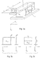
- Fig. 3a shows an example of such a structure, it being initially assumed that the lens 1 should only be adjusted in the x and y directions.
- the structure contains two flex elements Fl 1 and Fl 2 , which have a high rigidity in the x and y planes and one or two flex elements Fl 3 orthogonal to them and - possibly symmetrically arranged with respect to the yz plane Fl 4 (Fl 4 is not shown for the sake of clarity), which have high rigidity in the y and z planes.
- FIG. 3b shows how the flex elements Fl 1 and Fl 2 are warped in the plane by laser bombardment and thus can perform the desired movement of the lens 1 in the x and y directions. Suitable configurations of such flex elements will be shown later.
- the flexible joints G in the flexible elements Fl 3 and Fl 4 (see FIG. 3c) enable this movement while simultaneously stabilizing the z position.
- the joints G are solid-state joints with a small cross-section (reduced width, possibly additionally reduced thickness).
- Fig. 4a, b shows an embodiment similar to Fig. 2a with linear Actuators
- the necessary stiffness in the y and z-plane through the angular connecting element (flex element) F1 is reached.
- To increase the bending and torsional stiffness of the flex elements can do this by appropriate Shaping (pressing or bending of suitable profiles) be stiffened.
- the mobility in the x / y direction is achieved by means of flexible solid joints to a Stiffening in the x and y direction using the drawn Enable actuators.
- the actuators are according to the invention also executed as solid-state elements by laser bombardment can be deliberately deformed. By laser bombardment will either bend or shrink the Solid-state element reached, the desired movement of the Actuator.
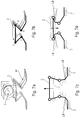
- FIG. 5a, b and 6 show examples of actuators in which one Bending is used by laser bombardment. Depending on the position The laser bombardment can increase the kink angle of the actuator or be reduced.
- Such actuators are, for example in EP-0 373 225.
- Fig.5a, b show an actuator, which at the ends of its flat sections with an angular connecting element (flex element) F1 is connected, which in turn with the support plate 2 and the base plate 3 is connected.
- FIGS. 7a, b For spatial adjustment with the laser beam on one side
- the adjustment device shown in FIGS. 7a, b became accessible designed.
- This adjustment device exists from a carrier plate 2 for the lens 2 or the lens frame as well as for reasons of static certainty from 3 Actuator legs in the form of angular control elements. It but 2, 4 or more actuator legs are also conceivable. In the middle and the legs have slits at the top, which is the bending stiffness of the material at these points weaknesses. As a result, these areas of the actuator act like joints during laser beam bending processing. For one Upward movement, the legs are simultaneous at the lower end loaded with a laser beam LB, see Fig. 7c.
- a disadvantage of the actuators based on bending is that according to mechanical tension built into the actuator after laser bombardment that are particularly important when the temperature changes over long periods of time Shape changes can result. A healing the built-in stresses caused by annealing is generally not possible, otherwise the deformation achieved is partially lost again goes. For particularly long-term stable structures are therefore Actuators beneficial to shrink processes by laser bombardment based. Here it is generally also possible after Laser adjustment of the built-in voltages through a largely reduce local heat treatment again without the Undo deformation.
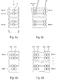
- FIG. 8a, b show examples of linear actuators (for a degree of freedom of adjustment) due to shrinkage based on laser bombardment.
- the suitable positions for the Laser bombardment is marked with "S".
- S The suitable positions for the Laser bombardment
- FIG. 8c, d show actuators making an adjustment in two degrees of freedom allow. For example, the positions S1 and S2 bombarded in pairs, then shortened in the y direction. However, if only positions S1 or S2 are shot at, then an x-shift occurs with a smaller y-shift at the same time on. Depending on the height of the S1 / S2 digits, about the leverage the value of the x shift can be changed.
- 8b and 8d are alternating fired at positions S1a and S1b or S2a and S2b, to achieve the desired shrinkage.
- the desired Bending, buckling and torsional stiffness can again achieved by appropriate shaping of the cross section (see example in Fig.8a).
- 8a, b, c, d are each drawn several rows of vulnerabilities "S" at which shrinkage can be achieved by laser bombardment. In in most cases, however, a single row is sufficient, whereby the desired shrinkage by repeated laser bombardment can be increased approximately proportionally to the number of shots.
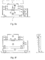
- FIG. 8e first shows the basic principle.
- the first actor Atl in Fig. 8e shifts part II in the x direction compared to the the base connected part I when the locations S1a and S1b be fired at alternately with the laser.
- Solid joints G1a and G1b enable this parallel shift.
- the second actuator moves part III in the y direction if the Positions S2a and S2b are fired at alternately.
- the parallel shift in the y direction is due to the solid elements G2a, b and G3a, b enables.
- 8f shows an implementation of the principle shown in Fig. 8e, with additional Solid-state joints G for mobility in the ⁇ direction provide an additional one with an actuator in the y / z plane z-adjustment of the lens holder 2 is made possible.
- the structure generally uses for the adjustment in the x and y direction.
- two flex elements for two-dimensional adjustment for example 8c, d or 8e, f
- another flex element for a one-dimensional adjustment that its z-movement over a flexible solid joint Gz transfers to the carrier plate 2.
- the solid body joint Gz is flexible with respect to the y movement and rigid for one Tensile load in the z direction.
Landscapes
- Physics & Mathematics (AREA)
- General Physics & Mathematics (AREA)
- Optics & Photonics (AREA)
- Optical Couplings Of Light Guides (AREA)
- Lens Barrels (AREA)
- Mounting And Adjusting Of Optical Elements (AREA)
- Laser Beam Processing (AREA)
Abstract
Description
- Fig. 1
- eine Ausführungsform einer erfindungsgemäßen Verstellvorrichtung mit linearen, stabförmigen Verstellelementen;
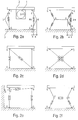
- Fig. 2a-f
- erfindungsgemäße Anordnungen von Verstellvorrichtungen;
- Fig. 3a-c
- eine Ausführungsform einer erfindungsgemäßen Verstellvorrichtung mit zweidimensionalen Verstellelementen;
- Fig. 4a,b
- eine Ausführungsform einer erfindungsgemäßen Verstellvorrichtung mit linearen Verstellelementen und flächigen Verbindungselementen;
- Fig.5a,b
- mit einem flächigen Verbindungselement verbundenes winkelförmiges Verstellelement in perspektivischer Ansicht (a) und Seitenansicht (b);
- Fig.6
- winkelförmiges Verstellelement, welches direkt mit Basisplatte und Trägerplatte verbunden ist;
- Fig.7a-d
- eine Ausführungsform einer erfindungsgemäßen Verstellvorrichtung mit drei winkelförmigen Verstellelementen in perspektivischen Ansichten (a,b) und Seitenansichten (c,d) bei Justagevorgängen;
- Fig.8a,b
- Verstellelemente für eine Justierung in einem Freiheitsgrad;
- Fig.8c,d
- Verstellelemente für eine Justierung in zwei Freiheitsgraden;
- Fig.8e,f
- Verstellelemente für eine unabhängige Justierung in zwei Freiheitsgraden;
- Fig.9
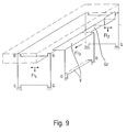
- Verstellvorrichtung für Justage in drei Freiheitsgraden.
Claims (20)
- Verstellvorrichtung, mitdadurch gekennzeichnet, daßeiner Anzahl Stellelemente (At), die durch lokale Beaufschlagung von Strahlungsenergie in ihrer Form veränderbar sind,die Stellelemente (At) an ihrem einen Ende mit einer ortsfesten Basisplatte (3) und an ihrem anderen Ende mit einer beweglichen Trägerplatte (2) verbunden sind.
- Verstellvorrichtung nach Anspruch 1,
dadurch gekennzeichnet, daßmindestens ein Stellelement (At) als lineares, insbesondere stabförmiges Stellelement ausgebildet ist, welches entlang einer Richtung in der Länge veränderbar ist (Fig.1). - Verstellvorrichtung nach Anspruch 1 oder 2,
dadurch gekennzeichnet, daßein erstes Stellelement (Atl) mit der Trägerplatte (2) in einem Abstand a von einem äußeren Rand der Trägerplatte (2) verbunden ist, undin einem Abstand b hiervon ein zweites Stellelement (At3) mit der Trägerplatte (2) verbunden ist, so daßmit dem ersten Stellelement (At1) eine Grobjustage und mit dem zweiten Stellelement (At3) eine Feinjustage mit dem Übersetzungsverhältnis a/(a+b) durchführbar ist (Fig.1). - Verstellvorrichtung nach einem der Ansprüche 1 bis 3,
dadurch gekennzeichnet, daßmindestens ein Stellelement eine Anzahl von zwei oder mehr Stellelementgliedern aufweist,die in Richtung der Normalen zwischen der Basisplatte (3) und der Trägerplatte (2) mit einem Abstand voneinander angeordnet und jeweils durch mindestens einen Steg (S) miteinander verbunden sind (Fig.8a-d). - Verstellvorrichtung nach einem der Ansprüche 1, 3 oder 4,
dadurch gekennzeichnet, daßmindestens ein Stellelement eine Anzahl von drei oder mehr Stellelementgliedern aufweist, die zwischen der Basisplatte (3) und der Trägerplatte (2) angeordnet sind, wobeimindestens zwei Stellelementglieder derart relativ zueinander angeordnet sind, daß sie in Richtung der Normalen zwischen der Basisplatte (3) und der Trägerplatte (2) mit einem Abstand voneinander angeordnet und durch mindestens einen Steg (S) miteinander verbunden sind,mindestens zwei Stellelementglieder derart relativ zueinander angeordnet sind, daß sie in einer lateralen Richtung voneinander beabstandet und durch mindestens einen Steg miteinander verbunden sind (Fig.8e,f). - Verstellvorrichtung nach Anspruch 1,
dadurch gekennzeichnet, daßmindestens ein Stellelement ein winkelförmiges Stellelement ist, welches zwei in einem Winkel zueinander angeordnete und durch ein Gelenk (G) verbundene ebene Abschnitte aufweist (Fig.5a,b, Fig.6). - Verstellvorrichtung nach Anspruch 6,
dadurch gekennzeichnet, daßmindestens zwei winkelförmige Stellelemente auf zwei gegenüberliegenden Seiten der Trägerplatte (2) angeordnet sind (Fig.7a-d). - Verstellvorrichtung nach Anspruch 6 oder 7,
dadurch gekennzeichnet, daßdas Gelenk durch reduzierte Materialstärke und/oder durch Aussparungen gebildet ist. - Verstellvorrichtung nach einem der vorhergehenden Ansprüche,
dadurch gekennzeichnet, daßmindestens ein Stellelement direkt mit der Basisplatte (3) und der Trägerplatte (2) verbunden ist (Fig.6). - Verstellvorrichtung nach Anspruch 9,
dadurch gekennzeichnet, daßmindestens eine dieser Verbindungen ein Gelenk (G) aufweist. - Verstellvorrichtung nach einem der Ansprüche 1 bis 8,
dadurch gekennzeichnet, daßmindestens ein Stellelement mit einem Winkelelement verbunden ist, welches zwei in einem Winkel zueinander angeordnete und durch ein Gelenk verbundene ebene Abschnitte aufweist, wobeidas Winkelelement mit seinen ebenen Abschnitten mit der Basisplatte (3) und der Trägerplatte (2) verbunden ist und mindestens eine dieser Verbindungen ein Gelenk (G) aufweist (Fig.5a,b). - Verstellvorrichtung nach Anspruch 10 oder 11,
dadurch gekennzeichnet, daßmindestens eines der Gelenke (G) durch reduzierte Materialstärke und/oder durch Aussparungen gebildet ist. - Verstellvorrichtung nach einem oder mehreren der vorhergehenden Ansprüche,
dadurch gekennzeichnet, daßauf der Trägerplatte (2) eine Linse (1) angeordnet ist. - Optoelektronische Sende-/Empfangseinrichtung, mitgekennzeichnet durcheinem Sende-/Empfangsbauelement,einer Anschlußöffnung für eine Lichtleitfaser, undeiner zwischen der Anschlußöffnung und dem Sende-/Empfangsbauelement angeordneten Linse (1),eine Verstellvorrichtung nach Anspruch 13.
- Optoelektronische Sende-/Empfangseinrichtung nach Anspruch 14,
dadurch gekennzeichnet, daßdas Sende-/Empfangsbauelement an der Verstellvorrichtung montiert ist. - Verfahren zum Justieren einer in den Ansprüchen 1 bis 15 genannten Verstellvorrichtung, bei welchemden Stellelementen an vorbestimmten Orten (S) Strahlungsenergie einer vorbestimmten Menge zugeführt wird.
- Verfahren nach den Ansprüchen 4, 5 und 16,
dadurch gekennzeichnet, daßdie Strahlungsenergie den Stegen (S) zugeführt wird. - Verfahren nach einem der Ansprüche 6 bis 8 sowie 16,
dadurch gekennzeichnet, daßdie Strahlungsenergie den ebenen Abschnitten zugeführt wird. - Verfahren nach Anspruch 17,
dadurch gekennzeichnet, daßfür eine Vergrößerung des Abstandes der Trägerplatte (2) von der Basisplatte (3) die Strahlungsenergie den der Basisplatte (3) zugewandten ebenen Abschnitten der Stellelemente zugeführt wird, undfür eine Verkleinerung des Abstandes der Trägerplatte (2) von der Basisplatte (3) die Strahlungsenergie den der Trägerplatte (2) zugewandten ebenen Abschnitten der Stellelemente zugeführt wird. - Verfahren nach einem der Ansprüche 16 bis 19,
dadurch gekennzeichnet, daßdie Strahlungsenergie durch einen Laserstrahl (LB) zugeführt wird.
Applications Claiming Priority (2)
| Application Number | Priority Date | Filing Date | Title |
|---|---|---|---|
| DE10037975A DE10037975C1 (de) | 2000-08-03 | 2000-08-03 | Verstellvorrichtung und Verfahren zu ihrer Justierung |
| DE10037975 | 2000-08-03 |
Publications (3)
| Publication Number | Publication Date |
|---|---|
| EP1186927A2 true EP1186927A2 (de) | 2002-03-13 |
| EP1186927A3 EP1186927A3 (de) | 2003-08-06 |
| EP1186927B1 EP1186927B1 (de) | 2005-06-08 |
Family
ID=7651267
Family Applications (1)
| Application Number | Title | Priority Date | Filing Date |
|---|---|---|---|
| EP01118126A Expired - Lifetime EP1186927B1 (de) | 2000-08-03 | 2001-07-26 | Verstellvorrichtung und Verfahren zu ihrer Justierung |
Country Status (4)
| Country | Link |
|---|---|
| US (1) | US6614605B2 (de) |
| EP (1) | EP1186927B1 (de) |
| JP (1) | JP3692059B2 (de) |
| DE (1) | DE10037975C1 (de) |
Cited By (4)
| Publication number | Priority date | Publication date | Assignee | Title |
|---|---|---|---|---|
| WO2002103417A3 (de) * | 2001-06-15 | 2003-10-02 | Finisar Corp | Justierverfahren, insbesondere laser-justierverfahren, und hierfür geeigneter aktor |
| US7356055B2 (en) | 2001-04-12 | 2008-04-08 | Finisar Corporation | Method and device for regulating the average wavelength of a laser, especially a semiconductor laser |
| US7862319B2 (en) | 2001-04-12 | 2011-01-04 | Finisar Corporation | Adjustment method, particularly a laser adjustment method, and an actuator suitable for the same |
| DE102017119508A1 (de) | 2017-08-25 | 2019-02-28 | BIAS Bremer Institut für angewandte Strahltechnik GmbH | Verfahren zum Verformen von Material mittels Laserstrahl |
Families Citing this family (11)
| Publication number | Priority date | Publication date | Assignee | Title |
|---|---|---|---|---|
| US7013071B2 (en) * | 2002-12-31 | 2006-03-14 | Intel Corporation | Method and device for achieving optical alignment using laser pulses |
| US7410088B2 (en) * | 2003-09-05 | 2008-08-12 | Matsushita Electric Industrial, Co., Ltd. | Solder preform for low heat stress laser solder attachment |
| US7021838B2 (en) * | 2003-12-16 | 2006-04-04 | Matsushita Electric Industrial Co., Ltd. | Optimizing alignment of an optical fiber to an optical output port |
| US7263260B2 (en) * | 2005-03-14 | 2007-08-28 | Matsushita Electric Industrial Co., Ltd. | Low cost, high precision multi-point optical component attachment |
| US7637065B2 (en) * | 2005-10-24 | 2009-12-29 | Usg Interiors, Inc. | Panel attachment clip |
| US7239107B1 (en) * | 2006-02-24 | 2007-07-03 | The Board Of Trustees Of The University Of Illinois | Flexure stage |
| US8310128B2 (en) * | 2008-05-07 | 2012-11-13 | The Board Of Trustees Of The University Of Illinois | High precision silicon-on-insulator MEMS parallel kinematic stages |
| DE102013215091A1 (de) * | 2013-08-01 | 2014-08-07 | Carl Zeiss Smt Gmbh | Optisches modul |
| JP6037974B2 (ja) * | 2013-08-20 | 2016-12-07 | 三菱電機株式会社 | 光送信機の製造方法 |
| US11364566B2 (en) * | 2018-08-09 | 2022-06-21 | The United States Of America As Represented By The Secretary Of The Army | Complex laser folding and fabrication |
| US11602806B2 (en) * | 2019-02-28 | 2023-03-14 | The United States Of America As Represented By The Secretary Of The Army | Method and apparatus for performing contactless laser fabrication and propulsion of freely moving structures |
Family Cites Families (16)
| Publication number | Priority date | Publication date | Assignee | Title |
|---|---|---|---|---|
| DE2918100A1 (de) * | 1979-05-04 | 1980-11-13 | Siemens Ag | Automatisiertes justieren in der feinwerktechnik |
| DE3026904C2 (de) * | 1980-07-16 | 1983-12-22 | Kunz Maschinen- und Apparatebau GmbH, 7850 Lörrach | Verschiebbare Lagerung für ein Wellen- bzw. Walzenlager |
| DE68920011T2 (de) * | 1988-03-22 | 1995-06-01 | Fujitsu Ltd | Optische halbleiteranordung und deren herstellung. |
| NL9100410A (nl) * | 1991-03-07 | 1992-10-01 | Asm Lithography Bv | Afbeeldingsapparaat voorzien van een focusfout- en/of scheefstandsdetectie-inrichting. |
| US5537276A (en) * | 1991-04-09 | 1996-07-16 | Matsushita Electric Industrial Co., Ltd. | Magnetic head installed on a rotary drum and method for adjusting the head height |
| BE1007436A3 (nl) * | 1993-08-11 | 1995-06-13 | Philips Electronics Nv | Werkwijze voor het onderling verplaatsen van tenminste twee delen van een actuator alsmede een actuator geschikt voor toepassing bij een dergelijke werkwijze. |
| US5724337A (en) * | 1993-10-29 | 1998-03-03 | Tdk Corporation | Optical pickup with a compact design |
| WO1996004592A1 (en) * | 1994-08-02 | 1996-02-15 | Philips Electronics N.V. | Method of repetitively imaging a mask pattern on a substrate |
| US5728240A (en) * | 1994-12-16 | 1998-03-17 | Sharp Kabushiki Kaisha | Positionally adjustable member and applications therefor |
| US5712463A (en) * | 1995-09-19 | 1998-01-27 | International Business Machines Corporation | Laser apparatus and method for adjusting the gram load static attitude and flying height of a slider in a head suspension assembly |
| DE19704502C1 (de) * | 1997-02-06 | 1998-02-26 | Siemens Ag | Lasermodul mit Ankoppeloptik und Verfahren zur Feinjustierung der Ankoppeloptik |
| US6002534A (en) * | 1997-04-09 | 1999-12-14 | Minolta Co., Ltd. | Optical apparatus with two optical systems and method for moving the two optical systems |
| US6030114A (en) * | 1997-09-30 | 2000-02-29 | Siemens Energy & Automation, Inc. | Method for thermally calibrating circuit breaker trip mechanism and associated trip mechanism |
| US6154952A (en) * | 1998-04-22 | 2000-12-05 | Hutchinson Technology, Inc. | Attachment isolation structures for adjusting head slider static attitude |
| DE19843965C2 (de) | 1998-09-24 | 2000-07-13 | Daimler Chrysler Ag | Halte- und Auslösemechanismus mit einem Formgedächtnis-Aktuator |
| JP3526224B2 (ja) * | 1998-10-20 | 2004-05-10 | シャープ株式会社 | 加工方法および光学部品 |
-
2000
- 2000-08-03 DE DE10037975A patent/DE10037975C1/de not_active Expired - Fee Related
-
2001
- 2001-07-26 EP EP01118126A patent/EP1186927B1/de not_active Expired - Lifetime
- 2001-08-03 JP JP2001236600A patent/JP3692059B2/ja not_active Expired - Fee Related
- 2001-08-03 US US09/922,374 patent/US6614605B2/en not_active Expired - Fee Related
Cited By (6)
| Publication number | Priority date | Publication date | Assignee | Title |
|---|---|---|---|---|
| US7356055B2 (en) | 2001-04-12 | 2008-04-08 | Finisar Corporation | Method and device for regulating the average wavelength of a laser, especially a semiconductor laser |
| US7862319B2 (en) | 2001-04-12 | 2011-01-04 | Finisar Corporation | Adjustment method, particularly a laser adjustment method, and an actuator suitable for the same |
| WO2002103417A3 (de) * | 2001-06-15 | 2003-10-02 | Finisar Corp | Justierverfahren, insbesondere laser-justierverfahren, und hierfür geeigneter aktor |
| US7679843B2 (en) | 2001-06-15 | 2010-03-16 | Finisar Corporation | Adjustment method, particularly a laser adjustment method, and an actuator suitable for the same |
| DE102017119508A1 (de) | 2017-08-25 | 2019-02-28 | BIAS Bremer Institut für angewandte Strahltechnik GmbH | Verfahren zum Verformen von Material mittels Laserstrahl |
| DE102017119508B4 (de) | 2017-08-25 | 2022-12-01 | BIAS Bremer Institut für angewandte Strahltechnik GmbH | Verfahren zum Verformen von Material mittels Laserstrahl |
Also Published As
| Publication number | Publication date |
|---|---|
| EP1186927B1 (de) | 2005-06-08 |
| JP3692059B2 (ja) | 2005-09-07 |
| US20020021480A1 (en) | 2002-02-21 |
| US6614605B2 (en) | 2003-09-02 |
| DE10037975C1 (de) | 2002-02-21 |
| EP1186927A3 (de) | 2003-08-06 |
| JP2002162547A (ja) | 2002-06-07 |
Similar Documents
| Publication | Publication Date | Title |
|---|---|---|
| EP1186927B1 (de) | Verstellvorrichtung und Verfahren zu ihrer Justierung | |
| EP0907906B1 (de) | Lithographie-belichtungseinrichtung | |
| DE19511593A1 (de) | Mikrooptische Vorrichtung | |
| EP0682279A1 (de) | Anordnung zur Ankopplung von optoelektronischen Komponenten und Lichtwellenleitern aneinander | |
| CH697142A5 (de) | Faser-Linsen-Anordnung sowie Linsen-Array für eine solche Faser-Linsen-Anordnung. | |
| DE102010031674A1 (de) | Lichtwellenleiter-Koppler | |
| DE69724331T2 (de) | Verfahren zur Herstellung eines Düsenkörpers und Arbeitsgerät | |
| DE102021120767A1 (de) | Laserverarbeitungsapparatur und Laserverarbeitungsverfahren | |
| DE69408752T2 (de) | Justiervorrichtung zur Ausrichtung optischer Fasern | |
| DE19923225B4 (de) | Optisches Element zur Umlenkung von Lichtstrahlen und Herstellungsverfahren | |
| DE60036032T2 (de) | Selbstausrichtende optomechanische crossbar-schalter | |
| EP1099139B1 (de) | Lithographieverfahren | |
| DE4490252B4 (de) | Leistungsgesteuertes fraktales Lasersystem | |
| DE19704502C1 (de) | Lasermodul mit Ankoppeloptik und Verfahren zur Feinjustierung der Ankoppeloptik | |
| EP1395859B1 (de) | Laserjustierbarer Aktor, optisches Bauelement und Justierverfahren | |
| EP1053576A1 (de) | Verfahren zum aufbauen und verbinden von optischen komponenten, insbesondere von optischen komponenten in einem laserresonator und laserresonator | |
| DE19613755A1 (de) | Optisches Koppelelement | |
| WO1998048495A2 (de) | Laservorrichtung | |
| DE4117449C1 (de) | ||
| DE202020107484U1 (de) | Laserprojektionsanordnung | |
| DE19942250A1 (de) | Lichtwellenleitung für die Laser-Schweißung | |
| DE102006039623B3 (de) | Verfahren und Vorrichtung zum Verbinden von wenigstens zwei Elementen | |
| DE102020202816A1 (de) | Mikrooptische Komponente sowie photonisches System | |
| DE102022127276B4 (de) | Lasersystem zur Erzeugung zumindest einer segmentierten Fokusstrahlung | |
| DE69903905T2 (de) | Methode zur Herstellung von Gittern in optischen Fasern |
Legal Events
| Date | Code | Title | Description |
|---|---|---|---|
| PUAI | Public reference made under article 153(3) epc to a published international application that has entered the european phase |
Free format text: ORIGINAL CODE: 0009012 |
|
| AK | Designated contracting states |
Kind code of ref document: A2 Designated state(s): AT BE CH CY DE DK ES FI FR GB GR IE IT LI LU MC NL PT SE TR |
|
| AX | Request for extension of the european patent |
Free format text: AL;LT;LV;MK;RO;SI |
|
| PUAL | Search report despatched |
Free format text: ORIGINAL CODE: 0009013 |
|
| AK | Designated contracting states |
Designated state(s): AT BE CH CY DE DK ES FI FR GB GR IE IT LI LU MC NL PT SE TR |
|
| AX | Request for extension of the european patent |
Extension state: AL LT LV MK RO SI |
|
| RIC1 | Information provided on ipc code assigned before grant |
Ipc: 7G 02B 6/32 B Ipc: 7G 02B 6/42 B Ipc: 7G 02B 7/02 A |
|
| 17P | Request for examination filed |
Effective date: 20030822 |
|
| 17Q | First examination report despatched |
Effective date: 20040224 |
|
| AKX | Designation fees paid |
Designated state(s): FR GB |
|
| REG | Reference to a national code |
Ref country code: DE Ref legal event code: 8566 |
|
| GRAP | Despatch of communication of intention to grant a patent |
Free format text: ORIGINAL CODE: EPIDOSNIGR1 |
|
| GRAS | Grant fee paid |
Free format text: ORIGINAL CODE: EPIDOSNIGR3 |
|
| GRAA | (expected) grant |
Free format text: ORIGINAL CODE: 0009210 |
|
| AK | Designated contracting states |
Kind code of ref document: B1 Designated state(s): FR GB |
|
| REG | Reference to a national code |
Ref country code: GB Ref legal event code: FG4D Free format text: NOT ENGLISH |
|
| PGFP | Annual fee paid to national office [announced via postgrant information from national office to epo] |
Ref country code: GB Payment date: 20050725 Year of fee payment: 5 |
|
| GBT | Gb: translation of ep patent filed (gb section 77(6)(a)/1977) |
Effective date: 20050816 |
|
| ET | Fr: translation filed | ||
| PLBE | No opposition filed within time limit |
Free format text: ORIGINAL CODE: 0009261 |
|
| STAA | Information on the status of an ep patent application or granted ep patent |
Free format text: STATUS: NO OPPOSITION FILED WITHIN TIME LIMIT |
|
| 26N | No opposition filed |
Effective date: 20060309 |
|
| REG | Reference to a national code |
Ref country code: FR Ref legal event code: TP |
|
| PG25 | Lapsed in a contracting state [announced via postgrant information from national office to epo] |
Ref country code: GB Free format text: LAPSE BECAUSE OF NON-PAYMENT OF DUE FEES Effective date: 20060726 |
|
| GBPC | Gb: european patent ceased through non-payment of renewal fee |
Effective date: 20060726 |
|
| PGFP | Annual fee paid to national office [announced via postgrant information from national office to epo] |
Ref country code: FR Payment date: 20070731 Year of fee payment: 7 |
|
| REG | Reference to a national code |
Ref country code: FR Ref legal event code: ST Effective date: 20111021 |
|
| PG25 | Lapsed in a contracting state [announced via postgrant information from national office to epo] |
Ref country code: FR Free format text: LAPSE BECAUSE OF NON-PAYMENT OF DUE FEES Effective date: 20060731 |