EP1186807A2 - Choke valve for automatic transmission - Google Patents
Choke valve for automatic transmission Download PDFInfo
- Publication number
- EP1186807A2 EP1186807A2 EP01121290A EP01121290A EP1186807A2 EP 1186807 A2 EP1186807 A2 EP 1186807A2 EP 01121290 A EP01121290 A EP 01121290A EP 01121290 A EP01121290 A EP 01121290A EP 1186807 A2 EP1186807 A2 EP 1186807A2
- Authority
- EP
- European Patent Office
- Prior art keywords
- valve
- gear
- shaft
- speed
- sub
- Prior art date
- Legal status (The legal status is an assumption and is not a legal conclusion. Google has not performed a legal analysis and makes no representation as to the accuracy of the status listed.)
- Granted
Links
Images


Classifications
-
- F—MECHANICAL ENGINEERING; LIGHTING; HEATING; WEAPONS; BLASTING
- F16—ENGINEERING ELEMENTS AND UNITS; GENERAL MEASURES FOR PRODUCING AND MAINTAINING EFFECTIVE FUNCTIONING OF MACHINES OR INSTALLATIONS; THERMAL INSULATION IN GENERAL
- F16H—GEARING
- F16H61/00—Control functions within control units of change-speed- or reversing-gearings for conveying rotary motion ; Control of exclusively fluid gearing, friction gearing, gearings with endless flexible members or other particular types of gearing
- F16H61/02—Control functions within control units of change-speed- or reversing-gearings for conveying rotary motion ; Control of exclusively fluid gearing, friction gearing, gearings with endless flexible members or other particular types of gearing characterised by the signals used
- F16H61/0262—Control functions within control units of change-speed- or reversing-gearings for conveying rotary motion ; Control of exclusively fluid gearing, friction gearing, gearings with endless flexible members or other particular types of gearing characterised by the signals used the signals being hydraulic
- F16H61/0276—Elements specially adapted for hydraulic control units, e.g. valves
-
- F—MECHANICAL ENGINEERING; LIGHTING; HEATING; WEAPONS; BLASTING
- F16—ENGINEERING ELEMENTS AND UNITS; GENERAL MEASURES FOR PRODUCING AND MAINTAINING EFFECTIVE FUNCTIONING OF MACHINES OR INSTALLATIONS; THERMAL INSULATION IN GENERAL
- F16H—GEARING
- F16H57/00—General details of gearing
- F16H57/04—Features relating to lubrication or cooling or heating
-
- F—MECHANICAL ENGINEERING; LIGHTING; HEATING; WEAPONS; BLASTING
- F16—ENGINEERING ELEMENTS AND UNITS; GENERAL MEASURES FOR PRODUCING AND MAINTAINING EFFECTIVE FUNCTIONING OF MACHINES OR INSTALLATIONS; THERMAL INSULATION IN GENERAL
- F16H—GEARING
- F16H61/00—Control functions within control units of change-speed- or reversing-gearings for conveying rotary motion ; Control of exclusively fluid gearing, friction gearing, gearings with endless flexible members or other particular types of gearing
- F16H61/0003—Arrangement or mounting of elements of the control apparatus, e.g. valve assemblies or snapfittings of valves; Arrangements of the control unit on or in the transmission gearbox
- F16H61/0009—Hydraulic control units for transmission control, e.g. assembly of valve plates or valve units
-
- F—MECHANICAL ENGINEERING; LIGHTING; HEATING; WEAPONS; BLASTING
- F16—ENGINEERING ELEMENTS AND UNITS; GENERAL MEASURES FOR PRODUCING AND MAINTAINING EFFECTIVE FUNCTIONING OF MACHINES OR INSTALLATIONS; THERMAL INSULATION IN GENERAL
- F16H—GEARING
- F16H61/00—Control functions within control units of change-speed- or reversing-gearings for conveying rotary motion ; Control of exclusively fluid gearing, friction gearing, gearings with endless flexible members or other particular types of gearing
- F16H61/02—Control functions within control units of change-speed- or reversing-gearings for conveying rotary motion ; Control of exclusively fluid gearing, friction gearing, gearings with endless flexible members or other particular types of gearing characterised by the signals used
- F16H61/0202—Control functions within control units of change-speed- or reversing-gearings for conveying rotary motion ; Control of exclusively fluid gearing, friction gearing, gearings with endless flexible members or other particular types of gearing characterised by the signals used the signals being electric
- F16H61/0251—Elements specially adapted for electric control units, e.g. valves for converting electrical signals to fluid signals
- F16H2061/0253—Details of electro hydraulic valves, e.g. lands, ports, spools or springs
Definitions
- the present invention relates to a choke valve for an automatic transmission provided within a valve body interposed between two separator plates.
- An automatic transmission includes hydraulic units such as a hydraulic clutch, a hydraulic brake and a torque converter.
- Various types of valve that control the operation of these units are each housed within a valve body on either face of which a separator plate is superimposed. By superimposing the separator plates on the opposite faces of the valve body in this way, it is possible to form oil passages between the separator plates and oil channels that are formed on the surface of the valve body.
- Such a hydraulic control system of an automatic transmission has a choke valve for controlling the flow rate of the oil according to the temperature conditions, as disclosed in Japanese Patent Application Laid-open No. 63-186058.
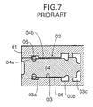
- a conventional choke valve 02 provided within a valve body 01 includes a valve hole 03 that opens on an end face of the plate-shaped valve body 01, a valve main body 04 that is fitted in the valve hole 03, and a clip 05 that prevents the valve main body 04 from falling out.
- Formed in the valve hole 03 are an inlet port 03a, an outlet port 03b and an air release port 03c.
- the valve main body 04 has a clip channel 04a with which the clip 05 engages and a small diameter section 04b.
- Formed between the inner periphery of the valve hole 03 and the outer periphery of the small diameter section 04b of the valve main body 04 is an annular choke 06.
- the inlet port 03a and the outlet port 03b communicate with each other via the choke 06.
- the present invention has been carried out in view of the above-mentioned circumstances and it is an object of the present invention to reduce the cost by simplifying the structure of a choke valve for an automatic transmission.
- a choke valve for an automatic transmission provided within a valve body interposed between two separator plates, wherein the choke valve is formed from a valve hole having a circular section that runs through the valve body in its thickness direction and a columnar valve main body that is fitted in the valve hole, the valve main body has a pair of annular channels formed on the outer periphery of the valve main body at opposite ends and a small diameter section formed between the two annular channels, the small diameter section together with the valve hole forming a choke, and a pair of ports formed between the two separator plates and oil channels formed on opposite faces of the valve body communicate with the pair of annular channels respectively.
- valve main body is fitted in the valve hole that runs through the valve body in its thickness direction and the valve main body is prevented from falling out by utilizing the separator plates that are superimposed on the valve body, it is unnecessary to employ special means such as a clip to prevent the valve main body from falling out, thus contributing to a reduction in the number of parts and the number of assembly steps.
- the pair of ports are formed between the two separator plates and the oil channels formed on the opposite faces of the valve body, it is unnecessary to make channels on the inner periphery of the valve hole so as to form the ports, thus reducing the number of machining steps and achieving a reduction in cost.
- valve main body is retained by a step formed on one end of the valve hole.
- retaining the valve main body by means of the step at one end of the valve hole can prevent the valve main body from falling out when it is provisionally assembled in the valve hole, thus making assembly of the separator plates easy.
- FIGS. 1 to 6 illustrate one embodiment of the present invention, where:
- the outer periphery of a four parallel shaft type automatic transmission T connected to the left-hand side face of an engine E comprises a torque converter case 11, a transmission case 12 and a case cover 13.
- the torque converter case 11 and the transmission case 12 support a main shaft Sm via ball bearings 14 and 15, a counter shaft Sc via a roller bearing 16 and a ball bearing 17, a first sub-shaft Ss1 via ball bearings 18 and 19, and a second sub-shaft Ss2 via a ball bearing 20 and a roller bearing 21.
- the main shaft Sm is connected to a crankshaft 22 of the engine E via a torque converter 23.
- a final drive gear 24 integral with the counter shaft Sc is meshed with a final driven gear 26 fixed on the outer periphery of a differential gear box 25 so as to drive right and left driven wheels WR and WL.
- a first speed clutch Cl and a second speed clutch C2 are provided on the first sub-shaft Ss1
- a third speed clutch C3 is provided on the second sub-shaft Ss2
- a fourth speed clutch C4 and a fifth speed - reverse clutch C5R are provided on the main shaft Sm.
- a sub-shaft drive first gear 31 integral with the main shaft Sm is meshed with a sub-shaft drive second gear 32 supported on the counter shaft Sc in a relatively rotatable manner.
- This sub-shaft drive second gear 32 is also meshed with a sub-shaft drive third gear 33 integral with the first sub-shaft Ss1, and the above-mentioned sub-shaft drive first gear 31 is meshed with a sub-shaft drive fourth gear 34 supported on the second sub-shaft Ss2 in a relatively rotatable manner.
- the first sub-shaft Ss1 having the integral sub-shaft drive third gear 33 meshed with the above-mentioned sub-shaft drive second gear 32 always rotates and the clutch outers 36 and 37 of the first speed clutch C1 and the second speed clutch C2 provided on this first sub-shaft Ss1 also always rotate.
- the sub-shaft drive fourth gear 34 supported on the second sub-shaft Ss2 in a relatively rotatable manner and meshed with the sub-shaft drive first gear 31, and a clutch inner 38 of the third speed clutch C3 connected integrally to this sub-shaft drive fourth gear 34 also always rotate.
- a first sub first speed gear 40 integral with a clutch inner 39 of the first speed clutch C1 provided on the first sub-shaft Ss1 is meshed with a counter first speed gear 41 integral with the counter shaft Sc.
- a first sub second speed gear 43 integral with a clutch inner 42 of the second speed clutch C2 provided on the first sub-shaft Ss1 is meshed with a counter second speed gear 44 integral with the counter shaft Sc.
- a clutch outer 45 of the third speed clutch C3 and a second sub third speed gear 46 are integrally provided on the second sub-shaft Ss2.
- a main third speed - fourth speed gear 48 integral with a clutch inner 47 of the fourth speed clutch C4 provided on the main shaft Sm is meshed with the above-mentioned second sub third speed gear 46 integral with the second sub-shaft Ss2.
- a main fifth speed gear 50 and a main reverse gear 51 are provided integrally with a clutch inner 49 of the fifth speed - reverse clutch C5R provided on the main shaft Sm.
- a counter third speed - fourth speed gear 52 integral with the counter shaft Sc is meshed with the above-mentioned main third speed - fourth speed gear 48.
- a counter fifth speed gear 53 and a counter reverse gear 54 are supported on the counter shaft Sc in a relatively rotatable manner.
- the counter fifth speed gear 53 is meshed with the above-mentioned main fifth speed gear 50
- the counter reverse gear 54 is meshed with the above-mentioned main reverse gear 51 via a reverse idle gear 55 (see FIG. 1).
- the counter fifth speed gear 53 and the counter reverse gear 54 on the counter shaft Sc can be selectively coupled to the counter shaft Sc by means of a chamfer 56.
- the rotation of the main shaft Sm is transmitted to the driven wheels WR and WL through the sub-shaft drive first gear 31, then the sub-shaft drive second gear 32, the sub-shaft drive third gear 33, the first sub-shaft Ss1, the clutch outer 36 and the clutch inner 39 of the first speed clutch C1, the first sub first speed gear 40, the counter first speed gear 41, the counter shaft Sc, the final drive gear 24, the final driven gear 26 and the differential gear box 25.
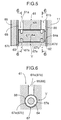
- a choke valve V has a valve hole 64 having a circular section that runs through the valve body 61 in its thickness direction.
- a step 64a is formed on one end of the valve hole 64 that opens on the first separator plate 62 side.
- the above-mentioned valve hole 64 and the step 64a can be formed simultaneously by leaving a part of the prepared hole.
- Formed on opposite faces of the valve body 61 are oil channels 61a and 61b that communicate with the valve hole 64.
- An inlet port 65 is formed between the oil channel 61a and the second separator plate 63 and an outlet port 66 is formed between the oil channel 61b and the first separator plate 62.
- a columnar valve main body 67 that is fitted in the valve hole 64 has a first annular channel 67a and a second annular channel 67b near its opposite ends.
- Support parts 67c and 67d having an outer diameter equal to the inner diameter of the valve hole 64 are formed on the opposite outer sides in the axial direction of the valve main body 67.
- a small diameter section 67e having a diameter that is slightly smaller than the inner diameter of the valve hole 64 is formed between the first and second annular channels 67a and 67b.
- the first annular channel 67a and the second annular channel and 67b communicate with the inlet port 65 and the outlet port 66 respectively.
- the inlet port 65 and the outlet port 66 communicate with each other via an annular choke 68 formed between the valve hole 64 and the small diameter section 67e.
- an annular choke 68 formed between the valve hole 64 and the small diameter section 67e.
- the first separator plate 62, the second separator plate 63 and the cover plate 69 are superimposed on the opposite faces of the valve body 61 and the assembly can be fastened to the left-hand side face of the torque converter case 11. Because the valve main body 67 is retained by the step 64a of the valve hole 64 so that it does not fall out, the operability can be enhanced.
- valve main body 67 is prevented from falling out of the valve hole 64 by the second separator plate 63, it is unnecessary to employ special means such as a clip to prevent the valve main body from falling out, thus achieving a reduction in the number of parts and the number of assembly steps.
- outlet port 66 and the inlet port 65 are formed between the first and second separator plates 62 and 63 and the oil channels 61b and 61a formed on the opposite faces of the valve body 61 respectively, it is unnecessary to make channels on the inner periphery of the valve hole 64 with great effort so as to form the ports, thus reducing the number of machining steps and achieving a reduction in the cost.
- a choke valve for an automatic transmission is formed from a valve hole having a circular section that runs through a valve body in its thickness direction and a columnar valve main body that is fitted in the valve hole.
- the valve main body has a pair of annular channels formed on the outer periphery of the valve main body at opposite ends and a small diameter section formed between the two annular channels, the small diameter section together with the valve hole forming a choke.
- An inlet port and an outlet port formed between two separator plates and oil channels formed on opposite faces of the valve body communicate with the pair of annular channels, respectively.
Landscapes
- Engineering & Computer Science (AREA)
- General Engineering & Computer Science (AREA)
- Mechanical Engineering (AREA)
- Control Of Transmission Device (AREA)
- General Details Of Gearings (AREA)
- Gear-Shifting Mechanisms (AREA)
Abstract
Description
- The present invention relates to a choke valve for an automatic transmission provided within a valve body interposed between two separator plates.
- An automatic transmission includes hydraulic units such as a hydraulic clutch, a hydraulic brake and a torque converter. Various types of valve that control the operation of these units are each housed within a valve body on either face of which a separator plate is superimposed. By superimposing the separator plates on the opposite faces of the valve body in this way, it is possible to form oil passages between the separator plates and oil channels that are formed on the surface of the valve body. Such a hydraulic control system of an automatic transmission has a choke valve for controlling the flow rate of the oil according to the temperature conditions, as disclosed in Japanese Patent Application Laid-open No. 63-186058.
- As shown in FIG. 7, a
conventional choke valve 02 provided within avalve body 01 includes avalve hole 03 that opens on an end face of the plate-shaped valve body 01, a valvemain body 04 that is fitted in thevalve hole 03, and aclip 05 that prevents the valvemain body 04 from falling out. Formed in thevalve hole 03 are aninlet port 03a, anoutlet port 03b and anair release port 03c. The valvemain body 04 has aclip channel 04a with which theclip 05 engages and asmall diameter section 04b. Formed between the inner periphery of thevalve hole 03 and the outer periphery of thesmall diameter section 04b of the valvemain body 04 is anannular choke 06. Theinlet port 03a and theoutlet port 03b communicate with each other via thechoke 06. - With regard to the
conventional choke valve 02 shown in FIG. 7, because it is necessary to machine out the inner periphery of thevalve hole 03 so as to form theinlet port 03a and theoutlet port 03b, the number of machining steps increases. Furthermore, because it is necessary to employ theclip 05 in order to prevent the valvemain body 04 from falling out, the number of parts increases. - The present invention has been carried out in view of the above-mentioned circumstances and it is an object of the present invention to reduce the cost by simplifying the structure of a choke valve for an automatic transmission.
- In order to achieve the above-mentioned object, there is proposed a choke valve for an automatic transmission provided within a valve body interposed between two separator plates, wherein the choke valve is formed from a valve hole having a circular section that runs through the valve body in its thickness direction and a columnar valve main body that is fitted in the valve hole, the valve main body has a pair of annular channels formed on the outer periphery of the valve main body at opposite ends and a small diameter section formed between the two annular channels, the small diameter section together with the valve hole forming a choke, and a pair of ports formed between the two separator plates and oil channels formed on opposite faces of the valve body communicate with the pair of annular channels respectively.
- In accordance with the above-mentioned arrangement, because the valve main body is fitted in the valve hole that runs through the valve body in its thickness direction and the valve main body is prevented from falling out by utilizing the separator plates that are superimposed on the valve body, it is unnecessary to employ special means such as a clip to prevent the valve main body from falling out, thus contributing to a reduction in the number of parts and the number of assembly steps. Moreover, because the pair of ports are formed between the two separator plates and the oil channels formed on the opposite faces of the valve body, it is unnecessary to make channels on the inner periphery of the valve hole so as to form the ports, thus reducing the number of machining steps and achieving a reduction in cost.
- Furthermore, there is proposed a choke valve for an automatic transmission wherein the valve main body is retained by a step formed on one end of the valve hole.
- In accordance with the above-mentioned arrangement, retaining the valve main body by means of the step at one end of the valve hole can prevent the valve main body from falling out when it is provisionally assembled in the valve hole, thus making assembly of the separator plates easy.
- Modes for carrying out the present invention are described below by reference to a preferred exemplary embodiment of the present invention shown in the attached drawings.
- FIGS. 1 to 6 illustrate one embodiment of the present invention, where:
- FIG. 1 is a schematic diagram showing a four parallel shaft type automatic transmission;
- FIG. 2 is a diagram showing the positions of sections A and B of the transmission;
- FIG. 3 is a detailed cross-section of section A in FIG. 2;
- FIG. 4 is a detailed cross-section of section B in FIG. 2;
- FIG. 5 is a magnified cross-section of the essential part of FIG. 3;
- FIG. 6 is a view from a line 6-6 in FIG. 5; and
- FIG. 7 is a cross-section showing the structure of a conventional choke valve.
-
- As shown in FIGS. 1 to 4, the outer periphery of a four parallel shaft type automatic transmission T connected to the left-hand side face of an engine E comprises a
torque converter case 11, atransmission case 12 and acase cover 13. Thetorque converter case 11 and thetransmission case 12 support a main shaft Sm viaball bearings ball bearings crankshaft 22 of the engine E via atorque converter 23. Afinal drive gear 24 integral with the counter shaft Sc is meshed with a final drivengear 26 fixed on the outer periphery of adifferential gear box 25 so as to drive right and left driven wheels WR and WL. - In order to establish a first speed gear shift stage to a fifth speed gear shift stage and a reverse gear shift stage by transmitting the rotation of the main shaft Sm to the counter shaft Sc at the respective gear ratios, a first speed clutch Cl and a second speed clutch C2 are provided on the first sub-shaft Ss1, a third speed clutch C3 is provided on the second sub-shaft Ss2, and a fourth speed clutch C4 and a fifth speed - reverse clutch C5R are provided on the main shaft Sm. A sub-shaft drive
first gear 31 integral with the main shaft Sm is meshed with a sub-shaft drivesecond gear 32 supported on the counter shaft Sc in a relatively rotatable manner. This sub-shaft drivesecond gear 32 is also meshed with a sub-shaft drivethird gear 33 integral with the first sub-shaft Ss1, and the above-mentioned sub-shaft drivefirst gear 31 is meshed with a sub-shaft drivefourth gear 34 supported on the second sub-shaft Ss2 in a relatively rotatable manner. - Even when the first speed clutch C1 to the fifth speed - reverse clutch C5R are in a disengaged state, each of the parts explained below always rotates as a result of being operable in association with rotation of the main shaft Sm. That is to say, the sub-shaft drive
first gear 31 integral with the main shaft Sm and a clutch outer 35 integral with the main shaft Sm, the clutch outer 35 being common to both the fourth speed clutch C4 and the fifth speed-reverse clutch C5R, always rotate, and the sub-shaft drivesecond gear 32 of the counter shaft Sc that is meshed with the sub-shaft drivefirst gear 31 of the main sub-shaft Sm always rotates. The first sub-shaft Ss1 having the integral sub-shaft drivethird gear 33 meshed with the above-mentioned sub-shaft drivesecond gear 32 always rotates and theclutch outers fourth gear 34 supported on the second sub-shaft Ss2 in a relatively rotatable manner and meshed with the sub-shaft drivefirst gear 31, and a clutch inner 38 of the third speed clutch C3 connected integrally to this sub-shaft drivefourth gear 34 also always rotate. - A first sub
first speed gear 40 integral with a clutch inner 39 of the first speed clutch C1 provided on the first sub-shaft Ss1 is meshed with a counterfirst speed gear 41 integral with the counter shaft Sc. A first subsecond speed gear 43 integral with a clutch inner 42 of the second speed clutch C2 provided on the first sub-shaft Ss1 is meshed with a countersecond speed gear 44 integral with the counter shaft Sc. A clutch outer 45 of the third speed clutch C3 and a second subthird speed gear 46 are integrally provided on the second sub-shaft Ss2. A main third speed -fourth speed gear 48 integral with a clutch inner 47 of the fourth speed clutch C4 provided on the main shaft Sm is meshed with the above-mentioned second subthird speed gear 46 integral with the second sub-shaft Ss2. A mainfifth speed gear 50 and a mainreverse gear 51 are provided integrally with a clutch inner 49 of the fifth speed - reverse clutch C5R provided on the main shaft Sm. - A counter third speed -
fourth speed gear 52 integral with the counter shaft Sc is meshed with the above-mentioned main third speed -fourth speed gear 48. A counterfifth speed gear 53 and acounter reverse gear 54 are supported on the counter shaft Sc in a relatively rotatable manner. The counterfifth speed gear 53 is meshed with the above-mentioned mainfifth speed gear 50, and thecounter reverse gear 54 is meshed with the above-mentioned mainreverse gear 51 via a reverse idle gear 55 (see FIG. 1). The counterfifth speed gear 53 and thecounter reverse gear 54 on the counter shaft Sc can be selectively coupled to the counter shaft Sc by means of achamfer 56. - When the first speed clutch C1 is engaged so as to establish a first speed gear shift stage, the rotation of the main shaft Sm is transmitted to the driven wheels WR and WL through the sub-shaft drive
first gear 31, then the sub-shaft drivesecond gear 32, the sub-shaft drivethird gear 33, the first sub-shaft Ss1, the clutch outer 36 and the clutch inner 39 of the first speed clutch C1, the first subfirst speed gear 40, the counterfirst speed gear 41, the counter shaft Sc, thefinal drive gear 24, the final drivengear 26 and thedifferential gear box 25. - When the second speed clutch C2 is engaged so as to establish a second speed gear shift stage, the rotation of the main shaft Sm is transmitted to the driven wheels WR and WL through the sub-shaft drive
first gear 31, then the sub-shaft drivesecond gear 32, the sub-shaft drivethird gear 33, the first sub-shaft Ss1, the clutch outer 37 and the clutch inner 42 of the second speed clutch C2, the first subsecond speed gear 43, the countersecond speed gear 44, the counter shaft Sc, thefinal drive gear 24, the final drivengear 26 and thedifferential gear box 25. - When the third speed clutch C3 is engaged so as to establish a third speed gear shift stage, the rotation of the main shaft Sm is transmitted to the driven wheels WR and WL through the sub-shaft drive
first gear 31, then the sub-shaft drivefourth gear 34, the clutch inner 38 and the clutch outer 45 of the third speed clutch C3, the second sub-shaft Ss2, the second subthird speed gear 46, the main third speed -fourth speed gear 48, the counter third speed -fourth speed gear 52, the counter shaft Sc, thefinal drive gear 24, the final drivengear 26 and thedifferential gear box 25. - When the fourth speed clutch C4 is engaged so as to establish a fourth speed gear shift stage, the rotation of the main shaft Sm is transmitted to the driven wheels WR and WL through the clutch outer 35 and the clutch inner 47 of the fourth speed clutch C4, the main third speed -
fourth speed gear 48, the counter third speed -fourth speed gear 52, the counter shaft Sc, thefinal drive gear 24, the final drivengear 26 and thedifferential gear box 25. - When the fifth speed - reverse clutch C5R is engaged so as to establish a fifth speed gear shift stage in a state in which the counter
fifth speed gear 53 is coupled to the counter shaft Sc by means of thechamfer 56, the rotation of the main shaft Sm is transmitted to the driven wheels WR and WL through the clutch outer 35 and the clutch inner 49 of the fifth speed - reverse clutch C5R, the mainfifth speed gear 50, the counterfifth speed gear 53, the counter shaft Sc, thefinal drive gear 24, the final drivengear 26 and thedifferential gear box 25. - When the fifth speed - reverse clutch C5R is engaged so as to establish a reverse gear shift stage in a state in which the counter
reverse gear 54 is coupled to the counter shaft Sc by means of thechamfer 56, the rotation of the main shaft Sm is transmitted to the driven wheels WR and WL through the clutch outer 35 and the clutch inner 49 of the fifth speed - reverse clutch C5R, the mainreverse gear 51, thereverse idle gear 55, thecounter reverse gear 54, the counter shaft Sc, thefinal drive gear 24, the final drivengear 26 and thedifferential gear box 25. - As is clear from FIGS. 5 and 6, superimposed on and fixed to the left-hand side face of the
torque converter case 11 are afirst separator plate 62, avalve body 61, asecond separator plate 63 and acover plate 69. A choke valve V has avalve hole 64 having a circular section that runs through thevalve body 61 in its thickness direction. Astep 64a is formed on one end of thevalve hole 64 that opens on thefirst separator plate 62 side. When finishing a prepared hole that has been formed during casting of thevalve body 61, the above-mentionedvalve hole 64 and thestep 64a can be formed simultaneously by leaving a part of the prepared hole. Formed on opposite faces of thevalve body 61 areoil channels valve hole 64. Aninlet port 65 is formed between theoil channel 61a and thesecond separator plate 63 and anoutlet port 66 is formed between theoil channel 61b and thefirst separator plate 62. - A columnar valve
main body 67 that is fitted in thevalve hole 64 has a firstannular channel 67a and a secondannular channel 67b near its opposite ends.Support parts valve hole 64 are formed on the opposite outer sides in the axial direction of the valvemain body 67. Asmall diameter section 67e having a diameter that is slightly smaller than the inner diameter of thevalve hole 64 is formed between the first and secondannular channels annular channel 67a and the second annular channel and 67b communicate with theinlet port 65 and theoutlet port 66 respectively. Theinlet port 65 and theoutlet port 66 communicate with each other via anannular choke 68 formed between thevalve hole 64 and thesmall diameter section 67e. When the oil that flows in via theinlet port 65 passes through thechoke 68 of the choke valve V and flows out via theoutlet port 66, the flow rate of the oil can be controlled according to the temperature conditions. - When assembling the choke valve V, while inserting the valve
main body 67 into thevalve hole 64 of thevalve body 61 and retaining it with thestep 64a, thefirst separator plate 62, thesecond separator plate 63 and thecover plate 69 are superimposed on the opposite faces of thevalve body 61 and the assembly can be fastened to the left-hand side face of thetorque converter case 11. Because the valvemain body 67 is retained by thestep 64a of thevalve hole 64 so that it does not fall out, the operability can be enhanced. Moreover, because the valvemain body 67 is prevented from falling out of thevalve hole 64 by thesecond separator plate 63, it is unnecessary to employ special means such as a clip to prevent the valve main body from falling out, thus achieving a reduction in the number of parts and the number of assembly steps. Furthermore, because theoutlet port 66 and theinlet port 65 are formed between the first andsecond separator plates oil channels valve body 61 respectively, it is unnecessary to make channels on the inner periphery of thevalve hole 64 with great effort so as to form the ports, thus reducing the number of machining steps and achieving a reduction in the cost. - An embodiment of the present invention has been described in detail above, but the present invention can be modified in a variety of ways without departing from the spirit and scope of the invention.
- A choke valve for an automatic transmission is formed from a valve hole having a circular section that runs through a valve body in its thickness direction and a columnar valve main body that is fitted in the valve hole. The valve main body has a pair of annular channels formed on the outer periphery of the valve main body at opposite ends and a small diameter section formed between the two annular channels, the small diameter section together with the valve hole forming a choke. An inlet port and an outlet port formed between two separator plates and oil channels formed on opposite faces of the valve body communicate with the pair of annular channels, respectively. Thus, the structure of the choke valve for an automatic transmission is simplified, thereby reducing the cost.
Claims (2)
- A choke valve for an automatic transmission, the choke valve being provided in a valve body interposed between two separator plates, comprising:a valve hole having a circular section that runs through the valve body in its thickness direction, anda columnar valve main body that is fitted in the valve hole,wherein the valve main body has a pair of annular channels formed on the outer periphery of the valve main body at opposite ends and a small diameter section formed between the two annular channels, the small diameter section together with the valve hole forming a choke, andwherein a pair of ports formed between the two separator plates and oil channels formed on opposite faces of the valve body communicate with the pair of annular channels respectively.
- The choke valve for an automatic transmission according to Claim 1,
wherein the valve main body is retained by a step formed on one end of the valve hole.
Applications Claiming Priority (2)
| Application Number | Priority Date | Filing Date | Title |
|---|---|---|---|
| JP2000273250 | 2000-09-08 | ||
| JP2000273250A JP4414077B2 (en) | 2000-09-08 | 2000-09-08 | Choke valve for automatic transmission |
Publications (3)
| Publication Number | Publication Date |
|---|---|
| EP1186807A2 true EP1186807A2 (en) | 2002-03-13 |
| EP1186807A3 EP1186807A3 (en) | 2007-08-01 |
| EP1186807B1 EP1186807B1 (en) | 2008-09-03 |
Family
ID=18759234
Family Applications (1)
| Application Number | Title | Priority Date | Filing Date |
|---|---|---|---|
| EP01121290A Expired - Lifetime EP1186807B1 (en) | 2000-09-08 | 2001-09-05 | Choke valve for automatic transmission |
Country Status (4)
| Country | Link |
|---|---|
| US (1) | US6615873B2 (en) |
| EP (1) | EP1186807B1 (en) |
| JP (1) | JP4414077B2 (en) |
| DE (1) | DE60135612D1 (en) |
Families Citing this family (1)
| Publication number | Priority date | Publication date | Assignee | Title |
|---|---|---|---|---|
| JP6005384B2 (en) * | 2012-04-02 | 2016-10-12 | 本田技研工業株式会社 | Lubricating oil supply device for transmission |
Citations (1)
| Publication number | Priority date | Publication date | Assignee | Title |
|---|---|---|---|---|
| JPS63186058A (en) | 1987-01-29 | 1988-08-01 | Honda Motor Co Ltd | Control device for hydraulically operated transmission for vehicles |
Family Cites Families (23)
| Publication number | Priority date | Publication date | Assignee | Title |
|---|---|---|---|---|
| US3053051A (en) * | 1962-09-11 | Transmission | ||
| US3381698A (en) * | 1964-03-16 | 1968-05-07 | Sanders Associates Inc | Adjustable pressure gain control servo valve system |
| US3465614A (en) * | 1968-02-02 | 1969-09-09 | Ford Motor Co | Power transmission control system with temperature compensation |
| US3515161A (en) * | 1968-05-06 | 1970-06-02 | Honeywell Inc | Flow control apparatus |
| US3556155A (en) * | 1969-01-24 | 1971-01-19 | Caterpillar Tractor Co | Variable flow-modulated valve |
| US3592230A (en) * | 1969-04-23 | 1971-07-13 | Self Matic Valves Corp | Back pressure directional control valves employing pilot air of low volume and pressure |
| US3566716A (en) * | 1969-07-22 | 1971-03-02 | Int Harvester Co | Clutch cylinder circuit and charging valve therefor |
| US3789880A (en) * | 1972-01-04 | 1974-02-05 | Chem Valley Machines Inc | Porous metal flow control spool |
| US3978891A (en) * | 1972-10-02 | 1976-09-07 | The Bendix Corporation | Quieting means for a fluid flow control device |
| US3964372A (en) * | 1973-04-02 | 1976-06-22 | International Harvester Company | Clutch cylinder circuit and charging valve therefor |
| US4069843A (en) * | 1973-04-02 | 1978-01-24 | International Harvester Company | Clutch cylinder circuit and charging valve therefor |
| US4108210A (en) * | 1973-10-09 | 1978-08-22 | Fisher Controls Company | Control valve trim assembly |
| DE2352939C2 (en) * | 1973-10-23 | 1984-07-05 | Robert Bosch Gmbh, 7000 Stuttgart | Hydraulic control device, in particular for a gear change device in automatic motor vehicle transmissions |
| US3995664A (en) * | 1975-03-13 | 1976-12-07 | Nelson Walter R | Flow control device |
| US4022384A (en) * | 1975-12-08 | 1977-05-10 | Hancor, Inc. | Irrigation tubing |
| US4220173A (en) * | 1978-07-31 | 1980-09-02 | Brien John W O | Time delay fluid valve |
| FR2469200A1 (en) * | 1979-11-13 | 1981-05-22 | Fives Cail Babcock | HOMOGENEIZING DEVICE FOR LIQUID OR PASTY PRODUCTS |
| US4460129A (en) * | 1980-02-13 | 1984-07-17 | Olson Donald O | Turbulent flow emitter |
| JPS6084457A (en) * | 1983-10-14 | 1985-05-13 | Nissan Motor Co Ltd | Control valve for automatic transmission |
| US5749650A (en) * | 1997-03-13 | 1998-05-12 | Apv Homogenizer Group, A Division Of Apv North America, Inc. | Homogenization valve |
| US5890509A (en) * | 1997-03-31 | 1999-04-06 | Ford Global Technologies, Inc. | Hydraulic temperature compensated cooler bypass control for an automatic transmission |
| US5863129A (en) * | 1998-01-05 | 1999-01-26 | Gary A. Smith | Serial resin mixing devices |
| DE19812274B4 (en) * | 1998-03-20 | 2013-12-12 | Zf Friedrichshafen Ag | Device for venting a clutch in a vehicle transmission |
-
2000
- 2000-09-08 JP JP2000273250A patent/JP4414077B2/en not_active Expired - Fee Related
-
2001
- 2001-09-05 DE DE60135612T patent/DE60135612D1/en not_active Expired - Lifetime
- 2001-09-05 EP EP01121290A patent/EP1186807B1/en not_active Expired - Lifetime
- 2001-09-06 US US09/946,973 patent/US6615873B2/en not_active Expired - Lifetime
Patent Citations (1)
| Publication number | Priority date | Publication date | Assignee | Title |
|---|---|---|---|---|
| JPS63186058A (en) | 1987-01-29 | 1988-08-01 | Honda Motor Co Ltd | Control device for hydraulically operated transmission for vehicles |
Also Published As
| Publication number | Publication date |
|---|---|
| DE60135612D1 (en) | 2008-10-16 |
| EP1186807B1 (en) | 2008-09-03 |
| JP2002081531A (en) | 2002-03-22 |
| US20020035007A1 (en) | 2002-03-21 |
| JP4414077B2 (en) | 2010-02-10 |
| US6615873B2 (en) | 2003-09-09 |
| EP1186807A3 (en) | 2007-08-01 |
Similar Documents
| Publication | Publication Date | Title |
|---|---|---|
| US8689654B2 (en) | Hydraulic pressure supply apparatus for transmission | |
| US20090200134A1 (en) | Vehicular transmission | |
| US4010833A (en) | Clutch assembly for planetary-gear trains | |
| US8978500B2 (en) | Hydraulic pressure supply apparatus for transmission | |
| US20120216883A1 (en) | Hydraulic controls for an automatic transmission | |
| JP2009085389A (en) | Automatic transmission | |
| US11180022B2 (en) | Vehicle transmission and drive system | |
| US5480361A (en) | Change direction planetary gearing for continuously variable transmission | |
| US6923091B2 (en) | Internal combustion engine with hydraulically operated automatic transmission | |
| JPH0448980B2 (en) | ||
| CA2406943C (en) | Transmission | |
| EP1186807B1 (en) | Choke valve for automatic transmission | |
| EP1191257B1 (en) | Vehicle transmission | |
| JP2007261302A (en) | Power transmission device for hybrid vehicle | |
| US6860366B2 (en) | Oil passage structure in rotary shaft | |
| CA2356769C (en) | Vehicle transmission | |
| JP2003139167A (en) | Hydraulic control mechanism of automatic transmission | |
| JPH08159170A (en) | Lubricating structure for synchromesh device | |
| US4359145A (en) | Demountable clutch support for gear transmission | |
| JP2005233386A (en) | Lubrication structure of automatic transmission | |
| US20050061094A1 (en) | Hydraulic port separator in an automatic transmission | |
| CN215244311U (en) | Hybrid power system | |
| JPH08285062A (en) | Hydraulic control for automatic transmission | |
| JPH0510346A (en) | Gear transmission | |
| JPH0765645B2 (en) | Oil passage structure of automatic transmission |
Legal Events
| Date | Code | Title | Description |
|---|---|---|---|
| PUAI | Public reference made under article 153(3) epc to a published international application that has entered the european phase |
Free format text: ORIGINAL CODE: 0009012 |
|
| 17P | Request for examination filed |
Effective date: 20010905 |
|
| AK | Designated contracting states |
Kind code of ref document: A2 Designated state(s): AT BE CH CY DE DK ES FI FR GB GR IE IT LI LU MC NL PT SE TR |
|
| AX | Request for extension of the european patent |
Free format text: AL;LT;LV;MK;RO;SI |
|
| PUAL | Search report despatched |
Free format text: ORIGINAL CODE: 0009013 |
|
| AK | Designated contracting states |
Kind code of ref document: A3 Designated state(s): AT BE CH CY DE DK ES FI FR GB GR IE IT LI LU MC NL PT SE TR |
|
| AX | Request for extension of the european patent |
Extension state: AL LT LV MK RO SI |
|
| RIC1 | Information provided on ipc code assigned before grant |
Ipc: F16H 57/04 20060101ALI20070627BHEP Ipc: F16H 61/00 20060101ALI20070627BHEP Ipc: F16H 59/72 20060101ALI20070627BHEP Ipc: F15B 21/04 20060101AFI20070627BHEP |
|
| GRAP | Despatch of communication of intention to grant a patent |
Free format text: ORIGINAL CODE: EPIDOSNIGR1 |
|
| AKX | Designation fees paid |
Designated state(s): DE GB |
|
| GRAS | Grant fee paid |
Free format text: ORIGINAL CODE: EPIDOSNIGR3 |
|
| GRAA | (expected) grant |
Free format text: ORIGINAL CODE: 0009210 |
|
| AK | Designated contracting states |
Kind code of ref document: B1 Designated state(s): DE GB |
|
| REG | Reference to a national code |
Ref country code: GB Ref legal event code: FG4D |
|
| REF | Corresponds to: |
Ref document number: 60135612 Country of ref document: DE Date of ref document: 20081016 Kind code of ref document: P |
|
| PLBE | No opposition filed within time limit |
Free format text: ORIGINAL CODE: 0009261 |
|
| STAA | Information on the status of an ep patent application or granted ep patent |
Free format text: STATUS: NO OPPOSITION FILED WITHIN TIME LIMIT |
|
| 26N | No opposition filed |
Effective date: 20090604 |
|
| REG | Reference to a national code |
Ref country code: GB Ref legal event code: 746 Effective date: 20120521 |
|
| REG | Reference to a national code |
Ref country code: DE Ref legal event code: R084 Ref document number: 60135612 Country of ref document: DE Effective date: 20120523 |
|
| PGFP | Annual fee paid to national office [announced via postgrant information from national office to epo] |
Ref country code: GB Payment date: 20160831 Year of fee payment: 16 |
|
| PGFP | Annual fee paid to national office [announced via postgrant information from national office to epo] |
Ref country code: DE Payment date: 20170830 Year of fee payment: 17 |
|
| GBPC | Gb: european patent ceased through non-payment of renewal fee |
Effective date: 20170905 |
|
| PG25 | Lapsed in a contracting state [announced via postgrant information from national office to epo] |
Ref country code: GB Free format text: LAPSE BECAUSE OF NON-PAYMENT OF DUE FEES Effective date: 20170905 |
|
| REG | Reference to a national code |
Ref country code: DE Ref legal event code: R119 Ref document number: 60135612 Country of ref document: DE |
|
| PG25 | Lapsed in a contracting state [announced via postgrant information from national office to epo] |
Ref country code: DE Free format text: LAPSE BECAUSE OF NON-PAYMENT OF DUE FEES Effective date: 20190402 |