EP1186774A2 - Nozzle for a fuel injector - Google Patents
Nozzle for a fuel injector Download PDFInfo
- Publication number
- EP1186774A2 EP1186774A2 EP01121372A EP01121372A EP1186774A2 EP 1186774 A2 EP1186774 A2 EP 1186774A2 EP 01121372 A EP01121372 A EP 01121372A EP 01121372 A EP01121372 A EP 01121372A EP 1186774 A2 EP1186774 A2 EP 1186774A2
- Authority
- EP
- European Patent Office
- Prior art keywords
- nozzle
- fuel
- chambers
- channels
- fuel injector
- Prior art date
- Legal status (The legal status is an assumption and is not a legal conclusion. Google has not performed a legal analysis and makes no representation as to the accuracy of the status listed.)
- Withdrawn
Links
- 239000000446 fuel Substances 0.000 title abstract description 55
- 239000000463 material Substances 0.000 claims description 12
- 238000000034 method Methods 0.000 claims description 6
- 230000008569 process Effects 0.000 claims description 5
- 239000007921 spray Substances 0.000 claims description 3
- 238000003486 chemical etching Methods 0.000 claims description 2
- 238000005323 electroforming Methods 0.000 claims description 2
- 238000000889 atomisation Methods 0.000 description 10
- 230000000712 assembly Effects 0.000 description 3
- 238000000429 assembly Methods 0.000 description 3
- 238000002347 injection Methods 0.000 description 3
- 239000007924 injection Substances 0.000 description 3
- 238000002485 combustion reaction Methods 0.000 description 2
- 239000007788 liquid Substances 0.000 description 2
- 239000000853 adhesive Substances 0.000 description 1
- 230000001070 adhesive effect Effects 0.000 description 1
- 238000010276 construction Methods 0.000 description 1
- 230000000694 effects Effects 0.000 description 1
- 239000012530 fluid Substances 0.000 description 1
- 229930195733 hydrocarbon Natural products 0.000 description 1
- 150000002430 hydrocarbons Chemical class 0.000 description 1
- 230000006872 improvement Effects 0.000 description 1
- 230000004048 modification Effects 0.000 description 1
- 238000012986 modification Methods 0.000 description 1
- 230000003647 oxidation Effects 0.000 description 1
- 238000007254 oxidation reaction Methods 0.000 description 1
- 230000001737 promoting effect Effects 0.000 description 1
- 230000004044 response Effects 0.000 description 1
Images
Classifications
-
- F—MECHANICAL ENGINEERING; LIGHTING; HEATING; WEAPONS; BLASTING
- F02—COMBUSTION ENGINES; HOT-GAS OR COMBUSTION-PRODUCT ENGINE PLANTS
- F02M—SUPPLYING COMBUSTION ENGINES IN GENERAL WITH COMBUSTIBLE MIXTURES OR CONSTITUENTS THEREOF
- F02M61/00—Fuel-injectors not provided for in groups F02M39/00 - F02M57/00 or F02M67/00
- F02M61/16—Details not provided for in, or of interest apart from, the apparatus of groups F02M61/02 - F02M61/14
- F02M61/18—Injection nozzles, e.g. having valve seats; Details of valve member seated ends, not otherwise provided for
- F02M61/1853—Orifice plates
-
- F—MECHANICAL ENGINEERING; LIGHTING; HEATING; WEAPONS; BLASTING
- F02—COMBUSTION ENGINES; HOT-GAS OR COMBUSTION-PRODUCT ENGINE PLANTS
- F02M—SUPPLYING COMBUSTION ENGINES IN GENERAL WITH COMBUSTIBLE MIXTURES OR CONSTITUENTS THEREOF
- F02M51/00—Fuel-injection apparatus characterised by being operated electrically
- F02M51/06—Injectors peculiar thereto with means directly operating the valve needle
- F02M51/061—Injectors peculiar thereto with means directly operating the valve needle using electromagnetic operating means
-
- F—MECHANICAL ENGINEERING; LIGHTING; HEATING; WEAPONS; BLASTING
- F02—COMBUSTION ENGINES; HOT-GAS OR COMBUSTION-PRODUCT ENGINE PLANTS
- F02M—SUPPLYING COMBUSTION ENGINES IN GENERAL WITH COMBUSTIBLE MIXTURES OR CONSTITUENTS THEREOF
- F02M61/00—Fuel-injectors not provided for in groups F02M39/00 - F02M57/00 or F02M67/00
- F02M61/16—Details not provided for in, or of interest apart from, the apparatus of groups F02M61/02 - F02M61/14
- F02M61/162—Means to impart a whirling motion to fuel upstream or near discharging orifices
Definitions
- This invention relates to a nozzle and, more particularly, to a multi-hole nozzle for a fuel injector that provides improved atomization.
- Nozzle assemblies are used in various devices such as automotive vehicles and are typically used to "atomize”, vaporize, or disperse pressurized liquid.
- one type of nozzle is typically disposed within a vehicle fuel injector and is used to atomize fuel before it is discharged into a combustion chamber of a vehicle engine.
- the fuel injector nozzle is disposed within the vehicle fuel injector and is the last component or assembly that the fuel passes through before entering the combustion chamber.
- the quality or level of atomization provided by the fuel injector nozzle directly and significantly effects the level of emissions and fuel economy of a vehicle. Particularly, a greater level or quality of atomization improves fuel economy and reduces emissions by promoting a more uniform and complete oxidation of hydrocarbons that are contained within the fuel. Furthermore, greater levels of fuel atomization significantly reduce "cold-start" emissions and enable the use of lower injection pressures for gasoline direct injection engines.
- a nozzle is provided.
- the nozzle has a plurality of channels through which an amount of pressurized material selectively flows, and a plurality of chambers each of which is disposed at an end of a unique one of the plurality of channels and is effective to receive the pressured material and to swirl the received pressurized material.
- Each of the plurality of chambers further includes an aperture which discharges the swirling pressurized material, thereby causing the discharged pressurized material to form a finely atomized spray.
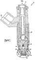
- FIGURE 1 is a sectional view of a nozzle which is made in accordance with the first preferred embodiment of the invention and which is operatively disposed within a vehicle fuel injector assembly.
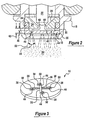
- FIGURE 2 is an enlarged sectional view of the region 2 which is illustrated in FIGURE 1 and illustrates the fuel injector assembly in an actuated position.
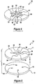
- FIGURE 3 is a perspective view of the nozzle shown in FIGURE 1.
- FIGURE 4 is a perspective view of a nozzle which is made in accordance with the second preferred embodiment of the present invention.
- FIGURE 5 is a perspective unassembled view of a nozzle which is formed in accordance with an alternate embodiment of the present invention.
- FIGURES 1-3 there is shown a nozzle, member, or plate 10 which is made in accordance with the teachings of the first preferred embodiment of the invention and which is adapted for use within a conventional vehicle fuel injector assembly 12. While the following discussion relates to the use of nozzle 10 in combination with a fuel injector assembly, it should be appreciated that in other alternate embodiments, nozzle 10 may be used with various other devices and assemblies in order to selectively discharge and finely atomize other types of pressurized fluid or material.
- Fuel injector assembly 12 includes a fuel intake port or conduit 14 that selectively receives liquid and/or vaporized fuel.
- a generally cylindrical channel 16 is formed within the valve body assembly 18 of the fuel injector 12, and communicates with port 14 to receive and channel fuel to nozzle 10.
- Fuel injector 12 further preferably includes a selectively actuatable valve, needle or member 22 which is movably disposed within the channel 18 and which selectively engages a valve seat 24.
- Member 22 is selectively movable from a first position in which member 22 engages the inner surface 23 of a valve seat or member 24, effective to prevent fuel from being discharged through nozzle 10, and a second position in which member 22 is distanced from seat 24 (e.g., as shown in FIGURE 2), effective to allow fuel to be discharged from nozzle 10.
- coil assembly 26 selectively actuates member 22 (e.g., causes member 22 to move in the directions of arrows 28, 30) in response to control signals received through terminal 32, which is communicatively coupled to an engine control module (not shown).
- Nozzle 10 is fixedly disposed (e.g., laser welded) within body assembly 18 and partially abuts seat 24. Particularly, nozzle 10 is disposed immediately below seat 24, and cooperates with seat 24 to channel and discharge fuel from injector 12.
- a conventional annular seal or o-ring 34 is disposed between the outer portion or periphery of nozzle 10 and the other portion or periphery of seat 24, and effective to prevent fuel from "leaking" from injector 12.
- a “back-up” washer 35 abuts nozzle 10 and holds nozzle 10 against seat 24.
- Nozzle 10 is preferably manufactured from a corrosive resistant material and includes several grooves, ports or channels 36 which are interconnected at the approximate center of nozzle 10.
- Nozzle 10 further comprises several "swirl" chambers 38, each of which is disposed at the end of channel 36 remote from the center of nozzle 10 and communicates with a unique one of channels 36.
- four such channels 36 and chambers 38 are formed within nozzle 10, and cooperate with the bottom surface 25 of seat 24 to form passages or conduits 46 through which fuel selectively flows (e.g., in the directions of arrows 48) prior to being discharged from nozzle 10.
- different numbers of channels 36 and chambers 38 may be formed within nozzle 10.
- a nozzle 60 includes six interconnected channels 62 and six chambers 64.
- channels 36 and chambers 38 each have a depth 40 which is equal to approximately half of the thickness 42 of nozzle 10.
- Each chamber 38 includes an aperture or discharge hole 44 which allows fuel within the chamber 38 to be discharged from nozzle 10.
- Each chamber 38 has a generally "helical" shape which, as described more fully and completely below, is effective to cause the fuel that is channeled into the chamber 38 to 'swirl" and/or spiral prior to being discharged from aperture 44.
- chambers 38 may have other shapes that are effective to cause fuel that is channeled into the chambers to "swirl" and/or spiral.
- ports 36, chambers 38 and holes 44 are formed within nozzle 10 by use of a conventional chemical etching, stamping or electroforming process.
- nozzle 10 is formed from two generally circular plates or members 11 and 13. Plate 11 includes channels 36 and swirl chambers 38 which are integrally formed within plate 11, and plate 13 includes discharge holes 44 which are integrally formed in plate 13.
- nozzle 10 is assembled by aligning chambers 38 with holes 44 and joining plates 11 and 13 in a conventional manner, such as by use of a conventional adhesive or a conventional bonding process.
- valve 22 In operation, when valve 22 is actuated or moved in the direction of arrow 28, pressurized fuel and/or vapor is channeled or directed away from the center of nozzle 10 through ports 36 in the direction of arrows 48 and into swirl chambers 38.
- Each chamber 38 receives the pressurized fuel and/or vapor and acts as a "swirl" or vortex generator causing rotational or angular motion (e.g., motion in the directions of arrows 50) to be imparted upon the pressurized fuel.
- the direction and pressure of the traveling fuel and the shape of chambers 38 causes the fuel to relatively rapidly swirl and/or spiral within the chambers 38.
- the rapidly swirling and/or spiraling fuel is then discharged through holes 44 as conical sheets 52 which combine and/or merge with each other and relatively quickly disintegrate into a finely atomized spray 54.
- discharge holes 44 are positioned within chambers 38 so as to correspond and/or be aligned with the center or "eye" of the vortexes or spirals generated within the chambers.
- the swirling and/or spiraling motion generated within chambers 38 and the multiple intermixing conical sheets 52 cause the discharged fuel to have improved atomization qualities relative to conventional nozzles.
- the discharged fuel is "disintegrated" or atomized faster and has a higher level of atomization relative to prior nozzles.
- the dimension of the ports or channels 36, swirl chambers 38, and discharge holes 44 may be designed and/or adjusted to achieve certain requirements regarding fuel flow rates, fuel droplet size distribution, and/or the angles 56 of conical sheets 52.
Landscapes
- Engineering & Computer Science (AREA)
- Chemical & Material Sciences (AREA)
- Combustion & Propulsion (AREA)
- Mechanical Engineering (AREA)
- General Engineering & Computer Science (AREA)
- Physics & Mathematics (AREA)
- Electromagnetism (AREA)
- Fuel-Injection Apparatus (AREA)
Abstract
Description
Claims (6)
- A nozzle for a fuel-injector comprising: a plurality of channels through which a pressurized material selectively flows, and a plurality of chambers each of which is disposed at an end of a unique one of said plurality of channels and is effective to receive the pressurized material and to swirl the received pressurized material, each of said plurality of chambers including an aperture which is effective to discharge the swirling pressurized material, thereby causing the pressurized material to form a finely atomized spray.
- The nozzle of Claim 1 wherein each of said plurality of chambers is generally helical in shape.
- The nozzle of Claim 1 further comprising a first plate in which said plurality of channels and said plurality of chambers are integrally formed and a second plate which is fixedly coupled to said first plate and in which said plurality of apertures are integrally formed.
- The nozzle of Claim 3 wherein said plurality of channels and said plurality of chambers are integrally formed in said first plate by use of a stamping process.
- The nozzle of Claim 3 wherein said plurality of channels and said plurality of chambers are integrally formed in said first plate by use of a chemical etching process.
- The nozzle of Claim 3 wherein said plurality of channels and said plurality of chambers are formed by use of an electroforming process.
Applications Claiming Priority (2)
| Application Number | Priority Date | Filing Date | Title |
|---|---|---|---|
| US656389 | 2000-09-06 | ||
| US09/656,389 US6405945B1 (en) | 2000-09-06 | 2000-09-06 | Nozzle for a fuel injector |
Publications (2)
| Publication Number | Publication Date |
|---|---|
| EP1186774A2 true EP1186774A2 (en) | 2002-03-13 |
| EP1186774A3 EP1186774A3 (en) | 2003-12-17 |
Family
ID=24632827
Family Applications (1)
| Application Number | Title | Priority Date | Filing Date |
|---|---|---|---|
| EP01121372A Withdrawn EP1186774A3 (en) | 2000-09-06 | 2001-09-06 | Nozzle for a fuel injector |
Country Status (3)
| Country | Link |
|---|---|
| US (1) | US6405945B1 (en) |
| EP (1) | EP1186774A3 (en) |
| JP (1) | JP2002098028A (en) |
Cited By (7)
| Publication number | Priority date | Publication date | Assignee | Title |
|---|---|---|---|---|
| GB2386157A (en) * | 2002-01-31 | 2003-09-10 | Visteon Global Tech Inc | Fuel injector nozzle plate with swirl chambers |
| FR2844833A1 (en) * | 2002-09-25 | 2004-03-26 | Siemens Vdo Automotive Corp | JET CONFIGURATION CONTROL WITH ANGULAR ORIENTATION IN A FUEL INJECTOR AND RELATED METHOD |
| WO2004041424A1 (en) * | 2002-11-06 | 2004-05-21 | Robert Bosch Gmbh | Dosing device |
| US20120102736A1 (en) * | 2009-09-02 | 2012-05-03 | Turbulent Energy Llc | Micro-injector and method of assembly and mounting thereof |
| CN103573504A (en) * | 2012-07-25 | 2014-02-12 | 日立汽车系统株式会社 | Fuel injection valve |
| US10626835B2 (en) | 2015-03-17 | 2020-04-21 | Enplas Corporation | Nozzle plate for fuel injection device |
| EP4170154A1 (en) * | 2021-10-21 | 2023-04-26 | Heinz Hänggi Stanztechnik | Atomizer disc and method of producing an atomizer disc |
Families Citing this family (46)
| Publication number | Priority date | Publication date | Assignee | Title |
|---|---|---|---|---|
| DE10041440A1 (en) * | 2000-08-23 | 2002-03-07 | Bosch Gmbh Robert | Swirl disk and fuel injector with swirl disk |
| EP1201917B1 (en) * | 2000-10-26 | 2005-10-26 | Hitachi, Ltd. | Fuel injection valve and fuel injection system |
| DE10055513B4 (en) * | 2000-11-09 | 2006-03-09 | Robert Bosch Gmbh | Fuel injector |
| US6513724B1 (en) * | 2001-06-13 | 2003-02-04 | Siemens Automotive Corporation | Method and apparatus for defining a spray pattern from a fuel injector |
| JP3784748B2 (en) * | 2002-05-17 | 2006-06-14 | 株式会社ケーヒン | Fuel injection valve |
| JP3715253B2 (en) * | 2002-05-17 | 2005-11-09 | 株式会社ケーヒン | Fuel injection valve |
| JP2003336561A (en) * | 2002-05-17 | 2003-11-28 | Keihin Corp | Fuel injection valve |
| DE10319694A1 (en) * | 2003-05-02 | 2004-12-02 | Robert Bosch Gmbh | Fuel injector |
| US7093776B2 (en) * | 2004-06-29 | 2006-08-22 | Delphi Technologies, Inc | Fuel injector nozzle atomizer having individual passages for inward directed accelerated cross-flow |
| WO2006025114A1 (en) * | 2004-09-01 | 2006-03-09 | Hitachi, Ltd. | Fuel injection valve |
| US7104475B2 (en) * | 2004-11-05 | 2006-09-12 | Visteon Global Technologies, Inc. | Low pressure fuel injector nozzle |
| US7124963B2 (en) * | 2004-11-05 | 2006-10-24 | Visteon Global Technologies, Inc. | Low pressure fuel injector nozzle |
| US7168637B2 (en) * | 2004-11-05 | 2007-01-30 | Visteon Global Technologies, Inc. | Low pressure fuel injector nozzle |
| US7051957B1 (en) * | 2004-11-05 | 2006-05-30 | Visteon Global Technologies, Inc. | Low pressure fuel injector nozzle |
| US7198207B2 (en) * | 2004-11-05 | 2007-04-03 | Visteon Global Technologies, Inc. | Low pressure fuel injector nozzle |
| US7438241B2 (en) * | 2004-11-05 | 2008-10-21 | Visteon Global Technologies, Inc. | Low pressure fuel injector nozzle |
| US7185831B2 (en) * | 2004-11-05 | 2007-03-06 | Ford Motor Company | Low pressure fuel injector nozzle |
| US7137577B2 (en) * | 2004-11-05 | 2006-11-21 | Visteon Global Technologies, Inc. | Low pressure fuel injector nozzle |
| JP4300197B2 (en) * | 2005-06-03 | 2009-07-22 | 株式会社日立製作所 | Fuel injection valve and internal combustion engine using the same |
| US7597275B2 (en) * | 2005-07-25 | 2009-10-06 | Isothermal Systems Research, Inc. | Methods and apparatus for atomization of a liquid |
| US7621739B2 (en) | 2005-07-25 | 2009-11-24 | Isothermal Systems Research, Inc. | Injection molding apparatus for producing an atomizer |
| JP4089915B2 (en) * | 2005-08-09 | 2008-05-28 | 三菱電機株式会社 | Fuel injection valve |
| US8500044B2 (en) * | 2007-05-04 | 2013-08-06 | S.C. Johnson & Son, Inc. | Multiple nozzle differential fluid delivery head |
| US7735756B2 (en) * | 2006-04-12 | 2010-06-15 | Combustion Components Associates, Inc. | Advanced mechanical atomization for oil burners |
| US8820664B2 (en) | 2007-05-16 | 2014-09-02 | S.C. Johnson & Son, Inc. | Multiple nozzle differential fluid delivery head |
| US9242256B2 (en) * | 2007-07-17 | 2016-01-26 | S.C. Johnson & Son, Inc. | Aerosol dispenser assembly having VOC-free propellant and dispensing mechanism therefor |
| DE102008042116B4 (en) * | 2008-09-15 | 2019-12-24 | Robert Bosch Gmbh | Valve for atomizing fluid |
| JP5253480B2 (en) * | 2010-11-01 | 2013-07-31 | 日立オートモティブシステムズ株式会社 | Fuel injection valve |
| JP5277264B2 (en) * | 2011-01-27 | 2013-08-28 | 日立オートモティブシステムズ株式会社 | Fuel injection valve |
| JP5492131B2 (en) * | 2011-03-31 | 2014-05-14 | 日立オートモティブシステムズ株式会社 | Fuel injection valve |
| DE102012211665A1 (en) * | 2011-08-18 | 2013-02-21 | Robert Bosch Gmbh | Valve for a flowing fluid |
| JP5961383B2 (en) | 2012-01-11 | 2016-08-02 | 日立オートモティブシステムズ株式会社 | Fuel injection valve |
| JP5852463B2 (en) * | 2012-02-14 | 2016-02-03 | 日立オートモティブシステムズ株式会社 | Fuel injection valve |
| JP5875443B2 (en) * | 2012-03-30 | 2016-03-02 | 日立オートモティブシステムズ株式会社 | Fuel injection valve |
| JP5875442B2 (en) * | 2012-03-30 | 2016-03-02 | 日立オートモティブシステムズ株式会社 | Fuel injection valve |
| JP5930903B2 (en) * | 2012-07-27 | 2016-06-08 | 日立オートモティブシステムズ株式会社 | Fuel injection valve |
| JP2014031757A (en) * | 2012-08-03 | 2014-02-20 | Hitachi Automotive Systems Ltd | Fuel injection valve |
| JP2014066175A (en) * | 2012-09-26 | 2014-04-17 | Hitachi Automotive Systems Ltd | Fuel injection valve |
| JP2016050552A (en) * | 2014-09-02 | 2016-04-11 | 日立オートモティブシステムズ株式会社 | Fuel injection valve |
| JP6346109B2 (en) * | 2015-03-11 | 2018-06-20 | 日立オートモティブシステムズ株式会社 | Fuel injection valve |
| CN108661836A (en) * | 2018-06-22 | 2018-10-16 | 广西卡迪亚科技有限公司 | A kind of fuel injector and its novel atomized structure big flow eddy flow composite structure |
| JP6609009B2 (en) * | 2018-08-02 | 2019-11-20 | 日立オートモティブシステムズ株式会社 | Fuel injection valve |
| JP6979993B2 (en) * | 2018-08-02 | 2021-12-15 | 日立Astemo株式会社 | Fuel injection valve |
| WO2020148821A1 (en) * | 2019-01-16 | 2020-07-23 | 三菱電機株式会社 | Fuel injection device |
| DE102020209855A1 (en) | 2020-08-05 | 2022-02-10 | Robert Bosch Gesellschaft mit beschränkter Haftung | Injector for injecting a fluid and manufacturing method for such an injector |
| CN115013204A (en) * | 2022-06-20 | 2022-09-06 | 江苏大学 | Dual-fuel vortex nozzle |
Family Cites Families (10)
| Publication number | Priority date | Publication date | Assignee | Title |
|---|---|---|---|---|
| US4313568A (en) * | 1980-05-27 | 1982-02-02 | Ethyl Products Company | Fluid dispenser method and apparatus |
| US4793913A (en) * | 1983-02-04 | 1988-12-27 | Chevron Research Company | Method for liquid feed dispersion in fluid catalytic cracking systems |
| US5435884A (en) | 1993-09-30 | 1995-07-25 | Parker-Hannifin Corporation | Spray nozzle and method of manufacturing same |
| US5685491A (en) * | 1995-01-11 | 1997-11-11 | Amtx, Inc. | Electroformed multilayer spray director and a process for the preparation thereof |
| AUPO080496A0 (en) * | 1996-07-03 | 1996-07-25 | Exell Trading Pty Limited | Nozzle assembly for a spray head |
| US5826798A (en) * | 1996-10-01 | 1998-10-27 | Todd Combustion | Atomizer with array of discharge holes to provide improved combustion efficiency and process |
| US5860602A (en) * | 1996-12-06 | 1999-01-19 | Tilton; Charles L | Laminated array of pressure swirl atomizers |
| DE19703200A1 (en) * | 1997-01-30 | 1998-08-06 | Bosch Gmbh Robert | Fuel injector |
| US6065692A (en) * | 1999-06-09 | 2000-05-23 | Siemens Automotive Corporation | Valve seat subassembly for fuel injector |
| US6513724B1 (en) * | 2001-06-13 | 2003-02-04 | Siemens Automotive Corporation | Method and apparatus for defining a spray pattern from a fuel injector |
-
2000
- 2000-09-06 US US09/656,389 patent/US6405945B1/en not_active Expired - Lifetime
-
2001
- 2001-09-04 JP JP2001267264A patent/JP2002098028A/en active Pending
- 2001-09-06 EP EP01121372A patent/EP1186774A3/en not_active Withdrawn
Cited By (10)
| Publication number | Priority date | Publication date | Assignee | Title |
|---|---|---|---|---|
| GB2386157A (en) * | 2002-01-31 | 2003-09-10 | Visteon Global Tech Inc | Fuel injector nozzle plate with swirl chambers |
| US6783085B2 (en) | 2002-01-31 | 2004-08-31 | Visteon Global Technologies, Inc. | Fuel injector swirl nozzle assembly |
| GB2386157B (en) * | 2002-01-31 | 2005-05-11 | Visteon Global Tech Inc | Fuel injector swirl nozzle assembly |
| FR2844833A1 (en) * | 2002-09-25 | 2004-03-26 | Siemens Vdo Automotive Corp | JET CONFIGURATION CONTROL WITH ANGULAR ORIENTATION IN A FUEL INJECTOR AND RELATED METHOD |
| WO2004041424A1 (en) * | 2002-11-06 | 2004-05-21 | Robert Bosch Gmbh | Dosing device |
| US20120102736A1 (en) * | 2009-09-02 | 2012-05-03 | Turbulent Energy Llc | Micro-injector and method of assembly and mounting thereof |
| CN103573504A (en) * | 2012-07-25 | 2014-02-12 | 日立汽车系统株式会社 | Fuel injection valve |
| US10626835B2 (en) | 2015-03-17 | 2020-04-21 | Enplas Corporation | Nozzle plate for fuel injection device |
| EP4170154A1 (en) * | 2021-10-21 | 2023-04-26 | Heinz Hänggi Stanztechnik | Atomizer disc and method of producing an atomizer disc |
| WO2023066530A1 (en) * | 2021-10-21 | 2023-04-27 | Heinz Hänggi Stanztechnik | Atomiser disc and method for producing an atomiser disc |
Also Published As
| Publication number | Publication date |
|---|---|
| US6405945B1 (en) | 2002-06-18 |
| JP2002098028A (en) | 2002-04-05 |
| EP1186774A3 (en) | 2003-12-17 |
Similar Documents
| Publication | Publication Date | Title |
|---|---|---|
| US6405945B1 (en) | Nozzle for a fuel injector | |
| JP2996525B2 (en) | Fuel injection valve | |
| US6161780A (en) | Fuel injection valve for an internal combustion engine | |
| EP1157207B1 (en) | Fuel injector with turbulence generator for fuel orifice | |
| US4149496A (en) | Throttle body injection apparatus | |
| JP4024144B2 (en) | Fuel injection device | |
| US7104475B2 (en) | Low pressure fuel injector nozzle | |
| WO1999032784A1 (en) | Flat needle for pressurized swirl fuel injector | |
| US7124963B2 (en) | Low pressure fuel injector nozzle | |
| KR100420748B1 (en) | Fuel injection valve | |
| JPH09510530A (en) | Multi-disc air-assisted atomizer for fuel injectors | |
| WO2008005484A1 (en) | Fuel injection system with cross-flow nozzle for enhanced compressed natural gas jet spray | |
| US20100051724A1 (en) | Dual Action Fuel Injection Nozzle | |
| US20090200403A1 (en) | Fuel injector | |
| US7438241B2 (en) | Low pressure fuel injector nozzle | |
| US7051957B1 (en) | Low pressure fuel injector nozzle | |
| US7137577B2 (en) | Low pressure fuel injector nozzle | |
| US7198207B2 (en) | Low pressure fuel injector nozzle | |
| US6422198B1 (en) | Pressure atomizer having multiple orifices and turbulent generation feature | |
| JP3517927B2 (en) | Fluid injection nozzle | |
| US6371387B1 (en) | Air assist metering apparatus and method | |
| US20120223164A1 (en) | Nozzle assembly for an injection valve and injection valve | |
| US6877678B2 (en) | Fuel injector flow director plate retainer | |
| US12416280B2 (en) | High-pressure fuel injection system | |
| KR0126296Y1 (en) | Fuel secondary atomizer of the internal combustion engine |
Legal Events
| Date | Code | Title | Description |
|---|---|---|---|
| PUAI | Public reference made under article 153(3) epc to a published international application that has entered the european phase |
Free format text: ORIGINAL CODE: 0009012 |
|
| AK | Designated contracting states |
Kind code of ref document: A2 Designated state(s): AT BE CH CY DE DK ES FI FR GB GR IE IT LI LU MC NL PT SE TR |
|
| AX | Request for extension of the european patent |
Free format text: AL;LT;LV;MK;RO;SI |
|
| 17P | Request for examination filed |
Effective date: 20020910 |
|
| PUAL | Search report despatched |
Free format text: ORIGINAL CODE: 0009013 |
|
| AK | Designated contracting states |
Kind code of ref document: A3 Designated state(s): AT BE CH CY DE DK ES FI FR GB GR IE IT LI LU MC NL PT SE TR |
|
| AX | Request for extension of the european patent |
Extension state: AL LT LV MK RO SI |
|
| RIC1 | Information provided on ipc code assigned before grant |
Ipc: 7B 05B 1/34 B Ipc: 7F 02M 61/16 B Ipc: 7F 02M 61/18 B Ipc: 7F 02M 51/06 A |
|
| 17Q | First examination report despatched |
Effective date: 20040122 |
|
| AKX | Designation fees paid |
Designated state(s): DE FR GB |
|
| STAA | Information on the status of an ep patent application or granted ep patent |
Free format text: STATUS: THE APPLICATION IS DEEMED TO BE WITHDRAWN |
|
| 18D | Application deemed to be withdrawn |
Effective date: 20040602 |