EP1186773A2 - Fuel injector - Google Patents
Fuel injector Download PDFInfo
- Publication number
- EP1186773A2 EP1186773A2 EP01121254A EP01121254A EP1186773A2 EP 1186773 A2 EP1186773 A2 EP 1186773A2 EP 01121254 A EP01121254 A EP 01121254A EP 01121254 A EP01121254 A EP 01121254A EP 1186773 A2 EP1186773 A2 EP 1186773A2
- Authority
- EP
- European Patent Office
- Prior art keywords
- pressure control
- fuel
- displaced
- needle
- displacement
- Prior art date
- Legal status (The legal status is an assumption and is not a legal conclusion. Google has not performed a legal analysis and makes no representation as to the accuracy of the status listed.)
- Granted
Links
- 239000000446 fuel Substances 0.000 title claims abstract description 174
- 238000006073 displacement reaction Methods 0.000 claims abstract description 96
- 238000002347 injection Methods 0.000 claims description 65
- 239000007924 injection Substances 0.000 claims description 65
- 238000007599 discharging Methods 0.000 claims description 19
- 238000002485 combustion reaction Methods 0.000 description 5
- 239000000203 mixture Substances 0.000 description 2
- 230000035515 penetration Effects 0.000 description 2
- 239000003054 catalyst Substances 0.000 description 1
- 239000003638 chemical reducing agent Substances 0.000 description 1
- 230000006835 compression Effects 0.000 description 1
- 238000007906 compression Methods 0.000 description 1
- 230000003628 erosive effect Effects 0.000 description 1
- 239000002828 fuel tank Substances 0.000 description 1
- ZZUFCTLCJUWOSV-UHFFFAOYSA-N furosemide Chemical compound C1=C(Cl)C(S(=O)(=O)N)=CC(C(O)=O)=C1NCC1=CC=CO1 ZZUFCTLCJUWOSV-UHFFFAOYSA-N 0.000 description 1
- 239000000779 smoke Substances 0.000 description 1
Images






Classifications
-
- F—MECHANICAL ENGINEERING; LIGHTING; HEATING; WEAPONS; BLASTING
- F02—COMBUSTION ENGINES; HOT-GAS OR COMBUSTION-PRODUCT ENGINE PLANTS
- F02M—SUPPLYING COMBUSTION ENGINES IN GENERAL WITH COMBUSTIBLE MIXTURES OR CONSTITUENTS THEREOF
- F02M47/00—Fuel-injection apparatus operated cyclically with fuel-injection valves actuated by fluid pressure
- F02M47/02—Fuel-injection apparatus operated cyclically with fuel-injection valves actuated by fluid pressure of accumulator-injector type, i.e. having fuel pressure of accumulator tending to open, and fuel pressure in other chamber tending to close, injection valves and having means for periodically releasing that closing pressure
- F02M47/027—Electrically actuated valves draining the chamber to release the closing pressure
-
- F—MECHANICAL ENGINEERING; LIGHTING; HEATING; WEAPONS; BLASTING
- F02—COMBUSTION ENGINES; HOT-GAS OR COMBUSTION-PRODUCT ENGINE PLANTS
- F02M—SUPPLYING COMBUSTION ENGINES IN GENERAL WITH COMBUSTIBLE MIXTURES OR CONSTITUENTS THEREOF
- F02M45/00—Fuel-injection apparatus characterised by having a cyclic delivery of specific time/pressure or time/quantity relationship
- F02M45/12—Fuel-injection apparatus characterised by having a cyclic delivery of specific time/pressure or time/quantity relationship providing a continuous cyclic delivery with variable pressure
-
- F—MECHANICAL ENGINEERING; LIGHTING; HEATING; WEAPONS; BLASTING
- F02—COMBUSTION ENGINES; HOT-GAS OR COMBUSTION-PRODUCT ENGINE PLANTS
- F02M—SUPPLYING COMBUSTION ENGINES IN GENERAL WITH COMBUSTIBLE MIXTURES OR CONSTITUENTS THEREOF
- F02M63/00—Other fuel-injection apparatus having pertinent characteristics not provided for in groups F02M39/00 - F02M57/00 or F02M67/00; Details, component parts, or accessories of fuel-injection apparatus, not provided for in, or of interest apart from, the apparatus of groups F02M39/00 - F02M61/00 or F02M67/00; Combination of fuel pump with other devices, e.g. lubricating oil pump
- F02M63/0012—Valves
- F02M63/0014—Valves characterised by the valve actuating means
- F02M63/0015—Valves characterised by the valve actuating means electrical, e.g. using solenoid
- F02M63/0026—Valves characterised by the valve actuating means electrical, e.g. using solenoid using piezoelectric or magnetostrictive actuators
-
- F—MECHANICAL ENGINEERING; LIGHTING; HEATING; WEAPONS; BLASTING
- F02—COMBUSTION ENGINES; HOT-GAS OR COMBUSTION-PRODUCT ENGINE PLANTS
- F02M—SUPPLYING COMBUSTION ENGINES IN GENERAL WITH COMBUSTIBLE MIXTURES OR CONSTITUENTS THEREOF
- F02M63/00—Other fuel-injection apparatus having pertinent characteristics not provided for in groups F02M39/00 - F02M57/00 or F02M67/00; Details, component parts, or accessories of fuel-injection apparatus, not provided for in, or of interest apart from, the apparatus of groups F02M39/00 - F02M61/00 or F02M67/00; Combination of fuel pump with other devices, e.g. lubricating oil pump
- F02M63/0012—Valves
- F02M63/0031—Valves characterized by the type of valves, e.g. special valve member details, valve seat details, valve housing details
- F02M63/0033—Lift valves, i.e. having a valve member that moves perpendicularly to the plane of the valve seat
- F02M63/0036—Lift valves, i.e. having a valve member that moves perpendicularly to the plane of the valve seat with spherical or partly spherical shaped valve member ends
-
- F—MECHANICAL ENGINEERING; LIGHTING; HEATING; WEAPONS; BLASTING
- F02—COMBUSTION ENGINES; HOT-GAS OR COMBUSTION-PRODUCT ENGINE PLANTS
- F02M—SUPPLYING COMBUSTION ENGINES IN GENERAL WITH COMBUSTIBLE MIXTURES OR CONSTITUENTS THEREOF
- F02M63/00—Other fuel-injection apparatus having pertinent characteristics not provided for in groups F02M39/00 - F02M57/00 or F02M67/00; Details, component parts, or accessories of fuel-injection apparatus, not provided for in, or of interest apart from, the apparatus of groups F02M39/00 - F02M61/00 or F02M67/00; Combination of fuel pump with other devices, e.g. lubricating oil pump
- F02M63/0012—Valves
- F02M63/0031—Valves characterized by the type of valves, e.g. special valve member details, valve seat details, valve housing details
- F02M63/004—Sliding valves, e.g. spool valves, i.e. whereby the closing member has a sliding movement along a seat for opening and closing
-
- F—MECHANICAL ENGINEERING; LIGHTING; HEATING; WEAPONS; BLASTING
- F02—COMBUSTION ENGINES; HOT-GAS OR COMBUSTION-PRODUCT ENGINE PLANTS
- F02M—SUPPLYING COMBUSTION ENGINES IN GENERAL WITH COMBUSTIBLE MIXTURES OR CONSTITUENTS THEREOF
- F02M63/00—Other fuel-injection apparatus having pertinent characteristics not provided for in groups F02M39/00 - F02M57/00 or F02M67/00; Details, component parts, or accessories of fuel-injection apparatus, not provided for in, or of interest apart from, the apparatus of groups F02M39/00 - F02M61/00 or F02M67/00; Combination of fuel pump with other devices, e.g. lubricating oil pump
- F02M63/0012—Valves
- F02M63/0031—Valves characterized by the type of valves, e.g. special valve member details, valve seat details, valve housing details
- F02M63/0045—Three-way valves
-
- F—MECHANICAL ENGINEERING; LIGHTING; HEATING; WEAPONS; BLASTING
- F02—COMBUSTION ENGINES; HOT-GAS OR COMBUSTION-PRODUCT ENGINE PLANTS
- F02M—SUPPLYING COMBUSTION ENGINES IN GENERAL WITH COMBUSTIBLE MIXTURES OR CONSTITUENTS THEREOF
- F02M63/00—Other fuel-injection apparatus having pertinent characteristics not provided for in groups F02M39/00 - F02M57/00 or F02M67/00; Details, component parts, or accessories of fuel-injection apparatus, not provided for in, or of interest apart from, the apparatus of groups F02M39/00 - F02M61/00 or F02M67/00; Combination of fuel pump with other devices, e.g. lubricating oil pump
- F02M63/0012—Valves
- F02M63/0031—Valves characterized by the type of valves, e.g. special valve member details, valve seat details, valve housing details
- F02M63/0056—Throttling valves, e.g. having variable opening positions throttling the flow
-
- F—MECHANICAL ENGINEERING; LIGHTING; HEATING; WEAPONS; BLASTING
- F02—COMBUSTION ENGINES; HOT-GAS OR COMBUSTION-PRODUCT ENGINE PLANTS
- F02M—SUPPLYING COMBUSTION ENGINES IN GENERAL WITH COMBUSTIBLE MIXTURES OR CONSTITUENTS THEREOF
- F02M63/00—Other fuel-injection apparatus having pertinent characteristics not provided for in groups F02M39/00 - F02M57/00 or F02M67/00; Details, component parts, or accessories of fuel-injection apparatus, not provided for in, or of interest apart from, the apparatus of groups F02M39/00 - F02M61/00 or F02M67/00; Combination of fuel pump with other devices, e.g. lubricating oil pump
- F02M63/0012—Valves
- F02M63/0059—Arrangements of valve actuators
- F02M63/0068—Actuators specially adapted for partial and full opening of the valves
Definitions
- the present invention relates to a fuel injector.
- Japanese Unexamined Patent Publication No. 8-334072 discloses a fuel injector having a housing with a nozzle, a needle movably accommodated in a needle accommodating chamber formed in the housing, and a control valve for controlling a displacement of the needle.
- the control valve is displaced by the pressure applied to the fuel injector, and is displaced to a zero-displaced position when the fuel pressure is low, to a fully-displaced position when the fuel pressure is high, and to an intermediate position between the zero displaced and the fully-displaced positions when the fuel pressure is medium.
- the needle can displace fully when the control valve is displaced to the zero-displaced position or a fully-displaced position, and can displace partly when the control valve is displaced to the intermediate position.
- control valve In the displacement of the control valve from the zero-displaced position to the fully-displaced position, the control valve must pass the intermediate position in which the displacement of the needle is limited. This may prevent a rapid displacement of the needle to open the nozzle fully.
- An object of the invention is to provide a fuel injector which is capable of rapidly displacing the needle.
- a fuel injector comprising: a housing with a nozzle; a needle movably accommodated in a needle accommodating chamber formed in the housing, for opening or closing the nozzle; a pressure control chamber defined between the needle and an inner wall of the needle accommodating chamber and filled with a fuel, a displacement of the needle depending on the fuel pressure in the pressure control chamber; a pressure control valve movably provided in the housing for controlling the fuel pressure in the pressure control chamber; and an actuator for controlling a displacement of the pressure control valve; wherein the needle is displaced by a first displacement when the pressure control valve is displaced to the zero-displaced position, wherein the needle is displaced by a second displacement when the pressure control valve is displaced to the fully-displaced position, wherein the needle is displaced by a third displacement when the pressure control valve is displaced to an intermediate position between the zero-displaced position and the fully-displaced position, and wherein the third displacement is between the first and second displacements.
- a fuel injector 1 comprises a housing 2 and a needle 3.
- the housing 2 includes a nozzle holder 2a with a pair of nozzles 4, a casing body 2b, a actuator casing 2c, and chamber defining members 2d, 2e, 2f, 2g, and 2h.
- the needle 3 includes a needle body 3a and a plurality of piston members 3b, and is accommodated in a needle accommodating chamber 5 formed in the housing 2, movably along its longitudinal axis. The needle 3 is displaced to open or close the nozzles 4.
- a fuel supply conduit 6 is formed in the housing 2 from a fuel inlet 7 formed in the housing 2 to the nozzles 4.
- the fuel inlet 7 is connected to a high pressure fuel source such as a common rail (not shown) with a constant fuel pressure.
- a pressure control chamber 8 is defined between the top end of the needle 3 and an inner wall of the needle accommodating chamber 5.
- a displacement control piston 9 is axially and movably accommodated to divide the pressure control chamber 8 into first and second pressure control chambers 8a and 8b.
- the first pressure control chamber 8a is defined between the bottom end of the displacement control piston 9 and the top end of the needle 3
- the second pressure control chamber 8b is defined between the top end of the displacement control piston 9 and the inner wall of the needle accommodating chamber 5.
- the displacement control piston 9 includes an annular shoulder 9a, which limits a downward displacement of the piston 9 together with an annular shoulder 5a formed in the needle accommodating chamber 5. Note that an upward displacement of the piston 9 is limited by contact between the top end of the piston 9 and the top end wall of the needle accommodating chamber 5.
- a valve chamber 10 is also formed in the housing 2, which is connected to the pressure control chamber 8 via a discharging conduit. Specifically, the valve chamber 10 is connected to the first pressure control chamber 8a via a first discharging conduit 11a, and is connected to the second pressure control chamber 8b via a second discharging conduit 11b.
- the pressure control chambers 8a and 8b and the valve chamber 10 are filled with fuel.
- Relief conduits 12, formed in the housing 2 extend from the valve chamber 10 to a fuel outlet 13 formed in the housing 2.
- the fuel outlet 13 may be connected to a fuel tank (not shown).
- a pressure control valve 14 is movably accommodated in the valve chamber 10 along its longitudinal axis.
- the pressure control valve 14 includes a ball-shaped member 14a and a rod-shaped member 14b, integral with each other.
- the pressure control valve 14 is driven by an actuator 15, of a piezo-electronic type, accommodated in the housing 2.
- the actuator 15 controls an axial displacement of the pressure control valve 14 though a control of a fuel pressure in a fuel-filled chamber 16 between the actuator 15 and the pressure control valve 14.
- a fuel pressure in the chamber 16 increases, and thus the pressure control valve 14 displaces downwardly.
- the actuator shrinks along its longitudinal axis a fuel pressure in the chamber 16 drops, and thus the pressure control valve 14 displaces upwardly.
- the fuel supply conduit 6 includes a fuel collecting chamber 17, formed therein, in which a pressure receiving surface 3c, formed on the needle, is arranged. Accordingly, the needle 3 is urged by the fuel pressure, in the fuel collecting chamber 17, in a direction in which the needle 3 opens the nozzles 4. The needle 3 is also urged by a compressed spring 18, arranged between the needle 3 and the inner wall of the needle accommodating chamber 5, in a direction in which the needle 3 closes the nozzles 4.
- a high fuel pressure conduit 19 branches off from the fuel supply conduit 6, and is connected to the first and the second pressure control chambers 8a and 8b via first and second inflowing conduit 20a and 20b, respectively.
- the high fuel pressure conduit 19 is also connected to the valve chamber 10 via a third inflowing conduit 20c.
- first and second discharging conduits 11a and 11b, and the first, second, and third inflowing conduits 20a, 20b, 20c include chokes formed therein.
- the flow resistance of the second inflowing conduit 20b is set smaller than that of the first inflowing conduit 20a, and the flow resistance of the second discharging conduit 11b is set larger than that of the first discharging conduit 11a.
- a hydro erosive grinding is applied only in a direction from the valve chamber 10 to the pressure control chamber 8b, so that a discharge coefficient of the second discharging conduit 11b in a direction from the second pressure control chamber 8b to the valve chamber 10 is set smaller than that in a direction from the valve chamber 10 to the pressure control chamber 8b. Therefore, the pressure in the second pressure control chamber 8b is easily increased but difficult to reduce, with respect to the pressure in the first pressure control chamber 8a.
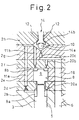
- Fig. 2 shows the case where the pressure control valve 14 is in a zero-displaced position. In this position, the pressure control valve 14 prevents communication between the valve chamber 10 and the relief conduits 12, and connects the valve chamber 10 with the high fuel pressure conduit 19. In this condition, fuel in the high fuel pressure conduit 19 flows into the first pressure control chamber 8a, via the first inflowing conduit 20a, and via the third inflowing conduit 20c, the valve chamber 10, and the first discharging conduit 11a. Also, fuel flows into the second pressure control chamber 8b via the second inflowing conduit 20b, and via the third inflowing conduit 20c, the valve chamber 10, and the second discharging conduit 11b.
- the top of the needle 3 and the bottom of the displacement control piston 9 are spaced apart from each other by a distance D1
- the top of the piston 9 and the top of the inner wall of the needle accommodating chamber 5 are spaced apart from each other by a distance D2, as shown in Fig. 3.
- Fig. 4 shows the case where the pressure control valve 14 is in an intermediate position or is displaced by a small displacement SD from the zero-displacement position.
- the pressure control valve 14 partly connects the valve chamber 10 with the relief conduits 12, and connects the valve chamber 10 with the high fuel pressure conduit 19.
- fuel flows into the first pressure control chamber 8a via the first inflowing conduit 20a.
- fuel in the first pressure control chamber 8a flows out therefrom via the first discharging conduit 11a and the valve chamber 10 to the relief conduits 12. Therefore, the pressure in the first pressure control chamber 8a drops.
- the upward force acting on the needle 3 exceeds the downward force acting on the needle 3, and thus the needle 3 is displaced upwardly.
- the upward displacement of the needle 3 is limited by an abutment of the needle 3 with the displacement control piston 9, as shown in Fig. 5. In this way, the needle 3 is displaced by the displacement D1 or partly opens the nozzles 4, by the small displacement of the pressure control valve 14.
- Fig. 5 shows the case where the pressure control valve 14 is in a fully-displaced position or is displaced by a full displacement FD from the zero-displacement position. In this position, the pressure control valve 14 connects the valve chamber 10 with the relief conduits 12, and prevents communication between the valve chamber 10 and the high fuel pressure conduit 19. In this condition, the pressure in the first pressure control chamber 8a is kept low because fuel in the first pressure control chamber 8a flows out therefrom via the first discharging conduit 11a and the valve chamber 10 to the relief conduits 12.
- the displacement control piston 9 is displaced upwardly until it contacts with the inner wall of the needle accommodating chamber 5, and is kept its uppermost position.
- the needle 3 is also displaced upwardly until it contacts with the displacement control piston 9. Therefore, the needle 3 is displaced by the displacement D2 from the condition shown in Fig. 4 or fully opens the nozzles 4, by the full displacement of the pressure control valve 14.
- Figs. 6 to 11 shows various embodiments of the fuel injection.
- the displacement VD of the pressure control valve 14 is made equal to and is temporarily kept at the small displacement SD, and then is made equal to and is temporarily kept at the full displacement FD. Then, the valve displacement VD is returned to zero.
- the needle displacement ND is first made equal to and is temporarily kept at the displacement D1, and thus the fuel injection with a fuel injection rate FIR being a low rate RL is performed.
- the needle displacement ND is then increased to D1 + D2, and thus the fuel injection with the fuel injection rate FIR being a high rate RH is performed.
- the fuel injection shown in Fig. 6 is started with the low injection rate RL, and therefore, a generation of NO x , and the combustion noise, are suppressed.
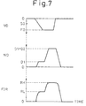
- valve displacement VD is continuously increased from the zero-displaced position to the fully-displaced position, and kept at the full displacement FD for a preset time. Then, the valve displacement VD is returned to zero.
- a displacing rate of the pressure control valve 14 is set so that the needle displacement ND is first made equal to and is temporarily kept at the displacement D1 and then the needle displacement ND is increased to D1 + D2, as in the embodiment shown in Fig. 6.
- the fuel injection with a fuel injection rate FIR being the low rate RL is first performed, and then the fuel injection with the fuel injection rate FIR being the high rate RH is performed.
- the pressure in the second pressure control chamber 8b is easily increased but is difficult to reduce, with respect to the pressure in the first pressure control chamber 8a. Therefore, even if the valve displacement VD is smaller than the small displacement SD, the needle 3 starts displacing upwardly when the upward force acting on the needle 3 exceeds the downward force acting on the needle 3. Further, even if the valve displacement VD is larger than the small displacement SD, the needle displacement ND is kept at the displacement D1 as long as the displacement control piston 9 is kept at its lowermost position. This means that no precise control of the displacement of the pressure control valve 14 is necessary in order to displace the needle 3 by the displacement D1.
- Fig. 8 shows a low-rate fuel injection in which the displacement VD of the pressure control valve 14 is made equal to, and is temporarily kept at, the small displacement SD, and then is returned to zero.
- the needle displacement ND is made equal to, and is temporarily kept at, the displacement D1
- the fuel injection with the low rate RL is performed.
- the low-rate injection provides a fuel jet having a low penetration force.
- valve displacement VD may be temporarily kept at a displacement larger than the small displacement SD, and then, may be temporarily kept at the small displacement SD, when the low-rate fuel injection should be performed. This promotes a rapid displacement of the needle 3 to open the nozzles 4.
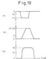
- Fig. 10 shows a high-rate fuel injection in which the displacement VD of the pressure control valve 14 is made equal to, and is temporarily kept at, the full displacement FD, and then is returned to zero.
- the needle displacement ND is made equal to, and is temporarily kept at, the displacement D1 + D2, and the fuel injection with the high rate RH is performed.
- the high-rate injection provides a jet of fuel having a high penetration force.
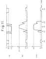
- Fig. 11 shows an embodiment of fuel injections performed in one combustion cycle of an engine, including a main fuel injection and additional fuel injections which is performed in addition to the main fuel injection.
- the main fuel injection M in the form of the high-rate injection may be performed around the top dead center of the intake stroke of the engine.
- a first additional injection A1 in the form of the low-rate injection is performed in the intake stroke, and a second additional injection A2 in the form of the high-rate injection is then performed at the end of the compression stroke.
- the first additional injection A1 in the form of the low-rate injection serves to form an air-fuel mixture spreading over the combustion chamber while preventing an adhesion of the additional fuel on the cylinder wall.
- the second additional injection A2 in the form of the high-rate injection serves to position the additional fuel near the fuel injected by the main fuel injection M, to thereby suppress generation of smoke.
- a third additional injection A3 in the form of the high-rate injection is performed at the top of the power stroke, and a fourth additional injection A4 in the form of the low-rate injection is then performed in the power or exhaust stroke.
- the third additional injection A3 in the form of the high-rate injection serves to enhance mixing of an air-fuel mixture in the combustion chamber.
- the fourth additional injection A4 in the form of the low-rate injection serves to feed a reducing agent to a catalyst provided in the exhaust passage for reducing NO x while preventing an adhesion of the additional fuel on the cylinder wall.
- Fig. 12 shows another embodiment of the fuel injection, in which the first inflowing conduit 20a is omitted. In this case, the fuel flows into the first pressure control chamber 8a via the first discharging conduit 11a.
- the needle displacement increases when the valve displacement increases.
- the pressure control valve 14 displaces from the zero-displaced position to the fully-displaced position, it is prevented that the nozzle is first displaced to its fully-displaced position and then its intermediate position. Therefore, a rapid displacement of the needle 3 is ensured.
- the actuator 15 is connected to the pressure control valve 14 via the fuel-filled chamber 16, and therefore, no precise control of a displacement of the actuator 15 is necessary. Even if the actuator 15 undesirably extends or shrinks according to its temperature, an undesirable change of the pressures in the first and second pressure control chambers 8a and 8b is prevented.
- the fuel is fed to the fuel injector 1 at a constant fuel pressure.
- the pressure of fuel supplied to the fuel injector 1 may vary according to the engine operating condition. In this case, if the fuel pressure becomes high, an amount of the actually injected fuel becomes large and, if the fuel pressure becomes low, the amount of the actually injected fuel becomes small.
- the low-rate injection may be performed when the fuel pressure is higher than an upper threshold, and the high-rate injection is performed when the fuel pressure is lower than a lower threshold. This avoids an excess or a lack of fuel fed to the engine. Further, when the fuel pressure is high, it is unnecessary to discharge a part of fuel in the fuel injector 1 therefrom to reduce the amount of the actually injected fuel.
- a pressure sensor may be provided in the common rail. Alternatively, it may be judged on the basis of the engine operating condition. Specifically, the fuel pressure will become high during a rapid deceleration just after a heavy-load operation of the engine.
- the needle 3 closes the nozzles 4 when the pressure control valve 14 is in the zero-displaced position, partly opens the nozzles 4 when the valve 14 is in the intermediate position, and fully opens the nozzles 4 when the valve 14 is in the fully-displaced position.
- the needle 3 closes the nozzles 4 when the valve 14 is in the fully-displaced position, partly opens the nozzles 4 when the valve 14 is in the intermediate position, and fully opens the nozzles 4 when the valve 14 is in the zero-displaced position.
- the embodiments described above include the displacement control piston 9 arranged in the pressure control chamber 8.
- the piston 9 may be omitted to provide a single pressure control chamber, a single inflowing conduit, and a single discharging conduit.
- a fuel injector comprising a housing with a nozzle, a needle movably accommodated in a needle accommodating chamber formed in the housing, for opening or closing the nozzle, a pressure control chamber defined between the needle and an inner wall of the needle accommodating chamber and filled with a fuel, a displacement of the needle depending on the fuel pressure in the pressure control chamber, a pressure control valve movably provided in the housing for controlling the fuel pressure in the pressure control chamber; and an actuator for controlling a displacement of the pressure control valve.
- the needle is displaced to a position in which it closes the nozzle when the pressure control valve is displaced to the zero-displaced position, is displaced to a position in which it partly opens the nozzle when the pressure control valve is displaced to an intermediate position, and is displaced to a position in which it fully opens the nozzle when the pressure control valve is displaced to a fully-displaced position.
Landscapes
- Engineering & Computer Science (AREA)
- Chemical & Material Sciences (AREA)
- Combustion & Propulsion (AREA)
- Mechanical Engineering (AREA)
- General Engineering & Computer Science (AREA)
- Physics & Mathematics (AREA)
- Fluid Mechanics (AREA)
- Fuel-Injection Apparatus (AREA)
Abstract
Description
- The present invention relates to a fuel injector.
- Japanese Unexamined Patent Publication No. 8-334072 discloses a fuel injector having a housing with a nozzle, a needle movably accommodated in a needle accommodating chamber formed in the housing, and a control valve for controlling a displacement of the needle. In this fuel injector, the control valve is displaced by the pressure applied to the fuel injector, and is displaced to a zero-displaced position when the fuel pressure is low, to a fully-displaced position when the fuel pressure is high, and to an intermediate position between the zero displaced and the fully-displaced positions when the fuel pressure is medium.
- The needle can displace fully when the control valve is displaced to the zero-displaced position or a fully-displaced position, and can displace partly when the control valve is displaced to the intermediate position.
- However, during the displacement of the control valve from the zero-displaced position to the fully-displaced position, the control valve must pass the intermediate position in which the displacement of the needle is limited. This may prevent a rapid displacement of the needle to open the nozzle fully.
- An object of the invention is to provide a fuel injector which is capable of rapidly displacing the needle.
- According to the present invention, there is provided a fuel injector comprising: a housing with a nozzle; a needle movably accommodated in a needle accommodating chamber formed in the housing, for opening or closing the nozzle; a pressure control chamber defined between the needle and an inner wall of the needle accommodating chamber and filled with a fuel, a displacement of the needle depending on the fuel pressure in the pressure control chamber; a pressure control valve movably provided in the housing for controlling the fuel pressure in the pressure control chamber; and an actuator for controlling a displacement of the pressure control valve; wherein the needle is displaced by a first displacement when the pressure control valve is displaced to the zero-displaced position, wherein the needle is displaced by a second displacement when the pressure control valve is displaced to the fully-displaced position, wherein the needle is displaced by a third displacement when the pressure control valve is displaced to an intermediate position between the zero-displaced position and the fully-displaced position, and wherein the third displacement is between the first and second displacements.
- In the drawings:
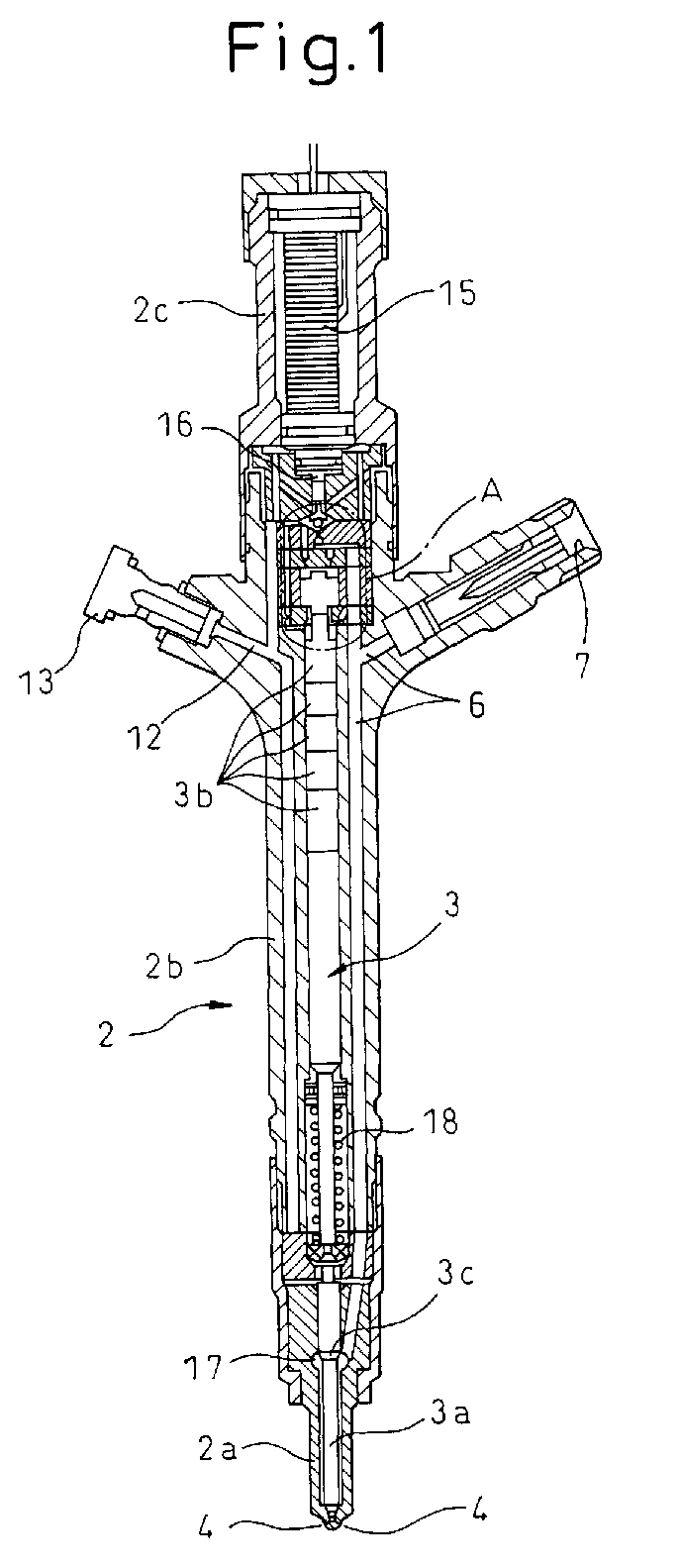
- Fig. 1 is an overall view of a fuel injector according to the present invention;
- Fig. 2 is an enlarged view of a part A in Fig. 1;
- Fig. 3 is a partly enlarged view of the fuel injector;
- Fig. 4 is an enlarged view, similar to Fig. 2, for explaining an operation of a fuel injector shown in Fig. 1;
- Fig. 5 is an enlarged view, similar to Fig. 2, for explaining an operation of a fuel injector shown in Fig. 1;
- Figs. 6 to 11 show various embodiments of the fuel injection; and
- Fig. 12 is an enlarged view, similar to Fig. 2, illustrating another embodiment according to the present invention.
-
- Referring to Figs. 1 to 3, a
fuel injector 1 comprises ahousing 2 and aneedle 3. Thehousing 2 includes a nozzle holder 2a with a pair ofnozzles 4, acasing body 2b, aactuator casing 2c, andchamber defining members needle 3 includes a needle body 3a and a plurality of piston members 3b, and is accommodated in aneedle accommodating chamber 5 formed in thehousing 2, movably along its longitudinal axis. Theneedle 3 is displaced to open or close thenozzles 4. - A
fuel supply conduit 6 is formed in thehousing 2 from afuel inlet 7 formed in thehousing 2 to thenozzles 4. Thefuel inlet 7 is connected to a high pressure fuel source such as a common rail (not shown) with a constant fuel pressure. - A
pressure control chamber 8 is defined between the top end of theneedle 3 and an inner wall of theneedle accommodating chamber 5. In pressure control chamber 8 adisplacement control piston 9 is axially and movably accommodated to divide thepressure control chamber 8 into first and secondpressure control chambers 8a and 8b. The first pressure control chamber 8a is defined between the bottom end of thedisplacement control piston 9 and the top end of theneedle 3, and the secondpressure control chamber 8b is defined between the top end of thedisplacement control piston 9 and the inner wall of theneedle accommodating chamber 5. - The
displacement control piston 9 includes an annular shoulder 9a, which limits a downward displacement of thepiston 9 together with anannular shoulder 5a formed in theneedle accommodating chamber 5. Note that an upward displacement of thepiston 9 is limited by contact between the top end of thepiston 9 and the top end wall of theneedle accommodating chamber 5. - A
valve chamber 10 is also formed in thehousing 2, which is connected to thepressure control chamber 8 via a discharging conduit. Specifically, thevalve chamber 10 is connected to the first pressure control chamber 8a via a firstdischarging conduit 11a, and is connected to the secondpressure control chamber 8b via a seconddischarging conduit 11b. - As described hereinafter, the
pressure control chambers 8a and 8b and thevalve chamber 10 are filled with fuel. -
Relief conduits 12, formed in thehousing 2, extend from thevalve chamber 10 to a fuel outlet 13 formed in thehousing 2. The fuel outlet 13 may be connected to a fuel tank (not shown). - A
pressure control valve 14 is movably accommodated in thevalve chamber 10 along its longitudinal axis. Thepressure control valve 14 includes a ball-shaped member 14a and a rod-shaped member 14b, integral with each other. - The
pressure control valve 14 is driven by anactuator 15, of a piezo-electronic type, accommodated in thehousing 2. Theactuator 15 controls an axial displacement of thepressure control valve 14 though a control of a fuel pressure in a fuel-filledchamber 16 between theactuator 15 and thepressure control valve 14. Specifically, when the actuator extends along its longitudinal axis, a fuel pressure in thechamber 16 increases, and thus thepressure control valve 14 displaces downwardly. When the actuator shrinks along its longitudinal axis, a fuel pressure in thechamber 16 drops, and thus thepressure control valve 14 displaces upwardly. - The
fuel supply conduit 6 includes afuel collecting chamber 17, formed therein, in which a pressure receiving surface 3c, formed on the needle, is arranged. Accordingly, theneedle 3 is urged by the fuel pressure, in thefuel collecting chamber 17, in a direction in which theneedle 3 opens thenozzles 4. Theneedle 3 is also urged by acompressed spring 18, arranged between theneedle 3 and the inner wall of theneedle accommodating chamber 5, in a direction in which theneedle 3 closes thenozzles 4. - A high fuel pressure conduit 19 branches off from the
fuel supply conduit 6, and is connected to the first and the secondpressure control chambers 8a and 8b via first and second inflowingconduit fuel pressure conduit 19 is also connected to thevalve chamber 10 via a third inflowingconduit 20c. - Note that, in the present embodiment, the first and second
discharging conduits conduits - The flow resistance of the second inflowing
conduit 20b is set smaller than that of the first inflowingconduit 20a, and the flow resistance of the second dischargingconduit 11b is set larger than that of the first dischargingconduit 11a. Further, a hydro erosive grinding is applied only in a direction from thevalve chamber 10 to thepressure control chamber 8b, so that a discharge coefficient of the seconddischarging conduit 11b in a direction from the secondpressure control chamber 8b to thevalve chamber 10 is set smaller than that in a direction from thevalve chamber 10 to thepressure control chamber 8b. Therefore, the pressure in the secondpressure control chamber 8b is easily increased but difficult to reduce, with respect to the pressure in the first pressure control chamber 8a. - Fig. 2 shows the case where the
pressure control valve 14 is in a zero-displaced position. In this position, thepressure control valve 14 prevents communication between thevalve chamber 10 and therelief conduits 12, and connects thevalve chamber 10 with the highfuel pressure conduit 19. In this condition, fuel in the highfuel pressure conduit 19 flows into the first pressure control chamber 8a, via the first inflowingconduit 20a, and via the third inflowingconduit 20c, thevalve chamber 10, and the first dischargingconduit 11a. Also, fuel flows into the secondpressure control chamber 8b via the second inflowingconduit 20b, and via the third inflowingconduit 20c, thevalve chamber 10, and the seconddischarging conduit 11b. - This increases the fuel pressure in the second
pressure control chamber 8b, and keeps thedisplacement control piston 9 in a lowermost position where its shoulder 9a contacts with theshoulder 5a of theneedle accommodating chamber 5. Also, this increases the fuel pressure in the first pressure control chamber 8a. Therefore, a downward force acting on theneedle 3 for closing thenozzles 4, which is provided by the fuel pressure in thepressure control chambers 8a and 8b and the biasing force of thespring 18, exceeds an upward force acting on the needle for opening thenozzles 4, which is provided by the fuel pressure in thefuel collecting chamber 17. Accordingly, theneedle 3 closesnozzles 4. - Note that, in this condition, the top of the
needle 3 and the bottom of thedisplacement control piston 9 are spaced apart from each other by a distance D1, and the top of thepiston 9 and the top of the inner wall of theneedle accommodating chamber 5 are spaced apart from each other by a distance D2, as shown in Fig. 3. - Fig. 4 shows the case where the
pressure control valve 14 is in an intermediate position or is displaced by a small displacement SD from the zero-displacement position. In this position, thepressure control valve 14 partly connects thevalve chamber 10 with therelief conduits 12, and connects thevalve chamber 10 with the highfuel pressure conduit 19. In this condition, fuel flows into the first pressure control chamber 8a via the firstinflowing conduit 20a. However, fuel in the first pressure control chamber 8a flows out therefrom via the first dischargingconduit 11a and thevalve chamber 10 to therelief conduits 12. Therefore, the pressure in the first pressure control chamber 8a drops. As a result, the upward force acting on theneedle 3 exceeds the downward force acting on theneedle 3, and thus theneedle 3 is displaced upwardly. - On the other hand, at this time, fuel flows into the second
pressure control chamber 8b via the secondinflowing conduit 20b and the second dischargingconduit 11b. Note that, in the present embodiment, magnitudes of the opening formed between thevalve chamber 10 and therelief conduits 12 and the flow resistances of theconduits valve chamber 10 to the secondpressure control chamber 8b even if thevalve chamber 10 is connected to therelief conduits 12. Therefore, the pressure in the secondpressure control chamber 8b is kept high, and thus thedisplacement control piston 9 is kept at the lowermost position. - The upward displacement of the
needle 3 is limited by an abutment of theneedle 3 with thedisplacement control piston 9, as shown in Fig. 5. In this way, theneedle 3 is displaced by the displacement D1 or partly opens thenozzles 4, by the small displacement of thepressure control valve 14. - Fig. 5 shows the case where the
pressure control valve 14 is in a fully-displaced position or is displaced by a full displacement FD from the zero-displacement position. In this position, thepressure control valve 14 connects thevalve chamber 10 with therelief conduits 12, and prevents communication between thevalve chamber 10 and the highfuel pressure conduit 19. In this condition, the pressure in the first pressure control chamber 8a is kept low because fuel in the first pressure control chamber 8a flows out therefrom via the first dischargingconduit 11a and thevalve chamber 10 to therelief conduits 12. - At this time, fuel in the second
pressure control chamber 8b also flows out therefrom via the second dischargingconduit 11b and thevalve chamber 10 to therelief conduits 12. Therefore, the fuel pressure in the secondpressure control chamber 8b also drops. - As a result, the
displacement control piston 9 is displaced upwardly until it contacts with the inner wall of theneedle accommodating chamber 5, and is kept its uppermost position. Theneedle 3 is also displaced upwardly until it contacts with thedisplacement control piston 9. Therefore, theneedle 3 is displaced by the displacement D2 from the condition shown in Fig. 4 or fully opens thenozzles 4, by the full displacement of thepressure control valve 14. - Figs. 6 to 11 shows various embodiments of the fuel injection.
- In the embodiment shown in Fig. 6, the displacement VD of the
pressure control valve 14 is made equal to and is temporarily kept at the small displacement SD, and then is made equal to and is temporarily kept at the full displacement FD. Then, the valve displacement VD is returned to zero. - As a result, the needle displacement ND is first made equal to and is temporarily kept at the displacement D1, and thus the fuel injection with a fuel injection rate FIR being a low rate RL is performed. The needle displacement ND is then increased to D1 + D2, and thus the fuel injection with the fuel injection rate FIR being a high rate RH is performed.
- If the fuel injection is started with the high injection rate RH, the amount of NOx generated may increase and combustion noise may increase. The fuel injection shown in Fig. 6 is started with the low injection rate RL, and therefore, a generation of NOx, and the combustion noise, are suppressed.
- In the embodiment shown in Fig. 7, the valve displacement VD is continuously increased from the zero-displaced position to the fully-displaced position, and kept at the full displacement FD for a preset time. Then, the valve displacement VD is returned to zero.
- A displacing rate of the
pressure control valve 14 is set so that the needle displacement ND is first made equal to and is temporarily kept at the displacement D1 and then the needle displacement ND is increased to D1 + D2, as in the embodiment shown in Fig. 6. - As a result, the fuel injection with a fuel injection rate FIR being the low rate RL is first performed, and then the fuel injection with the fuel injection rate FIR being the high rate RH is performed.
- As described above, the pressure in the second
pressure control chamber 8b is easily increased but is difficult to reduce, with respect to the pressure in the first pressure control chamber 8a. Therefore, even if the valve displacement VD is smaller than the small displacement SD, theneedle 3 starts displacing upwardly when the upward force acting on theneedle 3 exceeds the downward force acting on theneedle 3. Further, even if the valve displacement VD is larger than the small displacement SD, the needle displacement ND is kept at the displacement D1 as long as thedisplacement control piston 9 is kept at its lowermost position. This means that no precise control of the displacement of thepressure control valve 14 is necessary in order to displace theneedle 3 by the displacement D1. - Further, a fact that the pressure in the second
pressure control chamber 8b is easily increased but is difficult to reduce will promote a rapid displacement of theneedle 3 to close thenozzles 4. - Fig. 8 shows a low-rate fuel injection in which the displacement VD of the
pressure control valve 14 is made equal to, and is temporarily kept at, the small displacement SD, and then is returned to zero. As a result, the needle displacement ND is made equal to, and is temporarily kept at, the displacement D1, and the fuel injection with the low rate RL is performed. The low-rate injection provides a fuel jet having a low penetration force. - As shown in Fig. 9, the valve displacement VD may be temporarily kept at a displacement larger than the small displacement SD, and then, may be temporarily kept at the small displacement SD, when the low-rate fuel injection should be performed. This promotes a rapid displacement of the
needle 3 to open thenozzles 4. - Fig. 10 shows a high-rate fuel injection in which the displacement VD of the
pressure control valve 14 is made equal to, and is temporarily kept at, the full displacement FD, and then is returned to zero. As a result, the needle displacement ND is made equal to, and is temporarily kept at, the displacement D1 + D2, and the fuel injection with the high rate RH is performed. The high-rate injection provides a jet of fuel having a high penetration force. - Fig. 11 shows an embodiment of fuel injections performed in one combustion cycle of an engine, including a main fuel injection and additional fuel injections which is performed in addition to the main fuel injection. The main fuel injection M in the form of the high-rate injection may be performed around the top dead center of the intake stroke of the engine.
- Before the main fuel injection M, two additional injections are performed. Specifically, a first additional injection A1 in the form of the low-rate injection is performed in the intake stroke, and a second additional injection A2 in the form of the high-rate injection is then performed at the end of the compression stroke.
- The first additional injection A1 in the form of the low-rate injection serves to form an air-fuel mixture spreading over the combustion chamber while preventing an adhesion of the additional fuel on the cylinder wall. The second additional injection A2 in the form of the high-rate injection serves to position the additional fuel near the fuel injected by the main fuel injection M, to thereby suppress generation of smoke.
- After the main fuel injection M, two more additional injections are performed. Specifically, a third additional injection A3 in the form of the high-rate injection is performed at the top of the power stroke, and a fourth additional injection A4 in the form of the low-rate injection is then performed in the power or exhaust stroke.
- The third additional injection A3 in the form of the high-rate injection serves to enhance mixing of an air-fuel mixture in the combustion chamber. The fourth additional injection A4 in the form of the low-rate injection serves to feed a reducing agent to a catalyst provided in the exhaust passage for reducing NOx while preventing an adhesion of the additional fuel on the cylinder wall.
- Note that, in the second and third additional injections A2, A3 shown in Fig. 11, the
pressure control valve 14 is kept at the fully-displaced position for a very short time. Therefore, the needle displacement ND does not reach D1 + D2 and the fuel injection rate does not reach the high rate RH. - Fig. 12 shows another embodiment of the fuel injection, in which the first
inflowing conduit 20a is omitted. In this case, the fuel flows into the first pressure control chamber 8a via the first dischargingconduit 11a. - In the embodiments described above, the needle displacement increases when the valve displacement increases. In other words, when the
pressure control valve 14 displaces from the zero-displaced position to the fully-displaced position, it is prevented that the nozzle is first displaced to its fully-displaced position and then its intermediate position. Therefore, a rapid displacement of theneedle 3 is ensured. - Further, in the above embodiments, in order to control a displacement of the
needle 3 or a fuel injection rate, it is only required to control the pressures in the first and secondpressure control chambers 8a and 8b, and it is unnecessary to drive theneedle 3 directly or control the pressure fed to thefuel injector 1. In addition, theactuator 15 is connected to thepressure control valve 14 via the fuel-filledchamber 16, and therefore, no precise control of a displacement of theactuator 15 is necessary. Even if theactuator 15 undesirably extends or shrinks according to its temperature, an undesirable change of the pressures in the first and secondpressure control chambers 8a and 8b is prevented. - Further, in the above embodiments, the fuel is fed to the
fuel injector 1 at a constant fuel pressure. However, if a fuel pump which feeds the fuel to thefuel injector 1 is of an engine-driven type, the pressure of fuel supplied to thefuel injector 1 may vary according to the engine operating condition. In this case, if the fuel pressure becomes high, an amount of the actually injected fuel becomes large and, if the fuel pressure becomes low, the amount of the actually injected fuel becomes small. - In order to avoid this, the low-rate injection may be performed when the fuel pressure is higher than an upper threshold, and the high-rate injection is performed when the fuel pressure is lower than a lower threshold. This avoids an excess or a lack of fuel fed to the engine. Further, when the fuel pressure is high, it is unnecessary to discharge a part of fuel in the
fuel injector 1 therefrom to reduce the amount of the actually injected fuel. - In order to judge whether the fuel pressure is higher than the upper threshold or is lower than the lower threshold, a pressure sensor may be provided in the common rail. Alternatively, it may be judged on the basis of the engine operating condition. Specifically, the fuel pressure will become high during a rapid deceleration just after a heavy-load operation of the engine.
- In the above embodiments, the
needle 3 closes thenozzles 4 when thepressure control valve 14 is in the zero-displaced position, partly opens thenozzles 4 when thevalve 14 is in the intermediate position, and fully opens thenozzles 4 when thevalve 14 is in the fully-displaced position. Alternatively, theneedle 3 closes thenozzles 4 when thevalve 14 is in the fully-displaced position, partly opens thenozzles 4 when thevalve 14 is in the intermediate position, and fully opens thenozzles 4 when thevalve 14 is in the zero-displaced position. - Further, the embodiments described above include the
displacement control piston 9 arranged in thepressure control chamber 8. Alternatively, thepiston 9 may be omitted to provide a single pressure control chamber, a single inflowing conduit, and a single discharging conduit. - According to the present invention, it is possible to provide a fuel injector which is capable of rapidly displacing the needle.
- A fuel injector comprising a housing with a nozzle, a needle movably accommodated in a needle accommodating chamber formed in the housing, for opening or closing the nozzle, a pressure control chamber defined between the needle and an inner wall of the needle accommodating chamber and filled with a fuel, a displacement of the needle depending on the fuel pressure in the pressure control chamber, a pressure control valve movably provided in the housing for controlling the fuel pressure in the pressure control chamber; and an actuator for controlling a displacement of the pressure control valve. The needle is displaced to a position in which it closes the nozzle when the pressure control valve is displaced to the zero-displaced position, is displaced to a position in which it partly opens the nozzle when the pressure control valve is displaced to an intermediate position, and is displaced to a position in which it fully opens the nozzle when the pressure control valve is displaced to a fully-displaced position.
Claims (17)
- A fuel injector comprising:wherein the needle is displaced by a first displacement when the pressure control valve is displaced to the zero-displaced position,a housing with a nozzle;a needle movably accommodated in a needle accommodating chamber formed in the housing, for opening or closing the nozzle;a pressure control chamber defined between the needle and an inner wall of the needle accommodating chamber and filled with a fuel, a displacement of the needle depending on the fuel pressure in the pressure control chamber;a pressure control valve movably provided in the housing for controlling the fuel pressure in the pressure control chamber; andan actuator for controlling a displacement of the pressure control valve;
wherein the needle is displaced by a second displacement when the pressure control valve is displaced to the fully-displaced position,
wherein the needle is displaced by a third displacement when the pressure control valve is displaced to an intermediate position between the zero-displaced position and the fully-displaced position, and
wherein the third displacement is between the first and second displacements. - A fuel injector according to claim 1, wherein the needle closes the nozzle when it is displaced by the first displacement, wherein the needle partly opens the nozzle when it is displaced by the third displacement, and wherein the needle fully opens the nozzle when it is displaced by the second displacement.
- A fuel injector according to claim 2, wherein a displacement control piston is movably accommodated in the pressure control chamber, the displacement control piston dividing the pressure control chamber into first and second pressure control chambers, the first pressure control chamber being defined between the displacement control piston and the needle, and the second pressure control chamber being defined between the displacement control piston and the inner wall of the needle accommodating chamber, wherein a valve chamber filled with the fuel is formed in the housing to accommodate the pressure control valve therein, wherein a high fuel pressure source is connected to the second pressure control chamber and the valve chamber via second and third inflowing conduits respectively, and the first and second pressure control chambers are connected to the valve chamber via first and second discharging conduits, respectively, and wherein the pressure control valve controls a connection between the valve chamber and a relief conduit and a connection between the valve chamber and the high fuel pressure source.
- A fuel injector according to claim 3, wherein the pressure control valve prevents communication between the valve chamber and the relief conduit and connects the valve chamber to the high fuel pressure source when it is displaced to the zero-displaced position, wherein the pressure control valve partly connects the valve chamber to the relief conduit and connects the valve chamber to the high fuel pressure source when it is displaced to the intermediate position, and wherein the pressure control valve connects the valve chamber to the relief conduit and prevents communication between the valve chamber and the high fuel pressure source when it is displaced to the fully-displaced position.
- A fuel injector according to claim 3, wherein the first pressure control chamber is connected to the high fuel pressure source via a first inflowing conduit.
- A fuel injector according to claim 5, wherein a flow resistance of the second inflowing conduit is set smaller than that of the first inflowing conduit.
- A fuel injector according to claim 3, wherein a flow resistance of the second discharging conduit is set larger than that of the first discharging conduit.
- A fuel injector according to claim 3, wherein a discharge coefficient of the second discharging conduit in a direction from the second pressure control chamber to the valve chamber is set smaller than that in a direction from the valve chamber to the second pressure control chamber.
- A fuel injector according to claim 3, wherein the high fuel pressure source comprises a fuel supply conduit extending the housing to the nozzle.
- A fuel injector according to claim 2, wherein the pressure control valve is displaced to and temporarily maintained at the intermediate position so that the needle temporarily opens the nozzle partly, and is then displaced to the fully-displaced position so that the needle opens the nozzle fully, and is then returned to the zero-displaced position so that the needle closes the nozzle.
- A fuel injector according to claim 2, wherein the pressure control valve is displaced from the zero-displaced position to the fully-displaced position continuously, with a displacing rate of the pressure control valve being set so that the needle temporarily opens the nozzle partly and then opens the nozzle fully.
- A fuel injector according to claim 2, wherein the fuel injector selectively performs one of a low-rate fuel injection in which the pressure control valve is displaced to the intermediate position and is then returned to the zero-displaced position, and a high-rate fuel injection in which the pressure control valve is displaced to the fully-displaced position and is then returned to the zero-displaced position.
- A fuel injector according to claim 12, wherein, before a main fuel injection, the fuel injector additionally performs the low-rate fuel injection and the high-rate fuel injection, in turn.
- A fuel injector according to claim 12, wherein, after a main fuel injection, the fuel injector additionally performs the high-rate fuel injection and the low-rate fuel injection, in turn.
- A fuel injector according to claim 12, wherein, when the fuel injector should perform the low-rate fuel injection, the pressure control valve is temporarily displaced by a displacement larger than a displacement required for the intermediate position.
- A fuel injector according to claim 12, wherein, when the pressure of fuel supplied to the fuel injector is higher than an upper threshold, the fuel injector performs the low-rate fuel injection.
- A fuel injector according to claim 12, wherein when the pressure of fuel supplied to the fuel injector is lower than a lower threshold, the fuel injector performs the high-rate fuel injection.
Applications Claiming Priority (2)
| Application Number | Priority Date | Filing Date | Title |
|---|---|---|---|
| JP2000275012A JP3804421B2 (en) | 2000-09-06 | 2000-09-06 | Fuel injection device |
| JP2000275012 | 2000-09-06 |
Publications (3)
| Publication Number | Publication Date |
|---|---|
| EP1186773A2 true EP1186773A2 (en) | 2002-03-13 |
| EP1186773A3 EP1186773A3 (en) | 2004-01-07 |
| EP1186773B1 EP1186773B1 (en) | 2005-01-19 |
Family
ID=18760696
Family Applications (1)
| Application Number | Title | Priority Date | Filing Date |
|---|---|---|---|
| EP20010121254 Expired - Lifetime EP1186773B1 (en) | 2000-09-06 | 2001-09-05 | Fuel injector |
Country Status (4)
| Country | Link |
|---|---|
| EP (1) | EP1186773B1 (en) |
| JP (1) | JP3804421B2 (en) |
| DE (1) | DE60108454T2 (en) |
| ES (1) | ES2231365T3 (en) |
Cited By (6)
| Publication number | Priority date | Publication date | Assignee | Title |
|---|---|---|---|---|
| EP1304475A1 (en) * | 2001-10-20 | 2003-04-23 | Robert Bosch Gmbh | Fuel injection valve |
| WO2006134003A1 (en) * | 2005-06-16 | 2006-12-21 | Robert Bosch Gmbh | Fuel injection valve for internal combustion engines |
| WO2007098985A1 (en) * | 2006-02-28 | 2007-09-07 | Robert Bosch Gmbh | Fuel injection valve |
| EP2025918A1 (en) * | 2007-07-30 | 2009-02-18 | Robert Bosch GmbH | Fuel injection valve device |
| EP2426349A1 (en) * | 2010-09-07 | 2012-03-07 | Robert Bosch GmbH | Fuel injector |
| US20160237937A1 (en) * | 2013-09-25 | 2016-08-18 | Hitachi Automotive Systems, Ltd. | Drive Device for Fuel Injection Device |
Families Citing this family (5)
| Publication number | Priority date | Publication date | Assignee | Title |
|---|---|---|---|---|
| JP5210791B2 (en) * | 2008-10-08 | 2013-06-12 | 株式会社日本自動車部品総合研究所 | Fuel injection device |
| JP5056966B2 (en) * | 2011-03-10 | 2012-10-24 | 株式会社豊田自動織機 | Combustion control device |
| JP5745934B2 (en) * | 2011-05-23 | 2015-07-08 | 株式会社日本自動車部品総合研究所 | Fuel injection control device |
| JP6726130B2 (en) * | 2017-04-13 | 2020-07-22 | 日立オートモティブシステムズ株式会社 | Driving device for fuel injection device |
| JP2020041509A (en) * | 2018-09-12 | 2020-03-19 | 日立オートモティブシステムズ株式会社 | Control device for internal combustion engine and fuel injection valve |
Citations (1)
| Publication number | Priority date | Publication date | Assignee | Title |
|---|---|---|---|---|
| JPH08334072A (en) | 1995-06-06 | 1996-12-17 | Nissan Motor Co Ltd | Fuel injection control device for internal combustion engine |
Family Cites Families (3)
| Publication number | Priority date | Publication date | Assignee | Title |
|---|---|---|---|---|
| DE19624001A1 (en) * | 1996-06-15 | 1997-12-18 | Bosch Gmbh Robert | Fuel injection device for internal combustion engines |
| DE19741850A1 (en) * | 1997-09-23 | 1999-03-25 | Bosch Gmbh Robert | Injection valve for fuel injection system for IC engine |
| JP3557996B2 (en) * | 1999-06-21 | 2004-08-25 | トヨタ自動車株式会社 | Fuel injection device |
-
2000
- 2000-09-06 JP JP2000275012A patent/JP3804421B2/en not_active Expired - Fee Related
-
2001
- 2001-09-05 DE DE2001608454 patent/DE60108454T2/en not_active Expired - Fee Related
- 2001-09-05 EP EP20010121254 patent/EP1186773B1/en not_active Expired - Lifetime
- 2001-09-05 ES ES01121254T patent/ES2231365T3/en not_active Expired - Lifetime
Patent Citations (1)
| Publication number | Priority date | Publication date | Assignee | Title |
|---|---|---|---|---|
| JPH08334072A (en) | 1995-06-06 | 1996-12-17 | Nissan Motor Co Ltd | Fuel injection control device for internal combustion engine |
Cited By (8)
| Publication number | Priority date | Publication date | Assignee | Title |
|---|---|---|---|---|
| EP1304475A1 (en) * | 2001-10-20 | 2003-04-23 | Robert Bosch Gmbh | Fuel injection valve |
| WO2006134003A1 (en) * | 2005-06-16 | 2006-12-21 | Robert Bosch Gmbh | Fuel injection valve for internal combustion engines |
| WO2007098985A1 (en) * | 2006-02-28 | 2007-09-07 | Robert Bosch Gmbh | Fuel injection valve |
| EP2025918A1 (en) * | 2007-07-30 | 2009-02-18 | Robert Bosch GmbH | Fuel injection valve device |
| EP2426349A1 (en) * | 2010-09-07 | 2012-03-07 | Robert Bosch GmbH | Fuel injector |
| US20160237937A1 (en) * | 2013-09-25 | 2016-08-18 | Hitachi Automotive Systems, Ltd. | Drive Device for Fuel Injection Device |
| EP3051108A4 (en) * | 2013-09-25 | 2017-04-19 | Hitachi Automotive Systems, Ltd. | Drive device for fuel injection device |
| US10677184B2 (en) | 2013-09-25 | 2020-06-09 | Hitachi Automotive Systems, Ltd. | Drive device for fuel injection device |
Also Published As
| Publication number | Publication date |
|---|---|
| JP3804421B2 (en) | 2006-08-02 |
| DE60108454D1 (en) | 2005-02-24 |
| DE60108454T2 (en) | 2005-06-30 |
| JP2002081358A (en) | 2002-03-22 |
| EP1186773B1 (en) | 2005-01-19 |
| EP1186773A3 (en) | 2004-01-07 |
| ES2231365T3 (en) | 2005-05-16 |
Similar Documents
| Publication | Publication Date | Title |
|---|---|---|
| KR100634031B1 (en) | Fuel supply device of internal combustion engine | |
| US5823161A (en) | Fuel injection device for internal combustion engines | |
| JP5549293B2 (en) | Fuel injection device | |
| EP1186773B1 (en) | Fuel injector | |
| EP1612401B1 (en) | An injection system for an internal combustion engine | |
| GB1590666A (en) | Fuel injection arrangements for internal combustion engines | |
| JP2003328898A (en) | Fuel injection device for internal combustion engines | |
| GB2324343A (en) | A control valve for a high pressure fuel pump in a fuel supply system providing pre-injection and main injection for an i.c. engine | |
| US6427664B1 (en) | Pressure booster for a fuel injection system for internal combustion engines | |
| KR20010082242A (en) | Magnetic injector for accumulator fuel injection system | |
| US6598811B2 (en) | Pressure controlled injector for injecting fuel | |
| US6637409B2 (en) | Fuel injection device for internal combustion engines | |
| EP1184563B1 (en) | Fuel injector | |
| JP2005500467A (en) | Fuel injection device used for internal combustion engine | |
| US20020129792A1 (en) | Fuel injection apparatus for internal combustion engines | |
| KR20060054347A (en) | Fuel injectors for engines | |
| JP3610112B2 (en) | Fuel supply system for diesel engine | |
| EP1065368A2 (en) | Fuel injector | |
| JP3744577B2 (en) | Accumulated fuel injection system | |
| EP1236883A2 (en) | Fuel system | |
| US20040020458A1 (en) | Method for operating a pump-nozzle unit and a corresponding pump-nozzle unit | |
| CN114738155B (en) | Fuel injection valve assembly, engine and vehicle | |
| JP2526856B2 (en) | Fuel injection device capable of injecting two kinds of fuel sequentially | |
| JPH11229999A (en) | Metering mechanism for high-pressure fuel pump | |
| JP2760040B2 (en) | Unit injector fuel supply and discharge device |
Legal Events
| Date | Code | Title | Description |
|---|---|---|---|
| PUAI | Public reference made under article 153(3) epc to a published international application that has entered the european phase |
Free format text: ORIGINAL CODE: 0009012 |
|
| 17P | Request for examination filed |
Effective date: 20010905 |
|
| AK | Designated contracting states |
Kind code of ref document: A2 Designated state(s): AT BE CH CY DE DK ES FI FR GB GR IE IT LI LU MC NL PT SE TR |
|
| AX | Request for extension of the european patent |
Free format text: AL;LT;LV;MK;RO;SI |
|
| RIC1 | Information provided on ipc code assigned before grant |
Ipc: 7F 02M 59/46 B Ipc: 7F 02M 47/02 A Ipc: 7F 02M 45/12 B |
|
| PUAL | Search report despatched |
Free format text: ORIGINAL CODE: 0009013 |
|
| AK | Designated contracting states |
Kind code of ref document: A3 Designated state(s): AT BE CH CY DE DK ES FI FR GB GR IE IT LI LU MC NL PT SE TR |
|
| AX | Request for extension of the european patent |
Extension state: AL LT LV MK RO SI |
|
| 17Q | First examination report despatched |
Effective date: 20040210 |
|
| GRAP | Despatch of communication of intention to grant a patent |
Free format text: ORIGINAL CODE: EPIDOSNIGR1 |
|
| AKX | Designation fees paid |
Designated state(s): DE ES FR GB IT SE |
|
| GRAS | Grant fee paid |
Free format text: ORIGINAL CODE: EPIDOSNIGR3 |
|
| GRAA | (expected) grant |
Free format text: ORIGINAL CODE: 0009210 |
|
| AK | Designated contracting states |
Kind code of ref document: B1 Designated state(s): DE ES FR GB IT SE |
|
| REG | Reference to a national code |
Ref country code: GB Ref legal event code: FG4D |
|
| REG | Reference to a national code |
Ref country code: SE Ref legal event code: TRGR |
|
| REG | Reference to a national code |
Ref country code: IE Ref legal event code: FG4D |
|
| REF | Corresponds to: |
Ref document number: 60108454 Country of ref document: DE Date of ref document: 20050224 Kind code of ref document: P |
|
| REG | Reference to a national code |
Ref country code: ES Ref legal event code: FG2A Ref document number: 2231365 Country of ref document: ES Kind code of ref document: T3 |
|
| ET | Fr: translation filed | ||
| PLBE | No opposition filed within time limit |
Free format text: ORIGINAL CODE: 0009261 |
|
| STAA | Information on the status of an ep patent application or granted ep patent |
Free format text: STATUS: NO OPPOSITION FILED WITHIN TIME LIMIT |
|
| 26N | No opposition filed |
Effective date: 20051020 |
|
| PGFP | Annual fee paid to national office [announced via postgrant information from national office to epo] |
Ref country code: FR Payment date: 20080915 Year of fee payment: 8 |
|
| PGFP | Annual fee paid to national office [announced via postgrant information from national office to epo] |
Ref country code: GB Payment date: 20080910 Year of fee payment: 8 |
|
| PGFP | Annual fee paid to national office [announced via postgrant information from national office to epo] |
Ref country code: DE Payment date: 20080919 Year of fee payment: 8 |
|
| PGFP | Annual fee paid to national office [announced via postgrant information from national office to epo] |
Ref country code: ES Payment date: 20080930 Year of fee payment: 8 Ref country code: SE Payment date: 20080908 Year of fee payment: 8 |
|
| PGFP | Annual fee paid to national office [announced via postgrant information from national office to epo] |
Ref country code: IT Payment date: 20080927 Year of fee payment: 8 |
|
| EUG | Se: european patent has lapsed | ||
| GBPC | Gb: european patent ceased through non-payment of renewal fee |
Effective date: 20090905 |
|
| REG | Reference to a national code |
Ref country code: FR Ref legal event code: ST Effective date: 20100531 |
|
| PG25 | Lapsed in a contracting state [announced via postgrant information from national office to epo] |
Ref country code: FR Free format text: LAPSE BECAUSE OF NON-PAYMENT OF DUE FEES Effective date: 20090930 Ref country code: DE Free format text: LAPSE BECAUSE OF NON-PAYMENT OF DUE FEES Effective date: 20100401 |
|
| PG25 | Lapsed in a contracting state [announced via postgrant information from national office to epo] |
Ref country code: GB Free format text: LAPSE BECAUSE OF NON-PAYMENT OF DUE FEES Effective date: 20090905 |
|
| PG25 | Lapsed in a contracting state [announced via postgrant information from national office to epo] |
Ref country code: IT Free format text: LAPSE BECAUSE OF NON-PAYMENT OF DUE FEES Effective date: 20090905 |
|
| PG25 | Lapsed in a contracting state [announced via postgrant information from national office to epo] |
Ref country code: SE Free format text: LAPSE BECAUSE OF NON-PAYMENT OF DUE FEES Effective date: 20090906 |
|
| REG | Reference to a national code |
Ref country code: ES Ref legal event code: FD2A Effective date: 20110714 |
|
| PG25 | Lapsed in a contracting state [announced via postgrant information from national office to epo] |
Ref country code: ES Free format text: LAPSE BECAUSE OF NON-PAYMENT OF DUE FEES Effective date: 20110704 |
|
| PG25 | Lapsed in a contracting state [announced via postgrant information from national office to epo] |
Ref country code: ES Free format text: LAPSE BECAUSE OF NON-PAYMENT OF DUE FEES Effective date: 20090906 |