EP1186757A2 - Abgasreinigungsanlage einer Brennkraftmaschine mit einer Kühleinheit - Google Patents
Abgasreinigungsanlage einer Brennkraftmaschine mit einer Kühleinheit Download PDFInfo
- Publication number
- EP1186757A2 EP1186757A2 EP01119991A EP01119991A EP1186757A2 EP 1186757 A2 EP1186757 A2 EP 1186757A2 EP 01119991 A EP01119991 A EP 01119991A EP 01119991 A EP01119991 A EP 01119991A EP 1186757 A2 EP1186757 A2 EP 1186757A2
- Authority
- EP
- European Patent Office
- Prior art keywords
- exhaust gas
- nitrogen oxide
- cooling unit
- exhaust
- catalytic converter
- Prior art date
- Legal status (The legal status is an assumption and is not a legal conclusion. Google has not performed a legal analysis and makes no representation as to the accuracy of the status listed.)
- Withdrawn
Links
Images


Classifications
-
- F—MECHANICAL ENGINEERING; LIGHTING; HEATING; WEAPONS; BLASTING
- F01—MACHINES OR ENGINES IN GENERAL; ENGINE PLANTS IN GENERAL; STEAM ENGINES
- F01N—GAS-FLOW SILENCERS OR EXHAUST APPARATUS FOR MACHINES OR ENGINES IN GENERAL; GAS-FLOW SILENCERS OR EXHAUST APPARATUS FOR INTERNAL-COMBUSTION ENGINES
- F01N9/00—Electrical control of exhaust gas treating apparatus
- F01N9/005—Electrical control of exhaust gas treating apparatus using models instead of sensors to determine operating characteristics of exhaust systems, e.g. calculating catalyst temperature instead of measuring it directly
-
- F—MECHANICAL ENGINEERING; LIGHTING; HEATING; WEAPONS; BLASTING
- F01—MACHINES OR ENGINES IN GENERAL; ENGINE PLANTS IN GENERAL; STEAM ENGINES
- F01N—GAS-FLOW SILENCERS OR EXHAUST APPARATUS FOR MACHINES OR ENGINES IN GENERAL; GAS-FLOW SILENCERS OR EXHAUST APPARATUS FOR INTERNAL-COMBUSTION ENGINES
- F01N13/00—Exhaust or silencing apparatus characterised by constructional features
- F01N13/009—Exhaust or silencing apparatus characterised by constructional features having two or more separate purifying devices arranged in series
-
- F—MECHANICAL ENGINEERING; LIGHTING; HEATING; WEAPONS; BLASTING
- F01—MACHINES OR ENGINES IN GENERAL; ENGINE PLANTS IN GENERAL; STEAM ENGINES
- F01N—GAS-FLOW SILENCERS OR EXHAUST APPARATUS FOR MACHINES OR ENGINES IN GENERAL; GAS-FLOW SILENCERS OR EXHAUST APPARATUS FOR INTERNAL-COMBUSTION ENGINES
- F01N3/00—Exhaust or silencing apparatus having means for purifying, rendering innocuous, or otherwise treating exhaust
- F01N3/02—Exhaust or silencing apparatus having means for purifying, rendering innocuous, or otherwise treating exhaust for cooling, or for removing solid constituents of, exhaust
- F01N3/04—Exhaust or silencing apparatus having means for purifying, rendering innocuous, or otherwise treating exhaust for cooling, or for removing solid constituents of, exhaust using liquids
- F01N3/043—Exhaust or silencing apparatus having means for purifying, rendering innocuous, or otherwise treating exhaust for cooling, or for removing solid constituents of, exhaust using liquids without contact between liquid and exhaust gases
-
- F—MECHANICAL ENGINEERING; LIGHTING; HEATING; WEAPONS; BLASTING
- F01—MACHINES OR ENGINES IN GENERAL; ENGINE PLANTS IN GENERAL; STEAM ENGINES
- F01N—GAS-FLOW SILENCERS OR EXHAUST APPARATUS FOR MACHINES OR ENGINES IN GENERAL; GAS-FLOW SILENCERS OR EXHAUST APPARATUS FOR INTERNAL-COMBUSTION ENGINES
- F01N3/00—Exhaust or silencing apparatus having means for purifying, rendering innocuous, or otherwise treating exhaust
- F01N3/02—Exhaust or silencing apparatus having means for purifying, rendering innocuous, or otherwise treating exhaust for cooling, or for removing solid constituents of, exhaust
- F01N3/05—Exhaust or silencing apparatus having means for purifying, rendering innocuous, or otherwise treating exhaust for cooling, or for removing solid constituents of, exhaust by means of air, e.g. by mixing exhaust with air
-
- F—MECHANICAL ENGINEERING; LIGHTING; HEATING; WEAPONS; BLASTING
- F01—MACHINES OR ENGINES IN GENERAL; ENGINE PLANTS IN GENERAL; STEAM ENGINES
- F01N—GAS-FLOW SILENCERS OR EXHAUST APPARATUS FOR MACHINES OR ENGINES IN GENERAL; GAS-FLOW SILENCERS OR EXHAUST APPARATUS FOR INTERNAL-COMBUSTION ENGINES
- F01N3/00—Exhaust or silencing apparatus having means for purifying, rendering innocuous, or otherwise treating exhaust
- F01N3/08—Exhaust or silencing apparatus having means for purifying, rendering innocuous, or otherwise treating exhaust for rendering innocuous
- F01N3/0807—Exhaust or silencing apparatus having means for purifying, rendering innocuous, or otherwise treating exhaust for rendering innocuous by using absorbents or adsorbents
- F01N3/0814—Exhaust or silencing apparatus having means for purifying, rendering innocuous, or otherwise treating exhaust for rendering innocuous by using absorbents or adsorbents combined with catalytic converters, e.g. NOx absorption/storage reduction catalysts
-
- F—MECHANICAL ENGINEERING; LIGHTING; HEATING; WEAPONS; BLASTING
- F01—MACHINES OR ENGINES IN GENERAL; ENGINE PLANTS IN GENERAL; STEAM ENGINES
- F01N—GAS-FLOW SILENCERS OR EXHAUST APPARATUS FOR MACHINES OR ENGINES IN GENERAL; GAS-FLOW SILENCERS OR EXHAUST APPARATUS FOR INTERNAL-COMBUSTION ENGINES
- F01N3/00—Exhaust or silencing apparatus having means for purifying, rendering innocuous, or otherwise treating exhaust
- F01N3/08—Exhaust or silencing apparatus having means for purifying, rendering innocuous, or otherwise treating exhaust for rendering innocuous
- F01N3/0807—Exhaust or silencing apparatus having means for purifying, rendering innocuous, or otherwise treating exhaust for rendering innocuous by using absorbents or adsorbents
- F01N3/0828—Exhaust or silencing apparatus having means for purifying, rendering innocuous, or otherwise treating exhaust for rendering innocuous by using absorbents or adsorbents characterised by the absorbed or adsorbed substances
- F01N3/0842—Nitrogen oxides
-
- F—MECHANICAL ENGINEERING; LIGHTING; HEATING; WEAPONS; BLASTING
- F01—MACHINES OR ENGINES IN GENERAL; ENGINE PLANTS IN GENERAL; STEAM ENGINES
- F01N—GAS-FLOW SILENCERS OR EXHAUST APPARATUS FOR MACHINES OR ENGINES IN GENERAL; GAS-FLOW SILENCERS OR EXHAUST APPARATUS FOR INTERNAL-COMBUSTION ENGINES
- F01N3/00—Exhaust or silencing apparatus having means for purifying, rendering innocuous, or otherwise treating exhaust
- F01N3/08—Exhaust or silencing apparatus having means for purifying, rendering innocuous, or otherwise treating exhaust for rendering innocuous
- F01N3/0807—Exhaust or silencing apparatus having means for purifying, rendering innocuous, or otherwise treating exhaust for rendering innocuous by using absorbents or adsorbents
- F01N3/0871—Exhaust or silencing apparatus having means for purifying, rendering innocuous, or otherwise treating exhaust for rendering innocuous by using absorbents or adsorbents using means for controlling, e.g. purging, the absorbents or adsorbents
-
- F—MECHANICAL ENGINEERING; LIGHTING; HEATING; WEAPONS; BLASTING
- F01—MACHINES OR ENGINES IN GENERAL; ENGINE PLANTS IN GENERAL; STEAM ENGINES
- F01N—GAS-FLOW SILENCERS OR EXHAUST APPARATUS FOR MACHINES OR ENGINES IN GENERAL; GAS-FLOW SILENCERS OR EXHAUST APPARATUS FOR INTERNAL-COMBUSTION ENGINES
- F01N3/00—Exhaust or silencing apparatus having means for purifying, rendering innocuous, or otherwise treating exhaust
- F01N3/08—Exhaust or silencing apparatus having means for purifying, rendering innocuous, or otherwise treating exhaust for rendering innocuous
- F01N3/10—Exhaust or silencing apparatus having means for purifying, rendering innocuous, or otherwise treating exhaust for rendering innocuous by thermal or catalytic conversion of noxious components of exhaust
- F01N3/18—Exhaust or silencing apparatus having means for purifying, rendering innocuous, or otherwise treating exhaust for rendering innocuous by thermal or catalytic conversion of noxious components of exhaust characterised by methods of operation; Control
- F01N3/20—Exhaust or silencing apparatus having means for purifying, rendering innocuous, or otherwise treating exhaust for rendering innocuous by thermal or catalytic conversion of noxious components of exhaust characterised by methods of operation; Control specially adapted for catalytic conversion
-
- F—MECHANICAL ENGINEERING; LIGHTING; HEATING; WEAPONS; BLASTING
- F01—MACHINES OR ENGINES IN GENERAL; ENGINE PLANTS IN GENERAL; STEAM ENGINES
- F01N—GAS-FLOW SILENCERS OR EXHAUST APPARATUS FOR MACHINES OR ENGINES IN GENERAL; GAS-FLOW SILENCERS OR EXHAUST APPARATUS FOR INTERNAL-COMBUSTION ENGINES
- F01N2240/00—Combination or association of two or more different exhaust treating devices, or of at least one such device with an auxiliary device, not covered by indexing codes F01N2230/00 or F01N2250/00, one of the devices being
- F01N2240/02—Combination or association of two or more different exhaust treating devices, or of at least one such device with an auxiliary device, not covered by indexing codes F01N2230/00 or F01N2250/00, one of the devices being a heat exchanger
-
- F—MECHANICAL ENGINEERING; LIGHTING; HEATING; WEAPONS; BLASTING
- F01—MACHINES OR ENGINES IN GENERAL; ENGINE PLANTS IN GENERAL; STEAM ENGINES
- F01N—GAS-FLOW SILENCERS OR EXHAUST APPARATUS FOR MACHINES OR ENGINES IN GENERAL; GAS-FLOW SILENCERS OR EXHAUST APPARATUS FOR INTERNAL-COMBUSTION ENGINES
- F01N2410/00—By-passing, at least partially, exhaust from inlet to outlet of apparatus, to atmosphere or to other device
- F01N2410/02—By-passing, at least partially, exhaust from inlet to outlet of apparatus, to atmosphere or to other device in case of high temperature, e.g. overheating of catalytic reactor
-
- F—MECHANICAL ENGINEERING; LIGHTING; HEATING; WEAPONS; BLASTING
- F01—MACHINES OR ENGINES IN GENERAL; ENGINE PLANTS IN GENERAL; STEAM ENGINES
- F01N—GAS-FLOW SILENCERS OR EXHAUST APPARATUS FOR MACHINES OR ENGINES IN GENERAL; GAS-FLOW SILENCERS OR EXHAUST APPARATUS FOR INTERNAL-COMBUSTION ENGINES
- F01N2570/00—Exhaust treating apparatus eliminating, absorbing or adsorbing specific elements or compounds
- F01N2570/14—Nitrogen oxides
-
- Y—GENERAL TAGGING OF NEW TECHNOLOGICAL DEVELOPMENTS; GENERAL TAGGING OF CROSS-SECTIONAL TECHNOLOGIES SPANNING OVER SEVERAL SECTIONS OF THE IPC; TECHNICAL SUBJECTS COVERED BY FORMER USPC CROSS-REFERENCE ART COLLECTIONS [XRACs] AND DIGESTS
- Y02—TECHNOLOGIES OR APPLICATIONS FOR MITIGATION OR ADAPTATION AGAINST CLIMATE CHANGE
- Y02A—TECHNOLOGIES FOR ADAPTATION TO CLIMATE CHANGE
- Y02A50/00—TECHNOLOGIES FOR ADAPTATION TO CLIMATE CHANGE in human health protection, e.g. against extreme weather
- Y02A50/20—Air quality improvement or preservation, e.g. vehicle emission control or emission reduction by using catalytic converters
-
- Y—GENERAL TAGGING OF NEW TECHNOLOGICAL DEVELOPMENTS; GENERAL TAGGING OF CROSS-SECTIONAL TECHNOLOGIES SPANNING OVER SEVERAL SECTIONS OF THE IPC; TECHNICAL SUBJECTS COVERED BY FORMER USPC CROSS-REFERENCE ART COLLECTIONS [XRACs] AND DIGESTS
- Y02—TECHNOLOGIES OR APPLICATIONS FOR MITIGATION OR ADAPTATION AGAINST CLIMATE CHANGE
- Y02T—CLIMATE CHANGE MITIGATION TECHNOLOGIES RELATED TO TRANSPORTATION
- Y02T10/00—Road transport of goods or passengers
- Y02T10/10—Internal combustion engine [ICE] based vehicles
- Y02T10/40—Engine management systems
Definitions
- the invention relates to an exhaust gas purification system for a Internal combustion engine with a catalyst, at least one Nitrogen oxide storage catalyst, at least one Exhaust gas temperature sensor and an exhaust gas cooling unit for control the temperature of the nitrogen oxide storage catalyst flowing exhaust gas, the exhaust gas cooling unit between the catalyst and the nitrogen oxide storage catalyst is arranged.
- DE 19703295A1 describes a method and a device Known to control the exhaust gas temperature in an exhaust system. In this process, the temperature of the nitrogen oxide trap determined and the exhaust gas temperature in one device corresponding to the optimal efficiency of the nitrogen oxide trap Temperature range changed.
- the one used Cooling device for temperature control is in front of the Catalyst arrangement provided which a Has three-way catalyst and a nitrogen oxide trap. there the exhaust gas temperature is controlled such that a Damage to the nitrogen oxide trap is avoided.
- the conversion rate of the Three-way catalyst set significantly different from that Depend on temperature. It is known to have high implementation rates with a three-way catalytic converter only at temperatures between 330 ° C and 800 ° C can be reached. Therefore one Control of the exhaust gas temperature in an optimal Efficiency of the nitrogen oxide trap corresponding Temperature range the efficiency of the three-way catalyst adversely affect because the optimal efficiency of a Nitrogen oxide trap in a temperature range from about 250 ° C to 450 ° C is achieved.
- the invention has for its object a Exhaust gas cleaning system of an internal combustion engine ready for place, with an operation of the emission control system with an optimal efficiency of the nitrogen oxide trap and Catalyst is achieved, the operation of the Exhaust gas cleaning system a permanent temperature protection for the Nitrogen oxide storage catalytic converter even at high occurring Exhaust gas temperatures in full load operation of the internal combustion engine is guaranteed.
- the inventive arrangement of the exhaust gas cooling unit behind a three-way catalytic converter ensures a reduction in Exhaust gas temperatures to a level, which from the exit from the Exhaust gas cooling unit until the exhaust gas enters the Nitrogen oxide storage catalyst remains approximately constant. Is the Exhaust cooling unit positioned in front of the three-way catalytic converter, then the exhaust gas temperature is lowered first, but then after Flow through the three-way catalyst due to the exothermic Reactions in the three-way catalyst in turn increase, and thus before entering the nitrogen oxide storage catalyst again reach a higher temperature level. In this case it remains the risk of damage to the nitrogen oxide storage catalyst available.
- the Exhaust gas cooling unit the advantage of better near the engine Placement of the emission control system without risk of overheating.
- a cooling device in the exhaust pipe between the three-way catalytic converter and nitrogen oxide storage catalytic converter arranged.
- the cooling device contains one controllable exhaust flap, a main exhaust pipe and one Bypass line.
- the bypass line has longer exhaust gas paths than the main exhaust pipe, making larger in the bypass pipe Exhaust gas heat losses occur.
- the exhaust flap is in Controlled depending on various parameters, whereby control pneumatically, hydraulically or electrically can be done.
- the exhaust flap on the Junction point of the bypass line is arranged so that it is able to the main exhaust line or the bypass line to be closed completely, with an intermediate position for Redirection of a certain proportion of the exhaust gas mass flow in the bypass line is adjustable.
- the exhaust flap is in the bypass line arranged that the main exhaust line always remains open.
- the diameter of the Main exhaust pipe dimensioned so that when controlling the Exhaust temperature prevents damage to the nitrogen oxide trap becomes.
- An advantageous development of the invention is through the special positioning of one in the bypass line arranged cooler in the form of a heat exchanger.
- the exhaust gas is passed through the bypass line into the cooler is operated with a coolant.
- the flow can of the coolant depending on the operating parameters by the Motor control can be regulated. This can be used as a coolant Engine cooling water or air conveyed by a fan serve. With a suitable design of the heat exchanger for example, the airstream can also be used for direct cooling.
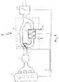
- An exhaust gas purification system 1 for an internal combustion engine 2 1 consists of a three-way catalyst 3, one Cooling device 4, a nitrogen oxide storage catalyst 5 and a temperature sensor 6.
- the cooling device 4 is behind the three-way catalyst 3 and before the nitrogen oxide storage catalyst 5 arranged.
- the exhaust gas is at a higher temperature the three-way catalytic converter 3 when the internal combustion engine is cold started 2 directly introduced.
- the three-way catalyst 3 becomes rapid warms and maintains its working temperature throughout Operation.
- the cooling device 4 is mounted in an exhaust pipe 7, between the three-way catalyst 3 and the Nitrogen oxide storage catalyst 5 is arranged.
- the in Fig. 1st shown cooling device 4 contains a rotatable and controllable mounted exhaust flap 8.
- the cooling device 4 has a Main exhaust line 13 and a bypass line 9 with different exhaust gas paths, with in the bypass line 9 greater heat loss of the exhaust gas than in the shorter one Main exhaust pipe 13 occur.
- the exhaust flap 8 is according to the invention at the junction the bypass line is arranged so that it is able to Main exhaust line 13 or the bypass line 9 completely close, with intermediate positions to redirect a certain proportion of the exhaust gas mass flow into the bypass line 9 is adjustable.
- the exhaust flap 8 is controlled depending on the exhaust temperature so that when high exhaust gas temperatures occur, the entire Exhaust gas flow is derived through the bypass line 9, wherein Intermediate positions are also possible.
- the control can for example pneumatically.
- the bypass line 9 has an extended exhaust line 10 formed such that a corresponding cooling of the flowing exhaust gas due to the heat loss can. It is also expedient to use a cooling effect Enlargement of the heat-emitting surface for intensification heat radiation or convection by means of ribbing to reinforce the bypass line 9.
- the cooling capacity in the Bypass line 9 should be dimensioned so that also under extreme conditions such as high outside temperature and high Engine load the maximum permissible nitrogen oxide storage catalyst temperature is not exceeded.
- the line section 10 has the function a heat exchanger to reduce the exhaust gas temperature.
- a temperature sensor is located on the nitrogen oxide storage catalytic converter 5 6 arranged the temperature of the nitrogen oxide storage catalyst measures and forwards it to the engine control 11, the engine controller 11 using a temperature model Temperature curve calculated in the entire NOx storage 5. Based on this value, the exhaust gas flow over the position the exhaust valve 8 controlled such that the maximum allowable Temperature at NOx storage 5 is not exceeded. there the exhaust gas mass flow, the heat capacities and Heat transfer coefficients of the components of the cooling unit, the ambient air temperature, the driving speed and the Operating state of the engine taken into account.
- the exhaust flap 8 placed in the cooling unit 4 can be of the Engine control 11 are controlled so that the exhaust gas Bypass line 9 flows through and an exhaust gas temperature reached, which the optimal operation of the nitrogen oxide storage catalyst 5 guaranteed.
- the placement of such sensors before and after Exhaust gas cooling unit to be arranged such temperature sensors other suitable locations in the exhaust gas cleaning system 1 may be appropriate.
- the nitrogen oxide storage catalyst 5 in one Temperature range is operated with optimal efficiency, controls the engine control 11, the open position of the Exhaust flap 8 such that the temperature in the Nitrogen oxide storage catalyst 5 inflowing exhaust gases approximately is in the appropriate temperature range. It is useful Use of two nitrogen oxide storage catalysts arranged one behind the other, to the efficiency of such Emission control system 1 at all operating points guarantee.
- Cooling device 4 in which the exhaust flap in the bypass line 9 is arranged so that the main exhaust pipe 13 is always open remains. In this case, the diameter of the Main exhaust pipe 13 dimensioned so that in the control damage to the nitrogen oxide trap 5 is avoided.
- FIG. 3 there is a cooler 12 in the bypass line 9 arranged, the function of the extended exhaust pipe 10th to replace. He is trained to be one Flows through coolant 14 to reduce the exhaust gas temperature that removes the exhaust heat.
- the engine cooling water can be used as Such coolant 14 serve, air as such can serve. In this case, the exhaust gas becomes too extracting heat calculated by the engine controller 11 to that Cool exhaust gas to the desired temperature.
- the Coolant flow set accordingly.
- first exhaust flap in the Main exhaust pipe 13 and a second exhaust valve in the Arrange bypass line 9 both at the same time through the Motor control 11 can be controlled.
- the Exhaust gas mass flows in the main exhaust line 13 and in the Bypass line 9 set so that the downstream Nitrogen oxide storage catalyst 5 at high exhaust gas temperatures remains undamaged.
Landscapes
- Engineering & Computer Science (AREA)
- Chemical & Material Sciences (AREA)
- Combustion & Propulsion (AREA)
- Mechanical Engineering (AREA)
- General Engineering & Computer Science (AREA)
- Chemical Kinetics & Catalysis (AREA)
- Health & Medical Sciences (AREA)
- Toxicology (AREA)
- Analytical Chemistry (AREA)
- Exhaust Gas After Treatment (AREA)
Abstract
Description
- Fig.1
- eine Abgasreinigungsanlage mit erfindungsgemäßem Katalysator, einem Stickoxidspeicher-Katalysator, einem Temperatursensor und einer Kühleinrichtung.
- Fig.2
- die Abgasreinigungsanlage von Fig. 1 mit einer zweiten Ausführungsform der erfindungsgemäßen Kühleinrichtung.
- Fig.3
- die Abgasreinigungsanlage von Fig. 1 mit einer anderen Kühleinrichtung.
Claims (8)
- Abgasreinigungsanlage (1) einer Brennkraftmaschine (2) mit einem Katalysator (3), mindestens einem Stickoxidspeicher-Katalysator (5), einem Abgastemperatursensor (6) und einer Abgaskühleinheit (4) zur Regelung der Temperatur des den Stickoxidspeicher-Katalysator (5) durchströmenden Abgasstromes,
dadurch gekennzeichnet, dass die Abgaskühleinheit (4) zwischen dem Katalysator (3) und dem Stickoxidspeicher-Katalysator (5) angeordnet ist. - Abgasreinigungsanlage nach Anspruch 1,
dadurch gekennzeichnet, dass die Abgaskühleinheit (4) mindestens eine Abgasklappe (8) und eine Bypassleitung (9) aufweist. - Abgasreinigungsanlage nach Anspruch 1 oder 2,
dadurch gekennzeichnet, dass die Abgasklappe (8) der Abgaskühleinheit (4) steuerbar ist. - Abgasreinigungsanlage nach Anspruch 1 oder 2,
dadurch gekennzeichnet, dass die Abgasklappe (8) in der Abzweigungsstelle der Bypassleitung (9) der Abgaskühleinheit angeordnet ist. - Abgasreinigungsanlage nach Anspruch 1 oder 2,
dadurch gekennzeichnet, dass die Abgasklappe (8) in der Bypassleitung (9) der Abgaskühleinheit angeordnet ist. - Abgasreinigungsanlage nach einem der vorhergehenden Ansprüche,
dadurch gekennzeichnet, dass die Stellung der Abgasklappe (8) der Abgaskühleinheit (4) von einer Motorsteuerung betriebpunktsabhängig angesteuert wird. - Abgasreinigungsanlage nach einem der vorhergehenden Ansprüche,
dadurch gekennzeichnet, dass Kühlrippen an der Bypassleitung (9) angeordnet sind. - Abgasreinigungsanlage nach einem der vorhergehenden Ansprüche,
dadurch gekennzeichnet, dass die Abgaskühleinheit (4) innerhalb der Bypassleitung (9) einen Kühler (12) aufweist.
Applications Claiming Priority (2)
| Application Number | Priority Date | Filing Date | Title |
|---|---|---|---|
| DE10043621A DE10043621A1 (de) | 2000-09-05 | 2000-09-05 | Abgasreinigungsanlage einer Brennkraftmaschine mit einer Kühleinheit |
| DE10043621 | 2000-09-05 |
Publications (2)
| Publication Number | Publication Date |
|---|---|
| EP1186757A2 true EP1186757A2 (de) | 2002-03-13 |
| EP1186757A3 EP1186757A3 (de) | 2004-01-07 |
Family
ID=7654987
Family Applications (1)
| Application Number | Title | Priority Date | Filing Date |
|---|---|---|---|
| EP01119991A Withdrawn EP1186757A3 (de) | 2000-09-05 | 2001-08-18 | Abgasreinigungsanlage einer Brennkraftmaschine mit einer Kühleinheit |
Country Status (2)
| Country | Link |
|---|---|
| EP (1) | EP1186757A3 (de) |
| DE (1) | DE10043621A1 (de) |
Cited By (4)
| Publication number | Priority date | Publication date | Assignee | Title |
|---|---|---|---|---|
| EP1430943A1 (de) * | 2002-12-17 | 2004-06-23 | Volkswagen AG | Vorrichtung zur Nachbehandlung von Abgasen einer Brennkraftmaschine |
| WO2004101962A1 (en) * | 2003-03-14 | 2004-11-25 | Westport Research Inc. | Management of thermal fluctuations in lean nox adsorber aftertreatment systems |
| FR2863655A1 (fr) * | 2003-12-10 | 2005-06-17 | Renault Sas | Refroidisseur de gaz d'echappement |
| US20090126354A1 (en) * | 2004-12-21 | 2009-05-21 | Juergen Gieshoff | Method for producing a stream of hot combustion exhaust gases at a settable temperature, apparatus for carrying out the method and use of the combustion exhaust gases for the targeted ageing of catalysts |
Families Citing this family (2)
| Publication number | Priority date | Publication date | Assignee | Title |
|---|---|---|---|---|
| DE10161398A1 (de) * | 2001-12-13 | 2003-06-18 | Volkswagen Ag | Verfahren und Vorrichtung zum Kühlen einer Katalysatoreinrichtung |
| DE102019219115A1 (de) * | 2019-12-06 | 2021-06-10 | Vitesco Technologies GmbH | Abgassystem zur Abgasnachbehandlung und Verfahren zum Betreiben eines Abgassystems |
Family Cites Families (10)
| Publication number | Priority date | Publication date | Assignee | Title |
|---|---|---|---|---|
| US3050935A (en) * | 1961-01-05 | 1962-08-28 | Socony Mobil Oil Co Inc | Apparatus for catalytically treating internal combustion engine exhaust gases |
| DE3439998A1 (de) * | 1984-11-02 | 1985-09-19 | Audi AG, 8070 Ingolstadt | Abgasanlage |
| JPH0544454A (ja) * | 1991-08-17 | 1993-02-23 | Mitsubishi Heavy Ind Ltd | 内燃機関の排気装置 |
| DE4218834C2 (de) * | 1992-06-09 | 1996-11-28 | Opel Adam Ag | Abgasanlage für einen Verbrennungsmotor |
| DE4410022A1 (de) * | 1994-03-23 | 1995-10-05 | Siemens Ag | Abgasreinigungsanlage für eine Brennkraftmaschine |
| JPH08109822A (ja) * | 1994-10-11 | 1996-04-30 | Mitsubishi Heavy Ind Ltd | 内燃機関の脱硝装置 |
| FR2755727B1 (fr) * | 1996-11-08 | 1999-01-15 | Valeo Thermique Moteur Sa | Pot catalytique avec protection du catalyseur contre les hautes temperatures |
| US5855113A (en) * | 1997-03-28 | 1999-01-05 | Ford Global Technologies, Inc. | Method and system for controlling the temperature of an exhaust system having a variable length exhaust pipe |
| DE19729284C1 (de) * | 1997-07-09 | 1998-09-10 | Ford Global Tech Inc | Kraftfahrzeug mit einer Verbrennungskraftmaschine und Katalysator |
| US5979159A (en) * | 1998-03-16 | 1999-11-09 | Ford Global Technologies, Inc. | Exhaust after-treatment system for automotive vehicle |
-
2000
- 2000-09-05 DE DE10043621A patent/DE10043621A1/de not_active Withdrawn
-
2001
- 2001-08-18 EP EP01119991A patent/EP1186757A3/de not_active Withdrawn
Cited By (5)
| Publication number | Priority date | Publication date | Assignee | Title |
|---|---|---|---|---|
| EP1430943A1 (de) * | 2002-12-17 | 2004-06-23 | Volkswagen AG | Vorrichtung zur Nachbehandlung von Abgasen einer Brennkraftmaschine |
| WO2004101962A1 (en) * | 2003-03-14 | 2004-11-25 | Westport Research Inc. | Management of thermal fluctuations in lean nox adsorber aftertreatment systems |
| FR2863655A1 (fr) * | 2003-12-10 | 2005-06-17 | Renault Sas | Refroidisseur de gaz d'echappement |
| US20090126354A1 (en) * | 2004-12-21 | 2009-05-21 | Juergen Gieshoff | Method for producing a stream of hot combustion exhaust gases at a settable temperature, apparatus for carrying out the method and use of the combustion exhaust gases for the targeted ageing of catalysts |
| US8678813B2 (en) * | 2004-12-21 | 2014-03-25 | Umicore Ag & Co. Kg | Method for producing a stream of hot combustion exhaust gases at a settable temperature, apparatus for carrying out the method and use of the combustion exhaust gases for the targeted ageing of catalysts |
Also Published As
| Publication number | Publication date |
|---|---|
| EP1186757A3 (de) | 2004-01-07 |
| DE10043621A1 (de) | 2002-03-14 |
Similar Documents
| Publication | Publication Date | Title |
|---|---|---|
| DE69834891T2 (de) | Kühlungsanlage für die Brennkraftmaschine einer Lokomotive | |
| DE19905345B4 (de) | Abgasnachbehandlungsvorrichtung für Kraftfahrzeuge | |
| EP1295740B1 (de) | Kühlmittelkreislauf mit Abgaswärmetauscher | |
| EP0512307A1 (de) | Kühlsystem für eine aufgeladene Brennkraftmaschine | |
| DE102004024289A1 (de) | Kühlsystem für ein Fahrzeug | |
| DE10048408A1 (de) | Steuervorrichtung zur Abgasrückführung für eine Brennkraftmaschine | |
| DE69801472T2 (de) | Abgasanlage für einen Kraftfahrzeugmotor | |
| DE19742762C1 (de) | Abgasanlage für einen Verbrennungsmotor | |
| DE102006040384A1 (de) | Auspuffgaswärmetauscher, Auspuffgasrückführsystem und Auspuffgaswärmeaustauschverfahren | |
| DE19703295C2 (de) | Verfahren zur Regelung der Temperatur einer Katalysatoranordnung sowie Vorrichtung zur Durchführung des Verfahrens | |
| DE102007021526A1 (de) | Abgaswärmenutzung zur beschleunigten Warmlaufphase bei Turbomotoren | |
| DE102005025434B4 (de) | Schadstoffbegrenzungseinrichtung für einen Motor | |
| DE19948148B4 (de) | Kraftfahrzeug mit einer Brennkraftmaschine | |
| DE10216773B4 (de) | Kühler für ein dem Hauptabgasstrom eines Verbrennungsmotors entnommenes Abgas | |
| EP3470638B1 (de) | Verfahren zum betreiben einer brennkraftmaschine, brennkraftmaschine und kraftfahrzeug | |
| DE10043621A1 (de) | Abgasreinigungsanlage einer Brennkraftmaschine mit einer Kühleinheit | |
| DE19526765A1 (de) | Verfahren und Vorrichtung zur Abgasreinigung bei Kraftfahrzeugen | |
| EP2212540B1 (de) | Vorrichtung und verfahren zur rückführung von abgas eines verbrennungsmotors | |
| EP2149688B1 (de) | Kühlanordnung eines Kraftfahrzeuges | |
| EP0035059B1 (de) | Luftgekühlte Brennkraftmaschine mit zumindest einer hydrodynamischen Bremse | |
| DE19849619A1 (de) | Kühlsystem für ein Kraftfahrzeug | |
| DE102004048338B4 (de) | Brennkraftmaschine | |
| DE10350521A1 (de) | Vorrichtung zur Abgasrückführung an Verbrennungskraftmaschinen | |
| EP1275829A1 (de) | Einrichtung zum Einstellen der Temperatur von Abgasen | |
| DE102017202128B4 (de) | Integration der Abgasrezirkulation (AGR), Abwärmerückgewinnungssystem (EHRS) und Latentwärmespeicherung in einem kompletten Abgaswärmemanagementmodul |
Legal Events
| Date | Code | Title | Description |
|---|---|---|---|
| PUAI | Public reference made under article 153(3) epc to a published international application that has entered the european phase |
Free format text: ORIGINAL CODE: 0009012 |
|
| AK | Designated contracting states |
Kind code of ref document: A2 Designated state(s): AT BE CH CY DE DK ES FI FR GB GR IE IT LI LU MC NL PT SE TR |
|
| AX | Request for extension of the european patent |
Free format text: AL;LT;LV;MK;RO;SI |
|
| PUAL | Search report despatched |
Free format text: ORIGINAL CODE: 0009013 |
|
| RIC1 | Information provided on ipc code assigned before grant |
Ipc: 7B 01D 53/94 B Ipc: 7F 01N 3/08 B Ipc: 7F 01N 3/28 B Ipc: 7F 01N 3/20 B Ipc: 7F 01N 3/04 A |
|
| AK | Designated contracting states |
Kind code of ref document: A3 Designated state(s): AT BE CH CY DE DK ES FI FR GB GR IE IT LI LU MC NL PT SE TR |
|
| AX | Request for extension of the european patent |
Extension state: AL LT LV MK RO SI |
|
| 17P | Request for examination filed |
Effective date: 20031206 |
|
| 17Q | First examination report despatched |
Effective date: 20040210 |
|
| AKX | Designation fees paid |
Designated state(s): DE FR GB IT |
|
| STAA | Information on the status of an ep patent application or granted ep patent |
Free format text: STATUS: THE APPLICATION IS DEEMED TO BE WITHDRAWN |
|
| 18D | Application deemed to be withdrawn |
Effective date: 20050308 |