EP1186716A2 - Overload protecting device for snow removing machine - Google Patents
Overload protecting device for snow removing machine Download PDFInfo
- Publication number
- EP1186716A2 EP1186716A2 EP01117971A EP01117971A EP1186716A2 EP 1186716 A2 EP1186716 A2 EP 1186716A2 EP 01117971 A EP01117971 A EP 01117971A EP 01117971 A EP01117971 A EP 01117971A EP 1186716 A2 EP1186716 A2 EP 1186716A2
- Authority
- EP
- European Patent Office
- Prior art keywords
- wheel
- auger
- worm wheel
- washer
- case
- Prior art date
- Legal status (The legal status is an assumption and is not a legal conclusion. Google has not performed a legal analysis and makes no representation as to the accuracy of the status listed.)
- Granted
Links
Images








Classifications
-
- F—MECHANICAL ENGINEERING; LIGHTING; HEATING; WEAPONS; BLASTING
- F16—ENGINEERING ELEMENTS AND UNITS; GENERAL MEASURES FOR PRODUCING AND MAINTAINING EFFECTIVE FUNCTIONING OF MACHINES OR INSTALLATIONS; THERMAL INSULATION IN GENERAL
- F16D—COUPLINGS FOR TRANSMITTING ROTATION; CLUTCHES; BRAKES
- F16D7/00—Slip couplings, e.g. slipping on overload, for absorbing shock
- F16D7/04—Slip couplings, e.g. slipping on overload, for absorbing shock of the ratchet type
- F16D7/042—Slip couplings, e.g. slipping on overload, for absorbing shock of the ratchet type with at least one part moving axially between engagement and disengagement
- F16D7/044—Slip couplings, e.g. slipping on overload, for absorbing shock of the ratchet type with at least one part moving axially between engagement and disengagement the axially moving part being coaxial with the rotation, e.g. a gear with face teeth
-
- E—FIXED CONSTRUCTIONS
- E01—CONSTRUCTION OF ROADS, RAILWAYS, OR BRIDGES
- E01H—STREET CLEANING; CLEANING OF PERMANENT WAYS; CLEANING BEACHES; DISPERSING OR PREVENTING FOG IN GENERAL CLEANING STREET OR RAILWAY FURNITURE OR TUNNEL WALLS
- E01H5/00—Removing snow or ice from roads or like surfaces; Grading or roughening snow or ice
- E01H5/04—Apparatus propelled by animal or engine power; Apparatus propelled by hand with driven dislodging or conveying levelling elements, conveying pneumatically for the dislodged material
-
- F—MECHANICAL ENGINEERING; LIGHTING; HEATING; WEAPONS; BLASTING
- F16—ENGINEERING ELEMENTS AND UNITS; GENERAL MEASURES FOR PRODUCING AND MAINTAINING EFFECTIVE FUNCTIONING OF MACHINES OR INSTALLATIONS; THERMAL INSULATION IN GENERAL
- F16D—COUPLINGS FOR TRANSMITTING ROTATION; CLUTCHES; BRAKES
- F16D43/00—Automatic clutches
- F16D43/02—Automatic clutches actuated entirely mechanically
- F16D43/20—Automatic clutches actuated entirely mechanically controlled by torque, e.g. overload-release clutches, slip-clutches with means by which torque varies the clutching pressure
- F16D43/202—Automatic clutches actuated entirely mechanically controlled by torque, e.g. overload-release clutches, slip-clutches with means by which torque varies the clutching pressure of the ratchet type
- F16D43/2022—Automatic clutches actuated entirely mechanically controlled by torque, e.g. overload-release clutches, slip-clutches with means by which torque varies the clutching pressure of the ratchet type with at least one part moving axially between engagement and disengagement
- F16D43/2024—Automatic clutches actuated entirely mechanically controlled by torque, e.g. overload-release clutches, slip-clutches with means by which torque varies the clutching pressure of the ratchet type with at least one part moving axially between engagement and disengagement the axially moving part being coaxial with the rotation, e.g. a gear with face teeth
-
- F—MECHANICAL ENGINEERING; LIGHTING; HEATING; WEAPONS; BLASTING
- F16—ENGINEERING ELEMENTS AND UNITS; GENERAL MEASURES FOR PRODUCING AND MAINTAINING EFFECTIVE FUNCTIONING OF MACHINES OR INSTALLATIONS; THERMAL INSULATION IN GENERAL
- F16H—GEARING
- F16H1/00—Toothed gearings for conveying rotary motion
- F16H1/02—Toothed gearings for conveying rotary motion without gears having orbital motion
- F16H1/04—Toothed gearings for conveying rotary motion without gears having orbital motion involving only two intermeshing members
- F16H1/12—Toothed gearings for conveying rotary motion without gears having orbital motion involving only two intermeshing members with non-parallel axes
- F16H1/16—Toothed gearings for conveying rotary motion without gears having orbital motion involving only two intermeshing members with non-parallel axes comprising worm and worm-wheel
-
- Y—GENERAL TAGGING OF NEW TECHNOLOGICAL DEVELOPMENTS; GENERAL TAGGING OF CROSS-SECTIONAL TECHNOLOGIES SPANNING OVER SEVERAL SECTIONS OF THE IPC; TECHNICAL SUBJECTS COVERED BY FORMER USPC CROSS-REFERENCE ART COLLECTIONS [XRACs] AND DIGESTS
- Y10—TECHNICAL SUBJECTS COVERED BY FORMER USPC
- Y10T—TECHNICAL SUBJECTS COVERED BY FORMER US CLASSIFICATION
- Y10T74/00—Machine element or mechanism
- Y10T74/19—Gearing
- Y10T74/19642—Directly cooperating gears
- Y10T74/19698—Spiral
- Y10T74/19828—Worm
Definitions
- This invention relates to an overload protecting device in a snow removing machine, which has a simplified structure for protecting a power transmission path extending between a prime mover and an auger of the snow removing machine from encountering an overload.
- the disclosed snow removing machine is comprised of an engine, a first pulley coupled to an output shaft of the engine, a belt stretched over between the first pulley and a second pulley, a rotating transmission shaft extending forwardly of the second pulley, a rotating auger shaft coupled to a forward end of the rotating transmission shaft via a gear case, and an auger mounted to the rotating auger shaft.
- the auger is apt to bite a lump of ice or stone during a snow removing work to interrupt rotation of the auger, causing the power transmission path between the engine and the auger to encounter an overload. It is, therefore, desirable to remove such an overload state.
- employment of a complicated device or mechanism for removing the overload state undesirably results in an increase in the manufacturing cost.
- an overload protecting device assembled in an auger transmission of a snow removing machine which comprises a worm wheel meshing with a worm formed on an input shaft of the auger transmission, a cylindrical member engaging with the worm wheel to be rotatable relative thereto and fixedly coupled to an auger shaft for non-rotational relationship, a disk located adjacent to the worm wheel for restricting a rotating angle of the cylindrical member and having a plurality of wheel-sided projections facing a plurality of wheel-sided protruded segments formed at a side wall of the worm wheel, detecting means for detecting movement of the disk toward a side thereof when the wheel-sided projections ride on the wheel sided protruded segments responsive to rotation of the worm wheel and the cylindrical member relative to one another, prime mover stopper means for forcibly stopping operation of a prime mover responsive to a signal delivered from the detecting means, and a resilient member urging the disk against the worm wheel, wherein a power transmission path between the prime move
- the worm wheel and the cylindrical member are enabled to rotate relative to one another, thereby allowing the wheel-side projections of the disk to ride on the wheel-side protruded segments of the worm wheel to cause the disk to be moved in a direction opposite from the worm wheel.
- Such movement of the disk is detected by the detecting means, thereby enabling the operation of the prime mover to be forcibly stopped in response to a signal produced by the detection means.
- the case of the auger transmission is provided with a case-side protruding element
- the disk is provided on a rear surface opposite from the surface formed with the wheel-side projecting element with a plurality of case-side projections to restrict rotation of the disk relative to the case by allowing the case-side projections to engage with the case-side protruding element.
- the auger which is mounted to the auger shaft, is manually rotated in a clockwise direction, thereby causing the case-side projections of the disk to be brought into abutting engagement with the case-side protruding element of the case to stop rotation of the disk.
- the worm wheel is enabled to rotate to cause the wheel-side projections of the disk to slide across the wheel-side protruded segments.
- the disk is enabled to restore its original position, releasing the detecting means to thereby allow the prime mover to be restarted up. Accordingly, it is possible for the overload protecting device to prevent an undesirable condition wherein the wheel-side projections of the disk remain in the riding condition over the wheel-side protruded segments in a simplified structure and in an easy fashion.
- the aforementioned wheel-side projections and the case-side projections are oriented in a clockwise rotational direction of the auger shaft. That is, when assembling the disk, if the wheel-side projections and the case-side projections of the disk are oriented in the same rotational direction of the auger shaft during the snow removing work, it is possible to effectively prevent erroneous assembling of the disk and, further, by forming the wheel-side projections and the case-side projections in the same orientation, an easy fabricating step for the disk is obtained.
- the resilient member comprises a waved leaf spring made of an annular thin sheet formed by a waved-profile bending process. That is, the presence of the resilient member made of the waved leaf spring is effective for reducing a longitudinal space for receiving a spring to a smaller value than that required in, for example, a coil spring, thereby contributing to a miniaturization of the auger transmission.
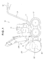
- a self-propelled snow removing machine 10 includes a body frame 11 mounted with a crawler 12.
- the operating handle 13 has two end portions which are bifurcated in leftward and rightward directions with respect to a traveling direction of the snow removing machine, with respective end portions having grips 14, 14.
- An engine 15, which serves as a prime mover, is mounted on the body frame 11.
- the drive shaft 16 is drivably connected to an auger transmission 18 which incorporates therein an over load protection device and is also drivably connected to a blower 21.
- An auger 23 is mounted on an auger shaft 22 of the auger transmission 18.
- the snow removing machine 10 operates such that the drive shaft 16 is driven with the engine 15 to rotate the blower 21 while rotating the auger 23, which is located forwardly of the blower 21, via the auger transmission 18 for thereby lifting up a collected amount of snow, gathered by the auger 23, and discharging it in a remotest location via the shooter 24.
- the drive shaft 16 and the auger transmission 18 constitute a power transmission mechanism to allow power output produced by the engine 15 to be transmitted to the auger 23.
- auger transmission 18 which forms an essential component part of the power transmission mechanism, is discussed in greater detail hereinbelow with respect to FIG. 2.
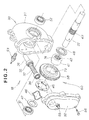
- FIG. 2 is an exploded perspective view of the auger transmission incorporating the overload protecting device.
- the auger transmission 18 is constructed of a worm gear reduction unit.
- the auger transmission 18 includes a transmission case 33 constructed of a case body 31 and case cover 32.
- An input shaft 36 which is connected to the drive shaft 16 shown in FIG. 1, is rotatably supported with the transmission case 33 by means of bearings 34, 35, with the input shaft 36 being formed with a worm 37 which meshes with a worm wheel 38.
- An inner circumferential periphery of the worm wheel 38 is held in engagement with an outer periphery of a boss member 41 in the form of a cylindrical member.
- the boss segment 41 has an inner spline 42, and the auger shaft 22 has an outer spline 43, with the auger shaft 22 and the boss member 41 being coupled to one another through a spline connection.
- a disk-shaped slide washer 45 is located in close proximity to the worm wheel 38.
- a waved leaf spring 46 which serves as an urging member, urges the slide washer 45 toward the worm wheel 38.
- a first washer 47 is located at a position outward of the waved leaf spring 46.
- a second washer 48 is located at a position outward of the boss segment 41.
- the auger shaft 22 is rotatably supported with the case body 31 by means of bearings 51, 52.
- a washer detection switch 53 serves as a detecting means for detecting a sidewise movement of the slide washer 45.
- Reference numeral 55 designates a bolt which closes a pouring bore for allowing oil to be poured into the transmission case 33.
- the case body 31 and the case cover 32 are fixedly coupled to one another by means of a plurality of bolts 56 (with only one of which is shown in FIG. 2).
- overload protection mechanism 60 which is constructed of the worm wheel 38, the boss segment 41, the slide washer 45, the waved leaf spring 46, the first washer 47, the second washer 48 and the washer detection switch 53.
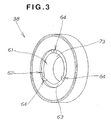
- FIG. 3 shows, in enlarged and perspective view, the worm wheel 38 shown in FIG. 2.
- the worm wheel 38 has an engagement bore 61 with which the boss member 41, which is shown in FIG. 2, engages.
- One of the side walls of the worm wheel 38 is formed with an annular recess adjacent a circumferential periphery of the engagement bore 61.
- a bottom wall portion 63 of the annular recess 62 is formed with a plurality of circumferentially spaced, wheel-side protruding segments 64 in the form of V-shaped profile.
- FIG. 4 shows, in enlarged and perspective view, the slide washer 45.
- the slide washer 45 has one side 66 formed with a plurality of circumferentially spaced wheel-side projections 67, which extends toward the worm wheel 38 (see FIG. 3), and the other side 68 formed with a plurality of circumferentially spaced, case-side projections 71 which extends toward the case body 31. Respective edges of the wheel-side projections 67 and the case-side projections 71 are oriented in a clockwise rotational direction of the auger shaft 22 (see FIG. 1).
- An inner circumferential periphery of the slide washer 45 has an inwardly extending radial projection 88.
- FIGS. 5A and 5B show the waved leaf spring 46 shown in FIG. 2.
- the waved leaf spring 46 is composed of an annular resilient body as viewed in FIG. 5A which is a front view of the same, and is made of a thin sheet formed in a wave-shaped profile by bending process as viewed in FIG. 5B which is a side view of the same. That is, the waved leaf spring 46 has a wave-shaped bent configuration which is bent along a circumferential direction such that the waved leaf spring 46 has bent areas A, which protrude in a front direction relative to the plane of the drawing, and bent areas B, which protrude in a rear direction relative to the plane of the drawing.
- FIGS. 6 and 7 show, in cross section, the auger transmission equipped with the overload protection device.
- press fitting the boss member 41 into the worm wheel 38 renders the worm wheel 38 to rotate with the boss member 41 as far as a normal torque is transmitted, but when the auger shaft 22 encounters a torque exceeding a given value (i.e., an overload condition), the boss member 41 and the worm wheel 38 are brought out of driving engagement to freely rotate relative to one another.
- a given value i.e., an overload condition
- a sulphurizing treatment is applied to both a contact surface 73 and a contact surface 74 of the worm wheel 38 and the boss segment 41, respectively, which constitute the overload protection device 60.
- the sulphurizing treatment is one of metal surface treatment processes which allow sulphuric free radicals to be dispersed in the surface layer of iron materials (such as carbon steel, cast iron, cast steel and stainless steel, etc.). Since the sulphuric free radicals provides an increased lubricating properties, it is highly effective to reduce the wear at the mutually facing contact surfaces of two components due to sliding friction thereof, resulting in an increased wear-resistance property.
- the contact surface 73 of the worm wheel 38 and the contact surface 74 of the boss segment 41 may be treated not only with the sulphurizing process but also with a curburizing process or with a combination of the curburizing process and the sulphurizing process.
- the waved leaf spring 46 is made of an annular thin sheet formed in a waved profile by a bending process and has an advanced feature, when compared with a coil spring etc, in that a space for receiving the spring is reduced to a minimum value to allow the auger transmission 18 to be constructed in a miniaturized size.
- the second washer 48 In order to receive a thrust load applied from the worm wheel 38 and the boss member 41, the second washer 48 has a greater thickness than the first washer 47.
- the washer detection switch 53 is threaded to the case body 31 and has its inner distal end provided with a movable element 76 which detects the sidewise movement (i.e., the movement in a leftward direction as viewed in FIG. 6) of the slide washer 45.
- a movable element 76 which detects the sidewise movement (i.e., the movement in a leftward direction as viewed in FIG. 6) of the slide washer 45.
- Reference numeral 78 designates the case-side protruding element formed at a rear side of a bearing support section 81 of the case body 31 and constitutes a part of the overload protection device 60.
- Reference numerals 82, 83 designate oil seals, respectively, and reference numeral 85 designates a cap for the case body 31.
- the boss member 41 has an outer periphery formed with a cutout 87.
- the cutout 87 receives the inwardly extending radial projection 88 of the slide washer 45, thereby restricting the rotational movement of the slide washer 45 within a rotational angle of ⁇ degrees.
- the slide washer 45 is located at the rear side of the worm wheel 38, contours of the slide washer are traced in a solid line for convenience's sake.
- an advanced feature of the illustrated embodiment concerns the slide washer 45 of which wheel-side projections 67 and the case-side projections 71 are oriented in the same clockwise-rotational direction of the auger shaft 22.
- the slide washer 45 since the wheel-side projections 67 and the case-side projections 71 are oriented in the same rotational direction of the auger shaft 22, erroneous mounting work for the slide washer 45 is effectively avoided.
- the presence of the wheel-side projections 67 and the case-side projections 71, both of which are oriented in the same direction allows the slide washer 45 to be fabricated in an easy fashion.
- respective views (a) indicate the relationship among the worm wheel 38, the boss member 41 and the slide washer 45
- respective views (b) indicate, in enlarged cross sectional views taken on line b-b of respective views (a), the relationship among the case body 31, the washer detection switch 53, the slide washer 45 and the worm wheel 38.
- the boss member 41 is brought into a locked condition within the auger transmission as seen in FIG. 9A.
- the power output of the engine is transmitted to the worm wheel 38 via the drive shaft and the input shaft of the auger transmission, causing the worm wheel 38 to begin its rotation relative to the boss member 41 which remains in the locked condition. That is, as shown in FIG. 9A(a), the worm wheel 38 is rotated counterclockwise as shown by an arrow, and as seen in the view (b), the worm wheel 38 is shifted upward as shown by an arrow.
- the slide washer 45 also rotates in the same direction as the worm wheel 38.
- the washer detection switch 53 remains in its turned-off state, with a resultant difficulty encountered in start-up of the engine. To avoid this inconvenience, it is required for the coupled condition between the wheel-side projection 67 of the slide washer 45 and the wheel-side protruding segments of the worm wheel 38 from being released. An operating process for releasing such a coupling state is described below in detail.
- the auger is manually rotated in the clockwise direction followed by a unitary rotation of the boss member 41, the slide washer 45 and the worm wheel 38 via the auger shaft as shown in FIG. 9E until the case-sided projection 71 of the slide washer 45 is brought into abutting engagement with the case-sided projection 78 of the case body 31.
- an advanced feature of the present invention concerns the case-side protruding element 78 formed on the transmission case 33 of the auger transmission 18, with the rear wall (the other surface) 68 of the slide washer 45 with its front wall 66 formed with the wheel-side projection 67 being held in abutting engagement with the case-side protruding element 78 for restricting the rotational movement of the slide washer 45 relative to the transmission case 33.
- the slide washer 45 is shifted toward the side thereof to its original location, thereby enabling the washer detection switch 53 from being released from a detective position to restart the operation of the engine 15 (see FIG. 1). Accordingly, it is possible for the wheel-side projection 67 of the slide washer 45 to be prevented from remaining in the running-on state over the wheel-side protruding segments 64 with a simplified structure in an easy manner.
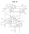
- FIG. 10 is an electric circuit diagram for the overload protecting mechanism of the first preferred embodiment discussed above and serving as means for interrupting the operation of the engine.
- the electric circuit includes a battery 101, a fuse 102, a main switch 103, an ignition coil 104, an ignition plug 105, a starter switch 106, a solenoid 107 for turning on or turning off the starter switch 106, a starter motor 108, relays 111 to 114 and an indicator lamp 115.
- the main switch 103 includes a movable contact 103a, and four stationary contacts 103b, 103c, 103d, 103e.
- the ignition coil 104 functions to generate high voltage power output responsive to power output generated by an alternator (not shown) due to cranking operation of the engine. Upon receiving the high voltage generated by the ignition coil 104, the ignition plug 105 produces an electrical spark.
- the starter switch 106 includes a movable contact 106a, and two stationary contacts 106b, 106c.
- the relay 111 includes a movable contact 111a, and two stationary contacts 111b, 111c.
- the relay 112 includes a movable contact 112a, and two stationary contacts 112b, 112c.
- the relay 113 includes a movable contact 113a, and two stationary contacts 113b, 113c.
- the relay 114 includes a movable contact 114a, and two stationary contacts 114b, 114c.
- the relays 111, 112 constitute an engine stopper means 120 which serves as a prime mover stopper means which forcibly interrupts the operation of the engine during its operation when the washer detection switch 53 is turned on.
- the engine stopper means 120 forms a part of the overload protecting mechanism 60 (see FIG. 6).
- the main switch 103 is first turned on to start up the engine. Upon turning on of the main switch 103, the movable contact 103a is connected to the stationary contacts 103b, 103c, thereby energizing the relay 113. Upon actuation of the relay 113, the connection of the movable contact 113a is changed over from the stationary contact 113b to the stationary contact 113c.
- the relay 111 is energized to allow the connection of the movable contact 111a, which has been connected to the stationary contact 111b as shown in FIG. 11, to be changed over to and to be connected to the stationary contact 111c.
- the solenoid 103 is energized, and the movable contact 111a of the starter switch 106 renders the connection between the stationary contact 106b and the stationary contact 106c to rotate the starter motor 108 by which the engine is cranked and started up.
- the movable switch 103a of the main switch 103 restore its original position to interrupt the connection with respect to the stationary contact 103c while maintaining the connection with only the stationary contact 103b. Consequently, the supply of power output to the solenoid 107 from the battery 101 is interrupted to allow the solenoid 107 to restore its original state such that the connection between the stationary contacts 106b, 106c of the starter switch 106 is interrupted to maintain the operation of the engine under a condition where the starter motor 108 is turned off.
- the main switch 103 may be simply turned off. However, this may leave a flywheel in continued rotation by inertia, thereby causing the ignition plug 105 to produce an electric spark by electric power generated by a generator. Thus, as the main switch 103 is turned off, the ignition plug 105 is grounded by connecting the stationary contact 103d with the stationary contact 103e to prevent electric current flowing to the ignition plug to thereby stop the engine instantly.
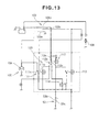
- the washer detection switch 53 is turned on in a manner as previously discussed above with respect to FIG. 9D, i.e., when the movable contact 53a of the washer detection switch 53 is connected to the stationary contact 53b as shown in FIG. 13, then the relay 112 is actuated as shown by an arrow, thereby allowing the movable contact 112a to be connected to the stationary contact 112c to turn on the relay 114. Concurrently, the movable contact 112a of the relay 112 is released from the stationary contact 112b, thereby allowing the relay 111 to restore its original state to cause its movable contact 111a to be connected to the stationary contact 111b.
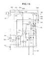
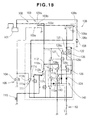
- FIG. 14 is a circuit diagram for illustrating the engine stopper means for the overload protecting device of a second preferred embodiment according to the present invention, with like component parts bearing the same reference numerals as those used with respect the first preferred embodiment shown in FIG. 10 and a detailed description of the same being herein omitted for the sake of simplicity.
- reference numerals 121, 122, 123, 124, 125 designate a diode, respectively.
- Reference numerals 126, 127, 128 designate a relay, respectively.
- the relay 126 to 128 have respective movable contacts 126a to 128a, and respective stationary contacts 126b, 126c, 127b, 127c, 128b, 128c.
- the relays 111, 112, 126 form an engine stopper means 130 which serves as a prime mover stopper means for forcibly stopping the engine during its operation when the washer detection switch 53 is turned on.
- the engine stopper means 130 forms part of the overload protecting device 60 (see FIG. 6). That is, the overload protecting device 60 is constructed of the worm wheel 38, the boss segment 41, the slide washer 45, the waved leaf spring 46, the first washer 47, the second washer 48, the washer detection switch 53, the case-sided projection 78 and the engine stopper means 130.
- the main switch 103 in order to start up the engine, the main switch 103 is turned on, thereby connecting the movable contact 103a to the stationary contacts 103b, 103c.
- electric current flows from the battery 101 to the relay 126 via the fuse 102, the main switch 103 and the diode 121.
- electric current flows through the relay 112 to the indicator lamp 115 which in turn is lighted on.
- the relay 111 is actuated to allow its movable contact 111a to be connected to the stationary contact 111c to allow electric current to flow through the solenoid 107.
- the movable contact 106a of the starter switch 106 is connected to the stationary contacts 106b, 106c to rotate the starter motor 108, rendering the engine to be cranked to cause the ignition plug 105 to produce the ignition spark for starting up the engine.
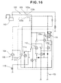
- FIG. 17 is a circuit diagram which is used during the operation of the engine.
- the relay 112 is actuated as shown by an arrow because the relay 126 remains in its self-retained state, causing the movable contact 112a to be connected to the stationary contact 112c.
- the relay 111 restores its original position such that the movable contact 111a is connected to the stationary contact 111b, thereby causing the primary coil of the ignition coil 104 to remain at the low voltage potential to prevent the ignition plug 105 from producing the ignition spark to stop the engine.
- the washer detection switch 53 Under the condition where the washer detection switch 53 is turned on, in the first preferred embodiment shown in FIG. 13, even if the main switch 103 is actuated in its starter start-up position, i.e., even if the movable contact is connected to the stationary contact 103c, the starter motor 108 is not turned on. In the second preferred embodiment, it is to be noted that even when the washer detection switch 53 remains in the turned-on state, the starter motor 108 is enabled to be started up.
- the auger can be manually rotated in a manner as discussed above with respect to FIGS. 9E and 9F, and after start-up of the engine the auger automatically begins to rotate.
- the washer detection switch 53 when the washer detection switch 53 is turned on to flow electric current in a direction as shown by an arrow indicated by a phantom line, the movable contact 112a of the relay 112 is connected to the stationary contact 112c.
- the movable contact 111a of the relay 111 is maintained in electrical connection with the stationary contact 111b, and the engine operation is stopped while turning off the indicator lamp 115.
- the starter motor 108 is not turned on, and the ignition plug 105 does not produce the electrical spark.
- the relay 126 remains in its self-retained state, and the relay 128 is turned on via the diode 122 such that the movable contact 128a is connected to the stationary contact 128c. Then, the relay 113 is turned on and the movable contact 113a is connected to the stationary contact 113c. When this occurs, the relay 112 restores its original state, and the movable contact 112a is connected to the stationary contact 112b, allowing electric current to flow through the indicator lamp 115 which in turn is lighted on. Concurrently, therelay 111 is turned on, and the movable contact 111a is connected to the stationary contact 111c.
- the aforementioned relays 113, 128 constitute a starter restart-up means 140.
- the movable contact 112a of the relay 112 is connected to the stationary contact 112b, thereby energizing the relay 111 such that the movable contact 111a is connected to the stationary contact 111c to cause the ignition plug 105 to produce the ignition spark.
- the relay 128 When connecting the movable contact 103a of the main switch 103 to the stationary contact 103c under the condition where the washer detection switch 53 is turned on, the relay 128 remains in its self-retained state (i.e., the movable contact 128a is held in electrical connection with the stationary contact 128c), thereby playing a role to disenable the circuit for stopping the engine.
- the washer detection switch 53 is turned off to release the self-retained condition of the relay 128, the engine stopper circuit is enabled to function such that when the washer detection switch 53 is turned on, the engine is enabled to be stopped in operation.
- the presence of the starter restart-up means 140 enables the starter motor 108 to start up the engine even when the washer detection switch 53 is turned on.
- it is hardly to restart up the engine when the washer detection switch 53 is turned on, and, as discussed above with respect to FIG. 9F, it is required to take a motion to turn off the washer detection switch 53 by manually releasing the state wherein the wheel-sided projection 67 of the slide washer 45 rides on the wheel-sided projection 64 of the worm wheel 38.
- the maneuverability of the snow removing machine is highly improved.
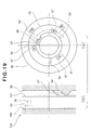
- FIG. 19 is a view for illustrating an auger transmission suited for an overload protecting device of a third preferred embodiment of the present invention, with like component parts bearing the same reference numerals as those used with reference to the first and second preferred embodiments and a detailed description of the like parts being herein omitted for the sake of simplicity.
- FIG. 19(a) is a side view of a disk-shaped slide washer 151 (of which detailed description will be described later) and the washer detection switch 53.
- FIG. 19(b) is a cross sectional view, taken on line E-E of FIG. 19(a), for illustrating a case body 153, the washer detection switch 53, the slide washer 151 and the worm wheel 38.
- the slide washer 151 is designed not to have all of the case-side projections 71 of the slide washer 45 shown in FIG. 4.
- the auger transmission 152 includes a case body 153, of a structure corresponding to that the case-side protruding element 78 is removed from the case body 31 of the auger transmission 18 shown in FIG. 6, and the same remaining component parts as the auger transmission 18 except for the case body 153. That is, the overload protecting device 155, of the third preferred embodiment shown in FIG. 20, has a structure corresponding to that the case-side protruding element78 and the case-side projection 71 of the slide washer 45 are removed from the overload protecting device 60 of the first preferred embodiment shown in FIG. 6.
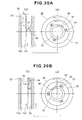
- FIGS. 20A and 20B are views for illustrating the operation of the auger transmission for the overload protecting device shown in FIG. 19.
- both the worm wheel 38 and the slide washer 151 rotate clockwise in the same direction as shown by an arrow relative to the boss segment 41.
- the wheel-side projection 67 slides on the wheel-side protruding segments 64 as viewed in FIG. 20B, and the slide washer 151 is shifted toward the left side thereof.
- the movable element 76 of the washer detection switch 53 is moved for a distance S, resulting on the turning on of the washer detection switch 53.
- the ignition plug is disenabled as previously described above, thereby stopping the engine operation.
- the slide washer 151 continues its rotation together with the worm wheel 38 without being immediately stopped. For this reason, when the inwardly extending radial projection 88 of the slide washer 151 is brought into abutting engagement with the end wall of the cutout 87 of the boss member 41, the rotation of the slide washer 151 is disenabled relative to the boss member 41.
- the wheel-side projection 67 slides across the wheel-side protruding segments 64 as seen in FIG. 20B such that the slide washer 151 is shifted rightward as shown by an arrow in FIG. 20B(a) to be released from the washer detection switch 53 which is consequently is turned off. With such a movement, when the power transmission mechanism of the snow removing machines encounters an overload, it is possible to overcome inconvenience caused by re-turning on of the washer detection switch 53.
- the auger transmission 152 (see FIG. 19) of the third preferred embodiment is designed in a configuration corresponding to the structure wherein the case-sided projections 71 of the slide washer 45 and the case-side protruding element 78 of the case body 31 are dispensed with in the auger transmission 18 of the first preferred embodiment and that slide washer 151 and the case body 153 of the auger transmission 152 of the third preferred embodiment shown in FIG. 19 can be manufactured at a lower cost than those of the auger transmission 18 of the first preferred embodiment.
- prime mover stopper means of the present invention has been shown and described as including relays, the present invention is not limited thereto and may include a control means composed of a computer responsive to a turn-on signal produced by a suitable detecting means for thereby interrupting the electric circuitry coupled to the ignition path.
- the resilient member may not be limited to the waved leaf spring but may be composed of a dish-shaped spring.
- An overload protecting device (60) assembled in an auger transmission (18) is disclosed as including a worm wheel (38) having its side wall formed with a plurality of wheel-side protruding segments (64), a boss member (41) engaging with the wheel and fixedly coupled to an auger shaft (22) for non-rotating relationship, and a slide washer (45) having a plurality of wheel-side projections (67) facing the wheel-side protruding segments.
- a worm wheel having its side wall formed with a plurality of wheel-side protruding segments (64), a boss member (41) engaging with the wheel and fixedly coupled to an auger shaft (22) for non-rotating relationship
- a slide washer (45) having a plurality of wheel-side projections (67) facing the wheel-side protruding segments.
Landscapes
- Engineering & Computer Science (AREA)
- General Engineering & Computer Science (AREA)
- Mechanical Engineering (AREA)
- Architecture (AREA)
- Civil Engineering (AREA)
- Structural Engineering (AREA)
- Transmission Devices (AREA)
- Arrangement Or Mounting Of Propulsion Units For Vehicles (AREA)
- Cleaning Of Streets, Tracks, Or Beaches (AREA)
- Connection Of Motors, Electrical Generators, Mechanical Devices, And The Like (AREA)
Abstract
Description
Claims (4)
- An overload protecting device (60) assembled in an auger transmission (18) of a snow removing machine (10), the device comprising:a worm wheel (38) meshing with a worm (37) formed on an input shaft (36) of the auger transmission;a cylindrical member (34) engaging with the worm wheel to be rotatable relative thereto and fixedly coupled to an auger shaft (22) for non-rotational relationship;a disk (45) located adjacent to the worm wheel for restricting a rotating angle of the cylindrical member and having a plurality of wheel-sided projections (67) facing a plurality of wheel-side protruding segments (64) formed at a side wall of the worm wheel;detecting means (53) for detecting movement of the disk toward a side thereof when the wheel-side projections ride on the wheel side protruding segments responsive to rotation of the worm wheel and the cylindrical member relative to one another;prime mover stopper means (111, 112) for forcibly stopping operation of a prime mover (15) responsive to a signal delivered from the detecting means; anda resilient member (46) urging the disk against the worm wheel,whereby a power transmission path between the prime mover (15) and the auger shaft (22) is prevented from encountering an overload.
- The overload protecting device of claim 1, wherein the auger transmission (18) includes a case (33) formed with case-side protruding element (78), and wherein the disk (45) further has a plurality of case-side projections (71), formed on a rear side opposed to a front surface formed with the wheel-side projections (67), which are brought into abutting engagement with the case-side protruding element to restrict the rotation of the disk relative to the case.
- The overload protecting device of claim 2, wherein the wheel-side projections (67) and the case-side projections (71) are oriented in a clockwise rotational direction of the auger shaft (22).
- The overload protecting device of claim 1, wherein the resilient member (46) includes a waved leaf spring made of an annular thin sheet formed by a wave-forming process.
Applications Claiming Priority (4)
| Application Number | Priority Date | Filing Date | Title |
|---|---|---|---|
| JP2000232424 | 2000-07-31 | ||
| JP2000232424 | 2000-07-31 | ||
| JP2001121466A JP3771458B2 (en) | 2000-07-31 | 2001-04-19 | Snowplow overload prevention device |
| JP2001121466 | 2001-04-19 |
Publications (3)
| Publication Number | Publication Date |
|---|---|
| EP1186716A2 true EP1186716A2 (en) | 2002-03-13 |
| EP1186716A3 EP1186716A3 (en) | 2002-12-11 |
| EP1186716B1 EP1186716B1 (en) | 2004-08-18 |
Family
ID=26597115
Family Applications (1)
| Application Number | Title | Priority Date | Filing Date |
|---|---|---|---|
| EP01117971A Expired - Lifetime EP1186716B1 (en) | 2000-07-31 | 2001-07-24 | Overload protecting device for snow removing machine |
Country Status (6)
| Country | Link |
|---|---|
| US (1) | US6523283B2 (en) |
| EP (1) | EP1186716B1 (en) |
| JP (1) | JP3771458B2 (en) |
| CA (1) | CA2354041C (en) |
| DE (1) | DE60104953T2 (en) |
| NO (1) | NO333967B1 (en) |
Cited By (2)
| Publication number | Priority date | Publication date | Assignee | Title |
|---|---|---|---|---|
| US7096608B2 (en) | 2002-09-13 | 2006-08-29 | Honda Giken Kogyo Kabushiki Kaisha | Overload prevention device for a snow removing machine |
| CN106702942A (en) * | 2016-12-16 | 2017-05-24 | 中国重汽集团柳州运力科迪亚克机械有限责任公司 | Snow thrower auger overload protection device |
Families Citing this family (11)
| Publication number | Priority date | Publication date | Assignee | Title |
|---|---|---|---|---|
| JP3771458B2 (en) * | 2000-07-31 | 2006-04-26 | 本田技研工業株式会社 | Snowplow overload prevention device |
| US7322745B2 (en) * | 2002-07-23 | 2008-01-29 | Rapiscan Security Products, Inc. | Single boom cargo scanning system |
| US6971277B2 (en) * | 2002-08-07 | 2005-12-06 | Hub City Inc. | Gear drive casing apparatus for enclosing a gear drive |
| WO2008086139A2 (en) * | 2007-01-04 | 2008-07-17 | Johnson Controls Technology Company | Transmission for motorized track system |
| DE102007032412B4 (en) * | 2007-07-12 | 2010-01-28 | Nordex Energy Gmbh | Device for detecting the slipping path of a slip clutch in a wind turbine |
| RU2530916C1 (en) * | 2013-02-26 | 2014-10-20 | Федеральное государственное бюджетное образовательное учреждение высшего профессионального образования "Чувашская государственная сельскохозяйственная академия" | Device for processing of surface of road pavings |
| US10791662B2 (en) * | 2017-05-19 | 2020-10-06 | Kai S. Lee | Twin shaft gardening system |
| US10780930B1 (en) | 2018-02-20 | 2020-09-22 | Zoox, Inc. | Worm gear drive unit interface and assembly methods |
| US10960939B1 (en) * | 2018-02-20 | 2021-03-30 | Zoox, Inc. | Worm gear drive unit interface and assembly methods |
| EP3924220B1 (en) * | 2019-03-26 | 2023-08-02 | Magna Exteriors Inc. | Rotatable box step |
| JP2022074519A (en) | 2020-11-04 | 2022-05-18 | 本田技研工業株式会社 | Working machine |
Family Cites Families (19)
| Publication number | Priority date | Publication date | Assignee | Title |
|---|---|---|---|---|
| US3313049A (en) * | 1964-03-05 | 1967-04-11 | Hahn Inc | Overload limiter for snow blowers |
| JPS5134111A (en) | 1974-09-17 | 1976-03-23 | Mitsubishi Petrochemical Co | |
| AU508665B2 (en) * | 1977-02-08 | 1980-03-27 | Eaton Corporation | Four-wheel drive vehicle with Drive Transfer Gear Assembly |
| JP2563979B2 (en) * | 1988-06-23 | 1996-12-18 | ヤマハ発動機株式会社 | Work machine power transmission device |
| JPH02183003A (en) * | 1989-01-06 | 1990-07-17 | Fuji Heavy Ind Ltd | Device for detecting breakage of auger pin for snow remover |
| US5398431A (en) * | 1990-01-19 | 1995-03-21 | The Toro Company | Single stage snowthrower impeller |
| US5156244A (en) * | 1990-08-31 | 1992-10-20 | The Aro Corporation | Torque sensing automatic shut-off and reset clutch for screwdrivers, nutsetters and the like |
| US5101911A (en) * | 1991-03-20 | 1992-04-07 | Lee Kai S | Rotor tiller having counter-rotating twin shafts |
| US5545109A (en) * | 1991-05-11 | 1996-08-13 | Hayakawa; Toshio | Torque limiter |
| NL9101335A (en) * | 1991-08-02 | 1993-03-01 | Emerson Electric Co | TRANSMISSION FOR ELECTRICALLY POWERED TOOLS. |
| US5802745A (en) * | 1995-09-15 | 1998-09-08 | Haseotes; Byron | Hydraulic system for a road vehicle |
| JPH10298939A (en) * | 1997-04-25 | 1998-11-10 | Seirei Ind Co Ltd | Power transmission mechanism of snow plow |
| FI3291U1 (en) * | 1997-08-21 | 1998-02-24 | Pertti Johannes Hynoenen | Feed coil for feeding snow to the snow thrower |
| WO1999014439A1 (en) * | 1997-09-15 | 1999-03-25 | Newton Roy Gingerich | Rotary drive contained within hollow rotating drum |
| JP4252692B2 (en) * | 1999-10-05 | 2009-04-08 | 本田技研工業株式会社 | Snowplow overload prevention mechanism |
| JP4202579B2 (en) * | 2000-03-30 | 2008-12-24 | 本田技研工業株式会社 | Power transmission device for snowplow |
| JP4503778B2 (en) * | 2000-03-29 | 2010-07-14 | 本田技研工業株式会社 | snowblower |
| JP3771458B2 (en) * | 2000-07-31 | 2006-04-26 | 本田技研工業株式会社 | Snowplow overload prevention device |
| JP2002115582A (en) * | 2000-10-12 | 2002-04-19 | Mitsubishi Electric Corp | Automatic clutch overheat protection device |
-
2001
- 2001-04-19 JP JP2001121466A patent/JP3771458B2/en not_active Expired - Fee Related
- 2001-07-24 EP EP01117971A patent/EP1186716B1/en not_active Expired - Lifetime
- 2001-07-24 DE DE60104953T patent/DE60104953T2/en not_active Expired - Lifetime
- 2001-07-25 CA CA002354041A patent/CA2354041C/en not_active Expired - Lifetime
- 2001-07-27 US US09/916,524 patent/US6523283B2/en not_active Expired - Lifetime
- 2001-07-27 NO NO20013695A patent/NO333967B1/en not_active IP Right Cessation
Cited By (3)
| Publication number | Priority date | Publication date | Assignee | Title |
|---|---|---|---|---|
| US7096608B2 (en) | 2002-09-13 | 2006-08-29 | Honda Giken Kogyo Kabushiki Kaisha | Overload prevention device for a snow removing machine |
| DE10342023B4 (en) * | 2002-09-13 | 2014-01-16 | Honda Giken Kogyo K.K. | Overload prevention device of a motor-driven snow remover with a reamer |
| CN106702942A (en) * | 2016-12-16 | 2017-05-24 | 中国重汽集团柳州运力科迪亚克机械有限责任公司 | Snow thrower auger overload protection device |
Also Published As
| Publication number | Publication date |
|---|---|
| EP1186716A3 (en) | 2002-12-11 |
| CA2354041C (en) | 2006-05-02 |
| US20020014132A1 (en) | 2002-02-07 |
| US6523283B2 (en) | 2003-02-25 |
| EP1186716B1 (en) | 2004-08-18 |
| NO333967B1 (en) | 2013-11-04 |
| CA2354041A1 (en) | 2002-01-31 |
| JP2002115223A (en) | 2002-04-19 |
| JP3771458B2 (en) | 2006-04-26 |
| DE60104953D1 (en) | 2004-09-23 |
| NO20013695D0 (en) | 2001-07-27 |
| NO20013695L (en) | 2002-02-01 |
| DE60104953T2 (en) | 2005-01-05 |
Similar Documents
| Publication | Publication Date | Title |
|---|---|---|
| EP1186716B1 (en) | Overload protecting device for snow removing machine | |
| DE19963418B4 (en) | Vehicle with an engine stop / start control unit | |
| EP0685783A2 (en) | Power take-off switch means | |
| JP2002264685A (en) | Two-wheel drive four-wheel drive switching control method for rough terrain vehicles | |
| JPH05238411A (en) | Method and device for activating electric power steering for vehicle | |
| US7473207B1 (en) | Transmission shaft rotation sensor switch | |
| CA2177301C (en) | Engine starter system having an improved pinion assembly | |
| KR20050041942A (en) | Starter | |
| US6782770B2 (en) | Starter motor having planetary gear device for reducing rotational speed of electric motor | |
| US7870801B2 (en) | Rotational power transfer device and related manufacturing method | |
| JP4252692B2 (en) | Snowplow overload prevention mechanism | |
| JP2001213288A (en) | Vehicle parking device | |
| FR2831925A1 (en) | Automatic start stop circuit for motor vehicle has clutch and switches to interrupt starter motor drive and cut power after starting | |
| JP3736870B2 (en) | Vehicle parking device | |
| JP3756444B2 (en) | Snowplow overload prevention device | |
| US7096608B2 (en) | Overload prevention device for a snow removing machine | |
| JP3039401B2 (en) | Starter | |
| JPH0114421B2 (en) | ||
| JP3901132B2 (en) | Engine starter | |
| JP4857067B2 (en) | Magnet switch and starter | |
| JP4797301B2 (en) | Shift range switching control device for automatic transmission | |
| JP2604116Y2 (en) | Gap adjustment device | |
| JP4227109B2 (en) | Starter motor with intermediate gear | |
| JP2887067B2 (en) | Automatic Obstacle Sensing and Stopping Device for Snowplow Augers | |
| JPS6339422Y2 (en) |
Legal Events
| Date | Code | Title | Description |
|---|---|---|---|
| PUAI | Public reference made under article 153(3) epc to a published international application that has entered the european phase |
Free format text: ORIGINAL CODE: 0009012 |
|
| AK | Designated contracting states |
Kind code of ref document: A2 Designated state(s): AT BE CH CY DE DK ES FI FR GB GR IE IT LI LU MC NL PT SE TR |
|
| AX | Request for extension of the european patent |
Free format text: AL;LT;LV;MK;RO;SI |
|
| PUAL | Search report despatched |
Free format text: ORIGINAL CODE: 0009013 |
|
| AK | Designated contracting states |
Kind code of ref document: A3 Designated state(s): AT BE CH CY DE DK ES FI FR GB GR IE IT LI LU MC NL PT SE TR |
|
| AX | Request for extension of the european patent |
Free format text: AL;LT;LV;MK;RO;SI |
|
| 17P | Request for examination filed |
Effective date: 20030219 |
|
| 17Q | First examination report despatched |
Effective date: 20030407 |
|
| AKX | Designation fees paid |
Designated state(s): CH DE LI SE |
|
| GRAP | Despatch of communication of intention to grant a patent |
Free format text: ORIGINAL CODE: EPIDOSNIGR1 |
|
| GRAS | Grant fee paid |
Free format text: ORIGINAL CODE: EPIDOSNIGR3 |
|
| GRAA | (expected) grant |
Free format text: ORIGINAL CODE: 0009210 |
|
| AK | Designated contracting states |
Kind code of ref document: B1 Designated state(s): CH DE LI SE |
|
| REG | Reference to a national code |
Ref country code: CH Ref legal event code: EP |
|
| REG | Reference to a national code |
Ref country code: CH Ref legal event code: NV Representative=s name: A. BRAUN, BRAUN, HERITIER, ESCHMANN AG PATENTANWAE |
|
| REG | Reference to a national code |
Ref country code: IE Ref legal event code: FG4D |
|
| REF | Corresponds to: |
Ref document number: 60104953 Country of ref document: DE Date of ref document: 20040923 Kind code of ref document: P |
|
| REG | Reference to a national code |
Ref country code: SE Ref legal event code: TRGR |
|
| PLBE | No opposition filed within time limit |
Free format text: ORIGINAL CODE: 0009261 |
|
| STAA | Information on the status of an ep patent application or granted ep patent |
Free format text: STATUS: NO OPPOSITION FILED WITHIN TIME LIMIT |
|
| 26N | No opposition filed |
Effective date: 20050519 |
|
| REG | Reference to a national code |
Ref country code: CH Ref legal event code: PFA Owner name: HONDA GIKEN KOGYO KABUSHIKI KAISHA Free format text: HONDA GIKEN KOGYO KABUSHIKI KAISHA#1-1, MINAMI-AOYAMA 2-CHOME#MINATO-KU TOKYO (JP) -TRANSFER TO- HONDA GIKEN KOGYO KABUSHIKI KAISHA#1-1, MINAMI-AOYAMA 2-CHOME#MINATO-KU TOKYO (JP) |
|
| REG | Reference to a national code |
Ref country code: CH Ref legal event code: PCAR Free format text: NEW ADDRESS: HOLBEINSTRASSE 36-38, 4051 BASEL (CH) |
|
| PGFP | Annual fee paid to national office [announced via postgrant information from national office to epo] |
Ref country code: SE Payment date: 20190710 Year of fee payment: 19 Ref country code: DE Payment date: 20190710 Year of fee payment: 19 |
|
| REG | Reference to a national code |
Ref country code: DE Ref legal event code: R084 Ref document number: 60104953 Country of ref document: DE |
|
| PGFP | Annual fee paid to national office [announced via postgrant information from national office to epo] |
Ref country code: CH Payment date: 20190718 Year of fee payment: 19 |
|
| REG | Reference to a national code |
Ref country code: DE Ref legal event code: R119 Ref document number: 60104953 Country of ref document: DE |
|
| REG | Reference to a national code |
Ref country code: CH Ref legal event code: PL |
|
| REG | Reference to a national code |
Ref country code: SE Ref legal event code: EUG |
|
| PG25 | Lapsed in a contracting state [announced via postgrant information from national office to epo] |
Ref country code: CH Free format text: LAPSE BECAUSE OF NON-PAYMENT OF DUE FEES Effective date: 20200731 Ref country code: LI Free format text: LAPSE BECAUSE OF NON-PAYMENT OF DUE FEES Effective date: 20200731 |
|
| PG25 | Lapsed in a contracting state [announced via postgrant information from national office to epo] |
Ref country code: DE Free format text: LAPSE BECAUSE OF NON-PAYMENT OF DUE FEES Effective date: 20210202 Ref country code: SE Free format text: LAPSE BECAUSE OF NON-PAYMENT OF DUE FEES Effective date: 20200725 |