EP1186446A2 - Bicycle hub assembly - Google Patents
Bicycle hub assembly Download PDFInfo
- Publication number
- EP1186446A2 EP1186446A2 EP01121256A EP01121256A EP1186446A2 EP 1186446 A2 EP1186446 A2 EP 1186446A2 EP 01121256 A EP01121256 A EP 01121256A EP 01121256 A EP01121256 A EP 01121256A EP 1186446 A2 EP1186446 A2 EP 1186446A2
- Authority
- EP
- European Patent Office
- Prior art keywords
- hub
- spoke
- mounting portion
- assembly
- hub body
- Prior art date
- Legal status (The legal status is an assumption and is not a legal conclusion. Google has not performed a legal analysis and makes no representation as to the accuracy of the status listed.)
- Withdrawn
Links
- 230000000712 assembly Effects 0.000 description 7
- 238000000429 assembly Methods 0.000 description 7
- 230000005540 biological transmission Effects 0.000 description 5
- 239000000463 material Substances 0.000 description 5
- 239000007769 metal material Substances 0.000 description 4
- 210000002445 nipple Anatomy 0.000 description 4
- 230000036961 partial effect Effects 0.000 description 4
- 230000008878 coupling Effects 0.000 description 3
- 238000010168 coupling process Methods 0.000 description 3
- 238000005859 coupling reaction Methods 0.000 description 3
- 229920000049 Carbon (fiber) Polymers 0.000 description 2
- FYYHWMGAXLPEAU-UHFFFAOYSA-N Magnesium Chemical compound [Mg] FYYHWMGAXLPEAU-UHFFFAOYSA-N 0.000 description 2
- 229910000831 Steel Inorganic materials 0.000 description 2
- RTAQQCXQSZGOHL-UHFFFAOYSA-N Titanium Chemical compound [Ti] RTAQQCXQSZGOHL-UHFFFAOYSA-N 0.000 description 2
- 229910052782 aluminium Inorganic materials 0.000 description 2
- XAGFODPZIPBFFR-UHFFFAOYSA-N aluminium Chemical compound [Al] XAGFODPZIPBFFR-UHFFFAOYSA-N 0.000 description 2
- 239000004917 carbon fiber Substances 0.000 description 2
- 239000002131 composite material Substances 0.000 description 2
- 229910052749 magnesium Inorganic materials 0.000 description 2
- 239000011777 magnesium Substances 0.000 description 2
- VNWKTOKETHGBQD-UHFFFAOYSA-N methane Chemical compound C VNWKTOKETHGBQD-UHFFFAOYSA-N 0.000 description 2
- 230000002787 reinforcement Effects 0.000 description 2
- 229910001220 stainless steel Inorganic materials 0.000 description 2
- 239000010935 stainless steel Substances 0.000 description 2
- 239000010959 steel Substances 0.000 description 2
- 229910052719 titanium Inorganic materials 0.000 description 2
- 239000010936 titanium Substances 0.000 description 2
- 244000268528 Platanus occidentalis Species 0.000 description 1
- 239000000919 ceramic Substances 0.000 description 1
- 230000002860 competitive effect Effects 0.000 description 1
- 238000004519 manufacturing process Methods 0.000 description 1
- 238000000034 method Methods 0.000 description 1
- 238000012986 modification Methods 0.000 description 1
- 230000004048 modification Effects 0.000 description 1
- 230000002093 peripheral effect Effects 0.000 description 1
- 239000004033 plastic Substances 0.000 description 1
- 230000000717 retained effect Effects 0.000 description 1
- 125000006850 spacer group Chemical group 0.000 description 1
Images




Classifications
-
- B—PERFORMING OPERATIONS; TRANSPORTING
- B60—VEHICLES IN GENERAL
- B60B—VEHICLE WHEELS; CASTORS; AXLES FOR WHEELS OR CASTORS; INCREASING WHEEL ADHESION
- B60B1/00—Spoked wheels; Spokes thereof
- B60B1/02—Wheels with wire or other tension spokes
- B60B1/0215—Wheels with wire or other tension spokes characterised by specific grouping of spokes
-
- B—PERFORMING OPERATIONS; TRANSPORTING
- B60—VEHICLES IN GENERAL
- B60B—VEHICLE WHEELS; CASTORS; AXLES FOR WHEELS OR CASTORS; INCREASING WHEEL ADHESION
- B60B1/00—Spoked wheels; Spokes thereof
- B60B1/02—Wheels with wire or other tension spokes
- B60B1/04—Attaching spokes to rim or hub
- B60B1/041—Attaching spokes to rim or hub of bicycle wheels
-
- B—PERFORMING OPERATIONS; TRANSPORTING
- B60—VEHICLES IN GENERAL
- B60B—VEHICLE WHEELS; CASTORS; AXLES FOR WHEELS OR CASTORS; INCREASING WHEEL ADHESION
- B60B1/00—Spoked wheels; Spokes thereof
- B60B1/02—Wheels with wire or other tension spokes
- B60B1/04—Attaching spokes to rim or hub
- B60B1/042—Attaching spokes to hub
-
- B—PERFORMING OPERATIONS; TRANSPORTING
- B60—VEHICLES IN GENERAL
- B60B—VEHICLE WHEELS; CASTORS; AXLES FOR WHEELS OR CASTORS; INCREASING WHEEL ADHESION
- B60B27/00—Hubs
- B60B27/0005—Hubs with ball bearings
-
- B—PERFORMING OPERATIONS; TRANSPORTING
- B60—VEHICLES IN GENERAL
- B60B—VEHICLE WHEELS; CASTORS; AXLES FOR WHEELS OR CASTORS; INCREASING WHEEL ADHESION
- B60B27/00—Hubs
- B60B27/0078—Hubs characterised by the fixation of bearings
-
- B—PERFORMING OPERATIONS; TRANSPORTING
- B60—VEHICLES IN GENERAL
- B60B—VEHICLE WHEELS; CASTORS; AXLES FOR WHEELS OR CASTORS; INCREASING WHEEL ADHESION
- B60B27/00—Hubs
- B60B27/02—Hubs adapted to be rotatably arranged on axle
- B60B27/023—Hubs adapted to be rotatably arranged on axle specially adapted for bicycles
- B60B27/026—Hubs adapted to be rotatably arranged on axle specially adapted for bicycles comprising quick release devices
-
- B—PERFORMING OPERATIONS; TRANSPORTING
- B60—VEHICLES IN GENERAL
- B60B—VEHICLE WHEELS; CASTORS; AXLES FOR WHEELS OR CASTORS; INCREASING WHEEL ADHESION
- B60B27/00—Hubs
- B60B27/02—Hubs adapted to be rotatably arranged on axle
- B60B27/04—Hubs adapted to be rotatably arranged on axle housing driving means, e.g. sprockets
- B60B27/047—Hubs adapted to be rotatably arranged on axle housing driving means, e.g. sprockets comprising a freewheel mechanisms
-
- B—PERFORMING OPERATIONS; TRANSPORTING
- B62—LAND VEHICLES FOR TRAVELLING OTHERWISE THAN ON RAILS
- B62M—RIDER PROPULSION OF WHEELED VEHICLES OR SLEDGES; POWERED PROPULSION OF SLEDGES OR SINGLE-TRACK CYCLES; TRANSMISSIONS SPECIALLY ADAPTED FOR SUCH VEHICLES
- B62M9/00—Transmissions characterised by use of an endless chain, belt, or the like
- B62M9/04—Transmissions characterised by use of an endless chain, belt, or the like of changeable ratio
- B62M9/06—Transmissions characterised by use of an endless chain, belt, or the like of changeable ratio using a single chain, belt, or the like
- B62M9/10—Transmissions characterised by use of an endless chain, belt, or the like of changeable ratio using a single chain, belt, or the like involving different-sized wheels, e.g. rear sprocket chain wheels selectively engaged by the chain, belt, or the like
Definitions
- This invention generally relates to a bicycle wheel having a hub axle adapted to be mounted to a bicycle frame, a hub body rotatably supported on the hub shaft, an annular rim and a plurality of spokes extending inwardly from the rim to the hub body. More specifically, the present invention relates to the hub of the bicycle wheel with a freewheel being provided axially on one side of the hub body.
- Bicycling is becoming an increasingly more popular form of recreation as well as a means of transportation. Moreover, bicycling has also become a very popular competitive sport for both amateurs and professionals. Whether the bicycle is used for recreation, transportation or competition, the bicycle industry is constantly improving the various components of the bicycle.
- One particular component of the bicycle that has been extensively redesigned over the past years is the rear bicycle hubs.
- Rear bicycle hubs are constantly being redesigned to be lightweight yet more durable and stronger.
- rear bicycle hubs have been redesigned over the years to have more sprockets or gears. In particular, most of today's bicycles have at least seven sprockets. Moreover, some bicycles even have nine sprockets. There are demands for a simplified mounting structure and easy mounting method.
- One popular form of drive train for a bicycle includes utilizing a plurality of sprockets that are mounted on the hub of the rear bicycle wheel. During pedaling, the bicycle chain engages one of the rear sprockets to rotate the rear wheel. When bicycle rider stops pedaling, the rear wheel should be able to continue to rotate while the sprockets remain stationary. Accordingly, the rear hub is provided with a freewheel that has a one-way clutch.
- Freewheels are usually mounted on the rear hub of a bicycle for transmitting a driving force to the rear bicycle wheel in one rotation direction only. Freewheels are used so that the bicycle can advance freely without any rotation of the pedals. Freewheels include boss type freewheels which are mounted on the boss of the rear hub by being screwed onto the rear hub, and freehub type freewheels which are fastened to the rear hub as integral parts of the rear hub.
- Both types of freewheels are equipped with an outer tubular part, an inner tubular part which is installed radially inwardly of the outer tubular part so that the inner tubular part is free to rotate relative to the outer cylinder part, and a one-way clutch which is installed between the outer tubular part and inner tubular part for transmitting the driving force from the outer tubular part to the inner tubular part in one rotational direction only.
- the outer tubular part has a plurality of gears mounted thereon, while the inner tubular part is usually mounted on the rear hub of the bicycle.
- the boss is formed as an outer race of a one-way clutch, and the one-way clutch and inner race are disposed on an inner periphery of the boss.
- One object of the present invention is to provide a rear hub assembly for a bicycle wheel that is more stable and more rigid relative to conventional rear hub assemblies with an equal number of gears or sprockets.
- Another object of the present invention is to provide a rear hub assembly for a bicycle wheel that has better performance in terms of strength and durability relative to conventional rear hub assemblies.
- Still another object of the present invention is to provide a rear hub assembly with a freewheel that can support several sprockets in a compact manner.
- Yet another object of the present invention is to provide a freewheel that is relatively easy to assemble and relatively inexpensive to manufacture.
- a bicycle wheel basically having central hub assembly, a plurality of spokes extending outwardly from the central hub assembly and an annular rim coupled to the outer ends of the spokes for supporting a tire.
- the central hub assembly has a hub axle, a hub unit, a freewheel and a plurality of sprockets.
- the hub axle has a center axis extending between a first frame mounting end and a second frame mounting end.
- the hub unit has a hub body, a first spoke mounting portion, a second spoke mounting portion and an interior passageway.
- the first spoke mounting portion is located adjacent a first end of the hub body.
- the second spoke mounting portion is located adjacent a second end of the hub body.
- the interior passageway extends through the hub body with the hub axle being rotatably supported therein.
- the freewheel is operatively coupled between the first end of the hub axle and the first end of the hub body.
- the sprockets are coupled to the freewheel and axially spaced apart along the freewheel.
- the sprocket assembly has an inner portion recessed within a recess of the first spoke mounting portion.
- a bicycle 10 is illustrated with a bicycle hub assembly 12 in accordance with the present invention.
- the bicycle 10 basically has a frame 14 with front and rear wheels 15 and 16 rotatably coupled thereto.
- a front fork 17 is coupled between the frame 14 and the front wheel 15 in a conventional manner.
- the front wheel 15 is turned by turning a handlebar 18, which is fixedly coupled to the front fork 17.
- the rear wheel 16 is rotatably coupled to a rear portion of the frame 14.
- the frame 14 also has a seat 19 adjustably coupled to frame 14 and a drive train 20 for propelling bicycle 10.
- the rear wheel 16 basically includes the rear bicycle hub assembly 12 of the present invention, a plurality of outwardly extending spokes 24 and an annular rim 26 with a pneumatic tire 28 coupled thereto in a conventional manner.
- the rear wheel 16 has sixteen spokes 24 extending radially between the hub assembly 12 and the annular rim portion 26.
- the rear wheel 16 can have fewer or more spokes 24 than illustrated if needed and/or desired.
- the rim 26 is constructed of a substantially rigid material, such as those materials, which are well known in the art.
- the rim 26 can be constructed of any suitable metallic material, such as plated steel, stainless steel, aluminum, magnesium or titanium, as well as other non-metallic materials, such as a carbon fiber composite, which can be utilized for a bicycle wheel.
- the rim 26 is relatively conventional. Therefore, rim 26 will not be discussed or illustrated in detail herein.
- Each of the spokes 24 has an outer end or spoke head coupled to rim 26 by reinforcement members or washers 29 and an inner threaded end coupled to the rear bicycle hub assembly 12 by spoke nipples 24a and 24b.
- the reinforcement members or washers 29 are designed to disperse the stresses applied to rim 26 by spokes 24.
- the inner ends of spokes 24 are adjustable coupled to the rear bicycle hub assembly 12. More specifically, the inner ends of spokes 24 are threadedly coupled to the rear bicycle hub assembly 12 by spoke nipples 24a and 24b.
- the bicycle hub assembly 12 basically includes a hub axle 30, a hub unit 32, a freewheel 34 and a sprocket assembly 36.
- the hub axle 30 rotatably supports the hub unit 32, the freewheel 34 and the sprocket assembly 36 about a center axis of rotation A by a pair of bearing assemblies 38a and 38b.
- the hub axle 30 has a first frame mounting end 30a and a second frame mounting end 30b with the center axis A extending therebetween.
- the hub axle 30 is also preferably hollow with a quick release mechanism 40 extending therethrough for coupling the rear wheel 16 to the frame 14 in a conventional manner.
- the quick release mechanism 40 has a quick-release hub rod 41 extending through the axial center of the hub axle 30 with an adjusting nut 41a coupled to one end and a quick-release lever 41b coupled to other end.
- the first and second frame mounting ends 30a and 30b of hub axle 30 are threaded to receive a pair of nuts 42a and 42b. Nuts 42a and 42b hold bearing assemblies 38a and 38b, the hub body 50 and the hub axle 30 together when the hub unit 32 is assembled. As mentioned above, the first and second bearing assemblies 38a and 38b rotatably support the hub body 50 on hub axle 30.
- the bearing assembly 38a basically includes a plurality of balls 43a located between an inner race member 44a and an outer race member 45a.
- the bearing assembly 38b basically includes a plurality of balls 46b located between an inner race member 47b and an outer race member 48b. Since bearing assemblies 38a and 38b and are well know in the bicycle art, they will not be discussed or illustrated in detail herein.
- the hub unit 32 basically includes a hub body 50 with a first spoke mounting portion 52a located adjacent a first end of the hub body 50, a second spoke mounting portion 52b located adjacent a second end of the hub body 50 and a center tubular portion 52c extending between the first and second ends of the hub body 50.
- An interior passageway 52d extends through the hub body 50 between the first and second ends of the hub body 50.
- the bearing assemblies 38a and 38b rotatably support the hub axle 30 within the interior passageway 52d.
- the remaining parts of hub unit 32 are relatively conventional, and thus, the remaining parts of hub unit 32 will not be discussed or illustrated in detail herein.
- the hub body 50 is formed as a one-piece, unitary member. It will be apparent to those skilled in the art that the hub body 50 can be constructed of any substantially rigid material, such as those materials, which are known in the art.
- the hub body 50 can be constructed of any suitable metallic material, such as plated steel, stainless steel, aluminum, magnesium or titanium, as well as other non-metallic materials, such as carbon fiber composite, ceramic or plastic.
- the first mounting portion 52a and the second mounting portion 52b could be constructed of different materials from the center tubular portion 52c of the hub body 50 as need and/or desired.
- the first spoke mounting portion 52a extends radially outwardly from the first end of the hub body 50, while second spoke mounting portion 52b extends radially outwardly from the second end of the hub body 50.
- the second mounting portion 52b is different from the first mounting portion 52a in that the freewheel 34 is coupled to the first mounting portion 52a.
- Each spoke mounting portion 52a and 52b has a plurality of spoke openings for coupling a plurality of spokes 24 thereto.
- the first spoke mounting portion 52a has eight spoke openings with four inner spoke openings 55a and four outer spoke openings 56a. Spoke openings 55a and 56a will be referred to herein as the first spoke openings.
- the first spoke mounting portion 52a includes four attachment members 54a extending radially outwardly from the hub body 50 with two of the first spoke openings 55a and 56a formed in each of the attachment members 54a.
- the second spoke mounting portion 52b has eight spoke openings with four inner spoke openings 55b and four outer spoke openings 56b. Spoke openings 55b and 56b will be referred to herein as the second spoke openings.
- the second spoke mounting portion 52b includes four attachment members 54b extending radially outwardly from the hub body 50 with two of the second spoke openings 55b and 56b formed in each of the attachment members 54b.
- the spoke attachment members 54a and 54b protrude in the diametric direction and are provided at four places each on the left and right ends at a distance from each other in the circumferential direction.
- the spoke attachment members 54a and 54b are provided at regular intervals in the circumferential direction, preferably ninety degrees apart from each other.
- the spoke attachment members 54a on the right side and the spoke attachment members 54b on the left side are aligned when view along the center axis A of the hub axle 30.
- spoke attachment members 54a and 54b will depend upon the number of spokes and their shapes. Accordingly, it will be apparent to those skilled in the art from this disclosure that other types and shapes of hubs can be utilized in connection with the present invention.
- the first and second inner spoke openings 55a and 55b have their longitudinal axes B extending tangentially from an inner imaginary circle centered on the center axis A.
- the first and second outer spoke openings 56a and 56b have their longitudinal axes C extending tangentially from an outer imaginary circle centered on the center axis A.
- the spoke openings 55a, 55b and 56a, 56b have longitudinal axes B and C, respectively, extending at an angle to the center plane P c that substantially bisects the rear wheel 16.
- the spokes 24 arranged in the spoke openings 55a, 55b and 56a, 56b such that the spokes 24 extend from the spoke attachment members 54a and 54b and converge towards the center plane P c as they approach the rim 26.
- each of the first and second spoke openings 55a, 56a and 55b, 56b forms a through hole that receives one of the spoke nipples 24a or 24b of spokes 24 therein.
- Each of the first and second spoke openings 55a, 56a and 55b, 56b has a larger diameter portion 58 and a smaller diameter portion 59.
- the spokes 24 exit out of the smaller diameter portions 59 of the first and second spoke openings 55a, 56a and 55b, 56b.
- the "center" of each of the first and second spoke openings 55a, 56a and 55b, 56b as used herein refers to the center opening of the smaller diameter portion 59 where the spoke 24 exits out of the spoke opening.
- the inner spoke openings 55a and 55b and the outer spoke openings 56a and 56b go through the front and rear walls of the left and right spoke attachment members 54a and 54b in the circumferential direction of the hub body 50 at different positions in the radial direction from the center of the hub axle 30, that is, at different positions in the radial direction in the plane that includes the hub axle 30.
- the spoke openings 55a, 56a and 55b, 56b are holes that serve to engage the nipples 24a and 24b of the spokes 24.
- the freewheel 34 is operatively coupled between the first end of the hub axle 30 and the first end of the hub body 50.
- the freewheel 34 is relatively conventional, and thus, will not be discussed or illustrated in detail herein.
- the main difference between the freewheel 34 of the present invention and other freewheels is that freewheel 34 is partially recessed into the first spoke mounting portion 52a.
- the first spoke mounting portion 52a has a recess 53 that is concentric with the interior passageway 52d for receiving an inner portion of the freewheel 34 and an inner portion of the sprocket assembly 36 therein as discussed below.
- the first spoke mounting portion 52a overlaps the inner portion of the freewheel 34 so that the axial spacing between the first and second spoke mounting portions 52a and 52b can be maximized without increase the overall width of the bicycle hub assembly 12.
- the freewheel 34 is coupled to hub body 50 in a conventional manner and has a plurality of splines for receiving the sprocket assembly 36 thereon.
- the freewheel 34 includes of a driving cylinder 60, a driven cylinder 62 having an outer peripheral surface with splines 62a for nonrotatably coupling the sprocket assembly 36 thereto, a unidirectional rotation transmission mechanism (one-way clutch) 66 and two sets of ball bearings 68 and 70 that rotatably support the driven cylinder 62 to the driving cylinder 60.
- the driven cylinder 62 is adapted, by means of the unidirectional rotation transmission mechanism 66 and the ball bearings 68 and 70 to freely rotate in one direction relative to the driving cylinder 60.
- the ball bearings 70 that supports one end side of the driven cylinder 62 are supported by the outer race 45a of bearing assembly38a screwed onto the right-hand end of the driving cylinder 60.
- One end side of the driven cylinder 62 of the freewheel 34 is rotatably supported on the hub shaft 30 through balls 43a and an inner race member 44a screwed onto the hub shaft 30.
- the unidirectional rotation transmission mechanism 66 is so constructed that the driven cylinder 62 is provided with serrated teeth 80 on the inner periphery thereof between the ball bearings 68 and 70.
- the driving cylinder 60 is provided on the outer periphery thereof with transmission pawls 82 as seen in Figure 10.
- the transmission pawls 82 comes into mesh with the serrated teeth 80 upon the positive rotation of the driven cylinder 62 to transmit the driving power thereof to the hub body 50 that is splined engaged with the driving cylinder 60 via the tubular support 84 of the hub body 50.
- the driven cylinder 62 of the freewheel 34 has an outwardly facing abutment surface 62b located at its inner axial end.
- the abutment surface 62b limits inward movement of the sprocket assembly 36 along splines 62a of the driven cylinder 62.
- This abutment surface 62b is an annular surface that is located in a plane extending substantially perpendicular to the center axis A.
- the plane of the abutment surface 62b is located within the recess 53 of the first spoke mounting portion 52a of the hub body 50. In other words, the plane of the abutment surface 62b is located axial inward from the most outwardly facing edge 53a of the first spoke mounting portion 52a of the hub body 50.
- the sprocket assembly 36 is fixedly coupled to the freewheel 34 for rotation therewith.
- the sprocket assembly 36 basically includes a pair of washers or spacers 89, a support member 90 with a plurality of sprockets 91-99 in the form of ring plates that are mounted on the support member 90.
- the support member 90 and the sprockets 91-99 are fixedly retained on the freewheel 34 by an end nut 100.
- the drive power transmitted to the sprocket assembly 36 is transmitted by the freewheel 34 via a chain to the hub body 50 in only one direction as discussed above.
- one of the washers 89 of the sprocket assembly 36 abut against the abutment surface 62b of the freewheel 34.
- the washers 89 of the sprocket assembly 36 can be remove completely, as seen in Figure 11, or replaced with a smaller washer to move the sprocket assembly 36 axially inward.
- the support member 90 axially spaces the sprockets 91-99 along the freewheel 34.
- the sprocket assembly 36 has nine sprockets.
- the sprocket assembly 36 is mounted on the freewheel 34 such that the first spoke mounting portion 52a of the hub body 50 is at least partially located in a radial center portion of the innermost or largest sprocket 99.
- the innermost or largest sprocket 99 has an inwardly facing side surface lying in a plane P 1 that is substantially perpendicular to the center axis A. This plane P 1 of the side surface of the sprocket 99 is located axially within 3.0 mm of a "center" of one of the first spoke openings 55a or 56a.
- the center of each of the spoke openings 55a, 56a, 55b and 56b as used herein refers to the center opening of the smaller diameter portion 59 where the spoke 24 exit out of the spoke opening 55a, 56a, 55b or 56b.
- the centers of the spoke openings 55a, 56a, 55b and 56b lie in a plane P 2 that is substantially perpendicular to the center axis A.
- Plane P 1 of the side surface of the sprocket 99 is located axially within 3.0 mm of plane P 2 of the centers of the spoke openings 55a, 56a, 55b and 56b.
- the plane P 1 of the side surface of the sprocket 99 is located axially within 2.0 mm of the plane P 2 of the centers of the first spoke openings 55a and 56a, when the plane P 1 is located relative to the hub axle 32 on an axial side of the centers of the first spoke openings 55a and 56a that is closest to the first end of the hub body 50 as seen in Figure 10.
- the plane P 1 of the side surface of the sprocket 99 is located axially within 3.0 mm of the plane P 2 of the centers of the first spoke openings 55a and 56a as seen in Figure 11.
- the support member 90 basically includes a base portion 90a and a plurality of support arms 90b extending radially outwardly from the base portion 90a the sprockets 94-99 coupled thereto.
- the base portion 90a has an inner portion that is located within recess 53 of the first spoke mounting portion 52a. Also, the inner edge of the base portion 90a is preferably substantially aligned with plane P 1 of the side surface of the sprocket 99.
- the support arms 90b are inclined toward the first spoke mounting portion 52a with respect to the center axis A so that the first spoke mounting portion 52a is at least partially located in a radial center portion of the support arms 90b and the innermost sprocket 99.
- the support arms 90b have a plurality of steps including vertical surfaces 90d that are substantially perpendicular to the center axis A and horizontal surfaces 90e that are substantially parallel to the center axis A.
- sprockets 91-93 are supported directly on the driven cylinder 62, while the sprockets 94-99 are coupled by rivets or fasteners 102 to the support arms 90b of the support member 90, which is supported on the driven cylinder 62.
- the base portion 90a has a splined center bore 90c that mates with the splines 62a of the driven cylinder 62 so that they rotate together.
Landscapes
- Engineering & Computer Science (AREA)
- Mechanical Engineering (AREA)
- Chemical & Material Sciences (AREA)
- Combustion & Propulsion (AREA)
- Transportation (AREA)
- Gears, Cams (AREA)
- Axle Suspensions And Sidecars For Cycles (AREA)
Abstract
Description
- This invention generally relates to a bicycle wheel having a hub axle adapted to be mounted to a bicycle frame, a hub body rotatably supported on the hub shaft, an annular rim and a plurality of spokes extending inwardly from the rim to the hub body. More specifically, the present invention relates to the hub of the bicycle wheel with a freewheel being provided axially on one side of the hub body.
- Bicycling is becoming an increasingly more popular form of recreation as well as a means of transportation. Moreover, bicycling has also become a very popular competitive sport for both amateurs and professionals. Whether the bicycle is used for recreation, transportation or competition, the bicycle industry is constantly improving the various components of the bicycle. One particular component of the bicycle that has been extensively redesigned over the past years is the rear bicycle hubs. Rear bicycle hubs are constantly being redesigned to be lightweight yet more durable and stronger. Moreover, rear bicycle hubs have been redesigned over the years to have more sprockets or gears. In particular, most of today's bicycles have at least seven sprockets. Moreover, some bicycles even have nine sprockets. There are demands for a simplified mounting structure and easy mounting method.
- One popular form of drive train for a bicycle includes utilizing a plurality of sprockets that are mounted on the hub of the rear bicycle wheel. During pedaling, the bicycle chain engages one of the rear sprockets to rotate the rear wheel. When bicycle rider stops pedaling, the rear wheel should be able to continue to rotate while the sprockets remain stationary. Accordingly, the rear hub is provided with a freewheel that has a one-way clutch.
- Freewheels are usually mounted on the rear hub of a bicycle for transmitting a driving force to the rear bicycle wheel in one rotation direction only. Freewheels are used so that the bicycle can advance freely without any rotation of the pedals. Freewheels include boss type freewheels which are mounted on the boss of the rear hub by being screwed onto the rear hub, and freehub type freewheels which are fastened to the rear hub as integral parts of the rear hub. Both types of freewheels are equipped with an outer tubular part, an inner tubular part which is installed radially inwardly of the outer tubular part so that the inner tubular part is free to rotate relative to the outer cylinder part, and a one-way clutch which is installed between the outer tubular part and inner tubular part for transmitting the driving force from the outer tubular part to the inner tubular part in one rotational direction only. The outer tubular part has a plurality of gears mounted thereon, while the inner tubular part is usually mounted on the rear hub of the bicycle.
- Splines are formed between the sprockets and boss to prohibit relative rotation therebetween positively. Since this unit is used for the rear wheel of a bicycle, drive must be transmitted between the rear wheel axle and boss through a one-way mechanism. For this purpose, the boss is formed as an outer race of a one-way clutch, and the one-way clutch and inner race are disposed on an inner periphery of the boss.
- As the number of rear gears or sprockets have increased over the years, the freewheel has become larger and heavier. Moreover, with the increased number of gears or sprockets, a wider range of torque is being applied from the sprockets to the freewheel. In addition, the spoke mounting portions of the rear hub have gotten closer together as the number of rear gears or sprockets have increased over the years. This results in a less stable and a less rigid wheel.
- In view of the above, there exists a need for an improved rear hub assembly for a bicycle wheel which overcomes the above mentioned problems in the prior art. This invention addresses this need in the prior art as well as other needs, which will become apparent to those skilled in the art from this disclosure.
- One object of the present invention is to provide a rear hub assembly for a bicycle wheel that is more stable and more rigid relative to conventional rear hub assemblies with an equal number of gears or sprockets.
- Another object of the present invention is to provide a rear hub assembly for a bicycle wheel that has better performance in terms of strength and durability relative to conventional rear hub assemblies.
- Still another object of the present invention is to provide a rear hub assembly with a freewheel that can support several sprockets in a compact manner.
- Yet another object of the present invention is to provide a freewheel that is relatively easy to assemble and relatively inexpensive to manufacture.
- The foregoing objects can be attained by providing a bicycle wheel basically having central hub assembly, a plurality of spokes extending outwardly from the central hub assembly and an annular rim coupled to the outer ends of the spokes for supporting a tire. The central hub assembly has a hub axle, a hub unit, a freewheel and a plurality of sprockets. The hub axle has a center axis extending between a first frame mounting end and a second frame mounting end. The hub unit has a hub body, a first spoke mounting portion, a second spoke mounting portion and an interior passageway. The first spoke mounting portion is located adjacent a first end of the hub body. The second spoke mounting portion is located adjacent a second end of the hub body. The interior passageway extends through the hub body with the hub axle being rotatably supported therein. The freewheel is operatively coupled between the first end of the hub axle and the first end of the hub body. The sprockets are coupled to the freewheel and axially spaced apart along the freewheel. The sprocket assembly has an inner portion recessed within a recess of the first spoke mounting portion.
- These and other objects, features, aspects and advantages of the present invention will become apparent to those skilled in the art from the following detailed description, which, taken in conjunction with the annexed drawings, discloses a preferred embodiment of the present invention.
- Referring now to the attached drawings which form a part of this original disclosure:
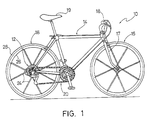
- Figure 1 is a side elevational view of a bicycle having a rear wheel with a bicycle hub assembly in accordance with the present invention;
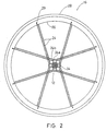
- Figure 2 is a side elevational view of the rear bicycle wheel with the bicycle hub assembly illustrated in Figure 1 in accordance with the present invention;
- Figure 3 is an edge elevational view of the rear bicycle wheel with the bicycle hub assembly illustrated in Figures 1 and 2 in accordance with the present invention;
- Figure 4 is a partial, enlarged elevational view of the bicycle hub assembly in accordance with the present invention, with a portion of the hub body broken away for purposes of illustration;
- Figure 5 is a rear elevational view of the bicycle hub assembly in accordance with the present invention;
- Figure 6 is a partial exploded perspective view of the bicycle hub assembly in accordance with the present invention;
- Figure 7 is a rear elevational view of the bicycle hub unit in accordance with the present invention;
- Figure 8 is a side elevational view of the sprocket assembly for the bicycle hub assembly in accordance with the present invention;
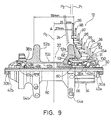
- Figure 9 is a rear elevational view of the bicycle hub assembly in accordance with the present invention, with the upper portion illustrated in cross section;
- Figure 10 a partial, enlarged cross sectional view of the bicycle hub assembly in accordance with the present invention; and
- Figure 11 a partial, enlarged cross sectional view of a modified version of a bicycle hub assembly in accordance with the present invention.
-
- Referring initially to Figure 1, a
bicycle 10 is illustrated with abicycle hub assembly 12 in accordance with the present invention. Thebicycle 10 basically has aframe 14 with front andrear wheels front fork 17 is coupled between theframe 14 and thefront wheel 15 in a conventional manner. Thefront wheel 15 is turned by turning ahandlebar 18, which is fixedly coupled to thefront fork 17. Therear wheel 16 is rotatably coupled to a rear portion of theframe 14. Theframe 14 also has a seat 19 adjustably coupled to frame 14 and adrive train 20 for propellingbicycle 10. - Since the parts of the
bicycle 10 are well known in the art, the parts of thebicycle 10 will not be discussed or illustrated in detail herein, except as they are modified in accordance with the present invention. Moreover, various conventional bicycle parts such as brakes, derailleurs, additional sprockets, etc., which are not illustrated and/or discussed in detail herein, can be used in conjunction with the present invention. - Turning now to Figures 2-4, the
rear wheel 16 basically includes the rearbicycle hub assembly 12 of the present invention, a plurality of outwardly extendingspokes 24 and anannular rim 26 with apneumatic tire 28 coupled thereto in a conventional manner. In the illustrated embodiment, therear wheel 16 has sixteenspokes 24 extending radially between thehub assembly 12 and theannular rim portion 26. Of course, it will be apparent to those skilled in the art from this disclosure that therear wheel 16 can have fewer ormore spokes 24 than illustrated if needed and/or desired. - The
rim 26 is constructed of a substantially rigid material, such as those materials, which are well known in the art. For example, therim 26 can be constructed of any suitable metallic material, such as plated steel, stainless steel, aluminum, magnesium or titanium, as well as other non-metallic materials, such as a carbon fiber composite, which can be utilized for a bicycle wheel. Therim 26 is relatively conventional. Therefore, rim 26 will not be discussed or illustrated in detail herein. - Each of the
spokes 24 has an outer end or spoke head coupled torim 26 by reinforcement members orwashers 29 and an inner threaded end coupled to the rearbicycle hub assembly 12 byspoke nipples washers 29 are designed to disperse the stresses applied torim 26 byspokes 24. Preferably, the inner ends ofspokes 24 are adjustable coupled to the rearbicycle hub assembly 12. More specifically, the inner ends ofspokes 24 are threadedly coupled to the rearbicycle hub assembly 12 byspoke nipples - Referring now to Figures 5-10, the
bicycle hub assembly 12 basically includes ahub axle 30, ahub unit 32, afreewheel 34 and asprocket assembly 36. Thehub axle 30 rotatably supports thehub unit 32, thefreewheel 34 and thesprocket assembly 36 about a center axis of rotation A by a pair of bearingassemblies hub axle 30 has a firstframe mounting end 30a and a secondframe mounting end 30b with the center axis A extending therebetween. - As seen in Figures 5 and 6, the
hub axle 30 is also preferably hollow with aquick release mechanism 40 extending therethrough for coupling therear wheel 16 to theframe 14 in a conventional manner. Thequick release mechanism 40 has a quick-release hub rod 41 extending through the axial center of thehub axle 30 with an adjustingnut 41a coupled to one end and a quick-release lever 41b coupled to other end. - As seen in Figure 9, the first and second frame mounting ends 30a and 30b of
hub axle 30 are threaded to receive a pair of nuts 42a and 42b.Nuts bearing assemblies hub body 50 and thehub axle 30 together when thehub unit 32 is assembled. As mentioned above, the first andsecond bearing assemblies hub body 50 onhub axle 30. As seen in Figures 9 and 10, the bearingassembly 38a basically includes a plurality ofballs 43a located between an inner race member 44a and anouter race member 45a. Similarly, the bearingassembly 38b basically includes a plurality ofballs 46b located between aninner race member 47b and anouter race member 48b. Since bearingassemblies - The
hub unit 32 basically includes ahub body 50 with a firstspoke mounting portion 52a located adjacent a first end of thehub body 50, a secondspoke mounting portion 52b located adjacent a second end of thehub body 50 and a centertubular portion 52c extending between the first and second ends of thehub body 50. An interior passageway 52d extends through thehub body 50 between the first and second ends of thehub body 50. Thebearing assemblies hub axle 30 within the interior passageway 52d. The remaining parts ofhub unit 32 are relatively conventional, and thus, the remaining parts ofhub unit 32 will not be discussed or illustrated in detail herein. - Preferably, the
hub body 50 is formed as a one-piece, unitary member. It will be apparent to those skilled in the art that thehub body 50 can be constructed of any substantially rigid material, such as those materials, which are known in the art. For example, thehub body 50 can be constructed of any suitable metallic material, such as plated steel, stainless steel, aluminum, magnesium or titanium, as well as other non-metallic materials, such as carbon fiber composite, ceramic or plastic. Moreover, the first mountingportion 52a and the second mountingportion 52b could be constructed of different materials from the centertubular portion 52c of thehub body 50 as need and/or desired. - The first spoke mounting
portion 52a extends radially outwardly from the first end of thehub body 50, while second spoke mountingportion 52b extends radially outwardly from the second end of thehub body 50. Thesecond mounting portion 52b is different from the first mountingportion 52a in that thefreewheel 34 is coupled to the first mountingportion 52a. Each spoke mountingportion spokes 24 thereto. - Preferably, the first spoke mounting
portion 52a has eight spoke openings with fourinner spoke openings 55a and fourouter spoke openings 56a.Spoke openings portion 52a includes fourattachment members 54a extending radially outwardly from thehub body 50 with two of the first spokeopenings attachment members 54a. Similarly, the second spoke mountingportion 52b has eight spoke openings with four inner spokeopenings 55b and four outer spokeopenings 56b. Spokeopenings portion 52b includes fourattachment members 54b extending radially outwardly from thehub body 50 with two of the second spokeopenings attachment members 54b. - As shown in Figures 2, 4 and 6, the
spoke attachment members spoke attachment members spoke attachment members 54a on the right side and thespoke attachment members 54b on the left side are aligned when view along the center axis A of thehub axle 30. - The number and shape of the
spoke attachment members - The first and second inner spoke
openings openings spoke openings rear wheel 16. In other words, thespokes 24 arranged in thespoke openings spokes 24 extend from thespoke attachment members rim 26. - As seen in Figure 4, each of the first and second spoke
openings spoke nipples spokes 24 therein. Each of the first and second spokeopenings larger diameter portion 58 and asmaller diameter portion 59. Thespokes 24 exit out of thesmaller diameter portions 59 of the first and second spokeopenings openings smaller diameter portion 59 where thespoke 24 exits out of the spoke opening. - The inner spoke
openings openings attachment members hub body 50 at different positions in the radial direction from the center of thehub axle 30, that is, at different positions in the radial direction in the plane that includes thehub axle 30. Thespoke openings nipples spokes 24. - Referring to Figures 9 and 10, the
freewheel 34 is operatively coupled between the first end of thehub axle 30 and the first end of thehub body 50. Thefreewheel 34 is relatively conventional, and thus, will not be discussed or illustrated in detail herein. The main difference between thefreewheel 34 of the present invention and other freewheels is thatfreewheel 34 is partially recessed into the first spoke mountingportion 52a. In particular, the first spoke mountingportion 52a has arecess 53 that is concentric with the interior passageway 52d for receiving an inner portion of thefreewheel 34 and an inner portion of thesprocket assembly 36 therein as discussed below. In other words, the first spoke mountingportion 52a overlaps the inner portion of thefreewheel 34 so that the axial spacing between the first and second spoke mountingportions bicycle hub assembly 12. - Referring to Figure 9, the
freewheel 34 is coupled tohub body 50 in a conventional manner and has a plurality of splines for receiving thesprocket assembly 36 thereon. Thefreewheel 34 includes of a drivingcylinder 60, a drivencylinder 62 having an outer peripheral surface withsplines 62a for nonrotatably coupling thesprocket assembly 36 thereto, a unidirectional rotation transmission mechanism (one-way clutch) 66 and two sets ofball bearings cylinder 62 to the drivingcylinder 60. The drivencylinder 62 is adapted, by means of the unidirectionalrotation transmission mechanism 66 and theball bearings cylinder 60. Theball bearings 70 that supports one end side of the drivencylinder 62 are supported by theouter race 45a of bearing assembly38a screwed onto the right-hand end of the drivingcylinder 60. One end side of the drivencylinder 62 of thefreewheel 34 is rotatably supported on thehub shaft 30 throughballs 43a and an inner race member 44a screwed onto thehub shaft 30. The unidirectionalrotation transmission mechanism 66 is so constructed that the drivencylinder 62 is provided withserrated teeth 80 on the inner periphery thereof between theball bearings cylinder 60 is provided on the outer periphery thereof withtransmission pawls 82 as seen in Figure 10. The transmission pawls 82 comes into mesh with theserrated teeth 80 upon the positive rotation of the drivencylinder 62 to transmit the driving power thereof to thehub body 50 that is splined engaged with the drivingcylinder 60 via thetubular support 84 of thehub body 50. - As best seen in Figure 10, the driven
cylinder 62 of thefreewheel 34 has an outwardly facingabutment surface 62b located at its inner axial end. Theabutment surface 62b limits inward movement of thesprocket assembly 36 alongsplines 62a of the drivencylinder 62. Thisabutment surface 62b is an annular surface that is located in a plane extending substantially perpendicular to the center axis A. The plane of theabutment surface 62b is located within therecess 53 of the first spoke mountingportion 52a of thehub body 50. In other words, the plane of theabutment surface 62b is located axial inward from the most outwardly facingedge 53a of the first spoke mountingportion 52a of thehub body 50. - Referring to Figure 10, the
sprocket assembly 36 is fixedly coupled to thefreewheel 34 for rotation therewith. Thesprocket assembly 36 basically includes a pair of washers orspacers 89, asupport member 90 with a plurality of sprockets 91-99 in the form of ring plates that are mounted on thesupport member 90. Thesupport member 90 and the sprockets 91-99 are fixedly retained on thefreewheel 34 by anend nut 100. The drive power transmitted to thesprocket assembly 36 is transmitted by thefreewheel 34 via a chain to thehub body 50 in only one direction as discussed above. - In the illustrated embodiment of Figure 10, one of the
washers 89 of thesprocket assembly 36 abut against theabutment surface 62b of thefreewheel 34. Of course, thewashers 89 of thesprocket assembly 36 can be remove completely, as seen in Figure 11, or replaced with a smaller washer to move thesprocket assembly 36 axially inward. - The
support member 90 axially spaces the sprockets 91-99 along thefreewheel 34. In the preferred embodiment, thesprocket assembly 36 has nine sprockets. Thesprocket assembly 36 is mounted on thefreewheel 34 such that the first spoke mountingportion 52a of thehub body 50 is at least partially located in a radial center portion of the innermost orlargest sprocket 99. Moreover, the innermost orlargest sprocket 99 has an inwardly facing side surface lying in a plane P1 that is substantially perpendicular to the center axis A. This plane P1 of the side surface of thesprocket 99 is located axially within 3.0 mm of a "center" of one of the first spokeopenings spoke openings smaller diameter portion 59 where thespoke 24 exit out of thespoke opening spoke openings sprocket 99 is located axially within 3.0 mm of plane P2 of the centers of thespoke openings sprocket 99 is located axially within 2.0 mm of the plane P2 of the centers of the first spokeopenings hub axle 32 on an axial side of the centers of the first spokeopenings hub body 50 as seen in Figure 10. When the plane P1 is located relative to thehub axle 32 on an axial side of the centers of the first spokeopenings hub body 50, the plane P1 of the side surface of thesprocket 99 is located axially within 3.0 mm of the plane P2 of the centers of the first spokeopenings - The
support member 90 basically includes abase portion 90a and a plurality ofsupport arms 90b extending radially outwardly from thebase portion 90a the sprockets 94-99 coupled thereto. Thebase portion 90a has an inner portion that is located withinrecess 53 of the first spoke mountingportion 52a. Also, the inner edge of thebase portion 90a is preferably substantially aligned with plane P1 of the side surface of thesprocket 99. Thesupport arms 90b are inclined toward the first spoke mountingportion 52a with respect to the center axis A so that the first spoke mountingportion 52a is at least partially located in a radial center portion of thesupport arms 90b and theinnermost sprocket 99. Thesupport arms 90b have a plurality of steps including vertical surfaces 90d that are substantially perpendicular to the center axis A and horizontal surfaces 90e that are substantially parallel to the center axis A. - In the illustrated embodiment, sprockets 91-93 are supported directly on the driven
cylinder 62, while the sprockets 94-99 are coupled by rivets orfasteners 102 to thesupport arms 90b of thesupport member 90, which is supported on the drivencylinder 62. Thebase portion 90a has a splined center bore 90c that mates with thesplines 62a of the drivencylinder 62 so that they rotate together. - The terms of degree such as "substantially", "about" and "approximately" as used herein mean a reasonable amount of deviation of the modified term such that the end result is not significantly changed. These terms should be construed as including a deviation of at least ± 5% of the modified term if this deviation would not negate the meaning of the word it modifies.
- While only selected embodiments have been chosen to illustrate the present invention, it will be apparent to those skilled in the art from this disclosure that various changes and modifications can be made herein without departing from the scope of the invention as defined in the appended claims. Furthermore, the foregoing description of the embodiments according to the present invention are provided for illustration only, and not for the purpose of limiting the invention as defined by the appended claims and their equivalents.
Claims (28)
- A bicycle hub assembly (12) comprising:a hub axle (30) having a center axis (A) extending between a first frame mounting end (30a) and a second frame mounting end (30b);a hub unit (32) having a hub body (50), a first spoke mounting portion (52a) located adjacent a first end of said hub body (50), a second spoke mounting portion (52b) located adjacent a second end of said hub body (50) and an interior passageway (52d) extending through said hub body (50) with said hub axle (30) being rotatably supported therein;a freewheel (34) operatively coupled between said first end of said hub axle (30) andsaid first end of said hub body (50); anda sprocket assembly (36) coupled to said freewheel (34) with a plurality of sprockets (91-99) axially spaced apart along said freewheel (34), said sprocket assembly (36) having an inner portion recessed within a recess (53) of said first spoke mounting portion (52a).
- A bicycle hub assembly (12) according to claim 1, wherein
said sprocket assembly (36) includes a base portion (90a) and a plurality of support arms (90b) extending radially outwardly from said base portion (90a) with some of said sprockets (94-99) coupled thereto, said support arms (90b) being inclined toward said first spoke mounting portion (52a) with respect to said center axis (A) so that said first spoke mounting portion (52a) is at least partially located in a radial center portion of said support arms (90b). - A bicycle hub assembly (12) according to claim 2, wherein
said support arms (90b) has a plurality of steps including vertical surfaces (90d) substantially perpendicular to said center axis (A) and horizontal surfaces (90e) substantially parallel to said center axis (A). - A bicycle hub assembly (12) according to any of claims 1 to 3, wherein
said first spoke mounting portion (52a) extends radially outwardly from said hub body (50). - A bicycle hub assembly (12) according to claim 1, wherein
said first spoke mounting portion (52a) includes four attachment members (54a) extending radially outwardly from said hub body (50) with two first spoke openings (55a, 56a) formed in each of said attachment members (54a) of said first spoke mounting portion (52a), and
said second spoke mounting portion (52b) includes four attachment members (54b) extending radially outwardly from said hub body (50) with two second spoke openings (55b, 56b) formed in each of said attachment members (54b) of said second spoke mounting portion (52b). - A bicycle hub assembly (12) according to any of claims 1 to 5, wherein.
said first spoke mounting portion (52a) includes a plurality of first spoke openings (55a, 56a) with longitudinal axes (B, C) that are tangentially arranged about an imaginary circle centered on said center axis (A), and
said second spoke mounting portion (52b) includes a plurality of second spoke openings (55b, 56b) with longitudinal axes (B, C) that are tangentially arranged about an imaginary circle centered on said center axis (A). - A bicycle hub assembly (12) according to any of claims 1 to 6, wherein
a portion of said freewheel (34) is axially positioned in said recess (53) of said first spoke mounting portion (52a) that is concentric with said interior passageway (52d). - A bicycle hub assembly (12) according to any of claims 1 to 7, wherein
said first spoke mounting portion (52a) includes a plurality of first spoke openings (55a, 56a) with a through hole with a larger diameter portion (58) and a smaller diameter portion (59), and
said second spoke mounting portion (52b) includes a plurality of second spoke openings (55b, 56b) with a through hole with a larger diameter portion (58) and a smaller diameter portion (59). - A bicycle hub assembly (12) comprising:a hub axle (30) having a center axis (A) extending between a first frame mounting end (30a) and a second frame mounting end (30b);a hub body (50) having a first end of said hub body (50) with a most outwardly facing edge and a second end of said hub body (50), said hub axle (30) rotatably supporting said hub body (50);a freewheel (34) operatively coupled between said first end of said hub axle (30) andsaid first end of said hub body (50), said freewheel (34) having an outwardly facing abutment surface (62b) being located axially inward of said most outwardly facing edge of said hub body (50).
- A bicycle hub assembly (12) according to claim 11, further comprising
a sprocket assembly (36) including a plurality of sprockets (91-99) axially spaced apart along said freewheel (34) with a portion of said first end of said hub body (50) being at least partially located in a radial center portion of one of said sprockets (91-99). - A bicycle hub assembly (12) according to claim 9 or 10, wherein
a sprocket assembly (36) including a base portion (90a) and a plurality of support arms (90b) extending radially outwardly from said base portion (90a) with a plurality of sprockets (94-99) coupled thereto, said support arms (90b) being inclined toward said first end of said hub body (50) with respect to said center axis (A) so that said first end of said hub body (50) is at least partially located in a radial center portion of said support arms (90b). - A bicycle hub assembly (12) according to claim 11, wherein
said support arms (90b) has a plurality of steps including vertical surfaces (90d) substantially perpendicular to said center axis (A) and horizontal surfaces (90e) substantially parallel to said center axis (A). - A bicycle hub assembly (12) according to any of claims 9 to 11, wherein
said first end of said hub body (50) has a first spoke mounting portion (52a) extending radially outwardly from said hub body (50). - A bicycle hub assembly (12) according to any of claims 9 to 13, wherein.
said first end of said hub body (50) has a first spoke mounting portion (52a) with four attachment members (54a) extending radially outwardly from said hub body (50) with two first spoke openings (55a, 56a) formed in each of said attachment members (54a) of said first spoke mounting portion (52a). - A bicycle hub assembly (12) according to any of claims 9 to 14, wherein
said first end of said hub body (50) has a first spoke mounting portion (52a) with a plurality of first spoke openings (55a, 56a) with longitudinal axes (B, C) that are tangentially arranged about an imaginary circle centered on said center axis (A). - A bicycle hub assembly (12) according to claim 15, wherein
said first spoke openings (55a, 56a) have a through hole with a larger diameter portion (58) and a smaller diameter portion (59). - A bicycle hub assembly (12) according to claim 15, wherein
said first end of said hub body (50) has a first spoke mounting portion (52a) including a plurality of first spoke openings (55a, 56a) with longitudinal axes (B, C) that are tangentially arranged about an imaginary circle centered on said center axis (A), and
said second end of said hub body (50) has a second spoke mounting portion (52b) including a plurality of second spoke openings (55b, 56b) with longitudinal axes (B, C) that are tangentially arranged about an imaginary circle centered on said center axis (A). - A bicycle hub assembly (12) comprising:a hub axle (30) having a center axis (A) extending between a first frame mounting end (30a) and a second frame mounting end (30b);a hub unit (32) having a hub body (50) with said hub axle (30) being rotatably supported therein, a first spoke mounting portion (52a) with a plurality of first spoke openings (55a, 56a) located adjacent a first end of said hub body (50), and a second spoke mounting portion (52b) located adjacent a second end of said hub body (50);a freewheel (34) operatively coupled between said first end of said hub axle (30) andsaid first end of said hub body (50); anda sprocket assembly (36) coupled to said freewheel (34) with a plurality of sprockets (91-99) axially spaced apart along said freewheel (34), said sprockets (91-99) having a largest sprocket (99) with an inwardly facing side surface lying in a plane substantially perpendicular to said center axis (A), said plane of said side surface of said largest sprocket (99) being located axially within 3.0 mm of a center of one of said first spoke openings (55a, 56a), said sprocket assembly (36) having an inner portion recessed within a recess (53) of said first spoke mounting portion (52a).
- A bicycle hub assembly (12) according to claim 18, wherein
said plane of said side surface of said largest sprocket (99) is located relative to said hub axle (30) on an axial side of said center of said one of said first spoke openings (55a, 56a) that is closest to said second end of said hub body (50). - A bicycle hub assembly (12) according to claim 18 or 19, wherein
said plane of said side surface of said largest sprocket (99) is located relative to said hub axle (30) on an axial side of said center of said one of said first spoke openings (55a, 56a) that is closest to said first end of said hub body (50). - A bicycle hub assembly (12) according to any of claims 18 to 20, wherein
said plane of said side surface of said largest sprocket (99) is located axially within 2.0 mm of said center of said one of said first spoke openings (55a, 56a). - A bicycle hub assembly (12) according to claim 18 to 21, wherein
said sprocket assembly (36) includes a base portion (90a) and a plurality of support arms (90b) extending radially outwardly from said base portion (90a) with some of said sprockets (91-93) coupled thereto, said support arms (90b) being inclined toward said first spoke mounting portion (52a) with respect to said center axis (A) so that said first spoke mounting portion (52a) is at least partially located in a radial center portion of said support arms (90b). - A bicycle hub assembly (12) according to claim 22, wherein
said support arms (90b) has a plurality of steps including vertical surfaces (90d) substantially perpendicular to said center axis (A) and horizontal surfaces (90e) substantially parallel to said center axis (A). - A bicycle hub assembly (12) according to any of claims 18 to 23, wherein
said first spoke mounting portion (52a) extends radially outwardly from said hub body (50). - A bicycle hub assembly (12) according to any of claims 18 to 24, wherein
said first spoke mounting portion (52a) includes four attachment members (54a) extending radially outwardly from said hub body (50) with two of said first spoke openings (55a, 56a) formed in each of said attachment members (54a) of said first spoke mounting portion (52a). - A bicycle hub assembly (12) according to any of claims 18 to 25, wherein.
said first spoke openings (55a, 56a) have longitudinal axes (B, C) that are tangentially arranged about an imaginary circle centered on said center axis (A). - A bicycle hub assembly (12) according to any of claims 18 to 26, wherein
a portion of said freewheel (34) is axially positioned in said recess (53) of said first spoke mounting portion (52a) that is concentric with said interior passageway (52d). - A bicycle hub assembly (12) according to any of claims 18 to 27, wherein
said first spoke mounting portion (52a) includes a plurality of first spoke openings (55a, 56a) with a through hole with a larger diameter portion (58) and a smaller diameter portion (59).
Applications Claiming Priority (2)
| Application Number | Priority Date | Filing Date | Title |
|---|---|---|---|
| US09/656,376 US6382381B1 (en) | 2000-09-06 | 2000-09-06 | Bicycle hub assembly |
| US656376 | 2000-09-06 |
Publications (2)
| Publication Number | Publication Date |
|---|---|
| EP1186446A2 true EP1186446A2 (en) | 2002-03-13 |
| EP1186446A3 EP1186446A3 (en) | 2005-03-30 |
Family
ID=24632757
Family Applications (1)
| Application Number | Title | Priority Date | Filing Date |
|---|---|---|---|
| EP01121256A Withdrawn EP1186446A3 (en) | 2000-09-06 | 2001-09-05 | Bicycle hub assembly |
Country Status (6)
| Country | Link |
|---|---|
| US (1) | US6382381B1 (en) |
| EP (1) | EP1186446A3 (en) |
| JP (1) | JP3545373B2 (en) |
| CN (3) | CN1495051A (en) |
| CZ (1) | CZ20013119A3 (en) |
| TW (1) | TW576808B (en) |
Cited By (8)
| Publication number | Priority date | Publication date | Assignee | Title |
|---|---|---|---|---|
| EP1431172A3 (en) * | 2002-12-21 | 2005-05-04 | SRAM Deutschland GmbH | Multiple sprocket assembly |
| DE102006034394A1 (en) * | 2005-10-20 | 2007-05-10 | Shimano Inc., Sakai City | Component of a bicycle wheel |
| EP1964769A3 (en) * | 2007-02-07 | 2008-09-17 | Shimano Inc. | Bicycle rear sprocket assembly and sprocket |
| DE102010033454A1 (en) | 2010-08-05 | 2012-02-09 | Frank Bäseke | Wheel hub, particularly for bicycle, has hub body rotatably mounted on hub axle, where hub body has two spoke wheels projecting in radial direction |
| CN102624141A (en) * | 2011-01-28 | 2012-08-01 | 深圳飞能能源有限公司 | High-speed flywheel battery rotor |
| US9063024B2 (en) | 2011-08-29 | 2015-06-23 | Shimano Inc. | Bicycle rear hub |
| TWI504522B (en) * | 2011-08-29 | 2015-10-21 | Shimano Kk | Bicycle rear hub |
| EP2452865B1 (en) | 2010-11-12 | 2016-08-10 | Shimano Inc. | Sprocket support structure |
Families Citing this family (69)
| Publication number | Priority date | Publication date | Assignee | Title |
|---|---|---|---|---|
| EP1407962A1 (en) * | 2002-10-11 | 2004-04-14 | Campagnolo Srl | Sprocket support member for a bicycle sprocket assembly |
| US6866604B2 (en) * | 2003-01-17 | 2005-03-15 | Shimano, Inc. | Multiple level sprocket support for a bicycle |
| JP4145808B2 (en) * | 2004-01-16 | 2008-09-03 | 株式会社シマノ | Internal gear shifting hub for bicycles |
| JP2005231556A (en) * | 2004-02-20 | 2005-09-02 | Shimano Inc | Hub for bicycle |
| US20060145530A1 (en) * | 2004-05-28 | 2006-07-06 | Rinard Damon | Flangeless and straight spoked bicycle wheel set |
| DE102004027963B4 (en) * | 2004-06-08 | 2015-12-24 | Sram Deutschland Gmbh | Riveted sprocket set |
| US7585240B2 (en) * | 2005-02-03 | 2009-09-08 | Shimano Inc. | Bicycle sprocket assembly |
| DE602005015425D1 (en) * | 2005-05-02 | 2009-08-27 | Campagnolo Srl | Wheel hub for a bicycle spoked wheel |
| US7435197B2 (en) * | 2005-05-11 | 2008-10-14 | Shimano Inc. | Rear sprocket for bicycle transmission |
| USD555050S1 (en) * | 2005-12-16 | 2007-11-13 | Shimano Inc. | Front derailleur for a bicycle |
| US20080004143A1 (en) * | 2006-06-16 | 2008-01-03 | Shimano Inc. | Bicycle sprocket assembly |
| US7717212B2 (en) * | 2006-08-25 | 2010-05-18 | Split Pivot, Inc. | Vehicle suspension systems for seperated acceleration responses |
| US7854673B2 (en) * | 2006-08-31 | 2010-12-21 | Shimano Inc. | Bicycle sprocket assembly having a reinforcement member coupled between sprockets |
| ITMI20071661A1 (en) * | 2007-08-09 | 2009-02-10 | Campagnolo Srl | ASSEEME OF WHEELS TOOTHED FOR A BICYCLE |
| ITMI20071658A1 (en) | 2007-08-09 | 2009-02-10 | Campagnolo Srl | PINION MODULE FOR A BICYCLE AND SPROCKET PACK INCLUDING THIS MODULE |
| ITMI20071660A1 (en) * | 2007-08-09 | 2009-02-10 | Campagnolo Srl | MOTION BIKE TRANSMISSION SYSTEM |
| ITMI20071659A1 (en) * | 2007-08-09 | 2009-02-10 | Campagnolo Srl | SPROCKET ASSEMBLY FOR A REAR BICYCLE WHEEL AND SPROCKET PACK INCLUDING SUCH ASSEMBLY |
| US7871347B2 (en) * | 2007-10-11 | 2011-01-18 | Shimano Inc. | Bicycle rear sprocket assembly |
| DE102008010903A1 (en) * | 2008-02-23 | 2009-08-27 | Sram Deutschland Gmbh | Weight-optimized multi-sprocket wheel for a bicycle |
| US20100099530A1 (en) * | 2008-03-28 | 2010-04-22 | Douglas Chiang | Bicycle Cogset |
| US20090243250A1 (en) * | 2008-03-28 | 2009-10-01 | Tien Hsin Industries Co., Ltd. | Bicycle sprocket assembly |
| US20100009794A1 (en) * | 2008-07-10 | 2010-01-14 | Douglas Chiang | Sprocket assembly |
| US9193416B2 (en) * | 2009-11-30 | 2015-11-24 | Shimano Inc. | Bicycle sprocket support assembly |
| US8747271B2 (en) * | 2011-03-12 | 2014-06-10 | General Electric Company | Wheel rim assembly and method |
| TWI585000B (en) * | 2011-07-13 | 2017-06-01 | Sram De Gmbh | A multi-sprocket equipped with a small sprocket is used for the transmission of the bicycle transmission |
| DE102012020563A1 (en) * | 2012-10-12 | 2014-04-17 | Sram Deutschland Gmbh | fastening device |
| US9421818B2 (en) | 2012-12-21 | 2016-08-23 | Shimano Inc. | Bicycle hub and bicycle wheel |
| US9533735B2 (en) * | 2013-07-19 | 2017-01-03 | Sram Deutschland Gmbh | Multiple-sprocket arrangement for a bicycle gearing |
| US20160214433A1 (en) * | 2015-01-23 | 2016-07-28 | Specialized Bicycle Components, Inc. | Bicycle wheel and hub |
| US20160272002A1 (en) | 2015-03-17 | 2016-09-22 | Praxis Works LLC | Cassette and bicycle wheel assembly |
| US9511819B1 (en) * | 2015-05-25 | 2016-12-06 | Shimano Inc. | Bicycle rear sprocket assembly |
| US10562588B2 (en) | 2015-09-01 | 2020-02-18 | The Hive Global, Inc | Bicycle cassette with locking connection |
| CN107531311B (en) * | 2015-12-17 | 2019-11-15 | 深圳一哥智行科技有限公司 | Electric bicycle hub |
| CN107097587A (en) * | 2016-02-23 | 2017-08-29 | 上海赤焰实业有限公司 | A kind of improved bicycle drive shaft |
| WO2017165226A1 (en) * | 2016-03-24 | 2017-09-28 | The Hive Global, Inc. | Bicycle crank with spindle attachment structure |
| US9994285B2 (en) | 2016-06-15 | 2018-06-12 | Shimano Inc. | Multiple bicycle sprocket assembly |
| US10093388B2 (en) * | 2016-06-28 | 2018-10-09 | Shimano Inc. | Bicycle rear sprocket assembly |
| US10053187B2 (en) * | 2016-07-07 | 2018-08-21 | Shimano Inc. | Bicycle rear sprocket assembly and bicycle rear sprocket |
| US10112681B2 (en) * | 2016-07-21 | 2018-10-30 | Shimano Inc. | Bicycle sprocket supporting member and bicycle sprocket assembly |
| US9868491B1 (en) * | 2016-07-21 | 2018-01-16 | Shimano Inc. | Bicycle sprocket assembly |
| US10377445B2 (en) * | 2016-09-20 | 2019-08-13 | Shimano Inc. | Bicycle front sprocket assembly |
| US20180257742A1 (en) * | 2017-03-13 | 2018-09-13 | Drivetrain Tech Solution Inc. | Sprocket assembly of bicycle |
| US10442496B2 (en) * | 2017-03-29 | 2019-10-15 | Shimano Inc. | Bicycle sprocket assembly |
| CN111469972B (en) * | 2017-05-30 | 2023-02-17 | 株式会社岛野 | Bicycle rear sprocket assembly |
| US10377174B2 (en) | 2017-08-09 | 2019-08-13 | Shimano Inc. | Bicycle hub assembly |
| US10946931B2 (en) * | 2017-09-22 | 2021-03-16 | Shimano Inc. | Bicycle rear sprocket assembly and bicycle drive train |
| TWI791156B (en) * | 2017-05-30 | 2023-02-01 | 日商島野股份有限公司 | Bicycle hub assembly |
| US11332213B2 (en) | 2017-05-30 | 2022-05-17 | Shimano Inc. | Bicycle rear sprocket assembly and bicycle drive train |
| US11220309B2 (en) | 2017-05-30 | 2022-01-11 | Shimano Inc. | Bicycle rear sprocket assembly |
| US10752320B2 (en) | 2017-09-22 | 2020-08-25 | Shimano Inc. | Bicycle rear hub assembly |
| TWI697417B (en) * | 2017-05-30 | 2020-07-01 | 日商島野股份有限公司 | Bicycle hub assembly |
| US11179967B2 (en) | 2017-05-30 | 2021-11-23 | Shimano Inc. | Bicycle hub assembly |
| CN108973524B (en) * | 2017-05-30 | 2022-01-04 | 株式会社岛野 | Bicycle rear hub assembly |
| US11059541B2 (en) | 2017-05-30 | 2021-07-13 | Shimano Inc. | Bicycle hub assembly |
| US11351815B2 (en) | 2017-08-21 | 2022-06-07 | The Hive Global, Inc. | Bicycle cassette with clamping connection |
| US10525768B2 (en) * | 2017-10-31 | 2020-01-07 | Shimano Inc. | Bicycle hub assembly |
| US10766301B2 (en) * | 2017-12-14 | 2020-09-08 | Shimano Inc. | Rear wheel fixing mechanism for a bicycle |
| DE102019206778B4 (en) * | 2018-05-24 | 2026-05-28 | Shimano Inc. | Bicycle chainring and bicycle drivetrain |
| US11932351B2 (en) | 2020-07-17 | 2024-03-19 | The Hive Global, Inc. | Conical bicycle cassette sprocket structure |
| EP3960606A1 (en) * | 2020-09-01 | 2022-03-02 | SRAM Deutschland GmbH | Multi-sprocket assembly and rear wheel assembly for bicycle with derailleur |
| DE102020005373A1 (en) * | 2020-09-01 | 2022-03-03 | Sram Deutschland Gmbh | Multiple sprocket assembly for a rear wheel assembly for a bicycle and rear wheel assembly |
| US11529827B2 (en) * | 2020-12-10 | 2022-12-20 | Tien Hsin Industries Co., Ltd. | Transmission assembly of a bicycle |
| US12233975B2 (en) | 2021-03-26 | 2025-02-25 | The Hive Global Inc. | Telescopic bicycle seatpost with adjustable height and fixed frame insertion |
| US12030586B2 (en) | 2021-07-12 | 2024-07-09 | The Hive Global, Inc. | Seal for bicycle crank with differential chainring motion |
| US12187384B2 (en) * | 2022-08-30 | 2025-01-07 | Shimano Inc. | Rear sprocket |
| CN218408333U (en) * | 2022-11-02 | 2023-01-31 | 深圳市壹马赫科技有限公司 | Novel bicycle flywheel |
| CN120435394A (en) | 2022-11-14 | 2025-08-05 | 劲锋铁马股份有限公司 | Hub system, method and apparatus with adjustable dead zone |
| US12252216B2 (en) * | 2023-06-27 | 2025-03-18 | Shimano Inc. | Rear sprocket assembly |
| TWI863613B (en) * | 2023-10-06 | 2024-11-21 | 日馳企業股份有限公司 | Transmission device for bicycle |
Family Cites Families (9)
| Publication number | Priority date | Publication date | Assignee | Title |
|---|---|---|---|---|
| JPS59102504U (en) | 1982-12-27 | 1984-07-10 | 株式会社シマノ | bicycle hub |
| DE3331557A1 (en) * | 1983-09-01 | 1985-03-21 | Fichtel & Sachs Ag, 8720 Schweinfurt | DRIVE HUB WITH AXLE FOR BICYCLES OR THE LIKE |
| JPH04297390A (en) | 1991-03-27 | 1992-10-21 | Shimano Inc | Multistage wheel for bicycle rear wheel |
| WO1993006380A1 (en) * | 1991-09-19 | 1993-04-01 | Hybo Science, Inc. | Bicycle hub incorporating hyperboloidal clutch |
| GB9203247D0 (en) * | 1992-02-15 | 1992-04-01 | James Kenneth W | Improvements in and relating to hub assemblies |
| US5460254A (en) * | 1994-02-09 | 1995-10-24 | Huang; Jung Y. | Freehub |
| DE19518676A1 (en) * | 1995-05-22 | 1996-11-28 | Fichtel & Sachs Ag | Bicycle freewheel hub with hub axis and sleeve |
| JP3069284B2 (en) | 1996-01-26 | 2000-07-24 | 株式会社シマノ | Bicycle hub |
| US5954604A (en) | 1996-11-21 | 1999-09-21 | Shimano, Inc. | Multiple sprocket assembly for a bicycle |
-
2000
- 2000-09-06 US US09/656,376 patent/US6382381B1/en not_active Expired - Fee Related
-
2001
- 2001-08-28 TW TW090121189A patent/TW576808B/en not_active IP Right Cessation
- 2001-08-29 CZ CZ20013119A patent/CZ20013119A3/en unknown
- 2001-09-05 CN CNA200310101486XA patent/CN1495051A/en active Pending
- 2001-09-05 CN CNA2003101014874A patent/CN1495050A/en active Pending
- 2001-09-05 EP EP01121256A patent/EP1186446A3/en not_active Withdrawn
- 2001-09-05 CN CNB011324465A patent/CN1171742C/en not_active Expired - Fee Related
- 2001-09-06 JP JP2001270378A patent/JP3545373B2/en not_active Expired - Fee Related
Non-Patent Citations (1)
| Title |
|---|
| None |
Cited By (15)
| Publication number | Priority date | Publication date | Assignee | Title |
|---|---|---|---|---|
| EP1431172A3 (en) * | 2002-12-21 | 2005-05-04 | SRAM Deutschland GmbH | Multiple sprocket assembly |
| US7344463B2 (en) | 2002-12-21 | 2008-03-18 | Sram Corporation | Sprocket assembly |
| DE102006034394A1 (en) * | 2005-10-20 | 2007-05-10 | Shimano Inc., Sakai City | Component of a bicycle wheel |
| US7374251B2 (en) | 2005-10-20 | 2008-05-20 | Shimano Inc. | Connection of Spokes to hub and rim in bicycle wheel |
| EP1964769A3 (en) * | 2007-02-07 | 2008-09-17 | Shimano Inc. | Bicycle rear sprocket assembly and sprocket |
| US7931553B2 (en) | 2007-02-07 | 2011-04-26 | Shimano, Inc. | Bicycle sprocket apparatus with a chain support structure |
| DE102010033454A1 (en) | 2010-08-05 | 2012-02-09 | Frank Bäseke | Wheel hub, particularly for bicycle, has hub body rotatably mounted on hub axle, where hub body has two spoke wheels projecting in radial direction |
| DE102010033454B4 (en) * | 2010-08-05 | 2013-10-31 | Frank Bäseke | wheel hub |
| EP2452865B1 (en) | 2010-11-12 | 2016-08-10 | Shimano Inc. | Sprocket support structure |
| EP2452865B2 (en) † | 2010-11-12 | 2025-07-16 | Shimano Inc. | Sprocket support structure |
| CN102624141A (en) * | 2011-01-28 | 2012-08-01 | 深圳飞能能源有限公司 | High-speed flywheel battery rotor |
| CN102624141B (en) * | 2011-01-28 | 2014-03-19 | 深圳飞能能源有限公司 | High-speed flywheel battery rotor |
| US9063024B2 (en) | 2011-08-29 | 2015-06-23 | Shimano Inc. | Bicycle rear hub |
| TWI504522B (en) * | 2011-08-29 | 2015-10-21 | Shimano Kk | Bicycle rear hub |
| TWI505953B (en) * | 2011-08-29 | 2015-11-01 | Shimano Kk | Bicycle rear hub |
Also Published As
| Publication number | Publication date |
|---|---|
| CN1495050A (en) | 2004-05-12 |
| TW576808B (en) | 2004-02-21 |
| CN1342562A (en) | 2002-04-03 |
| EP1186446A3 (en) | 2005-03-30 |
| JP3545373B2 (en) | 2004-07-21 |
| CN1495051A (en) | 2004-05-12 |
| US6382381B1 (en) | 2002-05-07 |
| CN1171742C (en) | 2004-10-20 |
| JP2002104262A (en) | 2002-04-10 |
| CZ20013119A3 (en) | 2002-08-14 |
Similar Documents
| Publication | Publication Date | Title |
|---|---|---|
| US6382381B1 (en) | Bicycle hub assembly | |
| US6488603B2 (en) | Freewheel for a bicycle | |
| US6523659B2 (en) | Bicycle hub with tight connection ratchet and detachable freewheel | |
| EP1495879B1 (en) | Bicycle hub outer and bicycle hub | |
| US6669306B1 (en) | Bicycle hub axle assembly | |
| USRE42986E1 (en) | Bicycle disc brake hub | |
| US6497314B2 (en) | Bicycle hub with sliding engagement member and detachable freewheel | |
| US6435622B1 (en) | Bicycle hub with threaded spacer and detachable freewheel | |
| US6886894B2 (en) | Bicycle hub axle | |
| US7585240B2 (en) | Bicycle sprocket assembly | |
| US7029075B2 (en) | Bicycle hub sealing assembly | |
| EP1721823B1 (en) | Rear sprocket for bicycle transmission | |
| US7191884B2 (en) | Bicycle hub | |
| US20020067068A1 (en) | Bicycle hub with spacer and detachable freewheel | |
| US20030000779A1 (en) | Bicycle disc brake hub | |
| US20060094550A1 (en) | Bicycle crankset |
Legal Events
| Date | Code | Title | Description |
|---|---|---|---|
| PUAI | Public reference made under article 153(3) epc to a published international application that has entered the european phase |
Free format text: ORIGINAL CODE: 0009012 |
|
| AK | Designated contracting states |
Kind code of ref document: A2 Designated state(s): AT BE CH CY DE DK ES FI FR GB GR IE IT LI LU MC NL PT SE TR |
|
| AX | Request for extension of the european patent |
Free format text: AL;LT;LV;MK;RO;SI |
|
| PUAL | Search report despatched |
Free format text: ORIGINAL CODE: 0009013 |
|
| AK | Designated contracting states |
Kind code of ref document: A3 Designated state(s): AT BE CH CY DE DK ES FI FR GB GR IE IT LI LU MC NL PT SE TR |
|
| AX | Request for extension of the european patent |
Extension state: AL LT LV MK RO SI |
|
| 17P | Request for examination filed |
Effective date: 20050314 |
|
| AKX | Designation fees paid |
Designated state(s): DE FR GB IE IT NL |
|
| RAP1 | Party data changed (applicant data changed or rights of an application transferred) |
Owner name: SHIMANO INC. |
|
| STAA | Information on the status of an ep patent application or granted ep patent |
Free format text: STATUS: THE APPLICATION IS DEEMED TO BE WITHDRAWN |
|
| 18D | Application deemed to be withdrawn |
Effective date: 20070403 |