EP1186369A1 - Electrode tip dressing apparatus - Google Patents
Electrode tip dressing apparatus Download PDFInfo
- Publication number
- EP1186369A1 EP1186369A1 EP01121180A EP01121180A EP1186369A1 EP 1186369 A1 EP1186369 A1 EP 1186369A1 EP 01121180 A EP01121180 A EP 01121180A EP 01121180 A EP01121180 A EP 01121180A EP 1186369 A1 EP1186369 A1 EP 1186369A1
- Authority
- EP
- European Patent Office
- Prior art keywords
- chip
- capturing case
- dressing
- tip
- chip capturing
- Prior art date
- Legal status (The legal status is an assumption and is not a legal conclusion. Google has not performed a legal analysis and makes no representation as to the accuracy of the status listed.)
- Granted
Links
- 238000003780 insertion Methods 0.000 claims description 18
- 230000037431 insertion Effects 0.000 claims description 18
- 230000033001 locomotion Effects 0.000 claims description 7
- 230000005489 elastic deformation Effects 0.000 claims description 2
- 238000005498 polishing Methods 0.000 abstract description 8
- 238000003466 welding Methods 0.000 description 33
- 238000013459 approach Methods 0.000 description 5
- 238000007664 blowing Methods 0.000 description 5
- 238000000071 blow moulding Methods 0.000 description 4
- 239000000463 material Substances 0.000 description 4
- 239000004677 Nylon Substances 0.000 description 3
- 238000013461 design Methods 0.000 description 3
- 238000001514 detection method Methods 0.000 description 3
- 229920001971 elastomer Polymers 0.000 description 3
- 229920001778 nylon Polymers 0.000 description 3
- 238000012805 post-processing Methods 0.000 description 3
- 238000012545 processing Methods 0.000 description 3
- 239000011347 resin Substances 0.000 description 3
- 229920005989 resin Polymers 0.000 description 3
- 239000000725 suspension Substances 0.000 description 3
- 230000002411 adverse Effects 0.000 description 2
- 230000000694 effects Effects 0.000 description 2
- 239000002184 metal Substances 0.000 description 2
- 229910052751 metal Inorganic materials 0.000 description 2
- 238000000034 method Methods 0.000 description 2
- 229920000139 polyethylene terephthalate Polymers 0.000 description 2
- 239000005020 polyethylene terephthalate Substances 0.000 description 2
- 230000008569 process Effects 0.000 description 2
- RYGMFSIKBFXOCR-UHFFFAOYSA-N Copper Chemical compound [Cu] RYGMFSIKBFXOCR-UHFFFAOYSA-N 0.000 description 1
- 229910000831 Steel Inorganic materials 0.000 description 1
- 238000005299 abrasion Methods 0.000 description 1
- 230000015572 biosynthetic process Effects 0.000 description 1
- 229910052802 copper Inorganic materials 0.000 description 1
- 239000010949 copper Substances 0.000 description 1
- 230000007613 environmental effect Effects 0.000 description 1
- 238000002347 injection Methods 0.000 description 1
- 239000007924 injection Substances 0.000 description 1
- 238000012423 maintenance Methods 0.000 description 1
- 230000007257 malfunction Effects 0.000 description 1
- 238000004519 manufacturing process Methods 0.000 description 1
- 230000007246 mechanism Effects 0.000 description 1
- 238000012986 modification Methods 0.000 description 1
- 230000004048 modification Effects 0.000 description 1
- -1 polyethylene terephthalate Polymers 0.000 description 1
- 238000003825 pressing Methods 0.000 description 1
- 230000009467 reduction Effects 0.000 description 1
- 229920002379 silicone rubber Polymers 0.000 description 1
- 239000010959 steel Substances 0.000 description 1
Images











Classifications
-
- B—PERFORMING OPERATIONS; TRANSPORTING
- B23—MACHINE TOOLS; METAL-WORKING NOT OTHERWISE PROVIDED FOR
- B23K—SOLDERING OR UNSOLDERING; WELDING; CLADDING OR PLATING BY SOLDERING OR WELDING; CUTTING BY APPLYING HEAT LOCALLY, e.g. FLAME CUTTING; WORKING BY LASER BEAM
- B23K11/00—Resistance welding; Severing by resistance heating
- B23K11/30—Features relating to electrodes
-
- B—PERFORMING OPERATIONS; TRANSPORTING
- B23—MACHINE TOOLS; METAL-WORKING NOT OTHERWISE PROVIDED FOR
- B23K—SOLDERING OR UNSOLDERING; WELDING; CLADDING OR PLATING BY SOLDERING OR WELDING; CUTTING BY APPLYING HEAT LOCALLY, e.g. FLAME CUTTING; WORKING BY LASER BEAM
- B23K11/00—Resistance welding; Severing by resistance heating
- B23K11/30—Features relating to electrodes
- B23K11/3063—Electrode maintenance, e.g. cleaning, grinding
-
- Y—GENERAL TAGGING OF NEW TECHNOLOGICAL DEVELOPMENTS; GENERAL TAGGING OF CROSS-SECTIONAL TECHNOLOGIES SPANNING OVER SEVERAL SECTIONS OF THE IPC; TECHNICAL SUBJECTS COVERED BY FORMER USPC CROSS-REFERENCE ART COLLECTIONS [XRACs] AND DIGESTS
- Y10—TECHNICAL SUBJECTS COVERED BY FORMER USPC
- Y10T—TECHNICAL SUBJECTS COVERED BY FORMER US CLASSIFICATION
- Y10T409/00—Gear cutting, milling, or planing
- Y10T409/30—Milling
- Y10T409/303752—Process
-
- Y—GENERAL TAGGING OF NEW TECHNOLOGICAL DEVELOPMENTS; GENERAL TAGGING OF CROSS-SECTIONAL TECHNOLOGIES SPANNING OVER SEVERAL SECTIONS OF THE IPC; TECHNICAL SUBJECTS COVERED BY FORMER USPC CROSS-REFERENCE ART COLLECTIONS [XRACs] AND DIGESTS
- Y10—TECHNICAL SUBJECTS COVERED BY FORMER USPC
- Y10T—TECHNICAL SUBJECTS COVERED BY FORMER US CLASSIFICATION
- Y10T409/00—Gear cutting, milling, or planing
- Y10T409/30—Milling
- Y10T409/304088—Milling with means to remove chip
-
- Y—GENERAL TAGGING OF NEW TECHNOLOGICAL DEVELOPMENTS; GENERAL TAGGING OF CROSS-SECTIONAL TECHNOLOGIES SPANNING OVER SEVERAL SECTIONS OF THE IPC; TECHNICAL SUBJECTS COVERED BY FORMER USPC CROSS-REFERENCE ART COLLECTIONS [XRACs] AND DIGESTS
- Y10—TECHNICAL SUBJECTS COVERED BY FORMER USPC
- Y10T—TECHNICAL SUBJECTS COVERED BY FORMER US CLASSIFICATION
- Y10T409/00—Gear cutting, milling, or planing
- Y10T409/30—Milling
- Y10T409/3042—Means to remove scale or raised surface imperfection
- Y10T409/304256—Means to remove flash or burr
Definitions
- the present invention relates to an electrode tip dressing apparatus of welding machines capable of effectively collecting chips generated when an electrode tip is dressed.
- an electrode tip used for spot welding is worn (subjected to deformation and abrasion) when a welding work is repeatedly carried out by using the electrode tip.
- a desired quality of the welding work cannot be obtained.
- the electrode tip is periodically cleaned by dressing to maintain the quality of the welding work.
- Japanese Patent Unexamined Publication No. 6-122082 discloses an art for dressing electrode tips in such a manner that the upper and lower surfaces of a dresser are clamped under a pressure between a pair of electrode tips oppositely disposed at both ends of a welding gun and then the electrode tips are dressed by polishing when the welding gun is swung about an axial center of the electrode tips.
- a collection vessel is disposed below the dresser so as to reuse the chips collected in the collection vessel.
- a copper is often as used as a material of the electrode tip for the spot welding.
- the electrode tip is ground more frequently to maintain a proper quality of the welding works, and an amount of ground or polished chips of the electrode tip is increased thereby.
- it is necessary to increase a chip collection rate (efficiency) and to effectively reuse the chips to reduce a material cost.
- An object of the present invention is to provide a newly-developed electrode tip dressing apparatus capable of increasing a collection rate of chips which are generated when an electrode tip is dressed by polishing or grinding and of improving a recycle rate of the chips.
- An electrode tip dressing apparatus of the present invention for dressing a pair of electrode tips arranged in confrontation with each other includes a dressing body having upper and lower surfaces clamped under pressure by said pair of electrode tips for dressing said pair of electrode tips through a relatively sliding motion thereof with said electrode tips; a chip capturing case for covering said dressing body and having a tip inserting port through which at least one of said electrode tips is inserted; and a shield member disposed to the tip inserting port of said chip capturing case.
- the dressing body is covered with the chip capturing cases, the tip insertion ports into which the electrode tips are inserted are formed to the chip capturing cases, and the shield members are disposed to the tip insertion ports. Accordingly, the chips generated when the electrode tips are dressed can be collected in the chip capturing cases without scattering them to the outside.
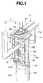
- FIGS. 1 to 7 show a first embodiment of the present invention.
- reference numeral 1 denotes a welding gun mounted on a welding robot.
- the welding gun 1 includes first and second gun arms 2 and 3, and electrode tips 4 and 5 are detachably mounted at both ends of the gun arms 2 and 3 in confrontation with each other. Both the electrode tips 4 and 5 are disposed coaxially and are relatively approached to or separated from each other by the forward or backward movement of at least one of both the gun arms 2 and 3.
- Reference numeral 11 denotes a tip dresser for dressing the ends of the electrode tips 4 and 5.
- the tip dresser 11 is disposed at the position where the tip dresser 11 does not interfere with a welding work within the working range of the welding robot.
- a holder 12 is disposed at the end of a main body 11a extending to a side of the tip dresser 11, and a dressing body 13 is rotatably supported by the holder 12.
- the dressing body 13 is rotated by a servo motor 14 that is suspended from the main body 11a.
- Cutters 13a and 13b each formed in a concave shape are disposed on the upper and lower surfaces of the dressing body 13 so as to dress the ends of the electrode tips 4 and 5 to a predetermined shape by polishing or grinding.
- a lower chip capturing case 15 is mounted on the lower surface of the main body 11a.
- the lower chip capturing case 15 is fixedly disposed to surround the holder 12 that opens to the lower surface of the main body 11a as well as has a chip ejection port 15a formed through the bottom thereof. Further, a tip inserting port 15b is formed on one side of the lower chip capturing case 15.
- a shield member 16 is disposed to the tip inserting port 15b.
- the shield member 16 is composed of a pair of brush units 17 and 18 that are disposed on right and left sides of the tip inserting port 15b in confrontation with each other.
- Brushes 17a and 18a made from nylon are disposed to the respective brush units 17 and 18 respectively, and the roots of the brushes 17a and 18a are clamped and fixed to the edges of the tip inserting port 15b by plates 17b and 18b.
- the ends of the brushes 17a and 18a of the brush units 17 and 18 are abutted against each other approximately at a center of the tip inserting port 15b so as to shield thereof. Further, an upper chip capturing case 19 is mounted on the upper surface of the main body 11a.
- the upper chip capturing case 19 is disposed for surrounding the holder 12 that opens to the upper surface of the main body 11a.
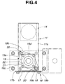
- a diamond-shaped base plate 19a is formed on the bottom of the upper chip capturing case 19, and clamp holes 19b drilled at the edges in a diagonal direction thereof are fixed on the upper surface of the main body 11a by such hooks 20 as bolts.
- both the clamp holes 19b have cutouts formed thereto so that they can be separated from the hooks 20 by turning the base plate 19a to a counterclockwise direction as shown in the figure.
- the upper surface of the upper chip capturing case 19 is closed with a transparent plate 19c composed of resin.
- a tip inserting hole 19d is opened at the center of the transparent plate 19c, and a shield member 21 is disposed in the tip insert hole 19d.
- the shield member 21 is in sliding contact with the outside periphery of the gun arm 3 inserted into the tip inserting hole 19d to close a clearance therebetween and composed of a brush, a rubber plate having flexibility.
- the shield member 21 is not required to have air tightness because it is sufficient for the shield member 21 to prevent chips generated when the electrode tip 5 is dressed from scattering to the outside from the tip insert hole 19d.
- an air nozzle 22 for blowing air to the dressing body 13 is faced to the interior of the transparent plate 19c to prevent the dressing body 13 (refer to FIG. 2) from clogging.
- a chip collection vessel 23 is suspended to the chip ejection port 15a formed through the bottom of the lower chip capturing case 15 by a suspension bolt 24. It is preferable that the chip collection vessel 23 be light in weight.
- the lower portion of a PET bottle (bottle composed of polyethylene terephthalate) the upper portion of which is cut off may be used as the chip collection vessel 23.
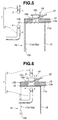
- the first and second gun arms 2 and 3 disposed to the welding gun 1 are moved in a direction of the main body 11a by the welding robot (refer to FIG. 5).
- the first gun arm 2 is inserted into the lower chip capturing case 15 mounted on the lower surface of the main body 11a through the tip inserting port 15b thereof and faced to the interior of the lower chip capturing case 15.
- the tip inserting port 15b is shielded with the brushes 17a and 18a extending from the left and right sides thereof.
- the brushes 17a and 18a are flexed (tortured) along the outside shape of the first gun arm 2 and close the periphery thereof.
- the axial center of the electrode tip 4 disposed at the end of the first gun arm 2 is aligned with the central axis of the dressing body 13 disposed to the holder 12 that is provided with the main body 11a (refer to FIG. 6).
- the electrode tip 4 is disposed coaxially with the electrode tip 5 that is disposed at the end of the second gun arm 3, the axial center of the electrode tip 5 also is aligned with the central axis of the dressing body 13.
- both the gun arms 2 and 3 are moved to cause both the electrode tips 4 and 5 to relatively approach to each other.
- the electrode tip 5 disposed at the end of the second gun arm 3 is faced to the tip inserting hole 19d opened to the transparent plate 19c of the upper chip capturing case 19 that is fixedly disposed on the upper surface of the main body 11a.
- the flexible shield member 21 that is formed in a ring shape is disposed to the tip inserting hole 19d and closes the outside periphery of the second gun arm 3.
- the dressing body 13 is rotated by the servo motor 14 disposed to the dresser main body 11a, and air is blown toward the dressing body 13 from the air nozzle 22 facing the interior of the upper chip capturing case 19.
- the air blown from the air nozzle 22 flows from the upper chip capturing case 19 to the lower chip capturing case 15 and is blown out to the outside from the tip inserting port 15b and the chip ejection port 15a of the lower chip capturing case 15 as shown by arrows in FIG. 7.
- the drive of the dressing body 13 and the blowing air from the air nozzle 22 may be started in synchronism with the detection of a state that the electrode tips 4 and 5 have approached or have been abutted against the dressing body 13.
- the chips are generated when the electrode tips 4 and 5 are polished or ground with the cutters 13a and 13b disposed to the dressing body 13. These chips are introduced to the lower chip capturing case 15 by the air blown from the air nozzle 22 faced to the upper chip capturing case 19. At this time, the chips, which are introduced by the air which leaks from the tip insertion port 15b, collide with the brushes 17a and 18a disposed to the tip inserting port 15b and are dropped into the lower chip capturing case 15.
- the chips having been dropped into the lower chip capturing case 15 are accumulated in the chip collection vessel 23 suspended to the chip ejection port 15a formed through the bottom of the lower chip capturing case 15.
- the first and second gun arms 2 and 3 are separated from the main body 11a through a movement opposite to that when they were inserted and caused to wait for the next spot welding.
- the chips accumulated in the chip collection vessel 23 reach a predetermined amount, they are collected and reused. Otherwise, these are collected and reused periodically.
- the chips generated in the dressing operation movement are not dispersed to the outside and can be effectively collected in the chip collection vessel 23 and reused, whereby a chip reuse ratio can be improved.
- the air is utilized to prevent the dressing body 13 from clogging and the chips are positively introduced in a direction of the chip ejection port 15a formed through the bottom of the lower chip capturing case 15, the chip collection efficiency of collecting chips can be more improved. Further, since an existing air blow device can be utilized as it is as the air blow device, cost of equipment can be suppressed.
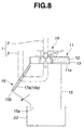
- FIG. 8 shows a second embodiment of the present invention.
- the tip inserting port 15b disposed to the lower chip capturing case 15 is opened obliquely upward.
- the chips dropping downward are unlike to leak to the outside through the brushes 17a and 18a disposed to the tip inserting port 15b, whereby the chip collection efficiency of the chips collected by the chip collection vessel 23 can be more improved.
- FIGS. 9 to 17 show a third embodiment of the present invention.
- the dressing body 13 exposed to the upper and lower surfaces of the main body 11a is separately covered with the upper and lower chip capturing cases 19 and 15.
- the end of the main body 11a is inserted into a single chip capturing case 25, and the interior of the chip capturing case 25 is partitioned into an upper chamber 25e and a lower chamber 25f by the main body 11a.
- the chip capturing case 25 is mounted at the end of the main body 11a extending to a side of the tip dresser 11.
- the chip capturing case 25 is formed by processing a thin steel sheet, and the upper surface thereof inclines obliquely upward in a backward direction.
- a tip inserting port 25a having a predetermined width is opened from the front surface to the upper surface of the chip capturing case 25.
- a hole 25b is opened through the back surface of the chip capturing case 25 at a upper portion thereof so that the end of the main body 11a is inserted therethrough, whereas the bottom 25c of the chip capturing case 25 is formed as an inclined surface that inclines from the front surface to the back surface of the case 25.
- a chip ejection port 25d is formed to the inclined surface of the bottom 25c on a lower side thereof.
- the upper end of the chip collection vessel 23 is suspended to the chip ejection port 25d through the suspension bolt 24.
- a pet bottle or the like subjected to predetermined processing may be diverted as the chip collection vessel 23 similarly to the first embodiment.
- a shield member 29 is fixedly disposed to the tip inserting port 25a of the chip capturing case 25.
- the shield member 29 is composed of a pair of brush units 30 and 31 disposed on the right and left sides of the tip inserting port 25a in confrontation with each other.
- Brushes 30a and 31a composed (made from) nylon are disposed to the respective brush units 30 and 31, and the roots of the brushes 30a and 31a are clamped and fixed to the edges of the tip inserting port 25b by plates 30b and 31b.
- the tip insertion port 25a is entirely covered with the brush units 30 and 31 over the front surface and the upper surface thereof, whereby the chips generated when the electrode tips 4 and 5 are dressed can be prevented from dispersing to the outside from the tip inserting port 25a.
- support plates 26 are disposed to the hole 25b opened through the back surface of the chip capturing case 25 at the four corners on the upper and lower sides thereof.
- the front ends of the respective support plates 26 horizontally extend in a direction of the tip inserting port 25a, the extreme ends of the respective support plates 26 are welded to the edges of the tip inserting port 25a on the inner surface side thereof, and further the portions of the support plates 26 in contact with the hole 25b are welded thereto.
- the main body 11a When the end of the main body 11a is inserted into the hole 25b, the main body 11a is positioned with the upper and lower edges thereof supported by the support plates 26, the interior of the chip capturing case 25 is partitioned into the upper chamber 25e and the lower chamber 25f, and the upper and lower surfaces of the dressing body 13 supported by the holder 12 disposed at the end of the main body 11a are exposed to the upper and lower chambers 25e and 25f, respectively.
- the rear portions of the support plates 26 project to the outside from the hole 25b, and a pair of fixing blocks 32 are abutted against the projecting portions from the upper and lower sides thereof. Both ends of the fixing blocks 32 are tightened by bolts 33 so that they are clamped and fixed to the main body 11a. Further, the fixing blocks 32 are positioned to the main body 11a by screws 34 (refer to FIG. 13) passing through the fixing blocks 32 at the center thereof.
- cutouts are formed to the portions of the main body 11a through which the bolts 33 pass.
- an air nozzle 35 is fixed to the back surface of the upper chamber 25e of the chip capturing case 25, and the end of the air nozzle 35 is directed toward the dressing body 13 exposed to the upper chamber 25e.
- the chips deposited (adhered) on the dressing body 13 are blown off by the air blown from the air nozzle 35 so as to prevent the dressing body 13 from clogging.
- cavities 36a, 36b, and 36c are formed between the inner wall of the chip capturing case 25 and the end and both the sides of the main body 11a, and the upper chamber 25e communicates with the lower chamber 25f through the cavities 36a, 36b, and 36c and a clearance formed to the dressing body 13.
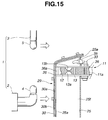
- the first and second gun arms 2 and 3 disposed to the welding gun 1 are moved in a direction of the main body 11a by the welding robot in a state that the gun arm 2 is separated from the second gun arm 3 by a predetermined distance (refer to FIG. 15).
- chip capturing case 25 is mounted on and fixed to the end of the main body 11a, and the front and upper surfaces of the chip capturing case 25, to which the gun arms 2 and 3 are faced, are shielded with the brushes 30a and 31a.
- both the gun arms 2 and 3 are approached to the front surface of the chip capturing case 25, the first gun arm 2 is caused to pass through the brushes 30a and 31a so as to face the lower chamber 25f of the chip capturing case 25 as well as the second gun arm 3 is disposed above the chip capturing case 25.
- the axial center of the electrode tip 4 disposed at the end of the first gun arm 2 is aligned with the central axis of the dressing body 13 disposed to the holder 12 that is provided with the main body 11a (refer to FIG. 16).
- the electrode tip 4 since the electrode tip 4 is disposed coaxially with the electrode tip 5 that is disposed at the end of the second gun arm 3, the electrode tip 5 also is aligned with the central axis of the dressing body 13.
- both the gun arms 2 and 3 are moved to cause both the electrode tips 4 and 5 to relatively approach to each other.
- the electrode tip 5 disposed at the end of the second gun arm 3 first passes through the brushes 30a and 31a from the upper surface of the main body 11a and is faced to the upper chamber 25e.
- the brushes 30a and 31a are elastically deformed (distorted) along the outside shape of the second gun arm 3 and close the periphery thereof.
- the dressing body 13 is rotated by the servo motor 14 disposed to the main body 11a, and air is blown to the dressing body 13 from the air nozzle 35 facing the upper chamber 25e.
- the chips deposited on the dressing body 13 are blown off by the air.
- the air blown to the dressing body 13 flows to the lower chamber 25f through the clearance of the dressing body 13 and the cavities 36a, 36b, and 36c secured around the periphery of the main body 11a and is blown out to the outside from the brushes 30a and 31a closing the front surface of the lower chamber 25f and from the chip ejection port 25d opened through the bottom 25c of the lower chamber 25f.
- the drive of the dressing body 13 and the blow of the air from the air nozzle 35 may be started in synchronism with the detection of a state that the electrode tips 4 and 5 have approached or have been abutted against the dressing body 13.
- the chips which are generated when the electrode tips 4 and 5 are dressed by polishing or grinding with the cutters 13a and 13b mounted on the dressing body 13, are introduced to the lower chamber 25f by the air blown from the air nozzle 35 facing the upper chamber 25e.
- the chips which have been dropped onto the bottom 25c of the lower chamber 25f, pass through the chip ejection port 25d and are accumulated in the chip collection vessel 23 suspended to the chip ejection port 25d.
- the first and second gun arms 2 and 3 are separated by the welding robot from the main body 11a through an operation movement opposite to that when these were inserted and caused to wait for the next spot welding.
- the chips generated in an dressing operation are not dispersed to the outside and can be effectively collected in the chip collection vessel 23, whereby the chip reuse ratio can be improved.
- the air is utilized to prevent the dressing body 13 from clogging and chips are positively introduced in a direction of the bottom 25c of the lower chamber 25f, the chip collection efficiency can be more improved. Further, since an existing air blow device can be utilized as it is as the air blow device, cost of the equipment can be suppressed (reduced).
- the tip inserting ports 15b and 19d, into which the first and second gun arms 2 and 3 are inserted, are shielded with the brushes 30a and 31a, no chip is scattered, whereby the chips can be collected very effectively. Further, since the brushes 30a and 31a are continuously disposed from the front surface of the chip capturing case 25 to the upper surface thereof, when the gun arms 2 and 3 are faced to the chip capturing case 25, it is not necessary to correctly align them with the chip capturing case 25, which improves workability.
- the air blown out from the air nozzle 35 is introduced from the upper chamber 25e to the lower chamber 25f through not only the clearance of the dressing body 13 but also through the cavities 36a, 36b, and 36c secured around the periphery of the main body 11a.
- the air can easily be supplied from the upper chamber 25e to the lower chamber 25f, which permits the chips scattered in the upper chamber 25e to be promptly introduced into the lower chamber 25f.
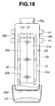
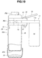
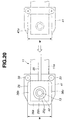
- FIGS. 18 to 22 show a fourth embodiment of the present invention.
- the chip capturing case 25 is made by blow-molding. As shown in FIG. 21, the chip capturing case 25 is formed in a simple rectangular-prism-shape, and a projection 25g is formed integrally therewith when the case 25 is made by the blow-molding.
- a tip insertion port 25h is formed through the projection 25g; the tip insertion port 25a is formed through the front surface of the chip capturing case 25, the hole 25b, and a hole 25i through which an air nozzle 35 is mounted are formed through the back surface thereof; and further the chip ejection port 25d is formed through the bottom thereof in post processing, respectively.
- a ring-shaped, flexible and heat resistant shield member 42 is fixedly disposed to the tip insertion port 25h by such as adhesion bonding.
- the heat resistant shield member 42 slidably contacts with the outside periphery of the gun arm 3 that is inserted into the tip inserting hole 25h and closes the clearance between the outside periphery of the gun arm 3 and the tip insert hole 25h.
- the heat resistant shield member 42 is composed of silicon rubber, or the like.
- the chip capturing case 25 is made by the blow-molding of resin materials, the weight thereof can be reduced and the structure thereof can be simplified as well as the economical efficiency and the mass-productivity thereof can be improved.
- an electrode tip dressing apparatus can be more practically usably arranged by giving the highest priority to the breakage of the less expensive resin product in the occurrence of the collision of the apparatus due to control mistakes of the robot so that an adverse effect applied to the robot and the main body 11a can be minimized.
- first, holding blocks 41 are fixedly disposed to the upper and lower surfaces of the main body 11a.
- the end of the main body 11a is inserted into the hole 25b formed through the back surface of the chip capturing case 25.
- the recessed portions of fork-shaped members 41a formed at the ends of the holding blocks 41 are fitted on the outside surface of the chip capturing case 25.
- each fork-shaped member 41a Since the interval W' of each fork-shaped member 41a is formed slightly smaller than the width W between the sides of the chip capturing case 25, the chip capturing case 25 is held by the elastic deformation of the fork-shaped members 41a when fitted on the chip capturing case 25.
- the cavities 36a, 36b, and 36c are formed around the end of the main body 11a in the chip capturing case 25.
- the chips generated when dressing are introduced downward through the clearance of the dressing body 13 and the cavities 36a, 36b, and 36c secured around the main body 11a and accumulated in the chip collection vessel 23, similarly to the third embodiment.
- the reduction in weight of the chip capturing case 25 and the simplified structure thereof can be realized by the blow-molding. Further, since the tip inserting port 25h is shielded with the heat-resistant shield member 42, which is not easily deformed and broken by a friction heat generated when the electrode tip 5 is dressed, whereby the heat resistance of the chip capturing case 25 can be improved.
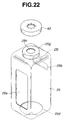
- a heat resistant and flexible shield member 43 may be formed in a cap shape and fitted to the projection 25g from the outside as shown in FIG. 22.
- the formation of the shield member 43 in the cap shape permits it to be easily replaced.
- a hole formed at the center of the shield member 43 may be post processed according to the size of the electrode tip 5, and the versatility of the shield member 43 can be increased by the post processing.
- FIGS. 23 to 27 show a fifth embodiment of the present invention.
- a lower chip capturing case 57 is turnably supported on the lower surface of the main body 11a.
- a support plate 55 is fixedly disposed to the lower surface of the main body 11a extending in a side direction of the tip dresser 11 at a portion thereof where the dresser 13 is exposed.
- a hole for escaping from the dressing body 13 is formed to the support plate 55 at a portion thereof corresponding to the dressing body 13, and further a boss 56 projects so as to surround the hole.
- a ring member 58 which is fixedly disposed on the upper surface of the lower chip capturing case 57, is fitted on the boss 56.
- Screws 59 are threaded into the ring member 58 from four directions, and tightening the screws 59 to the boss 56 causes the ring member 58 to be fixed to the boss 56, and the lower chip capturing case 57 is suspended by the boss 56.
- a hole having a diameter approximately the same as the inside diameter of the ring member 58 is formed to the upper surface of the lower chip capturing case 57 at a portion thereof corresponding to the ring member 58, and further a chip ejection port 57a is formed to the bottom of the lower chip capturing case 57. Further, a tip insertion port 57b is formed through the front surface of the lower chip capturing case 57.
- a shield member 60 is disposed to the tip insertion port 57b.
- the shield member 60 is composed of a pair of brush units 61 and 62 that are disposed on the right and left sides of the tip inserting port 57b in confrontation with each other.
- Brushes 61a and 62a each composed nylon are disposed to the respective brush units 61 and 62, and the roots of the brushes 61a and 62a are clamped and fixed to the edges of the tip inserting port 57b by plates 61b and 62b.
- the shield member 60 is not required to have air tightness because it is used to prevent the chips generated when the electrode tips 4 and 5 are dressed from scattering to the outside from the tip insertion port 57b.
- the ends of the brushes 61a and 62a of the brush units 61 and 62 are abutted against each other approximately at the center of the tip inserting port 57b so as to shield it.
- an upper chip capturing case 63 is mounted on the upper surface of the main body 11a.
- the upper chip capturing case 63 is disposed so as to surround the holder 12 that opens to the upper surface of the main body 11a.
- a flange 63a is formed on the bottom of the upper chip capturing case 63, and an upper surface shield member 65 is clamped and fixed to the upper surface thereof through an upper plate 63b.
- the flange 63a is fixedly disposed to a base plate 64, which is fixedly disposed to the main body 11a, through bolts.
- the upper shield member 65 slidably contacts with the outside periphery of the gun arm 3 inserted into a tip inserting port 63c opened through the upper surface of the upper chip capturing case 63 so as to close the clearance between the outside periphery of the gun arm 3 and the tip inserting port 63c.
- the upper shield member 65 is composed of a flexible member such as a ring-shaped rubber plate, radially disposed brushes.
- the upper shield member 65 is not required to have air tightness because it is sufficient for the shield member 65 to prevent the chips generated when the electrode tip 5 is dressed from scattering to the outside from the tip inserting hole 63c.
- an air nozzle 67 for blowing air to the dressing body 13 is faced to the interior of the upper chip capturing case 63 to prevent the dressing body 13 from clogging.
- the upper end of the chip collection vessel 23 is suspended to the chip ejection port 57a formed through the bottom of the lower chip capturing case 57 through the suspension bolt 24.
- the pet bottle subjected to the predetermined processing may be diverted as the chip collection vessel 23 similarly to the first embodiment.
- the ring member 58 which projects from the upper surface of the lower chip capturing case 57, is fitted on the boss 56 disposed to the support plate 55 which is fixedly disposed to the lower surface of the main body 11a.
- the lower chip capturing case 57 is positioned and fixed by tightening the screws 59 which are threaded into the ring member 58 from the four directions and by pressing the ends thereof against the boss 56 in a state in which the front surface of the lower chip capturing case 57, that is, the surface thereof through which the tip inserting port 57b is opened is directed in the advancing direction of the gun arm 2.
- the first and second gun arms 2 and 3 disposed to the welding gun 1 are moved in a direction of the main body 11a by the welding robot.
- the first gun arm 2 is inserted into the lower chip capturing case 57 mounted on the lower surface of the dresser main body 11a through the tip inserting port 57b thereof and faced to the interior of the lower chip capturing case 57.
- the gun arm 2 can be smoothly introduced into the lower chip capturing case 57 because the tip inserting port 57b of the lower chip capturing case 57 is previously adjusted in the advancing direction of the gun arm 2.
- the tip inserting port 57b is shielded with the brushes 61a and 62a extending from the right and left sides thereof, and when the first gun arm 2 is inserted into the tip inserting port 57b, the brushes 61a and 62a are elastically deformed along the outside periphery of the first gun arm 2 and closes the periphery thereof.
- the axial center of the electrode tip 4 disposed at the end of the first gun arm 2 is aligned with the central axis of the dressing body 13 held by the holder 12 provided with the main body 11a.
- the electrode tip 4 is disposed coaxially with the electrode tip 5 disposed at the end of the second gun arm 3, the axial center of the electrode tip 5 is also aligned with the central axis of the dressing body 13.
- both the gun arms 2 and 3 are moved to cause both the electrode tips 4 and 5 to relatively approach to each other.
- the electrode tip 5 disposed at the end of the second gun arm 3 is inserted into the tip inserting port 63c opened through the upper surface of the upper chip capturing case 63.
- the upper flexible shield member 65 is disposed on the upper surface of the tip inserting port 63c, and the outside periphery of the second gun arm 3 is shielded with the upper shield member 65.
- both the electrode tips 4 and 5 are abutted against the cutters 13a and 13b disposed to the lower and upper surfaces of the dressing body 13, respectively, and the dressing body 13 is clamped under pressure between both the electrode tips 4 and 5.
- the dressing body 13 is rotated or swung by the servo motor 14 disposed to the main body 11a, and the air is blown toward the dressing body 13 from an air nozzle 67 faced to the interior of the upper chip capturing case 63.
- the air blown from the air nozzle 67 flows from the interior of the upper chip capturing case 63 to the lower chip capturing case 57 through the clearance formed between the holder 12 and the dressing body 13.
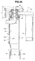
- the air is blown out to the outside from the tip insertion port 57b of the lower chip capturing case 57 and from the chip ejection port 57a formed through the bottom thereof as shown by arrows in FIG. 26.
- the rotational drive (or swing drive) of the dressing body 13 and the air blowing from the air nozzle 67 may be started in synchronism with the detection of a state that the electrode tips 4 and 5 have approached or have been abutted against the dressing body 13.
- the chips which are generated when the electrode tips 4 and 5 are dressed by polishing or grinding with the cutters 13a and 13b mounted on the dressing body 13, are introduced to the lower chip capturing chamber 57 by the air blown from the air nozzle 67 faced to the upper chip capturing case 63.
- the chips which are introduced by the air leaked from the tip inserting port 57b, collide with the brushes 61a and 62a disposed to the tip inserting port 57b and are dropped into the lower chip capturing case 57.
- the chips which have been dropped into the lower chip capturing case 57, are deposited in the chip collection vessel 23 which is suspended to the chip ejection port 57a formed through the bottom of the lower chip capturing case 57.
- the first and second gun arms 2 and 3 are separated by the welding robot from the main body 11a through an operation opposite to that when inserted and caused to wait for the next spot welding.
- the lower chip capturing case 57 is turnably (rotatably) supported by the main body 11a so that the surface thereof through which the tip inserting port 57b is opened can be fixed in a state in which the surface is directed to the advancing direction of the gun arm 2. Accordingly, the gun arm 2 can be smoothly introduced into the lower chip capturing case 57, which provides the allowance for the direction of the lower chip capturing case 57 when it is installed.
- the lower and upper surfaces of the dressing body 13 are surrounded with the lower and upper chip capturing case 57 and 63 and the electrode tips 4 and 5 are dressed in both the cases 57 and 63, the chips generated while the dressing operations are not dispersed to the outside and can be effectively collected in the chip collection vessel 23 and reused, whereby the chip reuse ratio can be improved.
- the air is utilized to prevent the dressing body 13 from clogging and the chips are positively introduced to the chip ejection port 57a of the lower chip capturing case 57, the chip collection efficiency can be more improved. Further, as an existing air blowing device can be utilized, the cost of equipments can be suppressed (reduced).
- the lower chip capturing case 57 is arranged as the injection molded product or as the integrally molded product which is made by forming necessary portions such as the tip inserting ports to the blow-molded product by post processing, the weight of the lower chip capturing case 57 can be reduced and the structure thereof can be simplified as well as the economical efficiency thereof can be improved and the mass-production can be easily attained.
- an electrode tip dressing apparatus can be more practically usably arranged by giving the highest priority to the breakage of the less expensive molded product in the occurrence of the collision of the apparatus due to a false teaching to the robot so that the adverse effect applied to the robot and the main body 11a can be minimized.
- the lower chip capturing case 57 may be positioned and fixed in such a manner that a metal ring is inserted to or fitted on the ring member 58 and the ring member 58 is fixed to the boss 56 by screws through the metal ring.
- FIG. 28 shows a sixth embodiment of the present invention.
- a tip insertion port (not shown) is opened through the upper chip capturing case 63 in an inclining attitude, the brushes 71a and 72a of brush units 71 and 72 are disposed to the tip insertion port in confrontation with each other so as to joint at a center, and the roots of the brushes 71a and 72a are fixed by plates 71b and 72b.
- the electrode tip 5 fixed at the end of the second gun arm 3 can be easily introduced into the upper chip capturing case 63 even if the stroke between the gun arms 2 and 3 is relatively short.
- FIG. 29 and 30 show a seventh embodiment of the present invention.
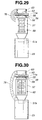
- the interior of the upper chip capturing case 63 is communicated with the upper or lower portion of the lower chip capturing case 57 through a flexible chip ejection path 76 such as a flexible hose that can permit the lower chip capturing case 57 to turn.
- a flexible chip ejection path 76 such as a flexible hose that can permit the lower chip capturing case 57 to turn.
- the chips floating in the upper side of the chip capturing case 63 are ejected to the lower chip capturing case 57 through the chip ejection path 76, the chips do not deposit on the dressing body and the drive mechanism connecting to the dressing body, whereby a malfunction in operation can be effectively avoided and the maintenance can be effectively carried out.
- the upper surface of the lower chip capturing case 57 may be turnably (or rotatably) connected to the lower surface of the dresser main body 11a through a radial bearing so that the lower chip capturing case 57 can be positioned by being pressed and fixed using a screw at one position.
- the present invention is by no means limited to the aforementioned embodiments.
- the shield members 16, 29, 60, and 65 need not be composed of the brushes and, any member such as a rubber plate may be used as long as it can shield the tip insertion ports 15b, 25a, and 57a while permitting the insertion and the removal of the gun arms 2 and 3 into and from the tip inserting ports 15b, 25a, and. 57b as well as it has a restoring (reproduction) property.
- the chip collection vessel 23 may be disposed below the chip ejection ports 15a, 25d, and 57a disposed to the chip capturing cases 15, 25, and 57 and an ejection path may be connected to the chip ejection port 15a, 57a or 25d so as to drop the chips from the chip ejection port 15a, 57a, or 25d to the chip collection vessel 23 through the ejection path.
- the chip collection ratio of the chips which are generated when the electrode tips are dressed by polishing or grinding can be increased, whereby the chip reusable ratio can be improved.
Landscapes
- Engineering & Computer Science (AREA)
- Mechanical Engineering (AREA)
- Resistance Welding (AREA)
- Arc Welding In General (AREA)
- Grinding-Machine Dressing And Accessory Apparatuses (AREA)
Abstract
Description
- The present invention relates to an electrode tip dressing apparatus of welding machines capable of effectively collecting chips generated when an electrode tip is dressed.
- Hitherto, an electrode tip used for spot welding is worn (subjected to deformation and abrasion) when a welding work is repeatedly carried out by using the electrode tip. When the welding work is executed by using a worn electrode tip, a desired quality of the welding work cannot be obtained. Thus, the electrode tip is periodically cleaned by dressing to maintain the quality of the welding work.
- For example, Japanese Patent Unexamined Publication No. 6-122082 discloses an art for dressing electrode tips in such a manner that the upper and lower surfaces of a dresser are clamped under a pressure between a pair of electrode tips oppositely disposed at both ends of a welding gun and then the electrode tips are dressed by polishing when the welding gun is swung about an axial center of the electrode tips.
- By the way, it is recently studied to recycle the chips from a view point of reducing a material cost and environmental problems. For this purpose, a collection vessel is disposed below the dresser so as to reuse the chips collected in the collection vessel.
- However, since the chip is liable to be scattered by relative swing motions between the dresser and the electrode tip or by a rotation thereof in a polishing work, all the chips can not be collected in the collection vessel, which causes problems that a chip collection efficiency is low.
- Moreover, when air is blown to the dresser to prevent the chips from clogging therein, the chips are scattered by the air blown thereto, which further reduces the chip collection efficiency.
- Incidentally, a copper is often as used as a material of the electrode tip for the spot welding. However, the electrode tip is ground more frequently to maintain a proper quality of the welding works, and an amount of ground or polished chips of the electrode tip is increased thereby. Thus, it is necessary to increase a chip collection rate (efficiency) and to effectively reuse the chips to reduce a material cost.
- An object of the present invention is to provide a newly-developed electrode tip dressing apparatus capable of increasing a collection rate of chips which are generated when an electrode tip is dressed by polishing or grinding and of improving a recycle rate of the chips.
- An electrode tip dressing apparatus of the present invention for dressing a pair of electrode tips arranged in confrontation with each other includes a dressing body having upper and lower surfaces clamped under pressure by said pair of electrode tips for dressing said pair of electrode tips through a relatively sliding motion thereof with said electrode tips; a chip capturing case for covering said dressing body and having a tip inserting port through which at least one of said electrode tips is inserted; and a shield member disposed to the tip inserting port of said chip capturing case.
- According to this arrangement, the dressing body is covered with the chip capturing cases, the tip insertion ports into which the electrode tips are inserted are formed to the chip capturing cases, and the shield members are disposed to the tip insertion ports. Accordingly, the chips generated when the electrode tips are dressed can be collected in the chip capturing cases without scattering them to the outside.
- The above and other objects, features and advantages of the invention will become more clearly understood from the following description referring to the accompanying drawings.
-
- FIGS. 1 to 7 relate to a first embodiment of the present invention, wherein:
- FIG. 1 is a perspective view of an electrode tip dressing apparatus;
- FIG. 2 is a front elevational view of the electrode tip dressing apparatus;
- FIG. 3 is a sectional view of the electrode tip dressing apparatus taken along the line III-III of FIG. 2;
- FIG. 4 is a plan view of the electrode tip dressing apparatus shown in FIG. 2;
- FIG. 5 is a view explaining a state in which welding gun arms are moved to the electrode tip dressing apparatus;
- FIG. 6 is a view explaining a state in which the gun arms are faced to a lower case;
- FIG. 7 is a view showing a state when the electrode tips are dressed;
- FIG. 8 is a view explaining a state when the electrode tips are dressed by a second embodiment of the present invention.
- FIGS. 9 to 17 relate to a third embodiment of the present invention, wherein:
- FIG. 9 is a perspective view of the electrode tip dressing apparatus;
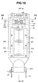
- FIG. 10 is a front elevational view of the electrode tip dressing apparatus;
- FIG. 11 is a sectional view of the electrode tip dressing apparatus taken along the line XI-XI of FIG. 10;
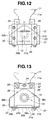
- FIG. 12 is a plan view of the electrode tip dressing apparatus;
- FIG. 13 is a sectional view of the electrode tip dressing apparatus taken along the line XIII-XIII of FIG. 10;
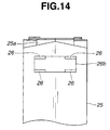
- FIG. 14 is a rear elevational view of the main portion of a chip capturing case;
- FIG. 15 is a view explaining a state in which the gun arms are moved to the electrode tip dressing apparatus;
- FIG. 16 is a view explaining a state in which the gun arms are faced to the chip capturing case;
- FIG. 17 is a view explaining a state in which the electrode tips are dressed;
- FIGS. 18 to 22 relate to a fourth embodiment of the present invention, wherein:
- FIG. 18 is a front elevational view of the electrode tip dressing apparatus;
- FIG. 19 is side elevational, view partly in cross section, of the electrode tip dressing apparatus;
- FIG. 20 is a plan view of the electrode tip dressing apparatus;
- FIG. 21 is perspective view of a chip capturing case;
- FIG. 22 is perspective view of the chip capturing case according to a different mode;
- FIGS. 23 to 27 relate to a fifth embodiment of the present invention, wherein:
- FIG. 23 is a perspective view of the electrode tip dressing apparatus;
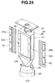
- FIG. 24 is an exploded perspective view of the main portion of the electrode tip dressing apparatus;
- FIG. 25 is a front elevational view of the electrode tip dressing apparatus;
- FIG. 26 is a sectional view taken along the line XXVI-XXVI of FIG. 25;
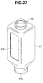
- FIG. 27 is a perspective view of the lower case according to another mode;
- FIG. 28 is an exploded perspective view of the electrode tip dressing apparatus according to a sixth embodiment;
- FIGS. 29 and 30 relate to a seventh embodiment of the present invention, wherein:
- FIG. 29 is a schematic view of the electrode tip dressing apparatus; and
- FIG. 30 is a schematic view of the electrode tip dressing apparatus according to a different mode.
-
- FIGS. 1 to 7 show a first embodiment of the present invention.
- In the figure,
reference numeral 1 denotes a welding gun mounted on a welding robot. Thewelding gun 1 includes first andsecond gun arms electrode tips gun arms electrode tips gun arms -
Reference numeral 11 denotes a tip dresser for dressing the ends of theelectrode tips tip dresser 11 is disposed at the position where thetip dresser 11 does not interfere with a welding work within the working range of the welding robot. - A
holder 12 is disposed at the end of amain body 11a extending to a side of thetip dresser 11, and a dressingbody 13 is rotatably supported by theholder 12. The dressingbody 13 is rotated by aservo motor 14 that is suspended from themain body 11a.Cutters body 13 so as to dress the ends of theelectrode tips - Further, a lower
chip capturing case 15 is mounted on the lower surface of themain body 11a. The lowerchip capturing case 15 is fixedly disposed to surround theholder 12 that opens to the lower surface of themain body 11a as well as has achip ejection port 15a formed through the bottom thereof. Further, atip inserting port 15b is formed on one side of the lowerchip capturing case 15. - A
shield member 16 is disposed to thetip inserting port 15b. Theshield member 16 is composed of a pair ofbrush units tip inserting port 15b in confrontation with each other.Brushes respective brush units brushes tip inserting port 15b byplates - Note that air tightness is not required to the
shield member 16 because it is used to prevent the chips generated when theelectrode tips tip insertion port 15b. - As shown in FIGS. 1 and 2, the ends of the
brushes brush units tip inserting port 15b so as to shield thereof. Further, an upperchip capturing case 19 is mounted on the upper surface of themain body 11a. - The upper
chip capturing case 19 is disposed for surrounding theholder 12 that opens to the upper surface of themain body 11a. As shown in FIG. 4, a diamond-shapedbase plate 19a is formed on the bottom of the upperchip capturing case 19, and clampholes 19b drilled at the edges in a diagonal direction thereof are fixed on the upper surface of themain body 11a bysuch hooks 20 as bolts. As shown in the figure, both the clamp holes 19b have cutouts formed thereto so that they can be separated from thehooks 20 by turning thebase plate 19a to a counterclockwise direction as shown in the figure. - The upper surface of the upper
chip capturing case 19 is closed with atransparent plate 19c composed of resin. Atip inserting hole 19d is opened at the center of thetransparent plate 19c, and ashield member 21 is disposed in thetip insert hole 19d. Theshield member 21 is in sliding contact with the outside periphery of thegun arm 3 inserted into thetip inserting hole 19d to close a clearance therebetween and composed of a brush, a rubber plate having flexibility. - Note that the
shield member 21 is not required to have air tightness because it is sufficient for theshield member 21 to prevent chips generated when theelectrode tip 5 is dressed from scattering to the outside from thetip insert hole 19d. - Further, an
air nozzle 22 for blowing air to the dressingbody 13 is faced to the interior of thetransparent plate 19c to prevent the dressing body 13 (refer to FIG. 2) from clogging. - In contrast, the upper end of a
chip collection vessel 23 is suspended to thechip ejection port 15a formed through the bottom of the lowerchip capturing case 15 by asuspension bolt 24. It is preferable that thechip collection vessel 23 be light in weight. For example, the lower portion of a PET bottle (bottle composed of polyethylene terephthalate) the upper portion of which is cut off may be used as thechip collection vessel 23. - Next, processes for dressing the
electrode tips - When the ends of the
electrode tips second gun arms welding gun 1 are moved in a direction of themain body 11a by the welding robot (refer to FIG. 5). - Next, the
first gun arm 2 is inserted into the lowerchip capturing case 15 mounted on the lower surface of themain body 11a through thetip inserting port 15b thereof and faced to the interior of the lowerchip capturing case 15. Thetip inserting port 15b is shielded with thebrushes first gun arm 2 is inserted through thetip inserting port 15b, thebrushes first gun arm 2 and close the periphery thereof. - Then, the axial center of the
electrode tip 4 disposed at the end of thefirst gun arm 2 is aligned with the central axis of the dressingbody 13 disposed to theholder 12 that is provided with themain body 11a (refer to FIG. 6). At this time, since theelectrode tip 4 is disposed coaxially with theelectrode tip 5 that is disposed at the end of thesecond gun arm 3, the axial center of theelectrode tip 5 also is aligned with the central axis of the dressingbody 13. - Thereafter, both the
gun arms electrode tips electrode tip 5 disposed at the end of thesecond gun arm 3 is faced to thetip inserting hole 19d opened to thetransparent plate 19c of the upperchip capturing case 19 that is fixedly disposed on the upper surface of themain body 11a. - The
flexible shield member 21 that is formed in a ring shape is disposed to thetip inserting hole 19d and closes the outside periphery of thesecond gun arm 3. - Then, when the
electrode tips cutters body 13, respectively, and the dressingbody 13 is clamped under pressure therebetween. - The dressing
body 13 is rotated by theservo motor 14 disposed to the dressermain body 11a, and air is blown toward the dressingbody 13 from theair nozzle 22 facing the interior of the upperchip capturing case 19. The air blown from theair nozzle 22 flows from the upperchip capturing case 19 to the lowerchip capturing case 15 and is blown out to the outside from thetip inserting port 15b and thechip ejection port 15a of the lowerchip capturing case 15 as shown by arrows in FIG. 7. - Note that the drive of the dressing
body 13 and the blowing air from theair nozzle 22 may be started in synchronism with the detection of a state that theelectrode tips body 13. - Then, the chips are generated when the
electrode tips cutters body 13. These chips are introduced to the lowerchip capturing case 15 by the air blown from theair nozzle 22 faced to the upperchip capturing case 19. At this time, the chips, which are introduced by the air which leaks from thetip insertion port 15b, collide with thebrushes tip inserting port 15b and are dropped into the lowerchip capturing case 15. - Thereafter, the chips having been dropped into the lower
chip capturing case 15 are accumulated in thechip collection vessel 23 suspended to thechip ejection port 15a formed through the bottom of the lowerchip capturing case 15. - In contrast, when the
electrode tips second gun arms main body 11a through a movement opposite to that when they were inserted and caused to wait for the next spot welding. - When the chips accumulated in the
chip collection vessel 23 reach a predetermined amount, they are collected and reused. Otherwise, these are collected and reused periodically. - As described above, according to this embodiment, since the lower and upper surfaces of the dressing
body 13 are surrounded with the lower and upperchip capturing cases electrode tips cases chip collection vessel 23 and reused, whereby a chip reuse ratio can be improved. - In this case, since the air is utilized to prevent the
dressing body 13 from clogging and the chips are positively introduced in a direction of thechip ejection port 15a formed through the bottom of the lowerchip capturing case 15, the chip collection efficiency of collecting chips can be more improved. Further, since an existing air blow device can be utilized as it is as the air blow device, cost of equipment can be suppressed. - In addition, since the
tip insertion ports second gun arms shield members - FIG. 8 shows a second embodiment of the present invention.
- In this embodiment, the
tip inserting port 15b disposed to the lowerchip capturing case 15 is opened obliquely upward. - With the
tip inserting port 15b directed obliquely upward, the chips dropping downward are unlike to leak to the outside through thebrushes tip inserting port 15b, whereby the chip collection efficiency of the chips collected by thechip collection vessel 23 can be more improved. - FIGS. 9 to 17 show a third embodiment of the present invention.
- In the aforementioned first embodiment, the dressing
body 13 exposed to the upper and lower surfaces of themain body 11a is separately covered with the upper and lowerchip capturing cases main body 11a is inserted into a singlechip capturing case 25, and the interior of thechip capturing case 25 is partitioned into anupper chamber 25e and alower chamber 25f by themain body 11a. - The
chip capturing case 25 is mounted at the end of themain body 11a extending to a side of thetip dresser 11. Thechip capturing case 25 is formed by processing a thin steel sheet, and the upper surface thereof inclines obliquely upward in a backward direction. Atip inserting port 25a having a predetermined width is opened from the front surface to the upper surface of thechip capturing case 25. - Further, a
hole 25b is opened through the back surface of thechip capturing case 25 at a upper portion thereof so that the end of themain body 11a is inserted therethrough, whereas the bottom 25c of thechip capturing case 25 is formed as an inclined surface that inclines from the front surface to the back surface of thecase 25. Achip ejection port 25d is formed to the inclined surface of the bottom 25c on a lower side thereof. - The upper end of the
chip collection vessel 23 is suspended to thechip ejection port 25d through thesuspension bolt 24. A pet bottle or the like subjected to predetermined processing may be diverted as thechip collection vessel 23 similarly to the first embodiment. - In contrast, a
shield member 29 is fixedly disposed to thetip inserting port 25a of thechip capturing case 25. Theshield member 29 is composed of a pair ofbrush units tip inserting port 25a in confrontation with each other.Brushes respective brush units brushes tip inserting port 25b byplates - The
tip insertion port 25a is entirely covered with thebrush units electrode tips tip inserting port 25a. - As shown in FIGS. 9, 10, and 13, the ends of the
brushes respective brush units tip inserting port 25a approximately at the center in the width direction thereof. - Further,
support plates 26 are disposed to thehole 25b opened through the back surface of thechip capturing case 25 at the four corners on the upper and lower sides thereof. The front ends of therespective support plates 26 horizontally extend in a direction of thetip inserting port 25a, the extreme ends of therespective support plates 26 are welded to the edges of thetip inserting port 25a on the inner surface side thereof, and further the portions of thesupport plates 26 in contact with thehole 25b are welded thereto. - When the end of the
main body 11a is inserted into thehole 25b, themain body 11a is positioned with the upper and lower edges thereof supported by thesupport plates 26, the interior of thechip capturing case 25 is partitioned into theupper chamber 25e and thelower chamber 25f, and the upper and lower surfaces of the dressingbody 13 supported by theholder 12 disposed at the end of themain body 11a are exposed to the upper andlower chambers - The rear portions of the
support plates 26 project to the outside from thehole 25b, and a pair of fixingblocks 32 are abutted against the projecting portions from the upper and lower sides thereof. Both ends of the fixing blocks 32 are tightened bybolts 33 so that they are clamped and fixed to themain body 11a. Further, the fixing blocks 32 are positioned to themain body 11a by screws 34 (refer to FIG. 13) passing through the fixing blocks 32 at the center thereof. - Note that cutouts are formed to the portions of the
main body 11a through which thebolts 33 pass. - Further, an
air nozzle 35 is fixed to the back surface of theupper chamber 25e of thechip capturing case 25, and the end of theair nozzle 35 is directed toward the dressingbody 13 exposed to theupper chamber 25e. The chips deposited (adhered) on the dressingbody 13 are blown off by the air blown from theair nozzle 35 so as to prevent thedressing body 13 from clogging. - As shown in FIG. 13,
cavities chip capturing case 25 and the end and both the sides of themain body 11a, and theupper chamber 25e communicates with thelower chamber 25f through thecavities body 13. - Next, the operation of an electrode tip dressing apparatus arranged as described above will be described.
- When the ends of the
electrode tips second gun arms welding gun 1 are moved in a direction of themain body 11a by the welding robot in a state that thegun arm 2 is separated from thesecond gun arm 3 by a predetermined distance (refer to FIG. 15). - Note that the
chip capturing case 25 is mounted on and fixed to the end of themain body 11a, and the front and upper surfaces of thechip capturing case 25, to which thegun arms brushes - Then, both the
gun arms chip capturing case 25, thefirst gun arm 2 is caused to pass through thebrushes lower chamber 25f of thechip capturing case 25 as well as thesecond gun arm 3 is disposed above thechip capturing case 25. - When the
first gun arm 2 passes through thebrushes first gun arm 2 and close the periphery thereof. - Next, the axial center of the
electrode tip 4 disposed at the end of thefirst gun arm 2 is aligned with the central axis of the dressingbody 13 disposed to theholder 12 that is provided with themain body 11a (refer to FIG. 16). At this time, since theelectrode tip 4 is disposed coaxially with theelectrode tip 5 that is disposed at the end of thesecond gun arm 3, theelectrode tip 5 also is aligned with the central axis of the dressingbody 13. - Thereafter, both the
gun arms electrode tips electrode tip 5 disposed at the end of thesecond gun arm 3 first passes through thebrushes main body 11a and is faced to theupper chamber 25e. When thesecond gun arm 3 passes through thebrushes second gun arm 3 and close the periphery thereof. - Next, when the
electrode tips cutters body 13, respectively, and the dressingbody 13 is clamped under pressure between both theelectrode tips - The dressing
body 13 is rotated by theservo motor 14 disposed to themain body 11a, and air is blown to the dressingbody 13 from theair nozzle 35 facing theupper chamber 25e. - The chips deposited on the dressing
body 13 are blown off by the air. The air blown to the dressingbody 13 flows to thelower chamber 25f through the clearance of the dressingbody 13 and thecavities main body 11a and is blown out to the outside from thebrushes lower chamber 25f and from thechip ejection port 25d opened through the bottom 25c of thelower chamber 25f. - Note that the drive of the dressing
body 13 and the blow of the air from theair nozzle 35 may be started in synchronism with the detection of a state that theelectrode tips body 13. - Then, the chips, which are generated when the
electrode tips cutters body 13, are introduced to thelower chamber 25f by the air blown from theair nozzle 35 facing theupper chamber 25e. - At this time, the chips introduced (transferred) by the air which leaks from the
brushes brushes lower chamber 25f. - The chips, which have been dropped onto the bottom 25c of the
lower chamber 25f, pass through thechip ejection port 25d and are accumulated in thechip collection vessel 23 suspended to thechip ejection port 25d. - When the
electrode tips second gun arms main body 11a through an operation movement opposite to that when these were inserted and caused to wait for the next spot welding. - When the chips accumulated in the
chip collection vessel 23 reach a predetermined amount, these are collected and reused. Otherwise, these are collected and reused periodically. - As described above, according to this embodiment, since the end of the
main body 11a is surrounded with thechip capturing case 25 and theelectrode tips case 25, the chips generated in an dressing operation are not dispersed to the outside and can be effectively collected in thechip collection vessel 23, whereby the chip reuse ratio can be improved. - In this case, since the air is utilized to prevent the
dressing body 13 from clogging and chips are positively introduced in a direction of the bottom 25c of thelower chamber 25f, the chip collection efficiency can be more improved. Further, since an existing air blow device can be utilized as it is as the air blow device, cost of the equipment can be suppressed (reduced). - Since the
tip inserting ports second gun arms brushes brushes chip capturing case 25 to the upper surface thereof, when thegun arms chip capturing case 25, it is not necessary to correctly align them with thechip capturing case 25, which improves workability. - The air blown out from the
air nozzle 35 is introduced from theupper chamber 25e to thelower chamber 25f through not only the clearance of the dressingbody 13 but also through thecavities main body 11a. Thus, the air can easily be supplied from theupper chamber 25e to thelower chamber 25f, which permits the chips scattered in theupper chamber 25e to be promptly introduced into thelower chamber 25f. - FIGS. 18 to 22 show a fourth embodiment of the present invention.
- In this embodiment, the
chip capturing case 25 is made by blow-molding. As shown in FIG. 21, thechip capturing case 25 is formed in a simple rectangular-prism-shape, and aprojection 25g is formed integrally therewith when thecase 25 is made by the blow-molding. - Then, a
tip insertion port 25h is formed through theprojection 25g; thetip insertion port 25a is formed through the front surface of thechip capturing case 25, thehole 25b, and ahole 25i through which anair nozzle 35 is mounted are formed through the back surface thereof; and further thechip ejection port 25d is formed through the bottom thereof in post processing, respectively. - Next, a ring-shaped, flexible and heat
resistant shield member 42 is fixedly disposed to thetip insertion port 25h by such as adhesion bonding. The heatresistant shield member 42 slidably contacts with the outside periphery of thegun arm 3 that is inserted into thetip inserting hole 25h and closes the clearance between the outside periphery of thegun arm 3 and thetip insert hole 25h. The heatresistant shield member 42 is composed of silicon rubber, or the like. - Since the
chip capturing case 25 is made by the blow-molding of resin materials, the weight thereof can be reduced and the structure thereof can be simplified as well as the economical efficiency and the mass-productivity thereof can be improved. At the same time, an electrode tip dressing apparatus can be more practically usably arranged by giving the highest priority to the breakage of the less expensive resin product in the occurrence of the collision of the apparatus due to control mistakes of the robot so that an adverse effect applied to the robot and themain body 11a can be minimized. - Further, when the
chip capturing case 25 is fixedly disposed to the end of themain body 11a, first, holdingblocks 41 are fixedly disposed to the upper and lower surfaces of themain body 11a. - Next, as shown in FIG. 20, the end of the
main body 11a is inserted into thehole 25b formed through the back surface of thechip capturing case 25. Thus, the recessed portions of fork-shapedmembers 41a formed at the ends of the holding blocks 41 are fitted on the outside surface of thechip capturing case 25. - Since the interval W' of each fork-shaped
member 41a is formed slightly smaller than the width W between the sides of thechip capturing case 25, thechip capturing case 25 is held by the elastic deformation of the fork-shapedmembers 41a when fitted on thechip capturing case 25. - Then, when the fork-shaped
members 41a are mounted on thechip capturing case 25 at predetermined positions and thechip capturing case 25 is fixedly disposed to themain body 11a, thecavities main body 11a in thechip capturing case 25. - Accordingly, the chips generated when dressing are introduced downward through the clearance of the dressing
body 13 and thecavities main body 11a and accumulated in thechip collection vessel 23, similarly to the third embodiment. - With this arrangement, the reduction in weight of the
chip capturing case 25 and the simplified structure thereof can be realized by the blow-molding. Further, since thetip inserting port 25h is shielded with the heat-resistant shield member 42, which is not easily deformed and broken by a friction heat generated when theelectrode tip 5 is dressed, whereby the heat resistance of thechip capturing case 25 can be improved. - In this case, a heat resistant and
flexible shield member 43 may be formed in a cap shape and fitted to theprojection 25g from the outside as shown in FIG. 22. The formation of theshield member 43 in the cap shape permits it to be easily replaced. At this time, a hole formed at the center of theshield member 43 may be post processed according to the size of theelectrode tip 5, and the versatility of theshield member 43 can be increased by the post processing. - FIGS. 23 to 27 show a fifth embodiment of the present invention.
- In this embodiment, a lower
chip capturing case 57 is turnably supported on the lower surface of themain body 11a. - That is, a
support plate 55 is fixedly disposed to the lower surface of themain body 11a extending in a side direction of thetip dresser 11 at a portion thereof where thedresser 13 is exposed. A hole for escaping from the dressingbody 13 is formed to thesupport plate 55 at a portion thereof corresponding to the dressingbody 13, and further aboss 56 projects so as to surround the hole. Aring member 58, which is fixedly disposed on the upper surface of the lowerchip capturing case 57, is fitted on theboss 56. -
Screws 59 are threaded into thering member 58 from four directions, and tightening thescrews 59 to theboss 56 causes thering member 58 to be fixed to theboss 56, and the lowerchip capturing case 57 is suspended by theboss 56. - A hole having a diameter approximately the same as the inside diameter of the
ring member 58 is formed to the upper surface of the lowerchip capturing case 57 at a portion thereof corresponding to thering member 58, and further achip ejection port 57a is formed to the bottom of the lowerchip capturing case 57. Further, atip insertion port 57b is formed through the front surface of the lowerchip capturing case 57. - A
shield member 60 is disposed to thetip insertion port 57b. Theshield member 60 is composed of a pair ofbrush units tip inserting port 57b in confrontation with each other.Brushes respective brush units brushes tip inserting port 57b byplates - Note that the
shield member 60 is not required to have air tightness because it is used to prevent the chips generated when theelectrode tips tip insertion port 57b. - As shown in FIGS. 23 to 25, the ends of the
brushes brush units tip inserting port 57b so as to shield it. - Further, an upper
chip capturing case 63 is mounted on the upper surface of themain body 11a. The upperchip capturing case 63 is disposed so as to surround theholder 12 that opens to the upper surface of themain body 11a. - As shown in FIG. 25, a
flange 63a is formed on the bottom of the upperchip capturing case 63, and an uppersurface shield member 65 is clamped and fixed to the upper surface thereof through anupper plate 63b. Theflange 63a is fixedly disposed to abase plate 64, which is fixedly disposed to themain body 11a, through bolts. - The
upper shield member 65 slidably contacts with the outside periphery of thegun arm 3 inserted into atip inserting port 63c opened through the upper surface of the upperchip capturing case 63 so as to close the clearance between the outside periphery of thegun arm 3 and thetip inserting port 63c. Theupper shield member 65 is composed of a flexible member such as a ring-shaped rubber plate, radially disposed brushes. - Note that the
upper shield member 65 is not required to have air tightness because it is sufficient for theshield member 65 to prevent the chips generated when theelectrode tip 5 is dressed from scattering to the outside from thetip inserting hole 63c. - Further, an
air nozzle 67 for blowing air to the dressingbody 13 is faced to the interior of the upperchip capturing case 63 to prevent thedressing body 13 from clogging. - In contrast, the upper end of the
chip collection vessel 23 is suspended to thechip ejection port 57a formed through the bottom of the lowerchip capturing case 57 through thesuspension bolt 24. The pet bottle subjected to the predetermined processing may be diverted as thechip collection vessel 23 similarly to the first embodiment. - Next, processes for dressing the electrode tips using an electrode tip dressing apparatus arranged as described above will sequentially be described.
- First, the
ring member 58, which projects from the upper surface of the lowerchip capturing case 57, is fitted on theboss 56 disposed to thesupport plate 55 which is fixedly disposed to the lower surface of themain body 11a. - Next, the lower
chip capturing case 57 is positioned and fixed by tightening thescrews 59 which are threaded into thering member 58 from the four directions and by pressing the ends thereof against theboss 56 in a state in which the front surface of the lowerchip capturing case 57, that is, the surface thereof through which thetip inserting port 57b is opened is directed in the advancing direction of thegun arm 2. - When the ends of the
electrode tips second gun arms welding gun 1 are moved in a direction of themain body 11a by the welding robot. - Next, the
first gun arm 2 is inserted into the lowerchip capturing case 57 mounted on the lower surface of the dressermain body 11a through thetip inserting port 57b thereof and faced to the interior of the lowerchip capturing case 57. - At this time, the
gun arm 2 can be smoothly introduced into the lowerchip capturing case 57 because thetip inserting port 57b of the lowerchip capturing case 57 is previously adjusted in the advancing direction of thegun arm 2. - As a result, an allowance can be provided with the direction of the lower
chip capturing case 57 when it is installed. That is, it is not necessary to check the advancing directions of thegun arms 2 individually and to design the lowerchip capturing cases 57 so that thetip inserting ports 57b thereof face thegun arms 2, respectively, which not only increases a design freedom but also can unify the standard of the lowerchip capturing case 57. Thus, it is possible to make the lowerchip capturing case 57 to be convenient for the user. - The
tip inserting port 57b is shielded with thebrushes first gun arm 2 is inserted into thetip inserting port 57b, thebrushes first gun arm 2 and closes the periphery thereof. - Then, the axial center of the
electrode tip 4 disposed at the end of thefirst gun arm 2 is aligned with the central axis of the dressingbody 13 held by theholder 12 provided with themain body 11a. At this time, since theelectrode tip 4 is disposed coaxially with theelectrode tip 5 disposed at the end of thesecond gun arm 3, the axial center of theelectrode tip 5 is also aligned with the central axis of the dressingbody 13. - Thereafter, both the
gun arms electrode tips electrode tip 5 disposed at the end of thesecond gun arm 3 is inserted into thetip inserting port 63c opened through the upper surface of the upperchip capturing case 63. The upperflexible shield member 65 is disposed on the upper surface of thetip inserting port 63c, and the outside periphery of thesecond gun arm 3 is shielded with theupper shield member 65. - Then, when the
electrode tips electrode tips cutters body 13, respectively, and the dressingbody 13 is clamped under pressure between both theelectrode tips - The dressing
body 13 is rotated or swung by theservo motor 14 disposed to themain body 11a, and the air is blown toward the dressingbody 13 from anair nozzle 67 faced to the interior of the upperchip capturing case 63. The air blown from theair nozzle 67 flows from the interior of the upperchip capturing case 63 to the lowerchip capturing case 57 through the clearance formed between theholder 12 and the dressingbody 13. And the air is blown out to the outside from thetip insertion port 57b of the lowerchip capturing case 57 and from thechip ejection port 57a formed through the bottom thereof as shown by arrows in FIG. 26. - Note that the rotational drive (or swing drive) of the dressing
body 13 and the air blowing from theair nozzle 67 may be started in synchronism with the detection of a state that theelectrode tips body 13. - Then, the chips, which are generated when the
electrode tips cutters body 13, are introduced to the lowerchip capturing chamber 57 by the air blown from theair nozzle 67 faced to the upperchip capturing case 63. At this time, the chips, which are introduced by the air leaked from thetip inserting port 57b, collide with thebrushes tip inserting port 57b and are dropped into the lowerchip capturing case 57. - The chips, which have been dropped into the lower
chip capturing case 57, are deposited in thechip collection vessel 23 which is suspended to thechip ejection port 57a formed through the bottom of the lowerchip capturing case 57. - When the
electrode tips second gun arms main body 11a through an operation opposite to that when inserted and caused to wait for the next spot welding. - Reaching a predetermined amount, collected and reused are the chips accumulated in the
chip collection vessel 23. Otherwise, these are collected and reused periodically. - As described above, according to this embodiment, the lower
chip capturing case 57 is turnably (rotatably) supported by themain body 11a so that the surface thereof through which thetip inserting port 57b is opened can be fixed in a state in which the surface is directed to the advancing direction of thegun arm 2. Accordingly, thegun arm 2 can be smoothly introduced into the lowerchip capturing case 57, which provides the allowance for the direction of the lowerchip capturing case 57 when it is installed. - Therefore, not only the design freedom increases in the lower
chip capturing case 57 but also the standardization thereof can be attained, whereby the lowerchip capturing case 57 can be arranged to be convenient for the user. - Further, since the lower and upper surfaces of the dressing
body 13 are surrounded with the lower and upperchip capturing case electrode tips cases chip collection vessel 23 and reused, whereby the chip reuse ratio can be improved. - In this case, since the air is utilized to prevent the
dressing body 13 from clogging and the chips are positively introduced to thechip ejection port 57a of the lowerchip capturing case 57, the chip collection efficiency can be more improved. Further, as an existing air blowing device can be utilized, the cost of equipments can be suppressed (reduced). - Further, since the
tip inserting ports second gun arms shield members - Incidentally, as shown in FIG. 27, since the lower
chip capturing case 57 is arranged as the injection molded product or as the integrally molded product which is made by forming necessary portions such as the tip inserting ports to the blow-molded product by post processing, the weight of the lowerchip capturing case 57 can be reduced and the structure thereof can be simplified as well as the economical efficiency thereof can be improved and the mass-production can be easily attained. At the same time, an electrode tip dressing apparatus can be more practically usably arranged by giving the highest priority to the breakage of the less expensive molded product in the occurrence of the collision of the apparatus due to a false teaching to the robot so that the adverse effect applied to the robot and themain body 11a can be minimized. - In this case, the lower
chip capturing case 57 may be positioned and fixed in such a manner that a metal ring is inserted to or fitted on thering member 58 and thering member 58 is fixed to theboss 56 by screws through the metal ring. - FIG. 28 shows a sixth embodiment of the present invention.
- In this embodiment, a tip insertion port (not shown) is opened through the upper
chip capturing case 63 in an inclining attitude, thebrushes brush units brushes plates - Since the tip inserting hole is opened in an inclined state and shielded with the
brushes electrode tip 5 fixed at the end of thesecond gun arm 3 can be easily introduced into the upperchip capturing case 63 even if the stroke between thegun arms - FIG. 29 and 30 show a seventh embodiment of the present invention.
- As shown in FIG. 29 and 30, the interior of the upper
chip capturing case 63 is communicated with the upper or lower portion of the lowerchip capturing case 57 through a flexiblechip ejection path 76 such as a flexible hose that can permit the lowerchip capturing case 57 to turn. With this arrangement, the chips floating in the upperchip capturing case 63 can be promptly ejected to the lowerchip capturing case 57 throughchip ejection path 76 by the air blown from theair nozzle 67 in a dressing operation. - Since the chips floating in the upper side of the
chip capturing case 63 are ejected to the lowerchip capturing case 57 through thechip ejection path 76, the chips do not deposit on the dressing body and the drive mechanism connecting to the dressing body, whereby a malfunction in operation can be effectively avoided and the maintenance can be effectively carried out. - Note that, in this case, the upper surface of the lower
chip capturing case 57, for example, may be turnably (or rotatably) connected to the lower surface of the dressermain body 11a through a radial bearing so that the lowerchip capturing case 57 can be positioned by being pressed and fixed using a screw at one position. - The present invention is by no means limited to the aforementioned embodiments. For example, the
shield members tip insertion ports gun arms tip inserting ports - Further, the
chip collection vessel 23 may be disposed below thechip ejection ports chip capturing cases chip ejection port chip ejection port chip collection vessel 23 through the ejection path. - Having described the preferred embodiments of the invention referring to the accompanying drawings, it should be understood that the present invention is not limited to those embodiments and various changes and modifications thereof could be made without departing from the spirit or scope of the invention.
- As described above, according to the present invention, the chip collection ratio of the chips which are generated when the electrode tips are dressed by polishing or grinding can be increased, whereby the chip reusable ratio can be improved.
Claims (6)
- An electrode tip dressing apparatus for dressing a pair of electrode tips (4, 5) arranged opposite to each other,
characterized by comprising:a dressing body (13), having upper and lower surfaces clamped under pressure by the pair of electrode tips (4, 5) for dressing the pair of electrode tips (4, 5) through a relative sliding motion thereof with the electrode tips (4, 5);a chip capturing case (15, 19, 57, 63, 25) for covering the dressing body (13) and having a tip inserting port (15b, 19d, 25a, 25b, 25h, 57b, 63c) through which at least one of the electrode tips (4, 5) can be inserted; anda shield member (16, 21, 29, 43, 60, 65) disposed to the tip inserting port of the chip capturing case (15, 19, 57, 63, 25). - The apparatus according to claim 1,
characterized in that the chip capturing case (57) is turnably supported by a main body (11a) for holding the dressing body (13). - The apparatus according to claim 1 or 2,
characterized by further comprising:a communicating member for communicating an upper chamber (25e) and a lower chamber (25f) formed in the chip capturing case (25) on the upper side and the lower side with respect to the dressing body (13), respectively. - The apparatus according to any of claims 1 to 3,
characterized in that the shield member (16, 29, 60, 65) is formed in a brush shape so as to permit the insertion of one of the electrode tips (4) by an elastic deformation thereof. - The apparatus according to any of claims 1 to 4,
characterized by further comprising:an air nozzle facing to the chip capturing case (15, 19, 57, 63, 25) for introducing any chips into the lower portion of the chip capturing case (15, 19, 57, 63, 25). - The apparatus according to any of claims 1 to 5,
characterized by further comprising:a collection vessel disposed to an ejection port formed through the bottom of the chip capturing case (15, 19, 57, 63, 25).
Applications Claiming Priority (8)
| Application Number | Priority Date | Filing Date | Title |
|---|---|---|---|
| JP2000272038 | 2000-09-07 | ||
| JP2000272038 | 2000-09-07 | ||
| JP2000364724 | 2000-11-30 | ||
| JP2000364724 | 2000-11-30 | ||
| JP2000402680 | 2000-12-28 | ||
| JP2000402680 | 2000-12-28 | ||
| JP2001220343 | 2001-07-19 | ||
| JP2001220343A JP4812975B2 (en) | 2000-09-07 | 2001-07-19 | Electrode tip shaping device |
Publications (2)
| Publication Number | Publication Date |
|---|---|
| EP1186369A1 true EP1186369A1 (en) | 2002-03-13 |
| EP1186369B1 EP1186369B1 (en) | 2004-11-24 |
Family
ID=27481596
Family Applications (1)
| Application Number | Title | Priority Date | Filing Date |
|---|---|---|---|
| EP01121180A Expired - Lifetime EP1186369B1 (en) | 2000-09-07 | 2001-09-04 | Electrode tip dressing apparatus |
Country Status (6)
| Country | Link |
|---|---|
| US (1) | US6666631B2 (en) |
| EP (1) | EP1186369B1 (en) |
| JP (1) | JP4812975B2 (en) |
| KR (1) | KR100430457B1 (en) |
| DE (1) | DE60107335T2 (en) |
| ES (1) | ES2228716T3 (en) |
Cited By (3)
| Publication number | Priority date | Publication date | Assignee | Title |
|---|---|---|---|---|
| EP1270135A1 (en) * | 2001-06-27 | 2003-01-02 | Fuji Jukogyo Kabushiki Kaisha | Chip collecting apparatus for electrode tip dresser |
| EP1270136A1 (en) * | 2001-06-27 | 2003-01-02 | Fuji Jukogyo Kabushiki Kaisha | Chip collecting apparatus for electrode tip dresser |
| EP1270134A1 (en) * | 2001-06-20 | 2003-01-02 | Fuji Jukogyo Kabushiki Kaisha | Chip collecting apparatus for electrode tip dresser |
Families Citing this family (26)
| Publication number | Priority date | Publication date | Assignee | Title |
|---|---|---|---|---|
| JP3784715B2 (en) * | 2001-12-26 | 2006-06-14 | シャープ株式会社 | Feed horn structure, manufacturing method thereof, converter and antenna for satellite communication reception |
| JP4308514B2 (en) * | 2002-12-24 | 2009-08-05 | Obara株式会社 | Chip recovery device for chip dresser |
| KR101036652B1 (en) * | 2003-12-30 | 2011-05-24 | 주식회사 포스코 | Bogie for Sintering Machine with Strain Resistant Sidewall Structure |
| SE529067C2 (en) * | 2004-08-25 | 2007-04-24 | Seco Tools Ab | Turning inserts with cutting hole arrangement with two shafts |
| SE528770C2 (en) * | 2004-08-25 | 2007-02-13 | Seco Tools Ab | Cutting tool for sharpening electrode tips with interchangeable inserts |
| SE529065C2 (en) * | 2004-10-20 | 2007-04-24 | Seco Tools Ab | Cutting tool where the insert has a chip channel that cuts the release surface |
| US20070062016A1 (en) * | 2005-09-20 | 2007-03-22 | Kevin Veenstra | Lower electrode dressing tool for projection welding |
| KR100725616B1 (en) * | 2005-12-01 | 2007-06-08 | 주식회사 한국교꾸도 | Chip forming machine |
| US8226338B2 (en) * | 2008-09-01 | 2012-07-24 | Kyokutoh Co., Ltd. | Tip shaping apparatus |
| US8388283B2 (en) * | 2008-12-08 | 2013-03-05 | GM Global Technology Operations LLC | Chip catcher for weld tip dresser |
| ES2455221T3 (en) | 2009-02-25 | 2014-04-15 | Aeg Svs Schweisstechnik Gmbh | Spinning device of an electrode tip cutter for spot welding |
| EP2295187A3 (en) | 2009-09-11 | 2015-08-05 | AEG SVS Schweisstechnik GmbH | Feed unit of a tip dresser for cutting the welding area of spot welding electrodes |
| DE202012003167U1 (en) * | 2012-03-12 | 2012-07-03 | Lutz Technologies S.R.O. | milling |
| US20150129567A1 (en) * | 2013-11-12 | 2015-05-14 | Lincoln Global, Inc. | Welding system with spatter protection assembly |
| CN105636660A (en) * | 2014-06-11 | 2016-06-01 | 极动焊接机械有限公司 | Chip recovery device |
| US10081080B2 (en) * | 2014-08-25 | 2018-09-25 | Honda Motor Co., Ltd. | Welding assemblies for dressing electrode tips and methods of dressing electrode tips |
| WO2016151623A1 (en) * | 2015-03-23 | 2016-09-29 | 株式会社キョクトー | Tip dresser |
| DE202015103064U1 (en) | 2015-06-11 | 2015-06-30 | AEG SVS Schweißtechnik GmbH | Cutter for milling spot welding electrodes with a milling unit and with a feed unit |
| DE202015103106U1 (en) | 2015-06-12 | 2015-07-03 | AEG SVS Schweißtechnik GmbH | Cap cutter with an electric drive motor and at least one cutting blade |
| KR101724483B1 (en) * | 2015-07-02 | 2017-04-10 | 주식회사휴비스 | Chip collecting apparatus for use in resistance welding tip dresser |
| EP3124160B1 (en) | 2015-07-27 | 2018-05-09 | SVS Schweißtechnik GmbH | Adaptive method for milling welding gun electrodes |
| KR101696263B1 (en) * | 2016-09-07 | 2017-01-13 | 주식회사 나우정공 | Chip collector unit for Tip dresser |
| JP6937020B2 (en) | 2017-11-20 | 2021-09-22 | 株式会社キョクトー | Chip shatterproof cover |
| EP3766621A1 (en) * | 2019-07-15 | 2021-01-20 | Lutz Precision, K.S. | Device for turning and stripping off an electrode cap from an electrode cap holder and stripping device |
| JP7350261B2 (en) * | 2020-02-27 | 2023-09-26 | 株式会社キョクトー | Air blow nozzle and chip dresser with air blow nozzle |
| JP7415745B2 (en) * | 2020-03-31 | 2024-01-17 | マツダ株式会社 | Counter electrode determination method and counter electrode determination device |
Citations (4)
| Publication number | Priority date | Publication date | Assignee | Title |
|---|---|---|---|---|
| JPS59127979A (en) * | 1983-01-11 | 1984-07-23 | Toyota Motor Corp | Regeneration method of electrode for spot welding machine |
| EP0171113A1 (en) * | 1984-07-13 | 1986-02-12 | Van den Enden, Eduardus C.A.G. | An apparatus for profiling the ends of the electrodes of a spot welding device, as well as a device for spot welding |
| JPH06122082A (en) * | 1992-10-13 | 1994-05-06 | Toyota Motor Corp | Polishing method for spot welding electrodes |
| US5332342A (en) * | 1991-04-26 | 1994-07-26 | Honda Giken Kogyo Kabushiki Kaisha | Electrode tip dresser and cutter for electrode tip dresser |
Family Cites Families (10)
| Publication number | Priority date | Publication date | Assignee | Title |
|---|---|---|---|---|
| US4514936A (en) * | 1983-10-19 | 1985-05-07 | Hurtado Ruben G | Lathe dust enclosure |
| JPH0318067Y2 (en) * | 1986-11-12 | 1991-04-16 | ||
| JPH0199785A (en) * | 1987-10-13 | 1989-04-18 | Mazda Motor Corp | Method and device for grinding automatically electrode for spot welding |
| JP2535096Y2 (en) * | 1991-08-23 | 1997-05-07 | 株式会社木村電熔機製作所 | Tip dresser |
| JPH1052785A (en) * | 1996-08-09 | 1998-02-24 | Amada Co Ltd | Optical axis covering device of laser beam machine |
| EP1009584A1 (en) * | 1997-09-05 | 2000-06-21 | The Gleason Works | Chip removal apparatus for machine tool |
| US6106203A (en) * | 1998-03-18 | 2000-08-22 | Semtorq, Inc. | Electrode tip dresser with vacuum |
| DE19825771A1 (en) | 1998-06-09 | 1999-12-16 | Bayerische Motoren Werke Ag | Arrangement for cutting electrode caps for welding tongs developed so that swarf is not discharged into the environment |
| JP4772221B2 (en) * | 2001-06-27 | 2011-09-14 | 富士重工業株式会社 | Chip dresser for chip dresser |
| JP4772219B2 (en) * | 2001-06-27 | 2011-09-14 | 富士重工業株式会社 | Chip dresser for chip dresser |
-
2001
- 2001-07-19 JP JP2001220343A patent/JP4812975B2/en not_active Expired - Fee Related
- 2001-08-31 US US09/945,356 patent/US6666631B2/en not_active Expired - Fee Related
- 2001-09-04 EP EP01121180A patent/EP1186369B1/en not_active Expired - Lifetime
- 2001-09-04 DE DE60107335T patent/DE60107335T2/en not_active Expired - Lifetime
- 2001-09-04 ES ES01121180T patent/ES2228716T3/en not_active Expired - Lifetime
- 2001-09-06 KR KR10-2001-0054613A patent/KR100430457B1/en not_active Expired - Fee Related
Patent Citations (4)
| Publication number | Priority date | Publication date | Assignee | Title |
|---|---|---|---|---|
| JPS59127979A (en) * | 1983-01-11 | 1984-07-23 | Toyota Motor Corp | Regeneration method of electrode for spot welding machine |
| EP0171113A1 (en) * | 1984-07-13 | 1986-02-12 | Van den Enden, Eduardus C.A.G. | An apparatus for profiling the ends of the electrodes of a spot welding device, as well as a device for spot welding |
| US5332342A (en) * | 1991-04-26 | 1994-07-26 | Honda Giken Kogyo Kabushiki Kaisha | Electrode tip dresser and cutter for electrode tip dresser |
| JPH06122082A (en) * | 1992-10-13 | 1994-05-06 | Toyota Motor Corp | Polishing method for spot welding electrodes |
Non-Patent Citations (2)
| Title |
|---|
| PATENT ABSTRACTS OF JAPAN vol. 008, no. 253 (M - 339) 20 November 1984 (1984-11-20) * |
| PATENT ABSTRACTS OF JAPAN vol. 018, no. 411 (M - 1648) 2 August 1994 (1994-08-02) * |
Cited By (5)
| Publication number | Priority date | Publication date | Assignee | Title |
|---|---|---|---|---|
| EP1270134A1 (en) * | 2001-06-20 | 2003-01-02 | Fuji Jukogyo Kabushiki Kaisha | Chip collecting apparatus for electrode tip dresser |
| EP1270135A1 (en) * | 2001-06-27 | 2003-01-02 | Fuji Jukogyo Kabushiki Kaisha | Chip collecting apparatus for electrode tip dresser |
| EP1270136A1 (en) * | 2001-06-27 | 2003-01-02 | Fuji Jukogyo Kabushiki Kaisha | Chip collecting apparatus for electrode tip dresser |
| US6796754B2 (en) * | 2001-06-27 | 2004-09-28 | Fuji Jukogyo Kabushiki Kaisha | Chip collecting apparatus for tip dresser |
| US6863597B2 (en) | 2001-06-27 | 2005-03-08 | Fuji Jukogyo Kabushiki Kaisha | Chip collecting apparatus for tip dresser |
Also Published As
| Publication number | Publication date |
|---|---|
| EP1186369B1 (en) | 2004-11-24 |
| US20020044847A1 (en) | 2002-04-18 |
| JP4812975B2 (en) | 2011-11-09 |
| JP2002254174A (en) | 2002-09-10 |
| DE60107335T2 (en) | 2005-12-01 |
| KR20020020213A (en) | 2002-03-14 |
| US6666631B2 (en) | 2003-12-23 |
| KR100430457B1 (en) | 2004-05-10 |
| DE60107335D1 (en) | 2004-12-30 |
| ES2228716T3 (en) | 2005-04-16 |
Similar Documents
| Publication | Publication Date | Title |
|---|---|---|
| EP1186369B1 (en) | Electrode tip dressing apparatus | |
| US6200075B1 (en) | Drill motor vacuum attachment | |
| US20170008177A1 (en) | Cover structure of robot | |
| EP0988926A2 (en) | A machining method | |
| JP4897157B2 (en) | Retainer | |
| KR20180037579A (en) | Robot hand and transporting robot | |
| JP4772219B2 (en) | Chip dresser for chip dresser | |
| CN112638609B (en) | Extraction device for core drilling rigs | |
| US10632510B2 (en) | Female screw cleaning method | |
| EP3804867B1 (en) | Cleaning machine | |
| US20160279733A1 (en) | Tip dresser | |
| EP3950191B1 (en) | Chuck having a dust-proof mechanism | |
| US20210138599A1 (en) | Machine tool | |
| US5984598A (en) | Rotary cutter having chip-repelling mechanism | |
| CN113352185A (en) | Automatic water mill equipment | |
| US12011797B2 (en) | Spindle and cutting apparatus including the same | |
| US12611744B2 (en) | Spindle and cutting apparatus including the same | |
| JP5246570B2 (en) | Tool change method and tool change device | |
| WO1997007933A1 (en) | Bolt head blaster | |
| JP7192435B2 (en) | lathe | |
| CN113427391A (en) | Automatic water mill equipment | |
| JP7304670B2 (en) | Electrode polisher cover | |
| US6257811B1 (en) | Machine tool with a working area extending outside a workpiece table | |
| JP4812970B2 (en) | Chip dresser for chip dresser | |
| JP4786258B2 (en) | Machine tool spindle equipment |
Legal Events
| Date | Code | Title | Description |
|---|---|---|---|
| PUAI | Public reference made under article 153(3) epc to a published international application that has entered the european phase |
Free format text: ORIGINAL CODE: 0009012 |
|
| AK | Designated contracting states |
Kind code of ref document: A1 Designated state(s): DE ES FR GB IT Kind code of ref document: A1 Designated state(s): AT BE CH CY DE DK ES FI FR GB GR IE IT LI LU MC NL PT SE TR |
|
| AX | Request for extension of the european patent |
Free format text: AL;LT;LV;MK;RO;SI |
|
| 17P | Request for examination filed |
Effective date: 20020613 |
|
| AKX | Designation fees paid |
Free format text: DE ES FR GB IT |
|
| GRAP | Despatch of communication of intention to grant a patent |
Free format text: ORIGINAL CODE: EPIDOSNIGR1 |
|
| GRAS | Grant fee paid |
Free format text: ORIGINAL CODE: EPIDOSNIGR3 |
|
| GRAA | (expected) grant |
Free format text: ORIGINAL CODE: 0009210 |
|
| AK | Designated contracting states |
Kind code of ref document: B1 Designated state(s): DE ES FR GB IT |
|
| REG | Reference to a national code |
Ref country code: GB Ref legal event code: FG4D |
|
| REF | Corresponds to: |
Ref document number: 60107335 Country of ref document: DE Date of ref document: 20041230 Kind code of ref document: P |
|
| REG | Reference to a national code |
Ref country code: IE Ref legal event code: FG4D |
|
| REG | Reference to a national code |
Ref country code: ES Ref legal event code: FG2A Ref document number: 2228716 Country of ref document: ES Kind code of ref document: T3 |
|
| PLBE | No opposition filed within time limit |
Free format text: ORIGINAL CODE: 0009261 |
|
| STAA | Information on the status of an ep patent application or granted ep patent |
Free format text: STATUS: NO OPPOSITION FILED WITHIN TIME LIMIT |
|
| PGFP | Annual fee paid to national office [announced via postgrant information from national office to epo] |
Ref country code: ES Payment date: 20051027 Year of fee payment: 5 |
|
| 26N | No opposition filed |
Effective date: 20050825 |
|
| ET | Fr: translation filed | ||
| REG | Reference to a national code |
Ref country code: ES Ref legal event code: FD2A Effective date: 20060905 |
|
| PG25 | Lapsed in a contracting state [announced via postgrant information from national office to epo] |
Ref country code: ES Free format text: LAPSE BECAUSE OF NON-PAYMENT OF DUE FEES Effective date: 20060905 |
|
| PGFP | Annual fee paid to national office [announced via postgrant information from national office to epo] |
Ref country code: GB Payment date: 20090902 Year of fee payment: 9 |
|
| PGFP | Annual fee paid to national office [announced via postgrant information from national office to epo] |
Ref country code: FR Payment date: 20091012 Year of fee payment: 9 Ref country code: IT Payment date: 20090912 Year of fee payment: 9 |
|
| PGFP | Annual fee paid to national office [announced via postgrant information from national office to epo] |
Ref country code: DE Payment date: 20100901 Year of fee payment: 10 |
|
| GBPC | Gb: european patent ceased through non-payment of renewal fee |
Effective date: 20100904 |
|
| PG25 | Lapsed in a contracting state [announced via postgrant information from national office to epo] |
Ref country code: IT Free format text: LAPSE BECAUSE OF NON-PAYMENT OF DUE FEES Effective date: 20100904 |
|
| REG | Reference to a national code |
Ref country code: FR Ref legal event code: ST Effective date: 20110531 |
|
| PG25 | Lapsed in a contracting state [announced via postgrant information from national office to epo] |
Ref country code: FR Free format text: LAPSE BECAUSE OF NON-PAYMENT OF DUE FEES Effective date: 20100930 |
|
| PG25 | Lapsed in a contracting state [announced via postgrant information from national office to epo] |
Ref country code: GB Free format text: LAPSE BECAUSE OF NON-PAYMENT OF DUE FEES Effective date: 20100904 |
|
| REG | Reference to a national code |
Ref country code: DE Ref legal event code: R119 Ref document number: 60107335 Country of ref document: DE Effective date: 20120403 |
|
| PG25 | Lapsed in a contracting state [announced via postgrant information from national office to epo] |
Ref country code: DE Free format text: LAPSE BECAUSE OF NON-PAYMENT OF DUE FEES Effective date: 20120403 |