EP1185480B1 - Coupling - Google Patents
Coupling Download PDFInfo
- Publication number
- EP1185480B1 EP1185480B1 EP00940284A EP00940284A EP1185480B1 EP 1185480 B1 EP1185480 B1 EP 1185480B1 EP 00940284 A EP00940284 A EP 00940284A EP 00940284 A EP00940284 A EP 00940284A EP 1185480 B1 EP1185480 B1 EP 1185480B1
- Authority
- EP
- European Patent Office
- Prior art keywords
- post
- cylindrical wall
- coupling
- members
- sheath
- Prior art date
- Legal status (The legal status is an assumption and is not a legal conclusion. Google has not performed a legal analysis and makes no representation as to the accuracy of the status listed.)
- Expired - Lifetime
Links
- 230000008878 coupling Effects 0.000 title claims abstract description 54
- 238000010168 coupling process Methods 0.000 title claims abstract description 54
- 238000005859 coupling reaction Methods 0.000 title claims abstract description 54
- 239000012530 fluid Substances 0.000 claims description 7
- 238000007789 sealing Methods 0.000 claims 1
- 239000007788 liquid Substances 0.000 description 12
- 238000000926 separation method Methods 0.000 description 3
- 239000012263 liquid product Substances 0.000 description 2
- 230000000903 blocking effect Effects 0.000 description 1
- 238000004851 dishwashing Methods 0.000 description 1
- 231100001261 hazardous Toxicity 0.000 description 1
- 238000003780 insertion Methods 0.000 description 1
- 230000037431 insertion Effects 0.000 description 1
- 239000000463 material Substances 0.000 description 1
- 230000001473 noxious effect Effects 0.000 description 1
- 238000004806 packaging method and process Methods 0.000 description 1
- 239000004033 plastic Substances 0.000 description 1
- 239000000047 product Substances 0.000 description 1
Images


Classifications
-
- B—PERFORMING OPERATIONS; TRANSPORTING
- B67—OPENING, CLOSING OR CLEANING BOTTLES, JARS OR SIMILAR CONTAINERS; LIQUID HANDLING
- B67D—DISPENSING, DELIVERING OR TRANSFERRING LIQUIDS, NOT OTHERWISE PROVIDED FOR
- B67D1/00—Apparatus or devices for dispensing beverages on draught
- B67D1/08—Details
- B67D1/0829—Keg connection means
- B67D1/0831—Keg connection means combined with valves
- B67D1/0832—Keg connection means combined with valves with two valves disposed concentrically
-
- F—MECHANICAL ENGINEERING; LIGHTING; HEATING; WEAPONS; BLASTING
- F16—ENGINEERING ELEMENTS AND UNITS; GENERAL MEASURES FOR PRODUCING AND MAINTAINING EFFECTIVE FUNCTIONING OF MACHINES OR INSTALLATIONS; THERMAL INSULATION IN GENERAL
- F16L—PIPES; JOINTS OR FITTINGS FOR PIPES; SUPPORTS FOR PIPES, CABLES OR PROTECTIVE TUBING; MEANS FOR THERMAL INSULATION IN GENERAL
- F16L37/00—Couplings of the quick-acting type
- F16L37/24—Couplings of the quick-acting type in which the connection is made by inserting one member axially into the other and rotating it to a limited extent, e.g. with bayonet-action
- F16L37/244—Couplings of the quick-acting type in which the connection is made by inserting one member axially into the other and rotating it to a limited extent, e.g. with bayonet-action the coupling being co-axial with the pipe
- F16L37/252—Couplings of the quick-acting type in which the connection is made by inserting one member axially into the other and rotating it to a limited extent, e.g. with bayonet-action the coupling being co-axial with the pipe the male part having lugs on its periphery penetrating into the corresponding slots provided in the female part
-
- F—MECHANICAL ENGINEERING; LIGHTING; HEATING; WEAPONS; BLASTING
- F16—ENGINEERING ELEMENTS AND UNITS; GENERAL MEASURES FOR PRODUCING AND MAINTAINING EFFECTIVE FUNCTIONING OF MACHINES OR INSTALLATIONS; THERMAL INSULATION IN GENERAL
- F16L—PIPES; JOINTS OR FITTINGS FOR PIPES; SUPPORTS FOR PIPES, CABLES OR PROTECTIVE TUBING; MEANS FOR THERMAL INSULATION IN GENERAL
- F16L37/00—Couplings of the quick-acting type
- F16L37/28—Couplings of the quick-acting type with fluid cut-off means
- F16L37/30—Couplings of the quick-acting type with fluid cut-off means with fluid cut-off means in each of two pipe-end fittings
- F16L37/32—Couplings of the quick-acting type with fluid cut-off means with fluid cut-off means in each of two pipe-end fittings at least one of two lift valves being opened automatically when the coupling is applied
- F16L37/35—Couplings of the quick-acting type with fluid cut-off means with fluid cut-off means in each of two pipe-end fittings at least one of two lift valves being opened automatically when the coupling is applied at least one of the valves having an axial bore communicating with lateral apertures
Definitions
- the present invention pertains to a coupling for interconnecting two hollow bodies, the coupling comprising first and second interconnectable members for attachment of each one to an orifice of a respective body so as to allow fluid flow between the interiors of the bodies when interconnected by the coupling and to seal the orifices when uncoupled,
- the first member comprising a cylindrical wall
- the second member comprising a cylindrical wall having an outer diameter that is smaller than the inner diameter of the wall of the first member, wherein the cylindrical wall of first member is provided with two or more projections or two or more grooves on its inner side and the cylindrical wall of the second member is provided with corresponding grooves or projections respectively, on its outer side, wherein the projections and/or the beginning of the grooves are located at a distance from the end of the respective cylindrical wall, wherein the ratio of the tolerance, between the cylindrical wall of the first member and the cylindrical wall of the second member, and said distance is smaller than a certain value.
- European patent application 0 270 302 describes a coupling for a liquid product packaging and dispensing assembly in which liquid is pumped from a container via the coupling through a tube to the point of use.
- the coupling has a first interconnectable member with a hollow post and a biased sleeve closing openings in the hollow post and a second interconnectable member with a hollow sheath and a biased piston closing an opening at the end of the sheath.
- the parts are configured so that, upon connection, the post unseats the piston while the sheath displaces the sleeve, thereby allowing liquid flow.
- the container may be collapsible and is preferably situated inside a box for convenience during storage and transport.
- EP 0 270 302 mentions that a problem arising with such containers resides in that upon uncoupling the container from the tube, residues of the liquid which has been flowing through the coupling between them are apt to be spilled. This can be hazardous if the liquid is noxious, for example if the liquid is a very alkaline product such as industrial mechanical dishwashing liquid.
- the coupling according to EP 270 302 indeed has the advantage that when it is disconnected both hollow bodies are sealed, and that it reduces or even obviates spillage.
- the projection(s) and the corresponding groove(s) often do not engage properly. This can result in, int. al., damage to the coupling itself, loss of time and/or spillage.
- US patent 2,509,444 describes a separable fluid coupling with first and second coupling members, holding means effective when the coupling members are in coupling position for retaining the coupling members in coupling position wherein they are in axial alignment, locking means effective when the coupling members are held against axial separation for locking the coupling members against relative rotation, and means effective at least when the coupling members are in a coupling position for resiliently opposing axial separation for the coupling members.
- the coupling according to US 2,509,444 provides a fluid coupling which securely maintains two sections of a fluid conduit in coupled relation and which prevents any substantial loss of fluid upon separation of the coupling.
- the coupling is so constructed that the coupling members may be easily coupled manually without the application of a large force because the coupling may be connected by simply inserting one member into the other and relatively rotating these members.
- US 2,509,444 gives no explicit hint regarding the longitudinal position of the holding, locking and resilient blocking means relative to the end of the respective coupling members. This positioning, however, is of great importance in connection with centering and accurate and secure connection and disconnection of the coupling.
- US 2,509,444 gives no hint to provide different projections and grooves for effectively handling environments where several containers with different contents are being used.
- the invention aims to provide a coupling of the above-mentioned type which allows simple, fast, yet accurate connection and disconnection, in particular where several containers with different contents are being used.
- the coupling of the invention is characterised in that at least two of the projections are different in shape and/or width and the corresponding grooves are matched accordingly.
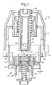
- Fig. 1 shows a coupling for interconnecting two hollow bodies, such as a collapsible or rigid container and a tube, and allow fluid flow there between.
- the coupling comprises a first interconnectable member 10 comprising a housing 11 and, fitted within the housing 11, a hollow post 12 of which the interior communicates with the interior of the body to which the first member is attached.
- the post 12 has a closed end 13 and four openings 14 situated behind the closed end 13.
- the post 12 is surrounded by a seal sleeve 15 which is biased by a spring 16 into a position covering the openings 14 to prevent outflow from the interior of the post 12.
- the housing 11 is fitted with a cylindrical key 17, which is provided with spiral grooves 18 on its inner side and which preferably has an inner diameter within the range from 40 to 80 mm.
- Fig. 1 further shows a second interconnectable member 20 comprising a cap 21 having a cylindrical portion or wall 22 having an outer diameter smaller than the inner diameter of the key 17 and provided with two projections 23 on its outer side.
- the projections 23 are each located at a distance from the end of the cylindrical wall 22, so that the second member 20 must be inserted into the first member over a certain length "L", for example 13 mm, before the projections 23 arrive at the beginning of the corresponding grooves 18.
- Said length "L” should preferably be in excess of 10 mm (and, for practical reasons, preferably be smaller than 25 mm).
- grooves can be provided on the outer side of the cap 21.
- projections should be provided on the inner side of the cylindrical wall of the first member located at a certain distance from the end the said wall.
- the pitch of the grooves 18 preferably exceeds the inner radius of the key 17, so as to enable connection through limited rotation of the members 10, 20.
- a basket 24 is fitted in the under side of the cap 21, which basket 24 comprises a piston 25 provided with a piston head 26.
- the piston 25, 26 is biased by means of a spring 27 into a position closing an aperture 28 in the cap 21.
- the cap 21 comprises an annular raised edge 29, which has an inner diameter substantially equal to or slightly larger than the outer diameter of the seal sleeve 15 of the first member 10.
- a rubber ring 30 is fitted inside the annular edge 29, which ring 30 has a height smaller than the height of the annular edge 29 and has an inner diameter substantially equal to or slightly larger than the outer diameter of the post 12 of the first member 10.
- the ring 30 is provided with three annular ridges 31 on its inner surface, which will improve the close fit and, upon disconnection of the members 10, 20, will wipe the post 12 as it is drawn through the ring 30.
- the piston head 26 is made of a flexible material, and its surface is convex. If the surface of the closed end 13 of the post 12 is concave, with the radius of the piston head 26 being selected smaller than the radius of the closed end 13 of the post 12, any liquid present between the said surfaces is displaced during connection of members 10, 20 and liquid build-up between the said surface, which results in spillage during disconnection of the members 10, 20, is avoided.
- Fig. 1 shows the first stage of establishing the interconnection between the members 10 and 20.
- the tolerance "T" between the wall 22 and the key 17 i.e., half the difference between the inner diameter of the key 17 and the outer diameter of the wall 22
- the coupling may comprise two or more of the said projections and corresponding grooves, with at least two of the projections being different in shape and/or width and the corresponding grooves being matched accordingly.
- a mix-up of interconnectable members can be avoided by using different combinations of such different projections.
- the advantages of employing couplings with the ratio "T/L" in the forementioned range are all the more noticeable when the number of (different) projections in a particular coupling increases.
- the members 10 and 20 are, as shown in figures 2 and 3, rotated with respect to one another, thus establishing contact between the seal sleeve 15 and the rubber ring 30.
- the post 12 starts moving relative to the biased seal sleeve 15 because the latter is halted by the said ring 30.
- the post 12 is now inserted in and surrounded by the ring 30 and the ring 30 is (slightly) compressed in the axial direction by the seal sleeve 15 as result of which the ring 30 begins to expand (slightly) in the radial direction towards the post 12.
- the friction between the post 12 and the ring 30 is still relatively low, so as to allow easy rotation of the members.
- Figure 3 shows the final stage of establishing the connection.
- the members 10, 20 have been rotated over a total angle of approximately 45° and the ring 30 is compressed to such an extend that it completely seals off the post 12.
- the shape of the inner side of the ring 30 is now adapted to the shape of the post 12 and a close fit is obtained, even if the post 12 has been subjected to considerable wear after several years of use.
- One of the members may be provided with a cam 32, whereas the other member is provided with a thin plastic finger 33.
- the cam 32 and finger 33 are positioned such that, during rotation of the members 10, 20, the cam 32 passes the finger 33, causing the finger 33 to bend and, substantially simultaneously to establishing an adequate connection, snap back into its original position so as to produce an audible sound, e.g. a distinct click, and warn the operator that no further rotation is required.
- a finger can be provided in the key 17 at the end of at least one of the grooves 18.
- the projection or projections 23 will pass the finger or fingers.
- the finger or fingers are caused to bend and snap back in manner similar to that described above or, in case of a rigid finger, the projection is halted until it slips abruptly and collides with a stop positioned behind (as seen in the direction of movement of the projection) the finger.
- one of the two members includes or is connected to a chamber having means for detecting the presence of liquid in the chamber.
- this will be the member which is connected to a tube.
- the chamber may contain a Reed-element or spaced apart electrodes so that the liquid when present provides a conductive path between the electrodes.
- the chamber may have a valve which is biased closed but arranged open to admit air to the chamber in the event that a pre-determined sub-atmospheric pressure is created within the chamber, for example if a pump drawing from the chamber is continuing to run when the supplying container is empty.
Landscapes
- Engineering & Computer Science (AREA)
- General Engineering & Computer Science (AREA)
- Mechanical Engineering (AREA)
- Quick-Acting Or Multi-Walled Pipe Joints (AREA)
- Mutual Connection Of Rods And Tubes (AREA)
- Loading And Unloading Of Fuel Tanks Or Ships (AREA)
- Mechanical Operated Clutches (AREA)
- Saccharide Compounds (AREA)
- Standing Axle, Rod, Or Tube Structures Coupled By Welding, Adhesion, Or Deposition (AREA)
- Connection Of Plates (AREA)
Priority Applications (1)
| Application Number | Priority Date | Filing Date | Title |
|---|---|---|---|
| EP00940284A EP1185480B1 (en) | 1999-06-10 | 2000-05-26 | Coupling |
Applications Claiming Priority (4)
| Application Number | Priority Date | Filing Date | Title |
|---|---|---|---|
| EP99201850 | 1999-06-10 | ||
| EP99201850 | 1999-06-10 | ||
| EP00940284A EP1185480B1 (en) | 1999-06-10 | 2000-05-26 | Coupling |
| PCT/EP2000/004920 WO2000076907A1 (en) | 1999-06-10 | 2000-05-26 | Coupling |
Publications (2)
| Publication Number | Publication Date |
|---|---|
| EP1185480A1 EP1185480A1 (en) | 2002-03-13 |
| EP1185480B1 true EP1185480B1 (en) | 2003-11-26 |
Family
ID=8240297
Family Applications (1)
| Application Number | Title | Priority Date | Filing Date |
|---|---|---|---|
| EP00940284A Expired - Lifetime EP1185480B1 (en) | 1999-06-10 | 2000-05-26 | Coupling |
Country Status (11)
| Country | Link |
|---|---|
| EP (1) | EP1185480B1 (enExample) |
| JP (1) | JP4663938B2 (enExample) |
| AT (1) | ATE255063T1 (enExample) |
| AU (1) | AU754567B2 (enExample) |
| BR (1) | BR0011388A (enExample) |
| CA (1) | CA2373995A1 (enExample) |
| DE (1) | DE60006809T2 (enExample) |
| ES (1) | ES2206250T3 (enExample) |
| TR (1) | TR200103555T2 (enExample) |
| WO (1) | WO2000076907A1 (enExample) |
| ZA (1) | ZA200109430B (enExample) |
Families Citing this family (11)
| Publication number | Priority date | Publication date | Assignee | Title |
|---|---|---|---|---|
| CN1956914B (zh) * | 2004-05-19 | 2012-02-22 | 皇家飞利浦电子股份有限公司 | 用于带有内袋的容器的阀组件 |
| WO2005113414A1 (en) * | 2004-05-19 | 2005-12-01 | Koninklijke Philips Electronics N.V. | Valve assembly with positioning means for a keg with an inner bag |
| EP1760385B1 (en) * | 2004-06-01 | 2015-05-06 | Surpass Industry Co., Ltd. | Connector to be attached to liquid tank and liquid tank provided with the connector |
| SE0402581L (sv) * | 2004-10-22 | 2006-04-23 | Nhi Consulting Ab | Kopplingsanordning för överföring av ett flöde |
| EP2220418A1 (en) * | 2007-10-30 | 2010-08-25 | Danfoss A/S | Non-drip coupling device for transferring a fluid |
| NO334876B1 (no) * | 2011-05-27 | 2014-06-23 | Aker Subsea As | Hot stab og tilhørende mottaks-sammenstilling |
| RU2624357C2 (ru) | 2011-11-16 | 2017-07-03 | Конватек Текнолоджиз Инк. | Аппарат предотвращения перекачки удерживающего баллончика в медицинских катетерах и устройствах поддержания положительного давления в дыхательных путях |
| BR112016002257A2 (pt) | 2013-08-01 | 2017-12-12 | Convatec Technologies Inc | conector de saco de fechamento automático |
| WO2016051759A1 (ja) * | 2014-09-29 | 2016-04-07 | テルモ株式会社 | メスコネクタ、オスコネクタ及びコネクタ接続体 |
| CA2992975C (en) | 2015-05-18 | 2023-09-05 | Convatec Technologies Inc. | Spring-loaded bag connector |
| CA3003289C (en) | 2015-10-29 | 2024-05-07 | Convatec Technologies Inc. | Valve system for inflatable devices |
Family Cites Families (7)
| Publication number | Priority date | Publication date | Assignee | Title |
|---|---|---|---|---|
| US2509444A (en) * | 1947-06-17 | 1950-05-30 | M B G Corp | Fluid coupling |
| GB8628442D0 (en) * | 1986-11-27 | 1986-12-31 | Unilever Plc | Coupling |
| JPH0324957Y2 (enExample) * | 1988-09-14 | 1991-05-30 | ||
| JPH0288090U (enExample) * | 1988-12-26 | 1990-07-12 | ||
| US4949745A (en) * | 1988-12-27 | 1990-08-21 | Air-Lock, Incorporated | Clean air connector |
| US5211197A (en) * | 1992-01-03 | 1993-05-18 | Aeroquip Corporation | Quick disconnect liquid line coupling with volumertric expansion couping element |
| CA2144494C (en) * | 1994-03-31 | 2000-02-15 | Clark E. Harris | Valve assemblage and method of use |
-
2000
- 2000-05-26 WO PCT/EP2000/004920 patent/WO2000076907A1/en not_active Ceased
- 2000-05-26 CA CA002373995A patent/CA2373995A1/en not_active Abandoned
- 2000-05-26 EP EP00940284A patent/EP1185480B1/en not_active Expired - Lifetime
- 2000-05-26 JP JP2001503379A patent/JP4663938B2/ja not_active Expired - Fee Related
- 2000-05-26 AU AU55269/00A patent/AU754567B2/en not_active Ceased
- 2000-05-26 BR BR0011388-3A patent/BR0011388A/pt not_active IP Right Cessation
- 2000-05-26 TR TR2001/03555T patent/TR200103555T2/xx unknown
- 2000-05-26 AT AT00940284T patent/ATE255063T1/de not_active IP Right Cessation
- 2000-05-26 DE DE60006809T patent/DE60006809T2/de not_active Expired - Lifetime
- 2000-05-26 ES ES00940284T patent/ES2206250T3/es not_active Expired - Lifetime
-
2001
- 2001-11-15 ZA ZA200109430A patent/ZA200109430B/xx unknown
Also Published As
| Publication number | Publication date |
|---|---|
| BR0011388A (pt) | 2002-03-05 |
| DE60006809T2 (de) | 2004-05-19 |
| ATE255063T1 (de) | 2003-12-15 |
| CA2373995A1 (en) | 2000-12-21 |
| EP1185480A1 (en) | 2002-03-13 |
| ZA200109430B (en) | 2003-01-29 |
| TR200103555T2 (tr) | 2002-05-21 |
| JP4663938B2 (ja) | 2011-04-06 |
| ES2206250T3 (es) | 2004-05-16 |
| WO2000076907A1 (en) | 2000-12-21 |
| JP2003502588A (ja) | 2003-01-21 |
| AU5526900A (en) | 2001-01-02 |
| AU754567B2 (en) | 2002-11-21 |
| DE60006809D1 (de) | 2004-01-08 |
Similar Documents
| Publication | Publication Date | Title |
|---|---|---|
| EP1185479B1 (en) | Coupling | |
| EP1192101B1 (en) | Coupling with valves | |
| CA2520324C (en) | Double slider valve fitment | |
| US6644367B1 (en) | Connector assembly for fluid flow with rotary motion for connection and disconnection | |
| AU689554B2 (en) | Back-flow preventing bag valve for bag-in-box container | |
| EP1185480B1 (en) | Coupling | |
| CA2121261A1 (en) | Fluid dispense system | |
| EP3261979B1 (en) | Hollow body coupling device | |
| EP0270302B1 (en) | Coupling | |
| US20160185588A1 (en) | Coupling Device | |
| CA2412324C (en) | Coupling | |
| AU2003200573B2 (en) | Piston Suitable for Use with a Coupling | |
| EP1206386A1 (en) | Connector assembly for fluid flow with rotary motion for connection and disconnection | |
| JP2021187442A (ja) | 連結システム |
Legal Events
| Date | Code | Title | Description |
|---|---|---|---|
| PUAI | Public reference made under article 153(3) epc to a published international application that has entered the european phase |
Free format text: ORIGINAL CODE: 0009012 |
|
| 17P | Request for examination filed |
Effective date: 20011112 |
|
| AK | Designated contracting states |
Kind code of ref document: A1 Designated state(s): AT BE CH CY DE DK ES FI FR GB GR IE IT LI LU MC NL PT SE |
|
| AX | Request for extension of the european patent |
Free format text: AL;LT;LV;MK;RO;SI |
|
| RAP1 | Party data changed (applicant data changed or rights of an application transferred) |
Owner name: JOHNSONDIVERSEY, INC. |
|
| 17Q | First examination report despatched |
Effective date: 20030115 |
|
| GRAH | Despatch of communication of intention to grant a patent |
Free format text: ORIGINAL CODE: EPIDOS IGRA |
|
| GRAS | Grant fee paid |
Free format text: ORIGINAL CODE: EPIDOSNIGR3 |
|
| GRAA | (expected) grant |
Free format text: ORIGINAL CODE: 0009210 |
|
| AK | Designated contracting states |
Kind code of ref document: B1 Designated state(s): AT BE CH CY DE DK ES FI FR GB GR IE IT LI LU MC NL PT SE |
|
| PG25 | Lapsed in a contracting state [announced via postgrant information from national office to epo] |
Ref country code: BE Free format text: LAPSE BECAUSE OF FAILURE TO SUBMIT A TRANSLATION OF THE DESCRIPTION OR TO PAY THE FEE WITHIN THE PRESCRIBED TIME-LIMIT Effective date: 20031126 Ref country code: FI Free format text: LAPSE BECAUSE OF FAILURE TO SUBMIT A TRANSLATION OF THE DESCRIPTION OR TO PAY THE FEE WITHIN THE PRESCRIBED TIME-LIMIT Effective date: 20031126 Ref country code: AT Free format text: LAPSE BECAUSE OF FAILURE TO SUBMIT A TRANSLATION OF THE DESCRIPTION OR TO PAY THE FEE WITHIN THE PRESCRIBED TIME-LIMIT Effective date: 20031126 Ref country code: CY Free format text: LAPSE BECAUSE OF FAILURE TO SUBMIT A TRANSLATION OF THE DESCRIPTION OR TO PAY THE FEE WITHIN THE PRESCRIBED TIME-LIMIT Effective date: 20031126 |
|
| REG | Reference to a national code |
Ref country code: GB Ref legal event code: FG4D |
|
| REG | Reference to a national code |
Ref country code: CH Ref legal event code: EP |
|
| REF | Corresponds to: |
Ref document number: 60006809 Country of ref document: DE Date of ref document: 20040108 Kind code of ref document: P |
|
| REG | Reference to a national code |
Ref country code: IE Ref legal event code: FG4D |
|
| PG25 | Lapsed in a contracting state [announced via postgrant information from national office to epo] |
Ref country code: GR Free format text: LAPSE BECAUSE OF FAILURE TO SUBMIT A TRANSLATION OF THE DESCRIPTION OR TO PAY THE FEE WITHIN THE PRESCRIBED TIME-LIMIT Effective date: 20040226 Ref country code: DK Free format text: LAPSE BECAUSE OF FAILURE TO SUBMIT A TRANSLATION OF THE DESCRIPTION OR TO PAY THE FEE WITHIN THE PRESCRIBED TIME-LIMIT Effective date: 20040226 |
|
| REG | Reference to a national code |
Ref country code: SE Ref legal event code: TRGR |
|
| REG | Reference to a national code |
Ref country code: ES Ref legal event code: FG2A Ref document number: 2206250 Country of ref document: ES Kind code of ref document: T3 |
|
| LTIE | Lt: invalidation of european patent or patent extension |
Effective date: 20031126 |
|
| PG25 | Lapsed in a contracting state [announced via postgrant information from national office to epo] |
Ref country code: LU Free format text: LAPSE BECAUSE OF NON-PAYMENT OF DUE FEES Effective date: 20040526 Ref country code: IE Free format text: LAPSE BECAUSE OF NON-PAYMENT OF DUE FEES Effective date: 20040526 |
|
| PG25 | Lapsed in a contracting state [announced via postgrant information from national office to epo] |
Ref country code: MC Free format text: LAPSE BECAUSE OF NON-PAYMENT OF DUE FEES Effective date: 20040531 |
|
| ET | Fr: translation filed | ||
| PLBE | No opposition filed within time limit |
Free format text: ORIGINAL CODE: 0009261 |
|
| STAA | Information on the status of an ep patent application or granted ep patent |
Free format text: STATUS: NO OPPOSITION FILED WITHIN TIME LIMIT |
|
| 26N | No opposition filed |
Effective date: 20040827 |
|
| REG | Reference to a national code |
Ref country code: IE Ref legal event code: MM4A |
|
| REG | Reference to a national code |
Ref country code: CH Ref legal event code: PFA Owner name: JOHNSONDIVERSEY, INC. Free format text: JOHNSONDIVERSEY, INC.#8310 16TH STREET#STURTEVANT, WISCONSIN 53177-0902 (US) -TRANSFER TO- JOHNSONDIVERSEY, INC.#8310 16TH STREET#STURTEVANT, WISCONSIN 53177-0902 (US) |
|
| PG25 | Lapsed in a contracting state [announced via postgrant information from national office to epo] |
Ref country code: PT Free format text: LAPSE BECAUSE OF NON-PAYMENT OF DUE FEES Effective date: 20040426 |
|
| PGFP | Annual fee paid to national office [announced via postgrant information from national office to epo] |
Ref country code: IT Payment date: 20090527 Year of fee payment: 10 Ref country code: SE Payment date: 20090528 Year of fee payment: 10 |
|
| REG | Reference to a national code |
Ref country code: CH Ref legal event code: PFA Owner name: DIVERSEY, INC. Free format text: JOHNSONDIVERSEY, INC.#8310 16TH STREET#STURTEVANT, WISCONSIN 53177-0902 (US) -TRANSFER TO- DIVERSEY, INC.#8310 16TH STREET - M/S 509#STURTEVANT, WI 53177-0902 (US) |
|
| REG | Reference to a national code |
Ref country code: NL Ref legal event code: TD Effective date: 20101013 |
|
| EUG | Se: european patent has lapsed | ||
| PG25 | Lapsed in a contracting state [announced via postgrant information from national office to epo] |
Ref country code: SE Free format text: LAPSE BECAUSE OF NON-PAYMENT OF DUE FEES Effective date: 20100527 Ref country code: IT Free format text: LAPSE BECAUSE OF NON-PAYMENT OF DUE FEES Effective date: 20100526 |
|
| REG | Reference to a national code |
Ref country code: FR Ref legal event code: CD |
|
| REG | Reference to a national code |
Ref country code: ES Ref legal event code: PC2A Owner name: DIVERSEY, INC. Effective date: 20110429 |
|
| REG | Reference to a national code |
Ref country code: NL Ref legal event code: PLEX Effective date: 20120724 |
|
| REG | Reference to a national code |
Ref country code: FR Ref legal event code: PLFP Year of fee payment: 17 |
|
| REG | Reference to a national code |
Ref country code: FR Ref legal event code: PLFP Year of fee payment: 18 |
|
| REG | Reference to a national code |
Ref country code: FR Ref legal event code: PLFP Year of fee payment: 19 |
|
| PGFP | Annual fee paid to national office [announced via postgrant information from national office to epo] |
Ref country code: NL Payment date: 20190526 Year of fee payment: 20 |
|
| PGFP | Annual fee paid to national office [announced via postgrant information from national office to epo] |
Ref country code: DE Payment date: 20190530 Year of fee payment: 20 Ref country code: ES Payment date: 20190603 Year of fee payment: 20 |
|
| PGFP | Annual fee paid to national office [announced via postgrant information from national office to epo] |
Ref country code: FR Payment date: 20190527 Year of fee payment: 20 |
|
| PGFP | Annual fee paid to national office [announced via postgrant information from national office to epo] |
Ref country code: CH Payment date: 20190604 Year of fee payment: 20 |
|
| PGFP | Annual fee paid to national office [announced via postgrant information from national office to epo] |
Ref country code: GB Payment date: 20190528 Year of fee payment: 20 |
|
| REG | Reference to a national code |
Ref country code: DE Ref legal event code: R071 Ref document number: 60006809 Country of ref document: DE |
|
| REG | Reference to a national code |
Ref country code: NL Ref legal event code: MK Effective date: 20200525 |
|
| REG | Reference to a national code |
Ref country code: CH Ref legal event code: PL |
|
| REG | Reference to a national code |
Ref country code: GB Ref legal event code: PE20 Expiry date: 20200525 |
|
| PG25 | Lapsed in a contracting state [announced via postgrant information from national office to epo] |
Ref country code: GB Free format text: LAPSE BECAUSE OF EXPIRATION OF PROTECTION Effective date: 20200525 |
|
| REG | Reference to a national code |
Ref country code: ES Ref legal event code: FD2A Effective date: 20200902 |
|
| PG25 | Lapsed in a contracting state [announced via postgrant information from national office to epo] |
Ref country code: ES Free format text: LAPSE BECAUSE OF EXPIRATION OF PROTECTION Effective date: 20200527 |