EP1185141A2 - Flextensional transducer and method for fabrication of a flextensional transducer - Google Patents
Flextensional transducer and method for fabrication of a flextensional transducer Download PDFInfo
- Publication number
- EP1185141A2 EP1185141A2 EP01307456A EP01307456A EP1185141A2 EP 1185141 A2 EP1185141 A2 EP 1185141A2 EP 01307456 A EP01307456 A EP 01307456A EP 01307456 A EP01307456 A EP 01307456A EP 1185141 A2 EP1185141 A2 EP 1185141A2
- Authority
- EP
- European Patent Office
- Prior art keywords
- nozzle
- transducer
- actuator body
- aperture
- transducer membrane
- Prior art date
- Legal status (The legal status is an assumption and is not a legal conclusion. Google has not performed a legal analysis and makes no representation as to the accuracy of the status listed.)
- Withdrawn
Links
- 238000004519 manufacturing process Methods 0.000 title claims abstract description 19
- 238000000034 method Methods 0.000 title claims description 34
- 239000012528 membrane Substances 0.000 claims abstract description 74
- 239000000463 material Substances 0.000 claims abstract description 53
- 230000009969 flowable effect Effects 0.000 claims abstract description 45
- 239000002184 metal Substances 0.000 claims abstract description 25
- 229910052751 metal Inorganic materials 0.000 claims abstract description 25
- 238000004021 metal welding Methods 0.000 claims abstract description 22
- 239000000853 adhesive Substances 0.000 claims description 22
- 230000001070 adhesive effect Effects 0.000 claims description 22
- 238000007641 inkjet printing Methods 0.000 claims description 11
- 230000008878 coupling Effects 0.000 claims description 8
- 238000010168 coupling process Methods 0.000 claims description 8
- 238000005859 coupling reaction Methods 0.000 claims description 8
- 239000007769 metal material Substances 0.000 claims description 6
- 238000000151 deposition Methods 0.000 claims description 3
- 210000004907 gland Anatomy 0.000 abstract description 4
- 239000010410 layer Substances 0.000 description 23
- 238000005516 engineering process Methods 0.000 description 17
- 239000004593 Epoxy Substances 0.000 description 14
- 125000003700 epoxy group Chemical group 0.000 description 11
- 229920000647 polyepoxide Polymers 0.000 description 11
- 238000005553 drilling Methods 0.000 description 8
- 238000000608 laser ablation Methods 0.000 description 7
- 238000010304 firing Methods 0.000 description 6
- 239000003292 glue Substances 0.000 description 6
- 230000008569 process Effects 0.000 description 6
- 239000000126 substance Substances 0.000 description 6
- 239000000203 mixture Substances 0.000 description 5
- PCHJSUWPFVWCPO-UHFFFAOYSA-N gold Chemical compound [Au] PCHJSUWPFVWCPO-UHFFFAOYSA-N 0.000 description 4
- 239000010931 gold Substances 0.000 description 4
- 229910052737 gold Inorganic materials 0.000 description 4
- 238000010438 heat treatment Methods 0.000 description 4
- 229910052709 silver Inorganic materials 0.000 description 4
- 239000004332 silver Substances 0.000 description 4
- RYGMFSIKBFXOCR-UHFFFAOYSA-N Copper Chemical compound [Cu] RYGMFSIKBFXOCR-UHFFFAOYSA-N 0.000 description 3
- BQCADISMDOOEFD-UHFFFAOYSA-N Silver Chemical compound [Ag] BQCADISMDOOEFD-UHFFFAOYSA-N 0.000 description 3
- 239000012790 adhesive layer Substances 0.000 description 3
- 239000003518 caustics Substances 0.000 description 3
- 239000000919 ceramic Substances 0.000 description 3
- 229910052802 copper Inorganic materials 0.000 description 3
- 239000010949 copper Substances 0.000 description 3
- 230000007797 corrosion Effects 0.000 description 3
- 238000005260 corrosion Methods 0.000 description 3
- 239000012530 fluid Substances 0.000 description 3
- 229910052734 helium Inorganic materials 0.000 description 3
- 239000001307 helium Substances 0.000 description 3
- SWQJXJOGLNCZEY-UHFFFAOYSA-N helium atom Chemical compound [He] SWQJXJOGLNCZEY-UHFFFAOYSA-N 0.000 description 3
- 239000007787 solid Substances 0.000 description 3
- 229910001369 Brass Inorganic materials 0.000 description 2
- 239000010951 brass Substances 0.000 description 2
- 238000004891 communication Methods 0.000 description 2
- 230000008602 contraction Effects 0.000 description 2
- 238000010586 diagram Methods 0.000 description 2
- FPAFDBFIGPHWGO-UHFFFAOYSA-N dioxosilane;oxomagnesium;hydrate Chemical compound O.[Mg]=O.[Mg]=O.[Mg]=O.O=[Si]=O.O=[Si]=O.O=[Si]=O.O=[Si]=O FPAFDBFIGPHWGO-UHFFFAOYSA-N 0.000 description 2
- 230000000694 effects Effects 0.000 description 2
- 230000003628 erosive effect Effects 0.000 description 2
- 150000002739 metals Chemical class 0.000 description 2
- 239000002245 particle Substances 0.000 description 2
- 238000007639 printing Methods 0.000 description 2
- 230000004044 response Effects 0.000 description 2
- 238000003466 welding Methods 0.000 description 2
- 230000001133 acceleration Effects 0.000 description 1
- 230000003213 activating effect Effects 0.000 description 1
- 230000004913 activation Effects 0.000 description 1
- 230000006978 adaptation Effects 0.000 description 1
- 230000015572 biosynthetic process Effects 0.000 description 1
- 229910010293 ceramic material Inorganic materials 0.000 description 1
- 239000004020 conductor Substances 0.000 description 1
- 238000004320 controlled atmosphere Methods 0.000 description 1
- 230000008021 deposition Effects 0.000 description 1
- 238000009792 diffusion process Methods 0.000 description 1
- 230000007613 environmental effect Effects 0.000 description 1
- 239000012535 impurity Substances 0.000 description 1
- 230000002401 inhibitory effect Effects 0.000 description 1
- 239000007788 liquid Substances 0.000 description 1
- 239000011344 liquid material Substances 0.000 description 1
- 238000003754 machining Methods 0.000 description 1
- 230000007257 malfunction Effects 0.000 description 1
- 230000003287 optical effect Effects 0.000 description 1
- 238000009877 rendering Methods 0.000 description 1
- 230000000630 rising effect Effects 0.000 description 1
- 229910001220 stainless steel Inorganic materials 0.000 description 1
- 239000010935 stainless steel Substances 0.000 description 1
Images

Classifications
-
- B—PERFORMING OPERATIONS; TRANSPORTING
- B41—PRINTING; LINING MACHINES; TYPEWRITERS; STAMPS
- B41J—TYPEWRITERS; SELECTIVE PRINTING MECHANISMS, i.e. MECHANISMS PRINTING OTHERWISE THAN FROM A FORME; CORRECTION OF TYPOGRAPHICAL ERRORS
- B41J2/00—Typewriters or selective printing mechanisms characterised by the printing or marking process for which they are designed
- B41J2/005—Typewriters or selective printing mechanisms characterised by the printing or marking process for which they are designed characterised by bringing liquid or particles selectively into contact with a printing material
- B41J2/01—Ink jet
- B41J2/135—Nozzles
- B41J2/16—Production of nozzles
- B41J2/1621—Manufacturing processes
- B41J2/1623—Manufacturing processes bonding and adhesion
-
- B—PERFORMING OPERATIONS; TRANSPORTING
- B41—PRINTING; LINING MACHINES; TYPEWRITERS; STAMPS
- B41J—TYPEWRITERS; SELECTIVE PRINTING MECHANISMS, i.e. MECHANISMS PRINTING OTHERWISE THAN FROM A FORME; CORRECTION OF TYPOGRAPHICAL ERRORS
- B41J2/00—Typewriters or selective printing mechanisms characterised by the printing or marking process for which they are designed
- B41J2/005—Typewriters or selective printing mechanisms characterised by the printing or marking process for which they are designed characterised by bringing liquid or particles selectively into contact with a printing material
- B41J2/01—Ink jet
- B41J2/135—Nozzles
- B41J2/16—Production of nozzles
- B41J2/1607—Production of print heads with piezoelectric elements
- B41J2/161—Production of print heads with piezoelectric elements of film type, deformed by bending and disposed on a diaphragm
-
- B—PERFORMING OPERATIONS; TRANSPORTING
- B41—PRINTING; LINING MACHINES; TYPEWRITERS; STAMPS
- B41J—TYPEWRITERS; SELECTIVE PRINTING MECHANISMS, i.e. MECHANISMS PRINTING OTHERWISE THAN FROM A FORME; CORRECTION OF TYPOGRAPHICAL ERRORS
- B41J2/00—Typewriters or selective printing mechanisms characterised by the printing or marking process for which they are designed
- B41J2/005—Typewriters or selective printing mechanisms characterised by the printing or marking process for which they are designed characterised by bringing liquid or particles selectively into contact with a printing material
- B41J2/01—Ink jet
- B41J2/135—Nozzles
- B41J2/16—Production of nozzles
- B41J2/1621—Manufacturing processes
- B41J2/1632—Manufacturing processes machining
- B41J2/1634—Manufacturing processes machining laser machining
Definitions
- the present invention relates generally to drop-on-demand technology capable of ejecting droplets of a flowable material, and more specifically to a flextensional transducer utilizing an ultrasonic metal welding technique to bond components together such that no adhesive or epoxy materials are necessary.
- Inkjet printing is a technology that uses small drops of a flowable material, such as an ink droplet, to form an image on a medium.
- a flowable material such as an ink droplet
- Continuous flow technology uses electrostatic acceleration and deflection to select ink drops from a continuous flow of ink to form an image.
- Drop-on-demand technology can be divided into two sub-categories, thermal inkjet technology and piezoelectric inkjet technology.
- Thermal inkjet technology uses heat energy to vaporize a thin layer or bubble of ink which expels unvaporized ink above a resistive element and fires the ink through a nozzle.
- the physical components needed to implement thermal inkjet technology are embedded within an inkjet print cartridge.
- piezoelectric inkjet technology includes an electro-mechanical means to eject a flowable material, such as an ink droplet. More specifically, an electrical signal is supplied to an orifice plate of a nozzle which forces a portion of the orifice plate to flex or contract into the nozzle, thereby causing an ejection of an ink droplet from the nozzle.
- Conventional piezoelectric inkjet technology utilizes an adhesive bond, such as a glue or an epoxy, to bond several components of a flextensional transducer relating to fire of an ink droplet.
- an adhesive bond such as a glue or an epoxy
- a piezoelectric body or ring is bonded to a transducer membrane, which is in turn bonded to a nozzle or an orifice plate of a nozzle.
- An adhesive or epoxy bond forms each of these connections.
- the piezoelectric body, transducer membrane, and nozzle each include an aperture through which the ink droplets are fired. These apertures are formed by a drilling process.
- Ink droplets used in conventional inkjet printers are made up of various chemicals, some of which are extremely caustic. These caustic chemicals have a tendency to attack the adhesive bond layers of conventional inkjet printers such that the adhesive bond layers dissolve and a mechanical malfunction occurs. The erosion of the adhesive layers prevents the inkjet printer from properly operating.
- the present invention is a flextensional transducer apparatus and method of fabricating a flextensional transducer apparatus capable of ejecting a flowable material, such as a droplet of ink.
- the present invention includes ultrasonically metal welding various components of the flextensional transducer to securely interconnect the components of the flextensional transducer. Thus, no adhesives, glues, or epoxies are used.
- the aperture in one or more of the layers are laser ablated prior to any ultrasonic metal welding.
- a layer of an ultrasonic weldable metal material such as a layer of gold, silver, or brass, is deposited onto one or more surfaces of the actuator body, the transducer membrane, or the nozzle, prior to the ultrasonic metal welding of the components to ensure a proper bond.
- the method of fabricating the flextensional transducer further includes electrically coupling a first electrical lead to the actuator body while electrically coupling a second electrical lead to the nozzle. Electrical circuitry is electrically coupled to the first and second electrical leads and is capable of providing an electrical signal to the flextensional transducer.
- the actuator body and the transducer membrane flexes or contracts towards the nozzle, thereby ejecting the flowable material.
- the method of fabricating the flextensional transducer further includes fluidly coupling a reservoir of the flowable material to the nozzle.
- the flextensional transducer apparatus of the present invention is capable of ejecting a flowable material.
- the flextensional transducer apparatus includes an actuator body having an outer diameter and an aperture.
- a transducer membrane is associated with the actuator body.
- the transducer membrane has an outer diameter and an aperture.
- a nozzle is associated with the transducer membrane. The nozzle is capable of housing a portion of the flowable material and includes a surface adjacent to the transducer membrane having an aperture.
- the outer diameter of the actuator body is smaller than the aperture in the surface of the nozzle adjacent to the transducer membrane.
- the actuator body is a piezo-ceramic ring.
- an ultrasonic weldable metal material layer is fabricated onto one or more surfaces of the actuator body, the transducer membrane, or the nozzle.
- the flextensional transducer apparatus further includes a first electrical lead electrically coupled to the actuator body and a second electrical lead electrically coupled to the nozzle. Electrical circuitry is electrically coupled to the first and second electrical leads capable of providing an electrical signal to the flextensional transducer apparatus causing the actuator body and the transducer membrane flex or contract towards the nozzle.
- the flextensional transducer apparatus includes a flowable material reservoir capable of housing the flowable material in fluid communication with the nozzle.
- the present flextensional transducer provides several advantages over conventional flextensional transducers used in piezoelectric inkjet technology.
- First, the present invention produces a permanent bond without a significant heating. Heating can weaken various layers of a conventional transducer.
- Second, the present invention provides interconnection points between components which do not become brittle.
- Third, the present invention provides interconnection of components which are corrosion resistant.
- Fourth, the present invention provides good electric connectivity between components.
- Fifth, the present invention requires no consumable materials, such as adhesives or epoxies.
- the present invention requires no special environmental conditions, such as a helium atmosphere or a vacuum, in the fabrication process. Seventh, the present invention provides the laser ablation process for machine holes in one or more of the components which can be precisely controlled, as compared to traditional machining processes, such as drilling.
- the present invention includes an apparatus and method in which an ultrasonic metal welding process is utilized to bond various components of a flextensional transducer capable of ejecting a flowable material. Since no adhesives or glues are used to bond various components together, several negative attributes of conventional inkjet printing devices are minimized. For example, corrosion of adhesives leading to mechanical failure is alleviated. In addition, the manufacturing process is simplified in that no special conditions, such as a helium atmosphere or a vacuum, is required. Also, the electrical connection between various components is improved. Additionally, a permanent bond is produced with localized heating, which does not effect the robust quality of various components. In addition, no consumable materials, such as adhesives or epoxies, are required. Also, utilizing a laser ablation procedure provides a more accurate aperture in one or more of the components than a mechanical drilling procedure.
- Printhead assembly 52 receives ink from ink supply assembly 54.
- Ink supply assembly 54 includes reservoir 68 for storing a volume of ink.
- Ink supply assembly 54 and printhead assembly 52 form either a one way ink delivery system or a re-circulating ink delivery system.
- ink flows from reservoir 68 into printhead assembly 52. Some of the ink travels into chambers within flextensional transducers 64, while other portions of ink return to ink reservoir 68.
- ink supply assembly 54 and printhead assembly 52 are housed together in a pen or cartridge.
- ink supply assembly 54 is separate from printhead assembly 52 and feeds ink to printhead assembly 52 through an interface connection, such as a supply tube.
- the ink supply may be removed, replaced, and/or refilled.
- the pen may be disassembled and the interior reservoir removed. A new, filled reservoir then is placed within the pen, and the pen reassembled for reuse.
- the prior reservoir may be refilled and reinstalled in the pen or filled in place without removing from the pen (and in some embodiments, without even disassembling the pen).
- printhead assembly 52 is mounted relative to housing 60 to define a print zone 70 adjacent to flextensional transducers 64 in an area which is to receive media sheet 66. Media sheet 66 is moved into print zone 70 by media transport assembly 58.
- Mounting assembly 56 positions printhead assembly 52 relative to media transport assembly 58. For a scanning-type printhead assembly, mounting assembly 56 includes a carriage for moving printhead assembly 52 relative to a media transport path to scan printhead assembly 52 with respect to a media sheet. For a non-scanning type printhead assembly, mounting assembly 56 fixes printhead assembly 52 at a described positioned along the media transport path.
- Electronic controller 62 selects which flextensional transducer 64 are activated at a given time by activating corresponding drive signals.
- logic circuitry and drive circuitry form a portion of controller 62. In an alternative embodiment, logic circuitry and drive circuitry are located within printhead assembly 52.
- actuator body 80 is a piezo-ceramic material formed into a disc formation.
- Actuator body 80 preferably has a thickness in the range of approximately 0.5-5.0 mil, and an outer diameter in the range of approximately 0.10-0.30 inches and an inner diameter in the range of approximately 0.05 and 0.1 inches.
- Aperture 82 can be formed by standard mechanical drilling techniques known in the art, or by a laser ablation procedure. A laser ablation procedure has significantly more control and accuracy, as compared to a drilling procedure. Current laser technology is capable of producing an aperture within a piezo-ceramic ring having a thickness in the range discussed above.
- Nozzle 88 includes a hollow cylinder from a top end to a bottom end of nozzle 88, wherein aperture 90 represents the cylinder at surface 92.
- Nozzle 88 is capable of holding or storing a portion of a flowable material.
- This flowable material may be any material capable of being ejected from nozzle 88 through apertures 90, 86, and 82.
- the flowable material may be a liquid material, such as a droplet of ink.
- the flowable material may be a particle solid, such as talcum powder.
- actuator body 80, transducer membrane 84, and nozzle 88 are shown to have specific configurations, these configurations should not be interpreted as a limitation. Rather, various configurations of actuator body 80 and transducer membrane 84 may be used without deviating from the present invention. For example, an elliptical configuration can be used. Similarly, any configuration of a nozzle or gland capable of housing a flowable material within a defined space may be utilized without deviating from the present invention.
- metal composition layers 96 and 98 are associated with transducer membrane 84 and nozzle 88, respectively. While it is not shown in Figure 2, it is understood that similar metal composition layers can be associated with the bottom surface of actuator body 80 and the bottom surface of transducer membrane 84.
- actuator body 80 is bonded to transducer membrane 84.
- transducer membrane 84 is bonded to nozzle 88.
- Flextensional transducer 64 does not incorporate any adhesive bonds, such as glues or epoxies, in order to secure the various components to each other. Rather, an ultrasonic metal welding procedure is undertaken which bonds actuator body 80 to transducer membrane 84 and transducer membrane 84 to nozzle 88 in a secure manner.
- Ultrasonic metal welding is a technique in which two metal pieces or components are placed on top of each other and then are forced to move back and forth relative to each other at a frequency in the range of approximately 10-100 kilohertz, vibrating against each other until there is an atomic diffusion between the two pieces of metal, thereby creating a single interfused material. More particularly, ultrasonic welding of components is accomplished by creating high frequency vibrations from an ultrasonic welding horn which contacts a surface of the components being assembled. The vibration causes surface and intermolecular friction between the components which produces a sharp rise in temperature at the joints where the components meet. The rising temperature becomes great enough to then melt the metal causing a flow of metal between the components. After cessation of the vibration, the metal materials solidify and a weld results.
- the ultrasonic metal welding process is complete in the range of approximately 0.01-1.00 seconds. In one preferred embodiment, the process is completed in one-tenth of one second.
- the ultrasonic metal welding process used in the present invention does not require a "clean" environment.
- Conventional procedures utilizing adhesives and epoxies require an environmentally controlled atmosphere, such as a vacuum.
- ultrasonic metal welding does not require a clean atmosphere.
- the underlying requirements of an ultrasonic metal welding procedure provides a vibration process in which various oxide greases and related impurities are "scrubbed off".
- the fabrication of the flextensional transducer in accordance with the present inventions significantly reduces the manufacturing costs as compared to conventional flextensional transducers.
- the metals used in the fabrication of actuator body 80, transducer membrane 84, and nozzle 88 to be ultrasonically metal welded together are "soft" metals, such as gold, copper, silver, or any other metal having similar strength characteristics.
- actuator body 80 is a piezoelectric component.
- actuator body 80 is a ceramic component.
- the fabrication of an additional layer of a soft metal actuator body 80, transducer membrane 84, and nozzle 88, regardless of whether one or more of these layers are formed from soft or non-soft metal layers, may enhance the ultrasonic metal welding process. If an additional layer of a soft metal is added to one or more components of flextensional transducer 64, the additional layer may have a thickness in the range of approximately 1-20 microns. In one preferred embodiment, the additional layer is 5 microns thick.
- FIGs 3 and 4 illustrate the ultrasonic metal welding fabrication technique previously discussed.
- actuator body 80 is ultrasonically metal welded to transducer membrane 84.
- a layer of a soft metal such as layer 96, may or may not be necessary. It is also understood that a layer of a soft metal may also be associated with the bottom surface of actuator body 80.
- a layer of a soft metal may be fabricated onto surface 92 of nozzle 88. A similar layer may also be fabricated onto the bottom surface of transducer membrane 84.
- the outer diameter of actuator body 80 is smaller than the diameter of aperture 90 in nozzle 88.
- an electrical signal supplied to flextensional transducer 64 causes actuator body 80 to shrink, thus bonding transducer membrane 84 toward nozzle 88.
- the electrical signal causes actuator body 80 and a portion of transducer membrane 84 to flex or contract inward toward nozzle 88.
- This contraction forces a flowable material to be ejected from flextensional transducer 64, and more specifically from nozzle 88. If the outer diameter of actuator body 80 is larger than aperture 90 of nozzle 88, the proper amount of torque necessary to flex or contract actuator body 80 and transducer member 84 into nozzle 88 will be lacking and a proper ejection will not occur.
- Electrical circuitry is electrically coupled to flextensional transducer 64 via electrical leads 106 and 108.
- Electrical lead 106 is electrically connected to actuator body 80, while electrical lead 108 is electrically connected to nozzle 88.
- electrical leads 106 and 108 are bonded to actuator body 80 and nozzle 88, respectively, via the ultrasonic metal welding technique previously discussed.
- Electrical leads 106 and 108 are formed from any electrically conducting metal material, such as copper, silver, or gold.
- Electrical circuitry 100 provides an electrical signal to flextensional transducer 64 which causes actuator body 80, transducer membrane 84, and surface 92 of nozzle 88 to flex or contract inward towards nozzle 88. Electrical circuitry 100 is controlled by data 72 (shown and described with respect to Figure 1) from a host via electronic controller 62 (shown and described with respect to Figure 1).
- the present invention includes an apparatus and method in which an ultrasonic metal welding process is utilized to bond various components of a flextensional transducer capable of ejecting a flowable material. Since no adhesives or glues are used to bond various components together, several negative attributes of conventional inkjet printing devices are minimized. For example, corrosion of adhesives leading to mechanical failure is alleviated. In addition, the manufacturing process is simplified in that no special conditions, such as a helium atmosphere or a vacuum is required. Also, electrical connection between various components have improved. Additionally, a permanent bond is produced with localized heating, which does not effect the robust quality of various components. In addition, no consumable materials, such as adhesives or epoxies is required. Also, utilizing a laser ablation procedure to produce apertures in various components provides a more accurate aperture than a mechanical drilling procedure.
Landscapes
- Engineering & Computer Science (AREA)
- Manufacturing & Machinery (AREA)
- Physics & Mathematics (AREA)
- Optics & Photonics (AREA)
- Particle Formation And Scattering Control In Inkjet Printers (AREA)
Abstract
An apparatus and method of fabricating a flextensional transducer capable of
ejecting a flowable material is disclosed. The method of fabricating a flextensional
transducer capable of ejecting a flowable material includes ultrasonically metal
welding an actuator body having an outer diameter and an aperture to a transducer
membrane having an outer diameter and an aperture. The transducer membrane is
also ultrasonically metal welded to a gland or nozzle capable of housing a portion of
the flowable material. The gland or nozzle includes a surface adjacent to the
transducer membrane having an aperture. The outer diameter of the actuator body is
smaller than the aperture of the gland or nozzle.
Description
- The present invention relates generally to drop-on-demand technology capable of ejecting droplets of a flowable material, and more specifically to a flextensional transducer utilizing an ultrasonic metal welding technique to bond components together such that no adhesive or epoxy materials are necessary.
- Inkjet printing is a technology that uses small drops of a flowable material, such as an ink droplet, to form an image on a medium. Two general types of inkjet printing technology exist, continuous flow technology and drop-on-demand technology. Continuous flow technology uses electrostatic acceleration and deflection to select ink drops from a continuous flow of ink to form an image. Drop-on-demand technology can be divided into two sub-categories, thermal inkjet technology and piezoelectric inkjet technology.
- Thermal inkjet technology uses heat energy to vaporize a thin layer or bubble of ink which expels unvaporized ink above a resistive element and fires the ink through a nozzle. The physical components needed to implement thermal inkjet technology are embedded within an inkjet print cartridge. Conversely, piezoelectric inkjet technology includes an electro-mechanical means to eject a flowable material, such as an ink droplet. More specifically, an electrical signal is supplied to an orifice plate of a nozzle which forces a portion of the orifice plate to flex or contract into the nozzle, thereby causing an ejection of an ink droplet from the nozzle.
- The frequency of a thermal inkjet printing device with which an ink droplet can be "fired" is limited by the thermal characteristics of a resistive element of the thermal inkjet printing device. For example, conventional thermal inkjet printers are capable of firing at a frequency in the range of 1-100 kilohertz. Conversely, conventional piezoelectric inkjet printing devices are capable of at firing a frequency in the range of 7,500-15,000 kilohertz, or up to approximately 15 times faster than conventional thermal inkjet printing devices.
- Conventional piezoelectric inkjet technology utilizes an adhesive bond, such as a glue or an epoxy, to bond several components of a flextensional transducer relating to fire of an ink droplet. For example, a piezoelectric body or ring is bonded to a transducer membrane, which is in turn bonded to a nozzle or an orifice plate of a nozzle. An adhesive or epoxy bond forms each of these connections. The piezoelectric body, transducer membrane, and nozzle each include an aperture through which the ink droplets are fired. These apertures are formed by a drilling process.
- Ink droplets used in conventional inkjet printers are made up of various chemicals, some of which are extremely caustic. These caustic chemicals have a tendency to attack the adhesive bond layers of conventional inkjet printers such that the adhesive bond layers dissolve and a mechanical malfunction occurs. The erosion of the adhesive layers prevents the inkjet printer from properly operating.
- In addition to the erosion of adhesive layers due to the caustic chemicals discussed above, conventional inkjet technology utilizing an adhesive bond layer suffers from numerous disadvantages such as the adhesives or epoxies require time during the assembly for cure, the adhesives or epoxies require a precise deposition, the thickness of an adhesive layer varies, thereby varying the frequency response time, and the adhesives or epoxies are poor electrical conductors, thereby inhibiting the performance of the overall inkjet printer.
- There is a need for a flextensional transducer which eliminates the use of adhesives or epoxies to bond together various components of the flextensional transducer. Therefore, the materials ejected from the flextensional transducer, regardless of its chemical composition, will not attack and destroy the bond between various components, rendering the overall device inoperable.
- The present invention is a flextensional transducer apparatus and method of fabricating a flextensional transducer apparatus capable of ejecting a flowable material, such as a droplet of ink. The present invention includes ultrasonically metal welding various components of the flextensional transducer to securely interconnect the components of the flextensional transducer. Thus, no adhesives, glues, or epoxies are used.
- The method of fabricating the flextensional transducer capable of ejecting a flowable material includes ultrasonically metal welding an actuator body having an outer diameter and an aperture to a transducer membrane having an outer diameter and aperture. The transducer membrane is also ultrasonically metal welded to a nozzle capable of housing a portion of the flowable material. The nozzle includes a surface adjacent to the transducer membrane having an aperture. The flowable material can be ejected through the apertures in each of the layers onto a media.
- In one preferred embodiment, the aperture in one or more of the layers are laser ablated prior to any ultrasonic metal welding. In another preferred embodiment, a layer of an ultrasonic weldable metal material, such as a layer of gold, silver, or brass, is deposited onto one or more surfaces of the actuator body, the transducer membrane, or the nozzle, prior to the ultrasonic metal welding of the components to ensure a proper bond. In yet another preferred embodiment, the method of fabricating the flextensional transducer further includes electrically coupling a first electrical lead to the actuator body while electrically coupling a second electrical lead to the nozzle. Electrical circuitry is electrically coupled to the first and second electrical leads and is capable of providing an electrical signal to the flextensional transducer. In response to the electrical signal, the actuator body and the transducer membrane flexes or contracts towards the nozzle, thereby ejecting the flowable material. In still yet another preferred embodiment, the method of fabricating the flextensional transducer further includes fluidly coupling a reservoir of the flowable material to the nozzle.
- The flextensional transducer apparatus of the present invention is capable of ejecting a flowable material. The flextensional transducer apparatus includes an actuator body having an outer diameter and an aperture. A transducer membrane is associated with the actuator body. The transducer membrane has an outer diameter and an aperture. A nozzle is associated with the transducer membrane. The nozzle is capable of housing a portion of the flowable material and includes a surface adjacent to the transducer membrane having an aperture.
- In one preferred embodiment, the outer diameter of the actuator body is smaller than the aperture in the surface of the nozzle adjacent to the transducer membrane. In another preferred embodiment, the actuator body is a piezo-ceramic ring.
- The flextensional transducer apparatus utilizes no adhesives, such as glue or epoxies, to interface the actuator body with the transducer membrane or to interface the transducer membrane with the nozzle. Rather, an ultrasonic metal welding procedure is used.
- In yet another preferred embodiment, an ultrasonic weldable metal material layer is fabricated onto one or more surfaces of the actuator body, the transducer membrane, or the nozzle.
- In still yet another preferred embodiment, the flextensional transducer apparatus further includes a first electrical lead electrically coupled to the actuator body and a second electrical lead electrically coupled to the nozzle. Electrical circuitry is electrically coupled to the first and second electrical leads capable of providing an electrical signal to the flextensional transducer apparatus causing the actuator body and the transducer membrane flex or contract towards the nozzle. In a further preferred embodiment, the flextensional transducer apparatus includes a flowable material reservoir capable of housing the flowable material in fluid communication with the nozzle.
- The present flextensional transducer provides several advantages over conventional flextensional transducers used in piezoelectric inkjet technology. First, the present invention produces a permanent bond without a significant heating. Heating can weaken various layers of a conventional transducer. Second, the present invention provides interconnection points between components which do not become brittle. Third, the present invention provides interconnection of components which are corrosion resistant. Fourth, the present invention provides good electric connectivity between components. Fifth, the present invention requires no consumable materials, such as adhesives or epoxies. Sixth, the present invention requires no special environmental conditions, such as a helium atmosphere or a vacuum, in the fabrication process. Seventh, the present invention provides the laser ablation process for machine holes in one or more of the components which can be precisely controlled, as compared to traditional machining processes, such as drilling.
-
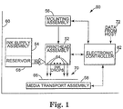
- Figure 1 is a block diagram of an inkjet printing system.
- Figure 2 is an exploded view of a portion of a flextensional transducer in accordance with the present invention.
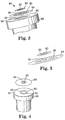
- Figure 3 is a perspective view illustrating an actuator body and a transducer membrane of a flextensional transducer in accordance with the present invention.
- Figure 4 is a perspective view of a flextensional transducer in accordance with the present invention prior to bonding the transducer member to the nozzle.
- Figure 5 is a perspective view of a flextensional transducer in a non-firing state in accordance with the present invention.
- Figure 6 is a perspective view of a flextensional transducer in a firing state in accordance with the present invention.
-
- In the following detailed description of the preferred embodiments, reference is made to the accompanying drawings which form a part hereof, and in which is shown by way of illustration specific embodiments in which the invention may be practiced. It is to be understood that other embodiments may be utilized and structural or logical changes may be made without departing from the scope of the present invention. The following detailed description, therefore, is not to be taken in a limiting sense, and the scope of the present invention is defined by the appended claims.
- The present invention includes an apparatus and method in which an ultrasonic metal welding process is utilized to bond various components of a flextensional transducer capable of ejecting a flowable material. Since no adhesives or glues are used to bond various components together, several negative attributes of conventional inkjet printing devices are minimized. For example, corrosion of adhesives leading to mechanical failure is alleviated. In addition, the manufacturing process is simplified in that no special conditions, such as a helium atmosphere or a vacuum, is required. Also, the electrical connection between various components is improved. Additionally, a permanent bond is produced with localized heating, which does not effect the robust quality of various components. In addition, no consumable materials, such as adhesives or epoxies, are required. Also, utilizing a laser ablation procedure provides a more accurate aperture in one or more of the components than a mechanical drilling procedure.
- Figure 1 is a block diagram illustrating
printing system 50 includingprinthead assembly 52,ink supply assembly 54, mountingassembly 56,media transport assembly 58,housing 60, andelectronic controller 62.Printhead assembly 52 includes one or more printheads having a plurality offlextensional transducers 64 which eject ink onto amedia sheet 66. While the figures and following text discuss an apparatus and method of fabricating a flextensional transducer capable of ejecting a droplet of ink, it is understood that any flowable material, such as a liquid or flowable particles of a solid, may be ejected. The only constraint in this regard is that the material is capable of being ejected from the transducer. -
Printhead assembly 52 receives ink fromink supply assembly 54.Ink supply assembly 54 includesreservoir 68 for storing a volume of ink.Ink supply assembly 54 andprinthead assembly 52 form either a one way ink delivery system or a re-circulating ink delivery system. For the re-circulating ink delivery system, ink flows fromreservoir 68 intoprinthead assembly 52. Some of the ink travels into chambers withinflextensional transducers 64, while other portions of ink return toink reservoir 68. - In some embodiments,
ink supply assembly 54 andprinthead assembly 52 are housed together in a pen or cartridge. In other embodiments,ink supply assembly 54 is separate fromprinthead assembly 52 and feeds ink toprinthead assembly 52 through an interface connection, such as a supply tube. For either approach, the ink supply may be removed, replaced, and/or refilled. For example, in an inkjet pen having an internal reservoir, the pen may be disassembled and the interior reservoir removed. A new, filled reservoir then is placed within the pen, and the pen reassembled for reuse. Alternatively, the prior reservoir may be refilled and reinstalled in the pen or filled in place without removing from the pen (and in some embodiments, without even disassembling the pen). In some embodiments, there is a local reservoir within the pen along with a larger reservoir located separate from the pen. The separate reservoir, such asreservoir 68 serves to refill the local reservoir. In various embodiments,reservoir 68 and/or the local reservoir as inprinthead assembly 52 may be removed, replaced, and/or filled.Printhead assembly 52 is mounted relative tohousing 60 to define aprint zone 70 adjacent to flextensionaltransducers 64 in an area which is to receivemedia sheet 66.Media sheet 66 is moved intoprint zone 70 bymedia transport assembly 58. Mountingassembly 56positions printhead assembly 52 relative tomedia transport assembly 58. For a scanning-type printhead assembly, mountingassembly 56 includes a carriage for movingprinthead assembly 52 relative to a media transport path to scanprinthead assembly 52 with respect to a media sheet. For a non-scanning type printhead assembly, mountingassembly 56fixes printhead assembly 52 at a described positioned along the media transport path. -
Electronic controller 62 receives documents, files, orother data 72 to be printed from a host system, such as a computer. Typically, a print job is sent toprinting system 50 along an electronic, infrared, optical, or other information transfer path. The print job includes data and one or more commands or command parameters.Electronic controller 62 includes memory for temporarily storing the data.Electronic controller 62 provides timing control for firingflextensional transducers 64 to define a pattern of ejected ink drops which form characters, symbols, or other graphics onmedia sheet 66. The pattern is determined by the print job data and print job commands or command parameters. - Upon activation of a given
flextensional transducer 64, ink within a nozzle of the flextensional transducer is ejected through a nozzle opening ontomedia sheet 66.Electronic controller 62 selects whichflextensional transducer 64 are activated at a given time by activating corresponding drive signals. In one embodiment, logic circuitry and drive circuitry form a portion ofcontroller 62. In an alternative embodiment, logic circuitry and drive circuitry are located withinprinthead assembly 52. - Figure 2 is an exploded, perspective view of a flextensional transducer, such as
flextensional transducer 64, shown in Figure 1. In accordance with the present invention,flextensional transducer 64 includesactuator body 80 havingaperture 82,transducer membrane 84 havingaperture 86, andnozzle 88 havingaperture 90 withinsurface 92. - In one preferred embodiment,
actuator body 80 is a piezo-ceramic material formed into a disc formation.Actuator body 80 preferably has a thickness in the range of approximately 0.5-5.0 mil, and an outer diameter in the range of approximately 0.10-0.30 inches and an inner diameter in the range of approximately 0.05 and 0.1 inches.Aperture 82 can be formed by standard mechanical drilling techniques known in the art, or by a laser ablation procedure. A laser ablation procedure has significantly more control and accuracy, as compared to a drilling procedure. Current laser technology is capable of producing an aperture within a piezo-ceramic ring having a thickness in the range discussed above. -
Transducer membrane 84 can be formed from a variety of metal compositions, such as gold, silver, copper, brass, or stainless steel. In one preferred embodiment,transducer membrane 84 has a thickness in the range of approximately 1.0-5.0 mil, an outer diameter in the range of 3-10 inches, and an inner diameter in the range of 0.0006-0.050 inches. Similar toaperture 82,aperture 86 can be formed by standard mechanical drilling techniques or by a laser ablation procedure. Current laser technology is capable of producing an aperture within a metal composition having a thickness in the range discussed above. In one preferred embodiment,aperture 86 intransducer membrane 84 is smaller thanaperture 82 inactuator body 80 and smaller thanaperture 90 innozzle 88. -
Nozzle 88 includes a hollow cylinder from a top end to a bottom end ofnozzle 88, whereinaperture 90 represents the cylinder atsurface 92.Nozzle 88 is capable of holding or storing a portion of a flowable material. This flowable material may be any material capable of being ejected fromnozzle 88 throughapertures - While
actuator body 80,transducer membrane 84, andnozzle 88 are shown to have specific configurations, these configurations should not be interpreted as a limitation. Rather, various configurations ofactuator body 80 andtransducer membrane 84 may be used without deviating from the present invention. For example, an elliptical configuration can be used. Similarly, any configuration of a nozzle or gland capable of housing a flowable material within a defined space may be utilized without deviating from the present invention. - As shown in Figure 2, metal composition layers 96 and 98 are associated with
transducer membrane 84 andnozzle 88, respectively. While it is not shown in Figure 2, it is understood that similar metal composition layers can be associated with the bottom surface ofactuator body 80 and the bottom surface oftransducer membrane 84. During a fabrication process, onceapertures actuator body 80 is bonded totransducer membrane 84. Likewise,transducer membrane 84 is bonded tonozzle 88. -
Flextensional transducer 64 does not incorporate any adhesive bonds, such as glues or epoxies, in order to secure the various components to each other. Rather, an ultrasonic metal welding procedure is undertaken which bonds actuatorbody 80 totransducer membrane 84 andtransducer membrane 84 tonozzle 88 in a secure manner. - Ultrasonic metal welding is a technique in which two metal pieces or components are placed on top of each other and then are forced to move back and forth relative to each other at a frequency in the range of approximately 10-100 kilohertz, vibrating against each other until there is an atomic diffusion between the two pieces of metal, thereby creating a single interfused material. More particularly, ultrasonic welding of components is accomplished by creating high frequency vibrations from an ultrasonic welding horn which contacts a surface of the components being assembled. The vibration causes surface and intermolecular friction between the components which produces a sharp rise in temperature at the joints where the components meet. The rising temperature becomes great enough to then melt the metal causing a flow of metal between the components. After cessation of the vibration, the metal materials solidify and a weld results. The ultrasonic metal welding process is complete in the range of approximately 0.01-1.00 seconds. In one preferred embodiment, the process is completed in one-tenth of one second.
- The ultrasonic metal welding process used in the present invention does not require a "clean" environment. Conventional procedures utilizing adhesives and epoxies require an environmentally controlled atmosphere, such as a vacuum. Conversely, ultrasonic metal welding does not require a clean atmosphere. Rather, the underlying requirements of an ultrasonic metal welding procedure provides a vibration process in which various oxide greases and related impurities are "scrubbed off". Thus, the fabrication of the flextensional transducer in accordance with the present inventions significantly reduces the manufacturing costs as compared to conventional flextensional transducers.
- In one preferred embodiment, the metals used in the fabrication of
actuator body 80,transducer membrane 84, andnozzle 88 to be ultrasonically metal welded together are "soft" metals, such as gold, copper, silver, or any other metal having similar strength characteristics. In another preferred embodiment,actuator body 80 is a piezoelectric component. In yet another preferred embodiment,actuator body 80 is a ceramic component. The fabrication of an additional layer of a softmetal actuator body 80,transducer membrane 84, andnozzle 88, regardless of whether one or more of these layers are formed from soft or non-soft metal layers, may enhance the ultrasonic metal welding process. If an additional layer of a soft metal is added to one or more components offlextensional transducer 64, the additional layer may have a thickness in the range of approximately 1-20 microns. In one preferred embodiment, the additional layer is 5 microns thick. - Figures 3 and 4 illustrate the ultrasonic metal welding fabrication technique previously discussed. As illustrated in Figure 3,
actuator body 80 is ultrasonically metal welded totransducer membrane 84. Depending upon the materials ofactuator body 80 andtransducer membrane 84, a layer of a soft metal, such aslayer 96, may or may not be necessary. It is also understood that a layer of a soft metal may also be associated with the bottom surface ofactuator body 80. Likewise, as shown in Figure 4, a layer of a soft metal may be fabricated ontosurface 92 ofnozzle 88. A similar layer may also be fabricated onto the bottom surface oftransducer membrane 84. - As shown in Figures 2-4, the outer diameter of
actuator body 80 is smaller than the diameter ofaperture 90 innozzle 88. As will later be discussed, an electrical signal supplied toflextensional transducer 64 causes actuatorbody 80 to shrink, thus bondingtransducer membrane 84 towardnozzle 88. In other words, the electrical signal causesactuator body 80 and a portion oftransducer membrane 84 to flex or contract inward towardnozzle 88. This contraction forces a flowable material to be ejected fromflextensional transducer 64, and more specifically fromnozzle 88. If the outer diameter ofactuator body 80 is larger thanaperture 90 ofnozzle 88, the proper amount of torque necessary to flex orcontract actuator body 80 andtransducer member 84 intonozzle 88 will be lacking and a proper ejection will not occur. - Figure 5 illustrates
flextensional transducer 64 in electrical connection withelectrical circuitry 100 and in fluid communication withink reservoir 102.Ink reservoir 102 is similar toink reservoir 68, shown in Figure 1.Ink reservoir 102 stores a volume of a flowable material capable of being ejected fromflextensional transducer 64. A flowable material is provided betweenink reservoir 102 andflextensional transducer 64 via fluid connection 104. - Electrical circuitry is electrically coupled to
flextensional transducer 64 viaelectrical leads Electrical lead 106 is electrically connected to actuatorbody 80, whileelectrical lead 108 is electrically connected tonozzle 88. In one preferred embodiment,electrical leads actuator body 80 andnozzle 88, respectively, via the ultrasonic metal welding technique previously discussed. Electrical leads 106 and 108 are formed from any electrically conducting metal material, such as copper, silver, or gold.Electrical circuitry 100 provides an electrical signal toflextensional transducer 64 which causesactuator body 80,transducer membrane 84, and surface 92 ofnozzle 88 to flex or contract inward towardsnozzle 88.Electrical circuitry 100 is controlled by data 72 (shown and described with respect to Figure 1) from a host via electronic controller 62 (shown and described with respect to Figure 1). - Figure 6 is a perspective view of
flextensional transducer 64 in a firing state in accordance with the present invention. As previously discussed,electrical circuitry 100 provides an electrical signal toflextensional transducer 64 which causesactuator body 80 to shrink or contract in the direction of arrow A. This shrinking or contraction ofactuator body 80 in the direction of arrow A causes a portion oftransducer membrane 84 to flex or contract in the direction of arrow A, thereby ejecting a portion of a flowable material. In one preferred embodiment, the flowable material is a droplet of ink which is fired onto a media, such as a piece of paper or a roller which subsequently transmits the ink droplet onto the piece of paper. In another preferred embodiment, the flowable material is a particulate solid, such as talcum powder or a chalk substance. - To summarize, the present invention includes an apparatus and method in which an ultrasonic metal welding process is utilized to bond various components of a flextensional transducer capable of ejecting a flowable material. Since no adhesives or glues are used to bond various components together, several negative attributes of conventional inkjet printing devices are minimized. For example, corrosion of adhesives leading to mechanical failure is alleviated. In addition, the manufacturing process is simplified in that no special conditions, such as a helium atmosphere or a vacuum is required. Also, electrical connection between various components have improved. Additionally, a permanent bond is produced with localized heating, which does not effect the robust quality of various components. In addition, no consumable materials, such as adhesives or epoxies is required. Also, utilizing a laser ablation procedure to produce apertures in various components provides a more accurate aperture than a mechanical drilling procedure.
- Although specific embodiments have been illustrated and described herein for purposes of description of the preferred embodiment, it will be appreciated by those of ordinary skill in the art that a wide variety of alternate and/or equivalent implementations calculated to achieve the same purposes may be substituted for the specific embodiments shown and described without departing from the scope of the present invention. Those with skill in the chemical, mechanical, electro-mechanical, electrical, and computer arts will readily appreciate that the present invention may be implemented in a very wide variety of embodiments. This application is intended to cover any adaptations or variations of the preferred embodiments discussed herein. Therefore, it is manifestly intended that this invention be limited only by the claims and the equivalents thereof.
Claims (15)
- A method of fabricating a flextensional transducer (64) capable of ejecting a flowable material, the method comprising:ultrasonically metal welding an actuator body (80) having an aperture (82) to a transducer membrane (84) having an aperture (86); andbonding the transducer membrane (84) to a nozzle (88) capable of housing a portion of the flowable material, the nozzle (88) including a surface (92) adjacent to the transducer membrane (84) having an aperture (90).
- A method of fabricating a flextensional transducer (64) capable of ejecting a flowable material, the method comprising:bonding an actuator body (80) having an aperture (82) to a transducer membrane (84) having an aperture (86); andultrasonically metal welding the transducer membrane (84) to a nozzle (88) capable of housing a portion of the flowable material, the nozzle (88) including a surface (92) adjacent to the transducer membrane (84) having an aperture (90).
- The method of claim 1 or 2, and further comprising:depositing a layer of an ultrasonic weldable metal material onto a surface of the actuator body associated with the transducer membrane.
- The method of claims 1 or 2, and further comprising:depositing a layer of an ultrasonic weldable metal material (96) onto a surface of one of the nozzle and the transducer membrane associated with the other of the transducer membrane and the nozzle.
- The method of claims 1 or 2, and further comprising:electrically coupling a first electrical lead (106) to the actuator body;electrically coupling a second electrical lead (108) to the nozzle;electrically coupling circuitry (100) to the first and second electrical leads capable of providing an electrical signal to the flextensional transducer such that the actuator body and the transducer membrane contract towards the nozzle, thereby ejecting the flowable material.
- The method of claim 5, wherein the steps of electrically coupling the first lead to the actuator body and electrically coupling the second lead to the nozzle further comprises:ultrasonically metal welding the first electrical lead to the actuator body; andultrasonically metal welding the second electrical lead to the nozzle.
- The method of claims 1 or 2, and further comprising:laser ablating the aperture in the transducer membrane.
- A flextensional transducer apparatus (64) capable of ejecting a flowable material, the flextensional transducer apparatus (64) comprising:an actuator body (80) having an aperture (82);a transducer membrane (84) ultrasonically metal welded to the actuator body (80), the transducer membrane (84) having an aperture (86); anda nozzle (88) associated with the transducer membrane (84) such that the transducer membrane (84) is positioned between the actuator body (80) and the nozzle (88), the nozzle (88) capable of housing a portion of the flowable material and including a surface (92) adjacent to the transducer membrane (84) having an aperture (90), wherein the flowable material is capable of being ejected through the apertures (90, 86, 82) of the nozzle (88), the transducer membrane (84), and the actuator body (80).
- A flextensional transducer apparatus (64) capable of ejecting a flowable material, the flextensional transducer apparatus (64) comprising:an actuator body (80) having an aperture (82);a transducer membrane (84) associated with the actuator body (80), the transducer membrane (84) having an aperture (86); anda nozzle (88) ultrasonically metal welded to the transducer membrane (84) such that the transducer membrane (84) is positioned between the actuator body (80) and the nozzle (88), the nozzle (88) capable of housing a portion of the flowable material and including a surface (92) adjacent to the transducer membrane (84) having an aperture (90), wherein the flowable material is capable of being ejected through the apertures (90,86,82) of the nozzle (88), the transducer membrane (84), and the actuator body (80).
- An inkjet printing device (64) capable of ejecting a flowable material, the inkjet printing device (64) comprising:an actuator body (80) having an aperture (82);a transducer membrane (84) ultrasonically metal welded to the actuator body, the transducer membrane (84) having an aperture (86); anda nozzle (88) ultrasonically metal welded to the transducer membrane (84) such that the transducer membrane (84) is positioned between the actuator body (80) and the nozzle (88), the nozzle (88) capable of housing a portion of the flowable material and including a surface (92) adjacent to the transducer membrane having an aperture (90), wherein the flowable material is capable of being ejected through the apertures (90,86,82) of the nozzle (88), the transducer membrane (84), and the actuator body (80).
- The flextensional transducer apparatus of claims 8, 9 or 10, and further comprising:a first electrical lead (106) electrically coupled to the actuator body;a second electrical lead (108) electrically coupled to the nozzle;electrical circuitry (100) electrically coupled to the first and second electrical leads capable of providing an electrical signal to the flextensional transducer apparatus such that the actuator body and the transducer membrane contract towards the nozzle.
- The flextensional transducer apparatus of claims 8, 9 or 10, wherein an outer diameter of the actuator body is smaller than the aperture in the surface of the nozzle adjacent to the transducer membrane.
- The flextensional transducer apparatus of claims 8, 9 or 10, wherein the aperture in the transducer membrane is smaller than the aperture in the nozzle and smaller than the aperture in the actuator body.
- The flextensional transducer apparatus of claims 8, 9 or 10, wherein no adhesives are utilized to interface the transducer membrane with the nozzle.
- The flextensional transducer apparatus of claims 8, 9 or 10, wherein the actuator body is a piezoceramic ring.
Applications Claiming Priority (2)
| Application Number | Priority Date | Filing Date | Title |
|---|---|---|---|
| US655495 | 2000-09-05 | ||
| US09/655,495 US6474785B1 (en) | 2000-09-05 | 2000-09-05 | Flextensional transducer and method for fabrication of a flextensional transducer |
Publications (1)
| Publication Number | Publication Date |
|---|---|
| EP1185141A2 true EP1185141A2 (en) | 2002-03-06 |
Family
ID=24629119
Family Applications (1)
| Application Number | Title | Priority Date | Filing Date |
|---|---|---|---|
| EP01307456A Withdrawn EP1185141A2 (en) | 2000-09-05 | 2001-09-03 | Flextensional transducer and method for fabrication of a flextensional transducer |
Country Status (3)
| Country | Link |
|---|---|
| US (1) | US6474785B1 (en) |
| EP (1) | EP1185141A2 (en) |
| JP (1) | JP2002103633A (en) |
Cited By (2)
| Publication number | Priority date | Publication date | Assignee | Title |
|---|---|---|---|---|
| EP1426186A1 (en) * | 2002-12-02 | 2004-06-09 | Xerox Corporation | Ink jet apparatus |
| US8573747B2 (en) | 2008-10-31 | 2013-11-05 | Hewlett-Packard Development Company, L.P. | Electrostatic liquid-ejection actuation mechanism |
Families Citing this family (3)
| Publication number | Priority date | Publication date | Assignee | Title |
|---|---|---|---|---|
| JP2006076180A (en) * | 2004-09-10 | 2006-03-23 | Ibiden Co Ltd | Inkjet printer head |
| CN102451798A (en) * | 2010-10-14 | 2012-05-16 | 研能科技股份有限公司 | Single-hole nozzle device |
| JP5849131B1 (en) | 2014-08-20 | 2016-01-27 | 株式会社東芝 | Ink jet head and manufacturing method thereof |
Family Cites Families (23)
| Publication number | Priority date | Publication date | Assignee | Title |
|---|---|---|---|---|
| AU553251B2 (en) | 1981-10-15 | 1986-07-10 | Matsushita Electric Industrial Co., Ltd. | Arrangement for ejecting liquid |
| US4605167A (en) | 1982-01-18 | 1986-08-12 | Matsushita Electric Industrial Company, Limited | Ultrasonic liquid ejecting apparatus |
| US5255016A (en) | 1989-09-05 | 1993-10-19 | Seiko Epson Corporation | Ink jet printer recording head |
| US5152456A (en) | 1989-12-12 | 1992-10-06 | Bespak, Plc | Dispensing apparatus having a perforate outlet member and a vibrating device |
| JP3041952B2 (en) | 1990-02-23 | 2000-05-15 | セイコーエプソン株式会社 | Ink jet recording head, piezoelectric vibrator, and method of manufacturing these |
| US5534900A (en) | 1990-09-21 | 1996-07-09 | Seiko Epson Corporation | Ink-jet recording apparatus |
| WO1993001404A1 (en) | 1991-07-08 | 1993-01-21 | Yehuda Ivri | Ultrasonic fluid ejector |
| ATE131421T1 (en) | 1991-12-04 | 1995-12-15 | The Technology Partnership Plc | DEVICE AND METHOD FOR GENERATING LIQUID DROPS |
| US6050679A (en) | 1992-08-27 | 2000-04-18 | Hitachi Koki Imaging Solutions, Inc. | Ink jet printer transducer array with stacked or single flat plate element |
| JPH06246916A (en) | 1993-02-26 | 1994-09-06 | Brother Ind Ltd | Ink jet device |
| US5403415A (en) | 1993-11-17 | 1995-04-04 | Abaxis, Inc. | Method and device for ultrasonic welding |
| US5464488A (en) | 1994-12-22 | 1995-11-07 | Albany International Corp. | Method of seaming plastic fabrics |
| US5818481A (en) | 1995-02-13 | 1998-10-06 | Minolta Co., Ltd. | Ink jet printing head having a piezoelectric driver member |
| US5828394A (en) | 1995-09-20 | 1998-10-27 | The Board Of Trustees Of The Leland Stanford Junior University | Fluid drop ejector and method |
| JP3455344B2 (en) | 1995-10-20 | 2003-10-14 | 株式会社オートネットワーク技術研究所 | Ultrasonic welding equipment |
| JP3159015B2 (en) | 1995-11-10 | 2001-04-23 | ブラザー工業株式会社 | Inkjet head |
| JP3460218B2 (en) | 1995-11-24 | 2003-10-27 | セイコーエプソン株式会社 | Ink jet printer head and method of manufacturing the same |
| JP3209082B2 (en) | 1996-03-06 | 2001-09-17 | セイコーエプソン株式会社 | Piezoelectric thin film element, method of manufacturing the same, and ink jet recording head using the same |
| US5917508A (en) | 1996-03-20 | 1999-06-29 | Diagraph Corporation | Piezoelectric ink jet printing system |
| US5984459A (en) | 1997-09-01 | 1999-11-16 | Seiko Epson Corporation | Ink-jet printing head and ink-jet printing apparatus using same |
| US6049046A (en) | 1997-09-30 | 2000-04-11 | Siemens Energy & Automation, Inc. | Electric circuit protection device having electrical parts ultrasonically joined using a brazing alloy |
| US6481833B1 (en) | 1999-08-09 | 2002-11-19 | Seiko Epson Corporation | Inkjet printer |
| US6474786B2 (en) | 2000-02-24 | 2002-11-05 | The Board Of Trustees Of The Leland Stanford Junior University | Micromachined two-dimensional array droplet ejectors |
-
2000
- 2000-09-05 US US09/655,495 patent/US6474785B1/en not_active Expired - Fee Related
-
2001
- 2001-08-23 JP JP2001252597A patent/JP2002103633A/en active Pending
- 2001-09-03 EP EP01307456A patent/EP1185141A2/en not_active Withdrawn
Cited By (2)
| Publication number | Priority date | Publication date | Assignee | Title |
|---|---|---|---|---|
| EP1426186A1 (en) * | 2002-12-02 | 2004-06-09 | Xerox Corporation | Ink jet apparatus |
| US8573747B2 (en) | 2008-10-31 | 2013-11-05 | Hewlett-Packard Development Company, L.P. | Electrostatic liquid-ejection actuation mechanism |
Also Published As
| Publication number | Publication date |
|---|---|
| US6474785B1 (en) | 2002-11-05 |
| JP2002103633A (en) | 2002-04-09 |
Similar Documents
| Publication | Publication Date | Title |
|---|---|---|
| EP1212164B1 (en) | Ink-jet print head manufacturing process and ink-jet print head | |
| JP2769951B2 (en) | Method for manufacturing an inkjet printhead | |
| JP5232640B2 (en) | Liquid ejection device | |
| EP1302321B1 (en) | A thermal ink jet printer for printing an image on a receiver and method of assembling the printer | |
| JP2002321375A (en) | Flow path unit for multilayer inkjet recording head | |
| US6474785B1 (en) | Flextensional transducer and method for fabrication of a flextensional transducer | |
| JPH1034967A (en) | Ink jet recording device | |
| JP2015013396A (en) | Droplet discharge head and inkjet printer | |
| JP4838056B2 (en) | Droplet discharge apparatus and image forming apparatus | |
| JP2000108344A (en) | Ink jet recording device | |
| JP3412156B2 (en) | Inkjet recording head | |
| JP2005205752A (en) | Ink jet head and method for manufacturing the same | |
| JP2003094648A (en) | Droplet ejection head | |
| JP2006130782A (en) | Inkjet recording head and inkjet recorder | |
| JP2007287417A (en) | Flexible flat cable, flexible flat cable connection method, liquid discharge head and image forming apparatus using the same | |
| JPH1034910A (en) | Ink jet recorder | |
| JPH1034934A (en) | Ink jet recording apparatus | |
| JP2004174724A (en) | Droplet discharge head and ink jet recording apparatus | |
| JP2003320663A (en) | Liquid drop ejection head and its manufacturing method, ink cartridge and ink jet recorder | |
| JPH05261905A (en) | Ink jet head | |
| JP2002361859A (en) | Inkjet head | |
| JP2003062998A (en) | Ink-jet recording head and ink-jet recording apparatus | |
| JP2006289675A (en) | Inkjet recording head and inkjet recording apparatus | |
| JPH11254684A (en) | Liquid ejection head and image forming apparatus | |
| JPH064330B2 (en) | Inkjet head |
Legal Events
| Date | Code | Title | Description |
|---|---|---|---|
| PUAI | Public reference made under article 153(3) epc to a published international application that has entered the european phase |
Free format text: ORIGINAL CODE: 0009012 |
|
| AK | Designated contracting states |
Kind code of ref document: A2 Designated state(s): AT BE CH CY DE DK ES FI FR GB GR IE IT LI LU MC NL PT SE TR |
|
| AX | Request for extension of the european patent |
Free format text: AL;LT;LV;MK;RO;SI |
|
| STAA | Information on the status of an ep patent application or granted ep patent |
Free format text: STATUS: THE APPLICATION HAS BEEN WITHDRAWN |
|
| 18W | Application withdrawn |
Effective date: 20021129 |