EP1184755A2 - Method for operating a peripheral unit comprising one main group and at least one input group - Google Patents
Method for operating a peripheral unit comprising one main group and at least one input group Download PDFInfo
- Publication number
- EP1184755A2 EP1184755A2 EP01119059A EP01119059A EP1184755A2 EP 1184755 A2 EP1184755 A2 EP 1184755A2 EP 01119059 A EP01119059 A EP 01119059A EP 01119059 A EP01119059 A EP 01119059A EP 1184755 A2 EP1184755 A2 EP 1184755A2
- Authority
- EP
- European Patent Office
- Prior art keywords
- process data
- input module
- head assembly
- module
- operating method
- Prior art date
- Legal status (The legal status is an assumption and is not a legal conclusion. Google has not performed a legal analysis and makes no representation as to the accuracy of the status listed.)
- Granted
Links
Images

Classifications
-
- G—PHYSICS
- G05—CONTROLLING; REGULATING
- G05B—CONTROL OR REGULATING SYSTEMS IN GENERAL; FUNCTIONAL ELEMENTS OF SUCH SYSTEMS; MONITORING OR TESTING ARRANGEMENTS FOR SUCH SYSTEMS OR ELEMENTS
- G05B19/00—Programme-control systems
- G05B19/02—Programme-control systems electric
- G05B19/04—Programme control other than numerical control, i.e. in sequence controllers or logic controllers
- G05B19/042—Programme control other than numerical control, i.e. in sequence controllers or logic controllers using digital processors
Definitions
- the present invention relates to an operating method for one from a head assembly and at least one input assembly existing peripheral control unit, being from the input module Process data read into the input module and then provided to the head assembly, wherein the head assembly matches the process data provided Assigned timestamp.
- Peripheral control unit consisting of a head assembly and - usually several - there are input and output modules e.g. known for PROFIBUS systems. You form one like that named DP slave.
- the individual components of the Peripheral control unit asynchronous. Edit in particular the input modules their entire cycle including all Diagnoses and further processing come to an end and make only then your process data are ready for the head assembly. This then reads at the appropriate point in their own machining cycle the process data into the head module, checks them for signal changes and saves them in the event of a change with that at the time of reading into the head assembly valid time.
- This procedure can lead to deviations between the stored Time and the time at which the process data in the Input module were read in by several milliseconds to lead.
- the object of the present invention is a inexpensive and effective operating method for a a head assembly and at least one input assembly To create peripheral control unit, by means of which an exact time stamp assignment to the imported process data is possible.
- the task is solved by the input module a signal signal promptly for reading in the process data the head assembly is communicated and that the head assembly determines the time stamp based on the receipt of the message signal.
- the transmission of the alarm signal is high priority and the provision the process data is given a low priority, it is guaranteed that the message signal is always timely to read the Process data is transmitted to the head assembly.
- the alarm signal of the head module is via its own alarm signal line is transmitted, the transmission of the Message signals also during the exchange of process data between other modules of the peripheral control unit.
- the process data read into the input module are preprocessed by the input module and the message signal is only transmitted to the head assembly if the input module needs to be updated due to the preprocessing for the process data is recognized, the process data exchange between the input module and the Head assembly kept as low as possible.
- the preprocessing the process data preferably includes in particular also a plausibility check of the input module read process data.
- the peripheral control unit is usually in a larger size Automation system integrated.
- the head assembly provides the process data therefore usually for a higher-level one Central unit ready.
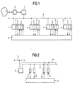
- FIG 1 there is a distributed automation system in usually from a higher-level central unit 1 and more Peripheral control unit 2.
- the central unit 1 and the Peripheral control unit 2 communicate via, for example a serial fieldbus 3, e.g. according to the PROFIBUS protocol, together.
- the peripheral control unit 2 exists - see also FIG 2 - each from a head module 4, input modules 5 and Output modules 6.
- the modules 4-6 of each peripheral control unit 2 are interconnected via a control unit bus 7 connected.
- the control unit bus 7 can optionally be a serial one or a parallel bus 7.
- the input and output modules 5, 6 read process data cyclically from a technical system 8 to be controlled Process data to this. You provide the read Process data ready for the head modules 4. There will be the A time stamp is assigned to process data and a - at least partially - further processing. If necessary the process data from the head modules 4 to the Central unit 1 forwarded.
- the central unit 1 communicates usually via a suitable interface 9, z. B. a computer monitor with an input keyboard and a Mouse, with one user.
- the head assemblies 4 each have a microprocessor 10 on.
- As part of the processing of the computer program product 11 communicates the head assembly 4 with the Central unit 1 and the input and output modules assigned to it 5, 6.
- the head assembly 4 also has a buffer 12 and a timer 13.
- the buffer 12 is used for Buffering of process data and one of the process data if applicable, assigned time stamp.
- the timestamp is determined by querying the timer 13.
- the microprocessor 10 can be seen on the one hand with the serial Fieldbus 3 and on the other hand with the control unit bus 7 connected.
- the control unit bus 7 has its own Signaling signal line 14 via which a signaling signal can be transmitted which will be discussed in more detail later becomes.
- each input module 5 has a microcontroller 15 on.
- the microcontroller 15 also works Computer program product 16 starting the operation of the input module 5 controls.
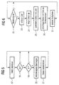
- the microcontroller 15 first reads according to a step 17 Process data from the technical system to be controlled 8 in the respective input module 5. Then the microcontroller takes 15 in steps 18 and 19 preprocessing the process data read into the input module 5. In particular the microcontroller checks in step 18 whether the Process data as such are possible. So he takes one Plausibility check. Step 19 then checks whether whether the process data is different from that of the previous cycle have changed the read process data. Only if the process data are both plausible and there has been a change , subsequent steps 20, 21 are carried out.
- step 20 could also take place before Check for plausibility and / or changes.
- step 20 immediately, that is, promptly for reading a process signal in the input module 5 the head assembly 4 transmitted.
- the transmission of the message signal takes place with high priority via the signaling line 14.
- step 21 the read process data for the head assembly 4 provided.
- the process data is provided at a low priority at the process data interface of the rest of the control unit bus 7, i.e. without paying attention to the signal signal line 14th
- Steps 17 to 21 are usually processed cyclically. After the processing of step 21 started again with the processing of step 17.
- the head assembly 4 generally operates its program cyclically from. 6, this includes steps 22 in particular until 27.
- Step 22 a query is made as to whether a signal from a the input modules 5 was transmitted. If so, in Step 23 records the time by querying the timer 13, a timestamp is determined. Get the timestamp takes place immediately after receipt of the notification signal. The determined time stamp is stored in the buffer 12 deposited.
- step 24 the corresponding process data queried by the signaling input module 5.
- the process data are also stored in the buffer store 12.
- the previously determined time stamp is assigned to you. If necessary, the imported process data and the time stamp assigned to them in step 26 provided for the higher-level central unit 1. Further in step 27 further tasks are carried out, which in the context of the present invention are not of concern. After that the process continues with step 22.
- the operating method according to the invention is without additional Hardware expenditure compared to the prior art and with only very little additional software effort a significant increase in the state of the art Accuracy of the timestamp achievable.
- the Accuracy of the timestamp is now independent of the delay between reading the process data and making it available the process data and also regardless of the transmission duration.
Abstract
Description
Betriebsverfahren für eine aus einer Kopfbaugruppe und mindestens einer Eingabebaugruppe bestehende PeripheriesteuereinheitOperating procedures for a head assembly and at least one an input module existing peripheral control unit
Die vorliegende Erfindung betrifft ein Betriebsverfahren für eine aus einer Kopfbaugruppe und mindestens einer Eingabebaugruppe bestehende Peripheriesteuereinheit, wobei von der Eingabebaugruppe Prozessdaten in die Eingabebaugruppe eingelesen und danach an die Kopfbaugruppe bereitgestellt werden, wobei die Kopfbaugruppe den bereitgestellten Prozessdaten einen Zeitstempel zuordnet.The present invention relates to an operating method for one from a head assembly and at least one input assembly existing peripheral control unit, being from the input module Process data read into the input module and then provided to the head assembly, wherein the head assembly matches the process data provided Assigned timestamp.
Peripheriesteuereinheit, die aus einer Kopfbaugruppe und - meist mehreren - Ein- und Ausgabebaugruppen bestehen, sind z.B. bei PROFIBUS-Systemen bekannt. Sie bilden dort einen so genannten DP-Slave.Peripheral control unit consisting of a head assembly and - usually several - there are input and output modules e.g. known for PROFIBUS systems. You form one like that named DP slave.
Im Stand der Technik arbeiten die einzelnen Baugruppen der Peripheriesteuereinheit asynchron. Insbesondere bearbeiten die Eingabebaugruppen ihren gesamten Zyklus inklusive aller Diagnosen und Weiterverarbeitungen zu Ende und stellen erst dann ihre Prozessdaten für die Kopfbaugruppe bereit. Diese liest dann an der entsprechenden Stelle ihres eigenen Bearbeitungszyklus die Prozessdaten in die Kopfbaugruppe ein, überprüft sie auf Signaländerungen und speichert sie im Änderungsfall mit der zum Zeitpunkt des Einlesens in die Kopfbaugruppe gültigen Uhrzeit ab.In the prior art, the individual components of the Peripheral control unit asynchronous. Edit in particular the input modules their entire cycle including all Diagnoses and further processing come to an end and make only then your process data are ready for the head assembly. This then reads at the appropriate point in their own machining cycle the process data into the head module, checks them for signal changes and saves them in the event of a change with that at the time of reading into the head assembly valid time.
Diese Vorgehensweise kann zu Abweichungen zwischen der abgespeicherten Zeit und der Zeit, zu der die Prozessdaten in die Eingabebaugruppe eingelesen wurden, von mehreren Millisekunden führen.This procedure can lead to deviations between the stored Time and the time at which the process data in the Input module were read in by several milliseconds to lead.
Es ist zwar denkbar, die Eingabebaugruppen mit eigenen Zeitgebern zu versehen und beim Einlesen der Prozessdaten diesen sofort einen Zeitstempel zuzuordnen. In diesem Fall müssten aber nicht nur auf den Eingabebaugruppen Uhrenbausteine vorgesehen werden, sondern darüber hinaus auch diese untereinander und mit dem Uhrenbaustein der Kopfbaugruppe synchronisiert werden. Dies führt zu vergleichsweise hohen Kosten und belastet darüber hinaus die übrige Kommunikation zwischen den einzelnen Baugruppen.It is conceivable that the input modules with their own timers to be provided and when reading in the process data assign a timestamp immediately. In this case but not only provided for clock modules on the input modules but also among themselves and synchronized with the clock module of the head assembly become. This leads to comparatively high costs and also impairs the rest of the communication between the individual assemblies.
Die Aufgabe der vorliegenden Erfindung besteht darin, ein kostengünstiges und effektives Betriebsverfahren für eine aus einer Kopfbaugruppe und mindestens einer Eingabebaugruppe bestehende Peripheriesteuereinheit zu schaffen, mittels dessen eine genaue Zeitstempelzuordnung zu den eingelesenen Prozessdaten möglich ist.The object of the present invention is a inexpensive and effective operating method for a a head assembly and at least one input assembly To create peripheral control unit, by means of which an exact time stamp assignment to the imported process data is possible.
Die Aufgabe wird dadurch gelöst, dass von der Eingabebaugruppe zeitnah zum Einlesen der Prozessdaten ein Meldesignal an die Kopfbaugruppe übermittelt wird und dass die Kopfbaugruppe den Zeitstempel aufgrund des Empfangs des Meldesignals ermittelt.The task is solved by the input module a signal signal promptly for reading in the process data the head assembly is communicated and that the head assembly determines the time stamp based on the receipt of the message signal.
Wenn das Übermitteln des Meldesignals hochprior und das Bereitstellen der Prozessdaten niederprior erfolgt, ist gewährleistet, dass das Meldesignal stets zeitnah zum Einlesen der Prozessdaten an die Kopfbaugruppe übermittelt wird.If the transmission of the alarm signal is high priority and the provision the process data is given a low priority, it is guaranteed that the message signal is always timely to read the Process data is transmitted to the head assembly.
Wenn das Meldesignal der Kopfbaugruppe über eine eigene Meldesignalleitung übermittelt wird, kann das Übermitteln des Meldesignals auch während des Austauschs von Prozessdaten zwischen anderen Baugruppen der Peripheriesteuereinheit erfolgen.If the alarm signal of the head module is via its own alarm signal line is transmitted, the transmission of the Message signals also during the exchange of process data between other modules of the peripheral control unit.
Wenn die in die Eingabebaugruppe eingelesenen Prozessdaten von der Eingabebaugruppe vorverarbeitet werden und das Meldesignal nur dann an die Kopfbaugruppe übermittelt wird, wenn die Eingabebaugruppe aufgrund der Vorverarbeitung einen Aktualisierungsbedarf für die Prozessdaten erkennt, wird der Prozessdatenaustausch zwischen der Eingabebaugruppe und der Kopfbaugruppe so gering wie möglich gehalten. Die Vorverarbeitung der Prozessdaten umfasst vorzugsweise insbesondere auch eine Plausibilitätsprüfung der in die Eingabebaugruppe eingelesen Prozessdaten.If the process data read into the input module are preprocessed by the input module and the message signal is only transmitted to the head assembly if the input module needs to be updated due to the preprocessing for the process data is recognized, the process data exchange between the input module and the Head assembly kept as low as possible. The preprocessing the process data preferably includes in particular also a plausibility check of the input module read process data.
Die Peripheriesteuereinheit ist in der Regel in ein größeres Automatisierungssystem eingebunden. Die Kopfbaugruppe stellt die Prozessdaten daher in der Regel für eine ihr übergeordnete Zentraleinheit bereit.The peripheral control unit is usually in a larger size Automation system integrated. The head assembly provides the process data therefore usually for a higher-level one Central unit ready.
Weitere Vorteile und Einzelheiten ergeben sich aus der nachfolgenden Beschreibung eines Ausführungsbeispiels in Verbindung mit den Zeichnungen. Dabei zeigen in Prinzipdarstellung
- FIG 1
- ein verteiltes Automatisierungssystem,
- FIG 2
- eine Peripheriesteuereinheit,
- FIG 3
- eine Kopfbaugruppe,
- FIG 4
- eine Eingabebaugruppe und
- FIG 5 und 6
- Ablaufdiagramme.
- FIG. 1
- a distributed automation system,
- FIG 2
- a peripheral control unit,
- FIG 3
- a head assembly,
- FIG 4
- an input module and
- 5 and 6
- Flowcharts.
Gemäß FIG 1 besteht ein verteiltes Automatisierungssystem in
der Regel aus einer übergeordneten Zentraleinheit 1 und mehreren
Peripheriesteuereinheit 2. Die Zentraleinheit 1 und die
Peripheriesteuereinheit 2 kommunizieren beispielsweise über
einen seriellen Feldbus 3, z.B. gemäß dem PROFIBUS-Protokoll,
miteinander.According to FIG 1 there is a distributed automation system in
usually from a higher-level central unit 1 and more
Die Peripheriesteuereinheit 2 bestehen - siehe auch FIG 2 -
jeweils aus einer Kopfbaugruppe 4, Eingabebaugruppen 5 und
Ausgabebaugruppen 6. Die Baugruppen 4-6 jeder Peripheriesteuereinheit
2 sind über einen Steuereinheitsbus 7 miteinander
verbunden. Der Steuereinheitsbus 7 kann wahlweise ein serieller
oder ein paralleler Bus 7 sein.The
Die Ein- und Ausgabebaugruppen 5, 6 lesen zyklisch Prozessdaten
von einer zu steuernden technischen Anlage 8 ein bzw. geben
Prozessdaten an diese aus. Sie stellen die eingelesenen
Prozessdaten für die Kopfbaugruppen 4 bereit. Dort wird den
Prozessdaten ein Zeitstempel zugeordnet und es erfolgt eine -
zumindest teilweise - Weiterverarbeitung. Soweit erforderlich,
werden die Prozessdaten von den Kopfbaugruppen 4 an die
Zentraleinheit 1 weiterübermittelt. Die Zentraleinheit 1 kommuniziert
in der Regel über eine geeignete Schnittstelle 9,
z. B. einen Computermonitor mit einer Eingabetastatur und einer
Maus, mit einem Anwender.The input and
Gemäß FIG 3 weisen die Kopfbaugruppen 4 je einen Mikroprozessor
10 auf. Dieser arbeitet ein Computerprogrammprodukt 11
ab, welches den Betrieb der jeweiligen Kopfbaugruppe 4 steuert.
Im Rahmen der Abarbeitung des Computerprogrammprodukts
11 kommuniziert die Kopfbaugruppe 4 unter anderem mit der
Zentraleinheit 1 und den ihr zugeordneten Ein- und Ausgabebaugruppen
5, 6.According to FIG 3, the
Die Kopfbaugruppe 4 weist ferner einen Zwischenspeicher 12
und einen Zeitgeber 13 auf. Der Zwischenspeicher 12 dient zum
Zwischenspeichern von Prozessdaten sowie eines den Prozessdaten
gegebenenfalls zugeordneten Zeitstempels. Der Zeitstempel
wird durch Abfragen des Zeitgebers 13 ermittelt.The
Ersichtlich ist der Mikroprozessor 10 einerseits mit dem seriellen
Feldbus 3 und andererseits mit dem Steuereinheitsbus
7 verbunden. Der Steuereinheitsbus 7 weist dabei eine eigene
Meldesignalleitung 14 auf, über die ein Meldesignal übermittelbar
ist, auf das später noch näher eingegangen werden
wird.The
Gemäß FIG 4 weist jede Eingabebaugruppe 5 einen Mikrocontroller
15 auf. Der Mikrocontroller 15 arbeitet ebenfalls ein
Computerprogrammprodukt 16 ab, das den Betrieb der Eingabebaugruppe
5 steuert. According to FIG. 4, each
Im Rahmen der Abarbeitung des Computerprogrammprodukts 16
liest der Mikrocontroller 15 gemäß einem Schritt 17 zunächst
Prozessdaten von der zu steuernden technischen Anlage 8 in
die jeweilige Eingabebaugruppe 5 ein. Danach nimmt der Mikrocontroller
15 in Schritten 18 und 19 eine Vorverarbeitung der
in die Eingabebaugruppe 5 eingelesenen Prozessdaten vor. Insbesondere
prüft der Mikrocontroller im Schritt 18, ob die
Prozessdaten als solche möglich sind. Er nimmt also eine
Plausibilitätsprüfung vor. Im Schritt 19 wird dann überprüft,
ob sich die Prozessdaten gegenüber den beim vorherigen Zyklus
eingelesenen Prozessdaten geändert haben. Nur wenn die Prozessdaten
sowohl plausibel sind als auch eine Änderung erfolgt
ist, werden nachfolgende Schritte 20, 21 durchlaufen.
Das Übermitteln des Meldesignals an die Kopfbaugruppe 4 und
das Bereitstellen der Prozessdaten für die Kopfbaugruppe 4
erfolgt also nur dann wenn die Eingabebaugruppe 5 aufgrund
der Vorverarbeitung einen Aktualisierungsbedarf für die Daten
erkennt. Der Schritt 20 könnte alternativ aber auch vor der
Prüfung auf Plausibilität und/oder Änderungen erfolgen.As part of the processing of the
Im Schritt 20 wird unverzüglich, also zeitnah zum Einlesen
der Prozessdaten in die Eingabebaugruppe 5 ein Meldesignal an
die Kopfbaugruppe 4 übermittelt. Das Übermitteln des Meldesignals
erfolgt hochprior über die Meldesignalleitung 14.In
Nach dem Übermitteln des Meldesignals werden im Schritt 21
die eingelesenen Prozessdaten für die Kopfbaugruppe 4 bereitgestellt.
Das Bereitstellen der Prozessdaten erfolgt niederprior
an der Prozessdatenschnittstelle des restlichen Steuereinheitsbusses
7, also ohne Beachtung der Meldesignalleitung
14.After the message signal has been transmitted, in
Das Abarbeiten der Schritte 17 bis 21 erfolgt in der Regel
zyklisch. Nach der Abarbeitung des Schrittes 21 wird also
wieder mit der Abarbeitung des Schrittes 17 begonnen.
Die Kopfbaugruppe 4 arbeitet ihr Programm in der Regel zyklisch
ab. Dieses umfasst gemäß FIG 6 insbesondere Schritte 22
bis 27.The
Im Schritt 22 wird abgefragt, ob ein Meldesignal von einer
der Eingabebaugruppen 5 übermittelt wurde. Wenn ja, wird im
Schritt 23 durch Abfragen des Zeitgebers 13 die Zeit erfasst,
also ein Zeitstempel ermittelt. Das Ermitteln des Zeitstempels
erfolgt also unverzüglich nach dem Empfang des Meldesignals.
Der ermittelte Zeitstempel wird im Zwischenspeicher 12
hinterlegt.In
Sodann werden im Schritt 24 die korrespondierenden Prozessdaten
von der signalisierenden Eingabebaugruppe 5 abgefragt.
Die Prozessdaten werden ebenfalls im Zwischenspeicher 12 abgespeichert.
Ihnen wird der zuvor ermittelte Zeitstempel zugeordnet.
Soweit erforderlich, werden die eingelesenen Prozessdaten
und der ihnen zugeordnete Zeitstempel im Schritt 26
für die übergeordnete Zentraleinheit 1 bereitgestellt. Ferner
werden im Schritt 27 weitere Aufgaben ausgeführt, die im Rahmen
der vorliegenden Erfindung nicht von Belang sind. Danach
wird wieder mit dem Schritt 22 fortgefahren.Then in
Mittels des erfindungsgemäßen Betriebsverfahrens ist ohne zusätzlichen Hardwareaufwand gegenüber dem Stand der Technik und mit nur sehr geringem zusätzlichem Softwareaufwand gegenüber dem Stand der Technik eine erhebliche Steigerung bei der Genauigkeit des Zeitstempels erreichbar. Insbesondere ist die Genauigkeit des Zeitstempels nunmehr unabhängig von der Verzögerung zwischen dem Einlesen der Prozessdaten und dem Bereitstellen der Prozessdaten und auch unabhängig von der Übertragungsdauer.By means of the operating method according to the invention is without additional Hardware expenditure compared to the prior art and with only very little additional software effort a significant increase in the state of the art Accuracy of the timestamp achievable. In particular, the Accuracy of the timestamp is now independent of the delay between reading the process data and making it available the process data and also regardless of the transmission duration.
Claims (12)
dadurch gekennzeichnet, dass von der Eingabebaugruppe (5) zeitnah zum Einlesen der Prozessdaten ein Meldesignal an die Kopfbaugruppe (4) übermittelt wird und dass die Kopfbaugruppe (4) den Zeitstempel aufgrund des Empfangs des Meldesignals ermittelt.Operating method for a peripheral control unit (2) consisting of a head module (4) and at least one input module (5), process data being read into the input module (5) by the input module (5) and then being provided for the head module (4), the Header module (4) assigns a time stamp to the process data provided,
characterized in that the input module (5) transmits a signal to the head module (4) promptly after the process data is read in, and in that the head module (4) determines the time stamp on the basis of the reception of the message signal.
dadurch gekennzeichnet, dass das Übermitteln des Meldesignals hochprior und das Bereitstellen der Prozessdaten niederprior erfolgt.Operating method according to claim 1,
characterized in that the transmission of the message signal is high priority and the provision of the process data is low priority.
dadurch gekennzeichnet, dass das Meldesignal der Kopfbaugruppe über eine eigene Meldesignalleitung (14) übermittelt wird.Operating method according to claim 1 or 2,
characterized in that the message signal of the head assembly is transmitted via a separate message signal line (14).
dadurch gekennzeichnet,
characterized,
dadurch gekennzeichnet, dass die Vorverarbeitung der Prozessdaten eine Plausibilitätsprüfung der in die Eingabebaugruppe (5) eingelesenen Prozessdaten umfasst.Operating method according to claim 4,
characterized in that the preprocessing of the process data comprises a plausibility check of the process data read into the input module (5).
dadurch gekennzeichnet, dass die für die Kopfbaugruppe (4) bereitgestellten Prozessdaten von der Kopfbaugruppe (4) für eine der Kopfbaugruppe (4) übergeordnete Zentraleinheit (1) bereitgestellt werden.Operating method according to one of the above claims,
characterized in that the process data provided for the head assembly (4) is provided by the head assembly (4) for a central unit (1) superordinate to the head assembly (4).
dadurch gekennzeichnet, dass sie mit einem Computerprogrammprodukt (11) nach Anspruch 7 programmiert ist.Head assembly according to claim 8,
characterized in that it is programmed with a computer program product (11) according to claim 7.
dadurch gekennzeichnet, dass sie mit einem Computerprogrammprodukt (16) nach Anspruch 10 programmiert ist.Input module according to claim 11,
characterized in that it is programmed with a computer program product (16) according to claim 10.
Applications Claiming Priority (2)
| Application Number | Priority Date | Filing Date | Title |
|---|---|---|---|
| DE10040468A DE10040468A1 (en) | 2000-08-18 | 2000-08-18 | Operating method for a peripheral control unit consisting of a head assembly and at least one input assembly |
| DE10040468 | 2000-08-18 |
Publications (3)
| Publication Number | Publication Date |
|---|---|
| EP1184755A2 true EP1184755A2 (en) | 2002-03-06 |
| EP1184755A3 EP1184755A3 (en) | 2006-07-19 |
| EP1184755B1 EP1184755B1 (en) | 2008-03-19 |
Family
ID=7652905
Family Applications (1)
| Application Number | Title | Priority Date | Filing Date |
|---|---|---|---|
| EP01119059A Expired - Lifetime EP1184755B1 (en) | 2000-08-18 | 2001-08-07 | Method for operating a peripheral unit comprising one main group and at least one input group |
Country Status (4)
| Country | Link |
|---|---|
| EP (1) | EP1184755B1 (en) |
| AT (1) | ATE389906T1 (en) |
| DE (2) | DE10040468A1 (en) |
| ES (1) | ES2299453T3 (en) |
Cited By (3)
| Publication number | Priority date | Publication date | Assignee | Title |
|---|---|---|---|---|
| FR2848313A1 (en) * | 2002-12-06 | 2004-06-11 | Avensy | Computer assisted production tracking system includes real time system time and date stamping all records of machine processes for recording in file |
| WO2007101658A1 (en) * | 2006-03-08 | 2007-09-13 | Pepperl + Fuchs Gmbh | Method for recording input signal variations |
| EP2455830A1 (en) * | 2010-11-23 | 2012-05-23 | Siemens Aktiengesellschaft | Method for recording changes in entry signals |
Families Citing this family (1)
| Publication number | Priority date | Publication date | Assignee | Title |
|---|---|---|---|---|
| DE102009017681B4 (en) * | 2009-04-16 | 2014-02-20 | Phoenix Contact Gmbh & Co. Kg | Method and communication system for determining the time of an event in an IO device |
Citations (5)
| Publication number | Priority date | Publication date | Assignee | Title |
|---|---|---|---|---|
| US4550382A (en) * | 1982-09-21 | 1985-10-29 | Xerox Corporation | Filtered inputs |
| DE4408488A1 (en) * | 1994-03-14 | 1995-09-21 | Bosch Gmbh Robert | Method for the cyclical transmission of data between at least two distributed control units |
| WO1996001979A1 (en) * | 1994-07-07 | 1996-01-25 | Westinghouse Electric Corporation | Apparatus attaching occurrence time to sensor signals |
| EP0903655A2 (en) * | 1997-09-22 | 1999-03-24 | Hewlett-Packard Company | Control system with nodes |
| US5933347A (en) * | 1997-06-13 | 1999-08-03 | Allen-Bradley Company Llc | Industrial controller with program synchronized updating of back-up controller |
-
2000
- 2000-08-18 DE DE10040468A patent/DE10040468A1/en not_active Ceased
-
2001
- 2001-08-07 DE DE50113746T patent/DE50113746D1/en not_active Expired - Lifetime
- 2001-08-07 AT AT01119059T patent/ATE389906T1/en not_active IP Right Cessation
- 2001-08-07 EP EP01119059A patent/EP1184755B1/en not_active Expired - Lifetime
- 2001-08-07 ES ES01119059T patent/ES2299453T3/en not_active Expired - Lifetime
Patent Citations (5)
| Publication number | Priority date | Publication date | Assignee | Title |
|---|---|---|---|---|
| US4550382A (en) * | 1982-09-21 | 1985-10-29 | Xerox Corporation | Filtered inputs |
| DE4408488A1 (en) * | 1994-03-14 | 1995-09-21 | Bosch Gmbh Robert | Method for the cyclical transmission of data between at least two distributed control units |
| WO1996001979A1 (en) * | 1994-07-07 | 1996-01-25 | Westinghouse Electric Corporation | Apparatus attaching occurrence time to sensor signals |
| US5933347A (en) * | 1997-06-13 | 1999-08-03 | Allen-Bradley Company Llc | Industrial controller with program synchronized updating of back-up controller |
| EP0903655A2 (en) * | 1997-09-22 | 1999-03-24 | Hewlett-Packard Company | Control system with nodes |
Cited By (5)
| Publication number | Priority date | Publication date | Assignee | Title |
|---|---|---|---|---|
| FR2848313A1 (en) * | 2002-12-06 | 2004-06-11 | Avensy | Computer assisted production tracking system includes real time system time and date stamping all records of machine processes for recording in file |
| WO2004053607A1 (en) * | 2002-12-06 | 2004-06-24 | Avensy | Computer-assisted production tracking system with production data traceability |
| WO2007101658A1 (en) * | 2006-03-08 | 2007-09-13 | Pepperl + Fuchs Gmbh | Method for recording input signal variations |
| EP2455830A1 (en) * | 2010-11-23 | 2012-05-23 | Siemens Aktiengesellschaft | Method for recording changes in entry signals |
| US8775852B2 (en) | 2010-11-23 | 2014-07-08 | Siemens Aktiengesellschaft | Method for sensing input signal changes |
Also Published As
| Publication number | Publication date |
|---|---|
| DE10040468A1 (en) | 2002-03-07 |
| ES2299453T3 (en) | 2008-06-01 |
| EP1184755B1 (en) | 2008-03-19 |
| EP1184755A3 (en) | 2006-07-19 |
| ATE389906T1 (en) | 2008-04-15 |
| DE50113746D1 (en) | 2008-04-30 |
Similar Documents
| Publication | Publication Date | Title |
|---|---|---|
| EP2621193B1 (en) | Device for transmitting sensor data | |
| EP0917034B1 (en) | Method for remote monitoring and/or remote servicing of an injection moulding machine | |
| EP0678796A1 (en) | Compact programmable logic controller and central unit of a modular programmable logic controller | |
| DE102009045386A1 (en) | Method for operating a fieldbus interface | |
| EP3019920B1 (en) | Data-capture unit and automation system | |
| DE102014106752A1 (en) | Method and control device for operating a non-contact transmission system for an IO-Link | |
| WO2002075509A2 (en) | Synchronous, clocked communication system with a relative time clock and method for establishing such a system | |
| EP0791874B1 (en) | Method and apparatus for controlling binary sensors and/or actuators | |
| EP2544388B1 (en) | Method for cycle and time unit synchronisation in an automation network | |
| EP1253494B1 (en) | Control device with field bus | |
| EP3814856B1 (en) | Real time automation device with a real-time data bus | |
| EP1802043B1 (en) | Communications structure | |
| EP1184755B1 (en) | Method for operating a peripheral unit comprising one main group and at least one input group | |
| EP1903530B1 (en) | Assembly with vacuum device and method for its operation | |
| DE10131944A1 (en) | Processes for processing data | |
| EP2746892B1 (en) | Automated system and method for synchronising an automated system | |
| DE102010064123B3 (en) | Method for controlling peripheral devices of an isochronous bus system and third party peripheral devices of a third-party bus system and associated bus converter | |
| EP2641210B1 (en) | Control of networked bus participants | |
| DE10237097B4 (en) | Correction of signal propagation times in distributed communication systems | |
| EP1454201A1 (en) | Engineering and automation system | |
| EP1170645A2 (en) | Method and arrangement for monitoring and controlling machines, such as machine installations | |
| EP3632055B1 (en) | Transmission of data on a local bus | |
| DE102006042949A1 (en) | Communication network with main participants and topology servers | |
| EP1374000B1 (en) | Method and assembly for operating and/or observing the device that monitors installation control | |
| EP2315090A1 (en) | Real-time control method for a control apparatus for a industrial technical process and real-time operating method for a computing apparatus |
Legal Events
| Date | Code | Title | Description |
|---|---|---|---|
| PUAI | Public reference made under article 153(3) epc to a published international application that has entered the european phase |
Free format text: ORIGINAL CODE: 0009012 |
|
| AK | Designated contracting states |
Kind code of ref document: A2 Designated state(s): AT BE CH CY DE DK ES FI FR GB GR IE IT LI LU MC NL PT SE TR |
|
| AX | Request for extension of the european patent |
Free format text: AL;LT;LV;MK;RO;SI |
|
| PUAL | Search report despatched |
Free format text: ORIGINAL CODE: 0009013 |
|
| AK | Designated contracting states |
Kind code of ref document: A3 Designated state(s): AT BE CH CY DE DK ES FI FR GB GR IE IT LI LU MC NL PT SE TR |
|
| AX | Request for extension of the european patent |
Extension state: AL LT LV MK RO SI |
|
| 17P | Request for examination filed |
Effective date: 20060821 |
|
| AKX | Designation fees paid |
Designated state(s): AT CH DE ES FR GB LI |
|
| GRAP | Despatch of communication of intention to grant a patent |
Free format text: ORIGINAL CODE: EPIDOSNIGR1 |
|
| GRAS | Grant fee paid |
Free format text: ORIGINAL CODE: EPIDOSNIGR3 |
|
| GRAA | (expected) grant |
Free format text: ORIGINAL CODE: 0009210 |
|
| AK | Designated contracting states |
Kind code of ref document: B1 Designated state(s): AT CH DE ES FR GB LI |
|
| REG | Reference to a national code |
Ref country code: GB Ref legal event code: FG4D Free format text: NOT ENGLISH |
|
| GBT | Gb: translation of ep patent filed (gb section 77(6)(a)/1977) |
Effective date: 20080319 |
|
| REG | Reference to a national code |
Ref country code: CH Ref legal event code: NV Representative=s name: SIEMENS SCHWEIZ AG Ref country code: CH Ref legal event code: EP |
|
| REF | Corresponds to: |
Ref document number: 50113746 Country of ref document: DE Date of ref document: 20080430 Kind code of ref document: P |
|
| REG | Reference to a national code |
Ref country code: ES Ref legal event code: FG2A Ref document number: 2299453 Country of ref document: ES Kind code of ref document: T3 |
|
| ET | Fr: translation filed | ||
| PGFP | Annual fee paid to national office [announced via postgrant information from national office to epo] |
Ref country code: ES Payment date: 20080911 Year of fee payment: 8 |
|
| PGFP | Annual fee paid to national office [announced via postgrant information from national office to epo] |
Ref country code: AT Payment date: 20080709 Year of fee payment: 8 |
|
| PLBE | No opposition filed within time limit |
Free format text: ORIGINAL CODE: 0009261 |
|
| STAA | Information on the status of an ep patent application or granted ep patent |
Free format text: STATUS: NO OPPOSITION FILED WITHIN TIME LIMIT |
|
| PGFP | Annual fee paid to national office [announced via postgrant information from national office to epo] |
Ref country code: CH Payment date: 20081106 Year of fee payment: 8 |
|
| 26N | No opposition filed |
Effective date: 20081222 |
|
| REG | Reference to a national code |
Ref country code: CH Ref legal event code: PCAR Free format text: SIEMENS SCHWEIZ AG;INTELLECTUAL PROPERTY FREILAGERSTRASSE 40;8047 ZUERICH (CH) |
|
| REG | Reference to a national code |
Ref country code: CH Ref legal event code: PL |
|
| PG25 | Lapsed in a contracting state [announced via postgrant information from national office to epo] |
Ref country code: LI Free format text: LAPSE BECAUSE OF NON-PAYMENT OF DUE FEES Effective date: 20090831 Ref country code: CH Free format text: LAPSE BECAUSE OF NON-PAYMENT OF DUE FEES Effective date: 20090831 |
|
| PG25 | Lapsed in a contracting state [announced via postgrant information from national office to epo] |
Ref country code: AT Free format text: LAPSE BECAUSE OF NON-PAYMENT OF DUE FEES Effective date: 20090807 |
|
| REG | Reference to a national code |
Ref country code: ES Ref legal event code: FD2A Effective date: 20090808 |
|
| PG25 | Lapsed in a contracting state [announced via postgrant information from national office to epo] |
Ref country code: ES Free format text: LAPSE BECAUSE OF NON-PAYMENT OF DUE FEES Effective date: 20090808 |
|
| REG | Reference to a national code |
Ref country code: FR Ref legal event code: PLFP Year of fee payment: 16 |
|
| REG | Reference to a national code |
Ref country code: FR Ref legal event code: PLFP Year of fee payment: 17 |
|
| REG | Reference to a national code |
Ref country code: FR Ref legal event code: PLFP Year of fee payment: 18 |
|
| PGFP | Annual fee paid to national office [announced via postgrant information from national office to epo] |
Ref country code: FR Payment date: 20200813 Year of fee payment: 20 Ref country code: GB Payment date: 20200916 Year of fee payment: 20 |
|
| PGFP | Annual fee paid to national office [announced via postgrant information from national office to epo] |
Ref country code: DE Payment date: 20201019 Year of fee payment: 20 |
|
| REG | Reference to a national code |
Ref country code: DE Ref legal event code: R071 Ref document number: 50113746 Country of ref document: DE |
|
| REG | Reference to a national code |
Ref country code: GB Ref legal event code: PE20 Expiry date: 20210806 |
|
| PG25 | Lapsed in a contracting state [announced via postgrant information from national office to epo] |
Ref country code: GB Free format text: LAPSE BECAUSE OF EXPIRATION OF PROTECTION Effective date: 20210806 |