EP1184687A2 - Polarizing filter and optical device using the same - Google Patents
Polarizing filter and optical device using the same Download PDFInfo
- Publication number
- EP1184687A2 EP1184687A2 EP01120651A EP01120651A EP1184687A2 EP 1184687 A2 EP1184687 A2 EP 1184687A2 EP 01120651 A EP01120651 A EP 01120651A EP 01120651 A EP01120651 A EP 01120651A EP 1184687 A2 EP1184687 A2 EP 1184687A2
- Authority
- EP
- European Patent Office
- Prior art keywords
- layers
- refractive index
- polarizing filter
- group
- layer
- Prior art date
- Legal status (The legal status is an assumption and is not a legal conclusion. Google has not performed a legal analysis and makes no representation as to the accuracy of the status listed.)
- Withdrawn
Links
Images





Classifications
-
- G—PHYSICS
- G02—OPTICS
- G02B—OPTICAL ELEMENTS, SYSTEMS OR APPARATUS
- G02B5/00—Optical elements other than lenses
- G02B5/30—Polarising elements
- G02B5/3025—Polarisers, i.e. arrangements capable of producing a definite output polarisation state from an unpolarised input state
Definitions
- the present invention relates to a polarizing filter used for controlling a state of polarization of light to be dealt with, and an optical device using the polarizing filter in an optical technology field such as optical communication, an optical sensor, an optical measuring device, and so on.
- incident light propagated through an optical fiber often contains an s-polarized light component and a p-polarized light component in an unequal intensity ratio. It is therefore necessary to provide a polarizing/optical device having a function for compensating for such incident light into a state of non-polarized light equal in the intensity ratio of the s-polarized light component to the p-polarized light component or for polarizing non-polarized incident light to obtain a desired intensity ratio of the s-polarized light component to the p-polarized light component.
- a polarization beam splitter having a configuration in which tens of layers of high-refractive-index materials and low-refractive-index materials are laminated alternately on a transparent prism or on a flat transparent substrate.
- the polarization beam splitter can transmit only the p-polarized light component while it can cut off the s-polarized light component perfectly because an optical multilayer film satisfying the Brewster condition is provided in the polarization beam splitter.
- the polarization beam splitter uses light reflected or transmitted at the Brewster angle, the polarization beam splitter is allowed to use light narrow in the wavelength range, but can obtain the excellent degree of polarization in each of reflected light and transmitted light, high mass-production characteristic and is inexpensive in cost, compared with a polarizer using birefringence of a crystal such as a Nicol prism. For this reason, the polarization beam splitter is used popularly.
- the polarization beam splitter is a device provided for separating incident light into the s-polarized light component and the p-polarized light component perfectly, the polarization beam splitter is, however, unsuitable for compensation for polarized light to obtain light with a desired intensity ratio of the s-polarized light component to the p-polarized light component.
- the transmittance ratio of the s-polarized light component to the p-polarized light component varies when light is made incident obliquely on a transparent flat plate such as a glass plate.
- a polarizing filter using this characteristic is rather suitable for light compensation than the polarization beam splitter.
- the present invention is devised to solve the aforementioned problems and an object thereof is to provide a polarizing filter which can compensate for incident light to obtain light with a desired intensity ratio of the s-polarized light component to the p-polarized light component, and to provide an optical device using the polarizing filter.
- a polarizing filter is configured as follows. First, a plurality of dielectric materials different from one another in refractive index with respect to a wavelength of incident light are classified into a first group and a second group so that the maximum value among the refractive indices of the dielectric materials belonging to the first group is lower than the minimum value among the refractive indices of the dielectric materials belonging to the second group. At least one layer of dielectric thin film selected from the dielectric materials belonging to the first group and at least one layer of dielectric thin film selected from the dielectric materials belonging to the second group are alternately laminated on a transparent flat substrate to form the laminate structure.
- one layer of the dielectric thin film having a refractive index which is higher than the maximum value selected from the refractive indices of the dielectric materials belonging to the first group and which is lower than the minimum value selected from the refractive indices of the dielectric materials belonging to the second group is laminated on an outermost surface of the laminate structure.
- the dielectric thin film brought in contact with the surface of the substrate may be selected from the first or second group.
- one to four layers of dielectric thin films selected from the first group and one to four layers of dielectric thin films selected from the second group are laminated alternately on the transparent flat substrate so that a sufficient effect can be obtained.
- a refractive index difference with respect to the wavelength of incident light between adjacent dielectric thin films selected from the dielectric materials belonging to the first and second groups respectively is in a range of from 0.15 to 1.2, both inclusively.
- optical film thickness of each of the dielectric thin films is in a range of 0.25 ⁇ ⁇ 0.15 ⁇ in which ⁇ is a wavelength of incident light.
- an angle of incidence on the polarizing filter is in a range of from 20 to 70 degrees.
- the transmitting or reflecting characteristic of a multilayer film structure constituted by an alternate laminate of high-refractive-index layers and low-refractive-index layers depends on polarized light. Generally, at least ten layers are required for perfectly transmitting or reflecting either of the s-polarized light component and p-polarized light component of incident light.
- the degree of polarization is allowed to be relatively low as described above in the object of the present invention, such a multilayer film structure can be realized by a number of layers not larger than 9.
- the stability of optical characteristic increases as the number of layers decreases, because there are more or less variations in the angle of incidence of light, variations in the refractive index of each film material, variations in the film thickness of each layer, and so on. Also taking economy or the like into account, a smaller number of layers are preferred. In the present invention, therefore, the target number of layers is set to be smaller than 10.
- the inventors of the present application have found out a multilayer film configuration from which light in a state of non-polarized light with the transmittance of the s-polarized light component equal to the transmittance of the p-polarized light component can be made to exit when a laminate structure 20 of dielectric films is provided on a substrate 10 as shown in Fig. 1 and the incident angle 7 of incident light 5 in which the intensity ratio of the s-polarized light component to the p-polarized light component is in a range of from 1:1 to 5:1 with respect to a certain wavelength is set.
- the multilayer film configuration is basically made in such a manner that one to four layers of high-refractive-index dielectric thin films 1 and one to four layers of low-refractive-index dielectric thin films 2 are laminated alternately on the substrate 10 and that one dielectric thin film 3 having a refractive index intermediate between the refractive indices of the two kinds of dielectric thin films 1 and 2 is laminated as an uppermost layer on the alternate laminate of the two kinds of dielectric thin films 1 and 2.
- the dielectric thin film laminated first on the substrate is one of the low-refractive-index dielectric thin films.
- the high-refractive-index dielectric thin films maybe constituted by a group of a plurality of dielectric materials different in refractive index
- the low-refractive-index dielectric thin films maybe also constituted by a group of a plurality of dielectric materials different in refractive index.
- the refractive index of the dielectric in the uppermost layer is set so as to be lower than the minimum refractive index in refractive indices of the high-refractive-index dielectric materials and higher than the maximum refractive index in refractive indices of the low-refractive-index dielectric materials.
- the incident angle 7 of light with respect to a normal line 9 on a surface of the polarizing filter is selected to be in a range of from 20 to 70 degrees, the aforementioned transmittance ratio can be obtained.
- the incident angle 7 is selected to be not higher than 45 degrees so that the size of a housing for an optical device can be kept small when the polarizing filter is applied to the optical device.
- the flat transparent substrate 10 is not particularly limited.
- the surface of the substrate however, needs to be optically flat because an optically coherent effect is used.
- metal oxides such as titanium oxide, tantalum oxide, zirconium oxide, niobium oxide, magnesium oxide, silicon oxide, ytterbium oxide, hafnium oxide, aluminum oxide, etc.
- metal fluorides such as magnesium fluoride, calcium fluoride, lithium fluoride, etc.
- each of the transparent dielectric thin films used in the present invention is not specifically limited. Any method selected from various kinds of film-forming methods such as a vacuum evaporation film-forming method, a sputtering film-forming method, a sol-gel film-forming method, a chemical vapor-phase deposition method (CVD method), an ion-plating method, and so on can be used.
- film-forming methods such as a vacuum evaporation film-forming method, a sputtering film-forming method, a sol-gel film-forming method, a chemical vapor-phase deposition method (CVD method), an ion-plating method, and so on can be used.
- a non-alkali glass substrate with a size of 100 mm x 100 mm x 1.1 mm thick was set in a vacuum evaporation apparatus provided with an oil-diffusion pump.
- the vacuum chamber in the apparatus was exhausted to 0.0025 Pa by using the oil-diffusion pump.
- the glass substrate was heated to 250°C by a substrate heating heater provided in the apparatus.
- a 189 nm-thick titanium oxide film (refractive index: 2.13), a 286 nm-thick silicon oxide film (refractive index: 1.46) and a 268 nm-thick aluminum oxide film (refractive index: 1.62) were formed successively on the glass substrate to thereby produce a multilayer film for use in a polarizing filter.
- the optical film thicknesses of the titanium oxide film, the silicon oxide film and the aluminum oxide film were equivalent to 0.26 ⁇ , 0.27 ⁇ and 0.28 ⁇ respectively when the wavelength ( ⁇ ) of incident light was 1550 nm.
- Each film material was evaporated by electron-beam heating while the glass substrate was rotated in the condition that the distance from an evaporation crucible to the glass substrate was made 100 cm.
- an oxygen gas was introduced so that the pressure became 0.012 Pa.
- no gas was introduced for evaporation of the silicon oxide layer and the aluminum oxide layer.
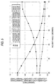
- the transmittance of the s-polarized light component and the transmittance of the p-polarized light component in the case where light with a wavelength of 1550 nm was made incident on the film surface of the polarizing filter obtained as described above were measured while the incident angle (an angle between the incident light and the normal line on the surface of the polarizing filter) was changed variously in a range of from 20 to 70 degrees.
- Fig. 2 shows results of the measurement.
- a 190 nm-thick titanium oxide film, a 322 nm-thick magnesium fluoride film (refractive index: 1.40) and a 286 nm-thick silicon oxide film were formed successively in the same manner as in Example 1 to thereby produce a multilayer film for use in a polarizing filter.
- the optical film thicknesses of the titanium oxide film, the magnesium fluoride film and the silicon oxide film were equivalent to 0.26 ⁇ , 0.29 ⁇ and 0.27 ⁇ respectively when the wavelength ( ⁇ ) of incident light was 1550 nm.
- a 180 nm-thick titanium oxide film, a 265 nm-thick silicon oxide film, a 180 nm-thick titanium oxide film, a 265 nm-thick silicon oxide film, a 180 nm-thick titanium oxide film, a 265 nm-thick silicon oxide film and a 242 nm-thick aluminum oxide film were laminated successively in the same manner as in Example 1 to thereby produce a multilayer film for use in a polarizing filter.
- the optical film thickness of each of the layers was equivalent to 0.25 ⁇ when the wavelength ( ⁇ ) of incident light was 1550 nm.
- a 195 nm-thick titanium oxide film, a 287 nm-thick silicon oxide film, a 195 nm-thick titanium oxide film, a 287 nm-thick silicon oxide film, a 262 nm-thick aluminum oxide film were laminated successively in the same manner as in Example 1 to thereby produce a multilayer film for use in a polarizing filter.
- the optical film thickness of each of the layers was equivalent to 0.27 ⁇ when the wavelength ( ⁇ ) of incident light was 1550 nm.
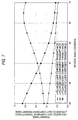
- the transmittance intensity ratio of the s-polarized light component to the p-polarized light component was 1:3.57.
- incident light in a state in which the intensity ratio of the s-polarized light component to the p-polarized light component is 3.57:1 with respect to a wavelength of 1550 nm can be controlled into a non-polarized light state in which the intensity ratio of the s-polarized light component to the p-polarized light component is 1:1.
- a 265 nm-thick magnesium fluoride film, a 229 nm-thick aluminum oxide film, a 265 nm-thick magnesium fluoride film, a 229 nm-thick aluminum oxide film, a 265 nm-thick magnesium fluoride film, a 229 nm-thick aluminum oxide film and a 251 nm-thick silicon oxide film were laminated successively in the same manner as in Example 1 to thereby produce a multilayer film for use in a polarizing filter.
- the optical film thickness of each of the layers was equivalent to 0.24 ⁇ when the wavelength ( ⁇ ) of incident light was 1550 nm.
- a 190 nm-thick titanium oxide film, a 294 nm-thick magnesium fluoride film, a 207 nm-thick zirconium oxide film (refractive index: 1.95), a 279 nm-thick silicon oxide film and a 255 nm-thick aluminum oxide film were laminated successively in the same manner as in Example 1 to thereby produce a multilayer film for use in a polarizing filter.
- the optical film thickness of each of the layers was equivalent to 0.26 ⁇ when the wavelength ( ⁇ ) of incident light was 1550 nm.
- the transmittance of the s-polarized light component and the transmittance of the p-polarized light component in the case where light with a wavelength of 1550 nm was made incident on a soda lime glass plate with a size of 100 mm x 100 mm x 1.0 mm thick were measured while the angle of incidence was changed variously in a range of from 0 to 85 degrees.
- Fig. 8 shows results of the measurement.
- the angle of incidence of light needs to be selected to be about 60 degrees in the case where incident light in a state in which the intensity ratio of the s-polarized light component to the p-polarized light component is 1.43:1 with respect to a wavelength of 1550 nm must be controlled into a state of non-polarized light in which the intensity ratio of the s-polarized light component to the p-polarized light component is 1:1, or the angle of incidence of light needs to be selected to be about 75 degrees in the case where incident light in a state in which the intensity ratio of the s-polarized light component to the p-polarized light component is 2:1 with respect to a wavelength of 1550 nm must be controlled into a state of non-polarized light in which the intensity ratio of the s-polarized light component to the p-polarized light component is 1:1.
- the transmittance of the s-polarized light component and the transmittance of the p-polarized light component in the case where light with a wavelength of 1550 nm was made incident on a quartz glass plate with a size of 100 mm x 100 mm x 1.0 mm thick were measured while the angle of incidence was changed variously in a range of from 0 to 85 degrees.
- Fig. 9 shows results of the measurement.
- the angle of incidence of light needs to be selected to be about 62 degrees in the case where incident light in a state in which the intensity ratio of the s-polarized light component to the p-polarized light component is 1.43:1 with respect to a wavelength of 1550 nm must be controlled into a state of non-polarized light in which the intensity ratio of the s-polarized light component to the p-polarized light component is 1:1, or the angle of incidence of light needs to be selected to be about 85 degrees in the case where incident light in a state in which the intensity ratio of the s-polarized light component to the p-polarized light component is 2:1 with respect to a wavelength of 1550 nm must be controlled into a state of non-polarized light in which the intensity ratio of the s-polarized light component to the p-polarized light component is 1:1.
- the multilayer film for use in the polarizing filter according to the present invention when used, light in which the intensity ratio of the s-polarized light component to the p-polarized light component is in a range of from 1:1 to 5:1 with respect to a certain wavelength can be compensated into a state of non-polarized light in which the transmittance of the s-polarized light component is equal to the transmittance of the p-polarized light component, or non-polarized light with a certain wavelength can be polarized into light in which the transmittance ratio of the s-polarized light component to the p-polarized light component is in a range of from 1:1 to 1:5.
- the angle of incidence of light can be reduced so that the multilayer film can be preferably used in an optical device.
- the multilayer film for use in the polarizing filter according to the present invention is excellent in economy because the number of layers to be laminated can be reduced.
Landscapes
- Physics & Mathematics (AREA)
- General Physics & Mathematics (AREA)
- Optics & Photonics (AREA)
- Polarising Elements (AREA)
- Optical Filters (AREA)
Abstract
Description
Claims (16)
- A polarizing filter having a laminate structure:wherein a plurality of dielectric materials different from one another in refractive index with respect to a wavelength of incident light are classified into a first group and a second group so that a maximum value among the refractive indices of the dielectric materials belonging to said first group is lower than a minimum value among the refractive indices of the dielectric materials belonging to said second group;wherein at least one layer of dielectric thin film selected from the dielectric materials belonging to said first group and at least one layer of dielectric thin film selected from the dielectric materials belonging to said second group are alternately laminated on a transparent flat substrate to form said laminate structure; andwherein one layer of the dielectric thin film having a refractive index which is higher than the maximum value selected from said refractive indices of the dielectric materials belonging to said first group and which is lower than the minimum value selected from said refractive indices of the dielectric materials belonging to said second group is laminated on an outermost surface of said laminate structure.
- A polarizing filter having a laminate structure:wherein a plurality of dielectric materials different from one another in refractive index with respect to a wavelength of incident light are classified into a first group and a second group so that the maximum value among the refractive indices of the dielectric materials belonging to said first group is lower than the minimum value among the refractive indices of the dielectric materials belonging to said second group;wherein at least one layer of dielectric thin film selected from the dielectric materials belonging to said second group and at least one layer of dielectric thin film selected from the dielectric materials belonging to said first group are alternately laminated on a transparent flat to form said laminate structure; andwherein one layer of the dielectric thin film having a refractive index which is higher than the maximum value selected from said refractive indices of the dielectric materials belonging to said first group and which is lower than the minimum value selected from said refractive indices of the dielectric materials belonging to said second group is laminated on an outermost surface of said laminate structure.
- A polarizing filter according to Claim 1 or 2, wherein one to four layers of dielectric thin films selected from said first group and one to four layers of dielectric thin films selected from said second group are laminated alternately on said transparent flat substrate.
- A polarizing filter according to Claim 1, 2 or 3, wherein a refractive index difference with respect to the wavelength of incident light between adjacent dielectric thin films selected from the dielectric materials belonging to said first and second groups respectively is in a range of from 0.15 to 1.2, both inclusively.
- A polarizing filter according to any one of the preceding claims, wherein optical film thickness of each of said dielectric thin films is in a range of 0.25λ ± 0.15λ in which λ is a wavelength of incident light.
- An optical device using a polarizing filter defined in any one of the preceding claims, wherein an angle of incidence on said polarizing filter is in a range of from 20 to 70 degrees.
- A polarizing filter comprising:wherein:a transparent substrate; andat least three layers laminated one on another on said substrate, said at least three layers including an outermost layer having a first refractive index, and odd and even number layers interposed between said outermost layer and said substrate,a refractive index of each said odd number layer is higher than the first refractive index; anda refractive index of each said even number layer is lower than the first refractive index.
- A polarizing filter comprising:wherein:a transparent substrate; andat least three layers laminated one on another on said substrate, said at least three layers including an outermost layer having a first refractive index, and odd and even number layers interposed between said outermost layer and said substrate,a refractive index of each said odd number layer is lower than the first refractive index; anda refractive index of each said even number layer is higher than the first refractive index.
- A polarizing filter according to claim 7 or 8, wherein total number of at least three layers is not larger than seven.
- A polarizing filter according to claim 7, 8 or 9, wherein the first refractive index is 1.62 or 1.46.
- A polarizing filter according to claim 7, wherein said at least three layers are constructed by three layers, the refractive index of the first layer is 2.13, the refractive index of the second layer is 1.46, and the first refractive index of the outermost layer is 1.62.
- A polarizing filter according to claim 7, wherein said at least three layers are constructed by three layers, the refractive index of the first layer is 2.13, the refractive index of the second layer is 1.40, and the first refractive index of the outermost layer is 1.46.
- A polarizing filter according to claim 7, wherein said at least three layers are constructed by seven layers, the refractive indexes of the first to sixth layers are 2.13, 1.46, 2.13, 1.46, 2.13 and 1.46, respectively, and the first refractive index of the outermost layer is 1.62.
- A polarizing filter according to claim 7, wherein. said at least three layers are constructed by five layers, the refractive indexes of the first to fourth layers are 2.13, 1.46, 2.13 and 1.46, respectively, and the first refractive index of the outermost layer is 1.62.
- A polarizing filter according to claim 8, wherein said at least three layers are constructed by seven layers, the refractive indexes of the fist to sixth layers are 1.40, 1.62, 1.40, 1.62, 1.40 and 1.62, respectively, and the first refractive index of the outermost layer is 1.46.
- A polarizing filter according to claim 8, wherein said at least three layers are constructed by five layers, the refractive indexes of the first to fourth layers are 2.13, 1.40, 1.95 and 1.46, respectively, and the first refractive index of the outermost layer is 1.62.
Applications Claiming Priority (2)
| Application Number | Priority Date | Filing Date | Title |
|---|---|---|---|
| JP2000261284A JP2002071946A (en) | 2000-08-30 | 2000-08-30 | Polarizing filter and optical device using the same |
| JP2000261284 | 2000-08-30 |
Publications (2)
| Publication Number | Publication Date |
|---|---|
| EP1184687A2 true EP1184687A2 (en) | 2002-03-06 |
| EP1184687A3 EP1184687A3 (en) | 2003-12-03 |
Family
ID=18749152
Family Applications (1)
| Application Number | Title | Priority Date | Filing Date |
|---|---|---|---|
| EP01120651A Withdrawn EP1184687A3 (en) | 2000-08-30 | 2001-08-30 | Polarizing filter and optical device using the same |
Country Status (4)
| Country | Link |
|---|---|
| US (2) | US6967776B2 (en) |
| EP (1) | EP1184687A3 (en) |
| JP (1) | JP2002071946A (en) |
| CA (1) | CA2355991A1 (en) |
Cited By (1)
| Publication number | Priority date | Publication date | Assignee | Title |
|---|---|---|---|---|
| WO2015034801A3 (en) * | 2013-09-06 | 2015-07-30 | 3M Innovative Properties Company | Head mounted display with eye tracking |
Families Citing this family (13)
| Publication number | Priority date | Publication date | Assignee | Title |
|---|---|---|---|---|
| JP2002071946A (en) * | 2000-08-30 | 2002-03-12 | Nippon Sheet Glass Co Ltd | Polarizing filter and optical device using the same |
| JP2005107317A (en) * | 2003-09-30 | 2005-04-21 | Minolta Co Ltd | Polarized light separation film and polarized light separation prism |
| JP4652122B2 (en) * | 2005-05-18 | 2011-03-16 | 株式会社日立製作所 | Projection-type image display device, optical member and optical unit used therefor |
| JP2007163726A (en) * | 2005-12-13 | 2007-06-28 | Seiko Epson Corp | Projector and optical component |
| US8767301B2 (en) | 2008-01-31 | 2014-07-01 | Hewlett-Packard Development Company, L.P. | MEMS-based pellicle beamsplitter |
| WO2009136914A1 (en) * | 2008-05-06 | 2009-11-12 | Hewlett-Packard Development Company, L.P. | Fabrication of thin pellicle beam splitters |
| US8817371B1 (en) * | 2008-08-01 | 2014-08-26 | Simon Andrew Boothroyd | Polarizing beam splitters |
| TWI386728B (en) * | 2009-01-20 | 2013-02-21 | Au Optronics Corp | Backlight module and liquid crystal display |
| EP2520955A4 (en) * | 2009-10-20 | 2013-06-19 | Sigma Koki Co Ltd | WIDEBAND TYPE BROADBAND DEPOLARIZATION BEAM SEPARATOR |
| RU2622223C1 (en) * | 2016-06-29 | 2017-06-13 | Александр Алексеевич Семенов | Light filter for protection from laser radiation |
| JP6767792B2 (en) * | 2016-07-01 | 2020-10-14 | オリンパス株式会社 | Polarization separation element, optical system and optical equipment |
| JP7418098B2 (en) * | 2019-04-26 | 2024-01-19 | キヤノン株式会社 | Method for forming optical multilayer film and method for manufacturing optical element |
| US11476630B1 (en) | 2021-06-01 | 2022-10-18 | Robert Neil Campbell | Thin film brewster coupling device |
Family Cites Families (20)
| Publication number | Priority date | Publication date | Assignee | Title |
|---|---|---|---|---|
| US2403731A (en) * | 1943-04-01 | 1946-07-09 | Eastman Kodak Co | Beam splitter |
| US3743380A (en) * | 1972-01-31 | 1973-07-03 | Us Navy | Polarized light source for underwater use |
| JPS6038681B2 (en) * | 1978-09-27 | 1985-09-02 | キヤノン株式会社 | Ultraviolet multilayer film |
| JPS5627106A (en) * | 1979-08-10 | 1981-03-16 | Canon Inc | Beam splitter |
| JPS58202408A (en) * | 1982-05-20 | 1983-11-25 | Nippon Soken Inc | Heat-ray reflecting film |
| US4515441A (en) * | 1982-10-13 | 1985-05-07 | Westinghouse Electric Corp. | Dielectric polarizer for high average and high peak power operation |
| US4609258A (en) * | 1982-10-29 | 1986-09-02 | Joseph W. Price | Diode laser collimator |
| US4627688A (en) * | 1983-07-01 | 1986-12-09 | Sano Kiko Co., Ltd. | Beam splitter |
| DE3324059A1 (en) | 1983-07-04 | 1985-01-17 | Sano Kiko Co., Ltd., Sano, Tochigi | Beam splitter |
| US4733926A (en) * | 1986-11-10 | 1988-03-29 | Lockheed Missiles & Space Company, Inc. | Infrared polarizing beamsplitter |
| FR2629924B1 (en) * | 1988-04-08 | 1992-09-04 | Comp Generale Electricite | DIELECTRIC LAYER POLARIZER |
| JPH02225345A (en) | 1989-02-23 | 1990-09-07 | Nippon Sheet Glass Co Ltd | Highly transmissive heat-reflective glass |
| JPH04212102A (en) * | 1990-07-26 | 1992-08-03 | Canon Inc | Dichroic mirror and projection display device using the mirror |
| US5400179A (en) * | 1992-02-18 | 1995-03-21 | Asahi Kogaku Kogyo Kabushiki Kaisha | Optical multilayer thin film and beam splitter |
| WO1994000782A1 (en) * | 1992-06-19 | 1994-01-06 | Fujitsu Limited | Photocoupler |
| JP3168770B2 (en) * | 1993-06-03 | 2001-05-21 | 松下電器産業株式会社 | Polarizing device and projection display device using the polarizing device |
| WO1995000873A1 (en) * | 1993-06-25 | 1995-01-05 | Philips Electronics N.V. | Polarizing beam splitter and magneto-optic reading device using the same |
| FR2713624A1 (en) | 1993-12-09 | 1995-06-16 | Saint Gobain Vitrage | Anti-reflective transparent prod. |
| JPH08254611A (en) * | 1995-03-16 | 1996-10-01 | Fujitsu Ltd | Beam splitter |
| JP2002071946A (en) * | 2000-08-30 | 2002-03-12 | Nippon Sheet Glass Co Ltd | Polarizing filter and optical device using the same |
-
2000
- 2000-08-30 JP JP2000261284A patent/JP2002071946A/en active Pending
-
2001
- 2001-08-27 CA CA002355991A patent/CA2355991A1/en not_active Abandoned
- 2001-08-29 US US09/940,716 patent/US6967776B2/en not_active Expired - Fee Related
- 2001-08-30 EP EP01120651A patent/EP1184687A3/en not_active Withdrawn
-
2004
- 2004-09-22 US US10/946,316 patent/US7164530B2/en not_active Expired - Fee Related
Cited By (1)
| Publication number | Priority date | Publication date | Assignee | Title |
|---|---|---|---|---|
| WO2015034801A3 (en) * | 2013-09-06 | 2015-07-30 | 3M Innovative Properties Company | Head mounted display with eye tracking |
Also Published As
| Publication number | Publication date |
|---|---|
| US20020024731A1 (en) | 2002-02-28 |
| JP2002071946A (en) | 2002-03-12 |
| EP1184687A3 (en) | 2003-12-03 |
| US20050041291A1 (en) | 2005-02-24 |
| US7164530B2 (en) | 2007-01-16 |
| US6967776B2 (en) | 2005-11-22 |
| CA2355991A1 (en) | 2002-02-28 |
Similar Documents
| Publication | Publication Date | Title |
|---|---|---|
| US6967776B2 (en) | Polarizing filter and optical device using the same | |
| EP0588937B1 (en) | Retroreflecting polarizer | |
| EP0855604B2 (en) | Method for reducing reflection of grazing incident p-polarized ultraviolet light from a surface of a substrate | |
| JP2014219672A (en) | Phase difference compensation element and projection type image projection device | |
| JP2012242449A (en) | Phase difference element and manufacturing method for the same | |
| CN110095833B (en) | Phase difference compensation element, liquid crystal display device, and projection type image display device | |
| KR20080039898A (en) | Retardation compensator, liquid crystal device, and projection display device | |
| JP2005031298A (en) | Transparent substrate with antireflection film | |
| JP2001318223A (en) | Phase difference plate | |
| JP2009031406A (en) | Nonpolarization beam splitter and optical measuring instrument using the same | |
| JP3710664B2 (en) | Polarizing filter | |
| JP4760011B2 (en) | Optical member | |
| JP2566634B2 (en) | Multi-layer antireflection film | |
| JP2006317603A (en) | Front surface mirror | |
| CN112105974B (en) | Phase difference compensation element, liquid crystal display device, and projection type image display device | |
| JPH08110406A (en) | Optical multilayer film | |
| JPH05264802A (en) | Multilayered antireflection film | |
| US20090316267A1 (en) | Multilayer thin-film stack and optical element employing same | |
| KR20120088749A (en) | Plate-type broadband depolarizing beam splitter | |
| CN112859227B (en) | Phase difference compensation element, liquid crystal display device, and projection type image display device | |
| CN115685406B (en) | Spectral film coating sheet applied to polarized array type waveguide sheet and coating process thereof | |
| JPH10232312A (en) | Optical branching filter | |
| JP2001337210A (en) | Optical reflector | |
| JP3107898B2 (en) | Optical components | |
| Hodgkinson et al. | Common-index thin film polarizers for light at normal incidence |
Legal Events
| Date | Code | Title | Description |
|---|---|---|---|
| PUAI | Public reference made under article 153(3) epc to a published international application that has entered the european phase |
Free format text: ORIGINAL CODE: 0009012 |
|
| AK | Designated contracting states |
Kind code of ref document: A2 Designated state(s): AT BE CH CY DE DK ES FI FR GB GR IE IT LI LU MC NL PT SE TR |
|
| AX | Request for extension of the european patent |
Free format text: AL;LT;LV;MK;RO;SI |
|
| PUAL | Search report despatched |
Free format text: ORIGINAL CODE: 0009013 |
|
| AK | Designated contracting states |
Kind code of ref document: A3 Designated state(s): AT BE CH CY DE DK ES FI FR GB GR IE IT LI LU MC NL PT SE TR |
|
| AX | Request for extension of the european patent |
Extension state: AL LT LV MK RO SI |
|
| RIC1 | Information provided on ipc code assigned before grant |
Ipc: 7G 02B 1/10 B Ipc: 7G 02B 27/28 B Ipc: 7G 02B 5/30 A |
|
| AKX | Designation fees paid | ||
| REG | Reference to a national code |
Ref country code: DE Ref legal event code: 8566 |
|
| STAA | Information on the status of an ep patent application or granted ep patent |
Free format text: STATUS: THE APPLICATION IS DEEMED TO BE WITHDRAWN |
|
| 18D | Application deemed to be withdrawn |
Effective date: 20040604 |