EP1182670A1 - Forged nozzle shell course for a pressure vessel - Google Patents
Forged nozzle shell course for a pressure vessel Download PDFInfo
- Publication number
- EP1182670A1 EP1182670A1 EP01306674A EP01306674A EP1182670A1 EP 1182670 A1 EP1182670 A1 EP 1182670A1 EP 01306674 A EP01306674 A EP 01306674A EP 01306674 A EP01306674 A EP 01306674A EP 1182670 A1 EP1182670 A1 EP 1182670A1
- Authority
- EP
- European Patent Office
- Prior art keywords
- nozzle
- forged
- shell course
- shell
- course
- Prior art date
- Legal status (The legal status is an assumption and is not a legal conclusion. Google has not performed a legal analysis and makes no representation as to the accuracy of the status listed.)
- Ceased
Links
- 230000003014 reinforcing effect Effects 0.000 claims abstract description 38
- 230000002787 reinforcement Effects 0.000 claims abstract description 17
- 238000005242 forging Methods 0.000 claims description 22
- 238000003754 machining Methods 0.000 claims description 15
- 238000000034 method Methods 0.000 claims description 14
- 238000004519 manufacturing process Methods 0.000 claims description 6
- 238000007689 inspection Methods 0.000 description 10
- 239000000463 material Substances 0.000 description 3
- 239000012779 reinforcing material Substances 0.000 description 3
- 230000007704 transition Effects 0.000 description 3
- 238000003466 welding Methods 0.000 description 3
- 235000014121 butter Nutrition 0.000 description 2
- 229910000851 Alloy steel Inorganic materials 0.000 description 1
- 238000009835 boiling Methods 0.000 description 1
- 230000035515 penetration Effects 0.000 description 1
- 239000003381 stabilizer Substances 0.000 description 1
- 239000010935 stainless steel Substances 0.000 description 1
- 229910001220 stainless steel Inorganic materials 0.000 description 1
- XLYOFNOQVPJJNP-UHFFFAOYSA-N water Substances O XLYOFNOQVPJJNP-UHFFFAOYSA-N 0.000 description 1
Images



Classifications
-
- G—PHYSICS
- G21—NUCLEAR PHYSICS; NUCLEAR ENGINEERING
- G21C—NUCLEAR REACTORS
- G21C13/00—Pressure vessels; Containment vessels; Containment in general
- G21C13/02—Details
-
- Y—GENERAL TAGGING OF NEW TECHNOLOGICAL DEVELOPMENTS; GENERAL TAGGING OF CROSS-SECTIONAL TECHNOLOGIES SPANNING OVER SEVERAL SECTIONS OF THE IPC; TECHNICAL SUBJECTS COVERED BY FORMER USPC CROSS-REFERENCE ART COLLECTIONS [XRACs] AND DIGESTS
- Y02—TECHNOLOGIES OR APPLICATIONS FOR MITIGATION OR ADAPTATION AGAINST CLIMATE CHANGE
- Y02E—REDUCTION OF GREENHOUSE GAS [GHG] EMISSIONS, RELATED TO ENERGY GENERATION, TRANSMISSION OR DISTRIBUTION
- Y02E30/00—Energy generation of nuclear origin
- Y02E30/30—Nuclear fission reactors
Definitions
- This invention relates generally to reactor pressure vessels and more specifically to reactor pressure vessels including shell courses containing nozzles that are fabricated from a single one-piece forging.
- Boiling water nuclear reactors typically include a reactor core located within a reactor pressure vessel (RPV).
- a known RPV includes a substantially cylindrical shell.
- the shell for example, can be about 60 feet long, about twenty feet in diameter, and about seven inches thick. Because of its length, the shell is formed from a plurality of rings or shell courses welded together.
- the cylindrical shell is closed at its top end by a removable top head. The top head is removable so that components located in the RPV can be accessed.
- the RPV cylindrical shell is closed at its bottom end by a dome shaped bottom head assembly welded to the shell.
- a plurality of nozzle openings are formed in the cylindrical shell for attachment of the pressure vessel to external pipes.
- Structural design standards dictate that when an opening is made in a pressure vessel, reinforcing material must be added around the opening.
- any weld joint used to attach nozzle reinforcing materials and connecting pipes need to be 100% volumetric inspectable.
- Known pressure vessel shell courses are made in sections from either a one-piece forging or formed and welded plate. The sections are either welded or bolted together to form the complete vessel.
- longitudinal weld joints are formed that have increased stress levels compared to circumferential weld joints.
- the nozzles are made from forgings, which are welded into bores in the cylindrical sections, or shell courses, of the pressure vessel.
- the nozzle forging contains the reinforcing material necessary to ensure the integrity of the nozzle, and weld preps for the nozzle-shell and nozzle-pipe weld joints.
- Known pressure vessels and processes for making pressure vessels have several disadvantages.
- the reliability of the reactor pressure vessel depends on the integrity of the individual nozzle forging to shell welds.
- a pressure vessel for a nuclear reactor includes at least one unitary forged nozzle shell course.
- Unitary forged nozzle shell courses simplify the reactor pressure vessel fabrication process and reduces weld joints in the pressure vessel.
- the pressure vessel has a substantially cylindrical shape and includes a plurality of ring shaped shell courses welded together.
- At least one shell course is a forged shell course that includes at least one reinforcement portion having an enlarged thickness that extends radially outward, and a nozzle machined into the reinforcing portion of the forged shell course wall.
- a bore extends from an inside surface of the forged shell course to the outer end of the nozzle.
- the reinforcing portion and the nozzle are machined from one ring forging of sufficient thickness to form a unitary shell course that includes at least one nozzle reinforcement projecting from the outer wall.
- the nozzle has a radius R n
- the nozzle bore has a radius R nb .
- the reinforcement portion includes a longitudinal dimension and a circumferential dimension. The longitudinal dimension is about two times the nozzle radius R n , and the circumferential dimension is about 1.5 times the nozzle radius R n .
- the forged nozzle shell course is fabricated by providing a ring forging having a desired inside diameter and a thickness that is equal to a desired shell wall thickness plus at least the thickness of the reinforcing portion.
- the nozzle is formed in the forged nozzle shell course by machining the ring forging to form a reinforcing portion projecting radially outward from the shell wall and a nozzle machined into the reinforcing portion.
- the nozzle bore, having radius R nb is machined to be coaxial with the nozzle and to extend from the outer end of the nozzle through the shell wall to the inner surface of the shell wall.
- the above described forged nozzle shell course eliminates pressure boundary weld joints between separate nozzle forgings and the shell course and therefore, provides a reactor pressure vessel with a reduced number of weld joints that need to be inspected during service. A reduced number of welded joints improves structural integrity of the RPV. Also, the above described forged nozzle shell course simplifies the reactor pressure vessel fabrication process and eliminates the need for inspections of nozzle to shell welds.
- FIG. 1 is a schematic illustration of a reactor pressure vessel (RPV) 10.
- RPV 10 includes a top head 12, four substantially cylindrical shell courses 14, 16, 18 and 20, and a bottom head assembly 22.
- shell course 16 is a unitary forged nozzle shell course 16.
- Top head 12 includes a head flange 24.
- First shell course 14 includes a vessel flange 26.
- Top head 12 is bolted to shell course 14 by bolts 28, which extend through head flange 24.
- Top head 12 also includes lifting flanges 30 to lift top head 12 from first shell course 14.
- First shell course 14 includes main steam nozzles 32 through which stem flows out of the RPV 10.
- Stabilizer brackets 34 also are formed on first shell course 14.
- Forged nozzle shell course 16 includes a plurality of forged nozzles 36 formed therein.
- Forged nozzle shell course 16 and forged nozzles 36 are machined from one forging to form a unitary forged nozzle shell course 16.
- Fourth shell course 20 includes a support skirt 42 welded thereto. Support skirt 42 supports RPV 10 within the reactor building (not shown).
- Figure 2 is a cross-sectional view of a portion of forged nozzle shell course 16 with forged nozzle 36.
- Forged nozzle 36 is unitary with forged nozzle shell course 16.
- Forged nozzle 36 is machined from the mass of shell course 16. Because shell course 16 and forged nozzle 36 are machined from one forging, the number of welds in RPV 10 are reduced. This has the advantage of reducing the number of welds subject to service inspections and more simplified fabrication of RPV 10.
- Nozzle 36 includes a bore 50 extending from an inside surface 52 of shell course 16 to an outer end 54 of nozzle 36.
- Shell course 16 includes a reinforcing portion 56 extending from an outer surface 58 of shell course 16.
- Nozzle 36 is machined into reinforcing portion 56 such that outer end 54 of nozzle 36 does not extend past an outer surface 60 of reinforcing portion 56. In other words, nozzle outer end 54 is set back from outer surface 60 of reinforcing portion 56.
- Outer end 54 of nozzle 36 defines a safe end or extension attachment surface 62.
- a groove 64 machined into reinforcing portion 56 is coaxial with nozzle bore 50. Groove 64 permits access to nozzle 36 outer end 54 for welding an extension or safe end (not shown in Figure 2) to attachment surface 62.
- the distance from the centerline of bore 50 to a surface 66 of groove 64 is defined as a radius R n of nozzle 36.
- the distance from the centerline of bore 50 to an inner surface 68 of bore 50 is defined as a radius R nb of nozzle bore 50.
- Reinforcing portion 56 includes a transition section 70 which tapers from outer surface 60 of reinforcing portion 56 to outer surface 58 of shell course 16.
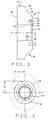
- reinforcing portion 56 has an elliptical shape and includes a circumferential dimension 72 and a longitudinal dimension 74.
- circumferential dimension 72 is equal to about 1.5 times nozzle radius R n
- longitudinal dimension 74 is equal to about 2.0 times nozzle radius R n , measured from the centerline of nozzle bore 50.
- the wall thickness of shell course 16 is chosen to permit shell course 16 to withstand the stresses and pressures exerted on RPV 10.
- Reinforcing portion 56 provides added reinforcement and strength to shell course 16 at a penetration through shell course 16.
- the thickness of reinforcing 56 is chosen so that the sum of the wall thickness of shell course 16 and the thickness of reinforcing portion 56 is about two times the wall thickness of shell course 16.
- the total thickness can be greater than or less than two times the wall thickness of shell course 16 depending on the material that shell course 16 is manufactured from and/or the expected stresses and pressures exerted on RPV 10.
- Shell course 16 is manufactured from any suitable material, for example, low alloy steel, stainless steel, and the like.
- Forged nozzle shell course 16 is fabricated by starting with a simple ring forging having an inside diameter approximately equal to the desired inside diameter of shell course 16, and having a wall thickness approximately two times the desired thickness of shell course 16. Inside surface 52 of shell course 16 is machined to the desired inside diameter of shell course 16. Outer surface 58 of shell course 16 is machined to define reinforcement portions 56. A bore 50 is machined through each reinforcement portion 56 extending from outer surface 60 of reinforcing portion 56 to inside surface 52 of shell course 16. Nozzle 36 is completed by machining groove 64 into reinforcement portion outer surface 60 so that groove 64 is coaxial with nozzle bore 50. Extension attachment surface 62 is formed by machining outer surface 60 between groove 64 and bore 50. Extension surface 62 is set back from outer surface 60 of reinforcing portion 56. The material that is machined from the simple ring forging can be recycled to minimize the costs of production.
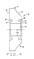
- Figure 4 is a sectional view of a forged nozzle shell course 76 in accordance with another embodiment of the present invention.
- Forged nozzle shell course 76 includes a forged nozzle 78 similar to forged nozzle 36 described above except that nozzle 76 also includes a second groove 80 machined into an inner surface 82 of forged nozzle shell course 76 and includes a second extension attachment surface 84 set back from inner surface 82 of shell course 76.
- Forged nozzle shell course 76 includes a reinforcing portion 56 having a transition section 70, a circumferential dimension 72 and a longitudinal dimension 74 (shown in Figure 3).
- Forged nozzle includes a bore 50, having a radius R nb , a groove 64 having a surface 66, and an extension attachment surface 62 set back from outer surface 60 of reinforcing portion 54.
- Figure 5 is a sectional view of a forged nozzle shell course 86 in accordance with another embodiment of the present invention.
- Forged nozzle shell course 86 includes a forged nozzle 88 that includes a groove 90 machined into an inner surface 92 of forged nozzle shell course 86 and includes an extension attachment surface 94 set back from inner surface 92 of shell course 86.
- Forged nozzle 88 includes a bore 96, having a radius R nb .
- forged nozzle shell course 86 includes a reinforcing portion 56 having a transition section 70, a circumferential dimension 72 and a longitudinal dimension 74 (shown in Figure 3).
- FIG 6 is a view of forged nozzle 36, described above, where a safe-end 98 is welded to extension attachment surface 62.
- Weld butter 100 is located on extension attachment surface 62 to facilitate welding safe end 98 to nozzle 36.
- a pipe 102 is welded to extension attachment surface 62 of forged nozzle 36.
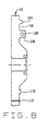
- Figure 8 is a sectional view of forged nozzle shell course 16 described above and including additional machined integral features. More specifically, forged nozzle shell course 16 includes machined integral stub 104 for attachment of a bracket to RPV 10. Integral stub 104 projects radially outward from outer surface 58 of shell course 16, and similar to reinforcement portion 54, is machined from the same ring forging as shell course 16 as described above. Forged nozzle shell course 16 also includes a machined integral bracket 106 extending radially outward from outer surface 58. Integral bracket 106 includes an opening 108 extending therethrough. Forged nozzle shell course 16 further includes machined integral track 110 for attachment of an inspection apparatus. Integral track 110 projects radially outward from outer surface 58. Integral track 104 is machined to facilitate mounting fixtures for girth weld 112 inspection.
Landscapes
- Physics & Mathematics (AREA)
- Engineering & Computer Science (AREA)
- Plasma & Fusion (AREA)
- General Engineering & Computer Science (AREA)
- High Energy & Nuclear Physics (AREA)
- Pressure Vessels And Lids Thereof (AREA)
- Monitoring And Testing Of Nuclear Reactors (AREA)
Abstract
Description
- This invention relates generally to reactor pressure vessels and more specifically to reactor pressure vessels including shell courses containing nozzles that are fabricated from a single one-piece forging.
- Boiling water nuclear reactors typically include a reactor core located within a reactor pressure vessel (RPV). A known RPV includes a substantially cylindrical shell. The shell, for example, can be about 60 feet long, about twenty feet in diameter, and about seven inches thick. Because of its length, the shell is formed from a plurality of rings or shell courses welded together. The cylindrical shell is closed at its top end by a removable top head. The top head is removable so that components located in the RPV can be accessed. The RPV cylindrical shell is closed at its bottom end by a dome shaped bottom head assembly welded to the shell.
- A plurality of nozzle openings are formed in the cylindrical shell for attachment of the pressure vessel to external pipes. Structural design standards dictate that when an opening is made in a pressure vessel, reinforcing material must be added around the opening. In addition, any weld joint used to attach nozzle reinforcing materials and connecting pipes need to be 100% volumetric inspectable.
- Known pressure vessel shell courses are made in sections from either a one-piece forging or formed and welded plate. The sections are either welded or bolted together to form the complete vessel. When the shell courses are fabricated from formed and welded plate, longitudinal weld joints are formed that have increased stress levels compared to circumferential weld joints. The nozzles are made from forgings, which are welded into bores in the cylindrical sections, or shell courses, of the pressure vessel. The nozzle forging contains the reinforcing material necessary to ensure the integrity of the nozzle, and weld preps for the nozzle-shell and nozzle-pipe weld joints.
- Periodically, known pressure boundary welds in nuclear pressure vessels are volumetrically inspected using ultrasonic testing to determine weld integrity. Accordingly, inspection equipment is required and the plant is configured to provide access for inspection.
- Known pressure vessels and processes for making pressure vessels have several disadvantages. First, the nozzle forging to shell welds must be periodically inspected. This inspection process is time consuming and utilizes large amounts of labor and financial resources. In addition, the reliability of the reactor pressure vessel depends on the integrity of the individual nozzle forging to shell welds.
- It is therefore desirable to provide a pressure vessel that includes fewer welded joints than current pressure vessels, meets all stress requirements and which eliminates vertical weld joints.
- In an exemplary embodiment, a pressure vessel for a nuclear reactor includes at least one unitary forged nozzle shell course. Unitary forged nozzle shell courses simplify the reactor pressure vessel fabrication process and reduces weld joints in the pressure vessel. The pressure vessel has a substantially cylindrical shape and includes a plurality of ring shaped shell courses welded together. At least one shell course is a forged shell course that includes at least one reinforcement portion having an enlarged thickness that extends radially outward, and a nozzle machined into the reinforcing portion of the forged shell course wall. A bore extends from an inside surface of the forged shell course to the outer end of the nozzle. The reinforcing portion and the nozzle are machined from one ring forging of sufficient thickness to form a unitary shell course that includes at least one nozzle reinforcement projecting from the outer wall. The nozzle has a radius Rn, and the nozzle bore has a radius Rnb. The reinforcement portion includes a longitudinal dimension and a circumferential dimension. The longitudinal dimension is about two times the nozzle radius Rn, and the circumferential dimension is about 1.5 times the nozzle radius Rn.
- The forged nozzle shell course is fabricated by providing a ring forging having a desired inside diameter and a thickness that is equal to a desired shell wall thickness plus at least the thickness of the reinforcing portion. The nozzle is formed in the forged nozzle shell course by machining the ring forging to form a reinforcing portion projecting radially outward from the shell wall and a nozzle machined into the reinforcing portion. The nozzle bore, having radius Rnb, is machined to be coaxial with the nozzle and to extend from the outer end of the nozzle through the shell wall to the inner surface of the shell wall.
- The above described forged nozzle shell course eliminates pressure boundary weld joints between separate nozzle forgings and the shell course and therefore, provides a reactor pressure vessel with a reduced number of weld joints that need to be inspected during service. A reduced number of welded joints improves structural integrity of the RPV. Also, the above described forged nozzle shell course simplifies the reactor pressure vessel fabrication process and eliminates the need for inspections of nozzle to shell welds.
- The invention will now be described in greater detail, by way of example, with reference to the drawings, in which:-
- Figure 1 is a schematic illustration of a reactor pressure vessel in accordance with one embodiment of the present invention.
- Figure 2 is a sectional view of a forged nozzle shell course shown in Figure 1.
- Figure 3 is a front view of the forged nozzle shown in Figure 2.
- Figure 4 is a sectional view of a forged nozzle shell course shown in Figure 1 in accordance with another embodiment of the present invention.
- Figure 5 is a sectional view of a forged nozzle shell course shown in Figure 1 in accordance with another embodiment of the present invention.
- Figures 6 is a sectional view of the forged nozzle shown in Figure 2 with a safe-end attached.
- Figure 7 is a sectional view of the forged nozzle shown in Figure 2 with a pipe attached.
- Figure 8 is a schematic illustration of a forged nozzle shell course with machined integral features in accordance with an embodiment of the present invention.
-
- Figure 1 is a schematic illustration of a reactor pressure vessel (RPV) 10. RPV 10 includes a
top head 12, four substantiallycylindrical shell courses bottom head assembly 22. In accordance with an exemplary embodiment of the present invention,shell course 16 is a unitary forgednozzle shell course 16.Top head 12 includes ahead flange 24.First shell course 14 includes avessel flange 26.Top head 12 is bolted toshell course 14 bybolts 28, which extend throughhead flange 24.Top head 12 also includeslifting flanges 30 to lifttop head 12 fromfirst shell course 14. -
First shell course 14 includesmain steam nozzles 32 through which stem flows out of theRPV 10.Stabilizer brackets 34 also are formed onfirst shell course 14. Forgednozzle shell course 16 includes a plurality of forgednozzles 36 formed therein. Forgednozzle shell course 16 and forgednozzles 36 are machined from one forging to form a unitary forgednozzle shell course 16.Fourth shell course 20 includes asupport skirt 42 welded thereto.Support skirt 42 supportsRPV 10 within the reactor building (not shown). - Figure 2 is a cross-sectional view of a portion of forged
nozzle shell course 16 with forgednozzle 36. Forgednozzle 36 is unitary with forgednozzle shell course 16. Forgednozzle 36 is machined from the mass ofshell course 16. Becauseshell course 16 and forgednozzle 36 are machined from one forging, the number of welds inRPV 10 are reduced. This has the advantage of reducing the number of welds subject to service inspections and more simplified fabrication ofRPV 10. -
Nozzle 36 includes abore 50 extending from aninside surface 52 ofshell course 16 to anouter end 54 ofnozzle 36.Shell course 16 includes a reinforcingportion 56 extending from anouter surface 58 ofshell course 16.Nozzle 36 is machined into reinforcingportion 56 such thatouter end 54 ofnozzle 36 does not extend past anouter surface 60 of reinforcingportion 56. In other words, nozzleouter end 54 is set back fromouter surface 60 of reinforcingportion 56.Outer end 54 ofnozzle 36 defines a safe end orextension attachment surface 62. Agroove 64 machined into reinforcingportion 56 is coaxial with nozzle bore 50.Groove 64 permits access tonozzle 36outer end 54 for welding an extension or safe end (not shown in Figure 2) toattachment surface 62. The distance from the centerline ofbore 50 to asurface 66 ofgroove 64 is defined as a radius Rn ofnozzle 36. The distance from the centerline ofbore 50 to aninner surface 68 ofbore 50 is defined as a radius Rnb of nozzle bore 50. - Reinforcing
portion 56 includes atransition section 70 which tapers fromouter surface 60 of reinforcingportion 56 toouter surface 58 ofshell course 16. Referring to Figure 3, reinforcingportion 56 has an elliptical shape and includes acircumferential dimension 72 and alongitudinal dimension 74. In an exemplary embodimentcircumferential dimension 72 is equal to about 1.5 times nozzle radius Rn, andlongitudinal dimension 74 is equal to about 2.0 times nozzle radius Rn, measured from the centerline of nozzle bore 50. - Referring to Figure 2, the wall thickness of
shell course 16 is chosen to permitshell course 16 to withstand the stresses and pressures exerted onRPV 10. Reinforcingportion 56 provides added reinforcement and strength toshell course 16 at a penetration throughshell course 16. In one embodiment, the thickness of reinforcing 56 is chosen so that the sum of the wall thickness ofshell course 16 and the thickness of reinforcingportion 56 is about two times the wall thickness ofshell course 16. In other embodiments the total thickness can be greater than or less than two times the wall thickness ofshell course 16 depending on the material that shellcourse 16 is manufactured from and/or the expected stresses and pressures exerted onRPV 10.Shell course 16 is manufactured from any suitable material, for example, low alloy steel, stainless steel, and the like. - Forged
nozzle shell course 16 is fabricated by starting with a simple ring forging having an inside diameter approximately equal to the desired inside diameter ofshell course 16, and having a wall thickness approximately two times the desired thickness ofshell course 16. Insidesurface 52 ofshell course 16 is machined to the desired inside diameter ofshell course 16.Outer surface 58 ofshell course 16 is machined to definereinforcement portions 56. A bore 50 is machined through eachreinforcement portion 56 extending fromouter surface 60 of reinforcingportion 56 toinside surface 52 ofshell course 16.Nozzle 36 is completed by machininggroove 64 into reinforcement portionouter surface 60 so thatgroove 64 is coaxial with nozzle bore 50.Extension attachment surface 62 is formed by machiningouter surface 60 betweengroove 64 and bore 50.Extension surface 62 is set back fromouter surface 60 of reinforcingportion 56. The material that is machined from the simple ring forging can be recycled to minimize the costs of production. - Figure 4 is a sectional view of a forged
nozzle shell course 76 in accordance with another embodiment of the present invention. Forgednozzle shell course 76 includes a forgednozzle 78 similar to forgednozzle 36 described above except thatnozzle 76 also includes asecond groove 80 machined into aninner surface 82 of forgednozzle shell course 76 and includes a secondextension attachment surface 84 set back frominner surface 82 ofshell course 76. As described above, Forgednozzle shell course 76 includes a reinforcingportion 56 having atransition section 70, acircumferential dimension 72 and a longitudinal dimension 74 (shown in Figure 3). Forged nozzle includes abore 50, having a radius Rnb, agroove 64 having asurface 66, and anextension attachment surface 62 set back fromouter surface 60 of reinforcingportion 54. - Figure 5 is a sectional view of a forged
nozzle shell course 86 in accordance with another embodiment of the present invention. Forgednozzle shell course 86 includes a forgednozzle 88 that includes agroove 90 machined into aninner surface 92 of forgednozzle shell course 86 and includes anextension attachment surface 94 set back frominner surface 92 ofshell course 86. Forgednozzle 88 includes abore 96, having a radius Rnb. As described above, forgednozzle shell course 86 includes a reinforcingportion 56 having atransition section 70, acircumferential dimension 72 and a longitudinal dimension 74 (shown in Figure 3). - Figure 6 is a view of forged
nozzle 36, described above, where a safe-end 98 is welded toextension attachment surface 62.Weld butter 100 is located onextension attachment surface 62 to facilitate weldingsafe end 98 tonozzle 36. In an alternative embodiment, shown in Figure 7, apipe 102 is welded toextension attachment surface 62 of forgednozzle 36. These weld joints are not part of the pressure boundary ofshell course 16 and therefore are not necessary to resist the hoop and axial stresses inshell course 16. These weld joints are part of the attachment pressure boundary and need to resist the hoop and axial stresses in the attachment,safe end 98 orpipe 102. - Figure 8 is a sectional view of forged
nozzle shell course 16 described above and including additional machined integral features. More specifically, forgednozzle shell course 16 includes machinedintegral stub 104 for attachment of a bracket toRPV 10.Integral stub 104 projects radially outward fromouter surface 58 ofshell course 16, and similar toreinforcement portion 54, is machined from the same ring forging asshell course 16 as described above. Forgednozzle shell course 16 also includes a machinedintegral bracket 106 extending radially outward fromouter surface 58.Integral bracket 106 includes anopening 108 extending therethrough. Forgednozzle shell course 16 further includes machinedintegral track 110 for attachment of an inspection apparatus.Integral track 110 projects radially outward fromouter surface 58.Integral track 104 is machined to facilitate mounting fixtures forgirth weld 112 inspection. - For the sake of good order, various aspects of the invention are set out in the following clauses:-
- 1. A forged nozzle shell course for a pressure vessel, said shell course
comprising at least one reinforcement portion extending radially outward from
an outer surface of said shell course, each said reinforcing portion comprising
a nozzle having a radius, said nozzle comprising:
- a bore extending from an outside surface of said reinforcing portion to an inside surface of said shell course; and
- at least one extension attachment surface located adjacent to and coaxial to said bore, said reinforcing portion comprising a longitudinal dimension equal to about 2.0 times said radius of said nozzle, and a circumferential dimension equal to about 1.5 times the radius of said nozzle, measured from the centerline of said nozzle bore.
- 2. A forged nozzle shell course according to Clause 1 further comprising an integral groove extending into an outer end of said nozzle, said groove coaxial with said nozzle bore and located adjacent an extension attachment surface.
- 3. A forged nozzle shell course according to Clause 1 further comprising an integral groove extending into said inner surface of said shell course said groove coaxial with said nozzle bore and located adjacent an extension attachment surface.
- 4. A forged nozzle shell course according to Clause 2 further comprising an integral groove extending into said inner surface of said shell course said groove coaxial with said nozzle bore and located adjacent an extension attachment surface.
- 5. A forged nozzle shell course according to Clause 1 further comprising an integral stub projecting radially outward from said outer surface of said shell course for attaching a bracket.
- 6. A forged nozzle shell course according to Clause 1 further comprising an integral bracket projecting radially outward from said outer surface of said shell course
- 7. A forged nozzle shell course according to Clause 1 further comprising an integral track stub projecting radially outward from said outer surface of said shell course for attaching an inspection apparatus to said shell course.
- 8. A forged nozzle shell course according to Clause 1, further comprising an extension sleeve welded to an extension attachment surface.
- 9. A forged nozzle shell course according to Clause 1, further comprising at least one of a safe end and a pipe welded to the forged nozzle.
- 10. A pressure vessel comprising:
a plurality of forged shell courses wherein at least one forged shell course comprises at least one reinforcement portion extending radially outward from an outer surface of said shell course, each said reinforcing portion comprising a nozzle having a radius, said nozzle comprising: - a bore extending from an outside surface of said reinforcing portion to an inside surface of said shell course; and
- at least one extension attachment surface located adjacent to and coaxial to said bore, said reinforcing portion comprising a longitudinal dimension equal to about 2.0 times the radius of said nozzle, and a circumferential dimension equal to about 1.5 times the radius of said nozzle, measured from the centerline of said nozzle bore;
- a top head coupled to a first forged shell course; and
- a bottom head assembly coupled to a last shell course.
- 11. A pressure vessel according to
Clause 10 wherein said at least one forged shell course further comprises an integral groove extending into an outer end of said nozzle, said groove coaxial with said nozzle bore and located adjacent an extension attachment surface. - 12. A pressure vessel according to Clause 11 wherein said at least one forged shell course further comprises an integral groove extending into said inner surface of said at least one forged shell course said groove coaxial with said nozzle bore and located adjacent an extension attachment surface.
- 13. A pressure vessel according to
Clause 10 wherein said at least one forged shell course further comprises an integral groove extending into said inner surface of said at least one forged shell course said groove coaxial with said nozzle bore and located adjacent an extension attachment surface. - 14. A pressure vessel according to
Clause 10 wherein said at least one forged shell course further comprises an integral track projecting radially outward from an outer portion of a shell wall of said shell course for attaching an inspection apparatus to said shell course. - 15. A pressure vessel according to
Clause 10 wherein said at least one forged shell course further comprises an integral bracket projecting radially outward from an outer portion of a shell wall of said shell course. - 16. A pressure vessel according to
Clause 10 wherein said at least one forged shell course further comprises at least one of a safe end and a pipe welded to said forged nozzle. - 17. A method of fabricating a forged nozzle shell course, said method
comprising the steps of:
- providing a ring forging having a desired inside diameter;
- machining the ring forging to form a radially outward projecting reinforcement portion including a nozzle having a radius;
- machining a nozzle bore extending from an outer surface of the reinforcement portion to an inner surface of the ring forging; and
- machining at least one extension attachment surface located adjacent to and coaxial to the nozzle bore, the reinforcing portion comprising a longitudinal dimension equal to about 2.0 times the radius of the nozzle, and a circumferential dimension equal to about 1.5 times the radius of the nozzle, measured from the nozzle bore center line.
- 18. A method according to Clause 17 further comprising the step of machining an integral groove extending into an outer end of the nozzle, the groove coaxial with the nozzle bore and located adjacent an extension attachment surface
- 19. A method according to
Clause 18 further comprising the step of machining an integral groove extending into the inner surface of the forged shell course the groove coaxial with the nozzle bore and located adjacent an extension attachment surface. - 20. A method according to Clause 17 further comprising the step of machining an integral groove extending into the inner surface of the forged shell course the groove coaxial with the nozzle bore and located adjacent an extension attachment surface.
- 21. A method according to Clause 17 further comprising the step of machining an integral track to an surface of the ring forging for attaching an inspection apparatus to the shell course.
- 22. A method according to Clause 17 further comprising the step of locating weld butter on at least one extension attachment surface.
- 23. A method according to
Clause 22 further comprising the step of welding at least one of a safe end and a pipe to the at least one extension attachment surface. -
Claims (10)
- A forged nozzle shell course (16) for a pressure vessel (10), said shell course comprising at least one reinforcement portion (56) extending radially outward from an outer surface (58) of said shell course, each said reinforcing portion comprising a nozzle (36) having a radius, said nozzle comprising:a bore (50) extending from an outside surface of said reinforcing portion to an inside surface (52) of said shell course; andat least one extension attachment surface (62) located adjacent to and coaxial to said bore, said reinforcing portion comprising a longitudinal dimension (74) equal to about 2.0 times said radius of said nozzle, and a circumferential dimension (72) equal to about 1.5 times the radius of said nozzle, measured from the centerline of said nozzle bore.
- A forged nozzle shell course (16) according to Claim 1 further comprising an integral groove (64) extending into an outer end (54) of said nozzle (36), said groove coaxial with said nozzle bore (50) and located adjacent an extension attachment surface (62).
- A forged nozzle shell course (16) according to Claim 1 or 2 further comprising an integral groove (64) extending into said inner surface (52) of said shell course said groove coaxial with said nozzle bore (50) and located adjacent an extension attachment surface (62).
- A forged nozzle shell course (16) according to Claim 1, 2 or 3 further comprising an integral stub (104) projecting radially outward from said outer surface (58) of said shell course for attaching a bracket (106).
- A pressure vessel (10) comprising:
a plurality of forged shell courses (14, 16, 18, 20) wherein at least one forged shell course comprises at least one reinforcement portion (56) extending radially outward from an outer surface (58) of said shell course, each said reinforcing portion comprising a nozzle (36) having a radius, said nozzle comprising:a bore (50) extending from an outside surface (60) of said reinforcing portion to an inside surface (52) of said shell course; andat least one extension attachment surface (62) located adjacent to and coaxial to said bore, said reinforcing portion comprising a longitudinal dimension (74) equal to about 2.0 times the radius of said nozzle, and a circumferential dimension (72) equal to about 1.5 times the radius of said nozzle, measured from the centerline of said nozzle bore;a top head (12) coupled to a first forged shell course (14); anda bottom head assembly (22) coupled to a last shell course (20). - A pressure vessel (10) according to Claim 5 wherein said at least one forged shell course (16) further comprises an integral groove (64) extending into an outer end (54) of said nozzle, said groove coaxial with said nozzle bore (50) and located adjacent an extension attachment surface (62).
- A pressure vessel (10) according to Claim 6 wherein said at least one forged shell course (16) further comprises an integral groove (64) extending into said inner surface (52) of said at least one forged shell course said groove coaxial with said nozzle bore (50) and located adjacent an extension attachment surface (62).
- A method of fabricating a forged nozzle shell course (16), said method comprising the steps of:providing a ring forging having a desired inside diameter;machining the ring forging to form a radially outward projecting reinforcement portion (56) including a nozzle (36) having a radius;machining a nozzle bore (50) extending from an outer surface (60) of the reinforcement portion to an inner surface (52) of the ring forging; andmachining at least one extension attachment surface (62) located adjacent to and coaxial to the nozzle bore, the reinforcing portion comprising a longitudinal dimension (74) equal to about 2.0 times the radius of the nozzle, and a circumferential dimension (72) equal to about 1.5 times the radius of the nozzle, measured from the nozzle bore center line.
- A method according to Claim 8 further comprising the step of machining an integral groove (64) extending into an outer end (54) of the nozzle (36), the groove coaxial with the nozzle bore (50) and located adjacent an extension attachment surface (62).
- A method according to Claim 9 further comprising the step of machining an integral groove (64) extending into the inner surface (52) of the forged shell course (16) the groove coaxial with the nozzle bore (50) and located adjacent an extension attachment surface (62).
Applications Claiming Priority (2)
| Application Number | Priority Date | Filing Date | Title |
|---|---|---|---|
| US09/644,378 US6426986B1 (en) | 2000-08-23 | 2000-08-23 | Forged nozzle shell course for a pressure vessel |
| US644378 | 2000-08-23 |
Publications (1)
| Publication Number | Publication Date |
|---|---|
| EP1182670A1 true EP1182670A1 (en) | 2002-02-27 |
Family
ID=24584651
Family Applications (1)
| Application Number | Title | Priority Date | Filing Date |
|---|---|---|---|
| EP01306674A Ceased EP1182670A1 (en) | 2000-08-23 | 2001-08-03 | Forged nozzle shell course for a pressure vessel |
Country Status (4)
| Country | Link |
|---|---|
| US (1) | US6426986B1 (en) |
| EP (1) | EP1182670A1 (en) |
| JP (1) | JP4837201B2 (en) |
| CN (1) | CN1339344A (en) |
Cited By (1)
| Publication number | Priority date | Publication date | Assignee | Title |
|---|---|---|---|---|
| DE102008013575B3 (en) * | 2008-03-11 | 2009-08-13 | Poppe & Potthoff Gmbh | Fuel rail assembly |
Families Citing this family (6)
| Publication number | Priority date | Publication date | Assignee | Title |
|---|---|---|---|---|
| US6888908B1 (en) * | 2002-11-18 | 2005-05-03 | Babcock & Wilcox Canada, Ltd. | Reactor head with integral nozzles |
| KR101108494B1 (en) | 2010-03-26 | 2012-01-31 | 문준식 | How to attach lining of nozzle for pressure vessel |
| CN102345737A (en) * | 2010-07-28 | 2012-02-08 | 清华大学 | Nozzle of pressure vessel |
| CN101916597B (en) * | 2010-08-19 | 2012-08-22 | 中广核检测技术有限公司 | Automatic detection device and positioning method for weld joint at safe end of nuclear reactor pressure vessel |
| JP5241794B2 (en) * | 2010-10-15 | 2013-07-17 | 株式会社神戸製鋼所 | Pressure vessel |
| AU2015337799B2 (en) * | 2014-10-28 | 2018-02-01 | Maxheat Hot Water Pty Ltd | Hot water storage device |
Citations (6)
| Publication number | Priority date | Publication date | Assignee | Title |
|---|---|---|---|---|
| FR2317568A1 (en) * | 1975-07-08 | 1977-02-04 | Cockerill | METAL CONTAINER WITH VERY THICKNESS WALLS, ESPECIALLY NUCLEAR REACTOR TANK |
| JPS62114743A (en) * | 1985-11-12 | 1987-05-26 | Kawasaki Steel Corp | One-body forming method for nozzle |
| EP0312421A1 (en) * | 1987-10-16 | 1989-04-19 | Framatome | Method of fixing by welding a nozzle to a thick-walled element such as a nozzle belt of a nuclear reactor vessel |
| EP0681301A1 (en) * | 1994-05-04 | 1995-11-08 | General Electric Company | Feedwater nozzle and method of repair |
| US5721758A (en) * | 1996-02-29 | 1998-02-24 | General Electric Company | Bottom head to shell junction assembly for a boiling water nuclear reactor |
| JPH11148993A (en) * | 1997-08-29 | 1999-06-02 | General Electric Co <Ge> | Lower head for boiling water reactor |
Family Cites Families (19)
| Publication number | Priority date | Publication date | Assignee | Title |
|---|---|---|---|---|
| GB854946A (en) * | 1957-05-28 | 1960-11-23 | Babcock & Wilcox Ltd | Improvements in removable closure members for pressure vessels and to a method of manufacture thereof |
| US3744660A (en) * | 1970-12-30 | 1973-07-10 | Combustion Eng | Shield for nuclear reactor vessel |
| JPS5224314A (en) * | 1975-08-20 | 1977-02-23 | Babcock Hitachi Kk | An attachment fixing structure to a pressure device |
| DE2808104C3 (en) * | 1978-02-24 | 1981-01-15 | Kraftwerk Union Ag, 4330 Muelheim | Atomic nuclear reactor with a cylindrical reactor pressure vessel |
| JPS5561951A (en) * | 1978-11-06 | 1980-05-10 | Hitachi Ltd | Nozzle structure |
| DE3135330A1 (en) * | 1981-09-05 | 1983-03-24 | Basf Ag, 6700 Ludwigshafen | DYES WITH ISOCHINOLINE CLUTCH COMPONENTS |
| JPS58142294A (en) * | 1982-02-17 | 1983-08-24 | 株式会社東芝 | Reactor pressure vessel |
| JPS59122598A (en) * | 1982-12-28 | 1984-07-16 | Toagosei Chem Ind Co Ltd | Metallic screw element |
| JPS62146992A (en) * | 1985-12-21 | 1987-06-30 | Kansai Coke & Chem Co Ltd | Production of highly calorific gas |
| JPH0750192B2 (en) * | 1986-07-18 | 1995-05-31 | 株式会社東芝 | Recirculation outlet nozzle annular space water injection device |
| JPS63255698A (en) * | 1987-04-13 | 1988-10-21 | 株式会社東芝 | Nozzle inner-surface fluid injector |
| US4767593A (en) * | 1987-06-15 | 1988-08-30 | Wedellsborg Bendt W | Multiple shell pressure vessel |
| FR2622041B1 (en) * | 1987-10-16 | 1990-03-09 | Framatome Sa | METHOD FOR MANUFACTURING A VESSEL OF A LIGHT WATER NUCLEAR REACTOR AND VESSEL OF A NUCLEAR REACTOR MANUFACTURED BY THIS PROCESS |
| US5217681A (en) * | 1991-06-14 | 1993-06-08 | Wedellsborg Bendt W | Special enclosure for a pressure vessel |
| DE4308207A1 (en) * | 1993-03-15 | 1994-09-22 | Siemens Ag | Reactor pressure vessel with limited failure zones |
| US5353320A (en) * | 1993-04-05 | 1994-10-04 | General Electric Company | Reactor pressure vessel nozzle |
| JPH0755987A (en) * | 1993-08-20 | 1995-03-03 | Hitachi Ltd | In-core inspection and repair device for nuclear reactor |
| US5465280A (en) * | 1994-06-08 | 1995-11-07 | Wedellsborg; Bendt W. | Pressure vessel apparatus |
| US5930320A (en) * | 1997-05-01 | 1999-07-27 | General Electric Company | Assemblies and methods for mitigating effects of reactor pressure vessel expansion |
-
2000
- 2000-08-23 US US09/644,378 patent/US6426986B1/en not_active Expired - Lifetime
-
2001
- 2001-08-03 EP EP01306674A patent/EP1182670A1/en not_active Ceased
- 2001-08-21 JP JP2001249754A patent/JP4837201B2/en not_active Expired - Lifetime
- 2001-08-23 CN CN01125757A patent/CN1339344A/en active Pending
Patent Citations (7)
| Publication number | Priority date | Publication date | Assignee | Title |
|---|---|---|---|---|
| FR2317568A1 (en) * | 1975-07-08 | 1977-02-04 | Cockerill | METAL CONTAINER WITH VERY THICKNESS WALLS, ESPECIALLY NUCLEAR REACTOR TANK |
| JPS62114743A (en) * | 1985-11-12 | 1987-05-26 | Kawasaki Steel Corp | One-body forming method for nozzle |
| EP0312421A1 (en) * | 1987-10-16 | 1989-04-19 | Framatome | Method of fixing by welding a nozzle to a thick-walled element such as a nozzle belt of a nuclear reactor vessel |
| EP0681301A1 (en) * | 1994-05-04 | 1995-11-08 | General Electric Company | Feedwater nozzle and method of repair |
| US5721758A (en) * | 1996-02-29 | 1998-02-24 | General Electric Company | Bottom head to shell junction assembly for a boiling water nuclear reactor |
| JPH11148993A (en) * | 1997-08-29 | 1999-06-02 | General Electric Co <Ge> | Lower head for boiling water reactor |
| US6188741B1 (en) * | 1997-08-29 | 2001-02-13 | General Electric Company | Machined stub tube in a bottom head of a boiling water reactor |
Non-Patent Citations (2)
| Title |
|---|
| PATENT ABSTRACTS OF JAPAN vol. 011, no. 333 (M - 637) 30 October 1987 (1987-10-30) * |
| PATENT ABSTRACTS OF JAPAN vol. 1999, no. 11 30 September 1999 (1999-09-30) * |
Cited By (3)
| Publication number | Priority date | Publication date | Assignee | Title |
|---|---|---|---|---|
| DE102008013575B3 (en) * | 2008-03-11 | 2009-08-13 | Poppe & Potthoff Gmbh | Fuel rail assembly |
| WO2009112191A1 (en) | 2008-03-11 | 2009-09-17 | Poppe & Potthoff Gmbh | Fuel distributor assembly |
| US8419073B2 (en) | 2008-03-11 | 2013-04-16 | Poppe & Potthoff Gmbh | Fuel distributor assembly |
Also Published As
| Publication number | Publication date |
|---|---|
| US6426986B1 (en) | 2002-07-30 |
| JP4837201B2 (en) | 2011-12-14 |
| CN1339344A (en) | 2002-03-13 |
| JP2002174691A (en) | 2002-06-21 |
Similar Documents
| Publication | Publication Date | Title |
|---|---|---|
| US6163588A (en) | Core plate and reactor internal pump differential pressure lines for a boiling water reactor | |
| JPS6349752Y2 (en) | ||
| US6426986B1 (en) | Forged nozzle shell course for a pressure vessel | |
| US4724975A (en) | High-pressure structure made of rings with peripheral weldments of reduced thickness | |
| US5809098A (en) | Method for sealing a stub tube in a nuclear reactor | |
| US5737378A (en) | Reactor shroud joint | |
| US6188741B1 (en) | Machined stub tube in a bottom head of a boiling water reactor | |
| US4948938A (en) | Process for fastening a pipe by welding to a thick wall member such as a pipe-carrying shell of a nuclear reactor vessel | |
| US6091791A (en) | Shroud attachment for a boiling water reactor | |
| US5796797A (en) | Method for sealing a stub tube in a nuclear reactor | |
| US6389094B1 (en) | Integral forged shroud flange for a boiling water reactor | |
| EP0805462B1 (en) | Pressure vessel bottom penetration assembly | |
| WO2025025964A1 (en) | Universal pump casing for nuclear power main pump | |
| US5721758A (en) | Bottom head to shell junction assembly for a boiling water nuclear reactor | |
| FI118105B (en) | Mantel weld joint for a boiler reactor | |
| US6435825B1 (en) | Hollow nozzle partition with optimized wall thickness and method of forming | |
| US4638768A (en) | Steam generator tubesheet/channel head/centerstay assembly | |
| US3587905A (en) | Pressure vessel | |
| US4570813A (en) | Connection anchor for liner of cast iron pressure tank | |
| Zheng | Design philosophy of flat ribbon wound layered pressure vessel | |
| JP3887759B2 (en) | Core support structure | |
| JP2004085311A (en) | Nozzle to be attached to cylindrical object, and reactor pressure vessel equipped with the nozzle | |
| US6563900B2 (en) | Ring plate around openings in reinforced concrete containment vessel | |
| JP2675545B2 (en) | Reactor containment vessel having vent pipe and method for assembling the same | |
| JPS6341039B2 (en) |
Legal Events
| Date | Code | Title | Description |
|---|---|---|---|
| PUAI | Public reference made under article 153(3) epc to a published international application that has entered the european phase |
Free format text: ORIGINAL CODE: 0009012 |
|
| AK | Designated contracting states |
Kind code of ref document: A1 Designated state(s): DE ES FI IT NL SE Kind code of ref document: A1 Designated state(s): AT BE CH CY DE DK ES FI FR GB GR IE IT LI LU MC NL PT SE TR |
|
| AX | Request for extension of the european patent |
Free format text: AL;LT;LV;MK;RO;SI |
|
| 17P | Request for examination filed |
Effective date: 20020827 |
|
| AKX | Designation fees paid |
Free format text: DE ES FI IT NL SE |
|
| STAA | Information on the status of an ep patent application or granted ep patent |
Free format text: STATUS: THE APPLICATION HAS BEEN REFUSED |
|
| 18R | Application refused |
Effective date: 20080705 |