EP1182483A2 - Apparatus for fabricating optical backplanes - Google Patents
Apparatus for fabricating optical backplanes Download PDFInfo
- Publication number
- EP1182483A2 EP1182483A2 EP01120130A EP01120130A EP1182483A2 EP 1182483 A2 EP1182483 A2 EP 1182483A2 EP 01120130 A EP01120130 A EP 01120130A EP 01120130 A EP01120130 A EP 01120130A EP 1182483 A2 EP1182483 A2 EP 1182483A2
- Authority
- EP
- European Patent Office
- Prior art keywords
- substrate
- optical fiber
- fiber
- drive rollers
- routing
- Prior art date
- Legal status (The legal status is an assumption and is not a legal conclusion. Google has not performed a legal analysis and makes no representation as to the accuracy of the status listed.)
- Granted
Links
Images


Classifications
-
- G—PHYSICS
- G02—OPTICS
- G02B—OPTICAL ELEMENTS, SYSTEMS OR APPARATUS
- G02B6/00—Light guides; Structural details of arrangements comprising light guides and other optical elements, e.g. couplings
- G02B6/24—Coupling light guides
- G02B6/36—Mechanical coupling means
- G02B6/3608—Fibre wiring boards, i.e. where fibres are embedded or attached in a pattern on or to a substrate, e.g. flexible sheets
- G02B6/3612—Wiring methods or machines
-
- G—PHYSICS
- G02—OPTICS
- G02B—OPTICAL ELEMENTS, SYSTEMS OR APPARATUS
- G02B6/00—Light guides; Structural details of arrangements comprising light guides and other optical elements, e.g. couplings
- G02B6/24—Coupling light guides
- G02B6/26—Optical coupling means
- G02B6/28—Optical coupling means having data bus means, i.e. plural waveguides interconnected and providing an inherently bidirectional system by mixing and splitting signals
-
- G—PHYSICS
- G02—OPTICS
- G02B—OPTICAL ELEMENTS, SYSTEMS OR APPARATUS
- G02B6/00—Light guides; Structural details of arrangements comprising light guides and other optical elements, e.g. couplings
- G02B6/24—Coupling light guides
- G02B6/42—Coupling light guides with opto-electronic elements
- G02B6/43—Arrangements comprising a plurality of opto-electronic elements and associated optical interconnections
Definitions
- This invention generally relates to the art of fiber optic transmissions and interconnections and, particularly, to optical backplanes.
- Optical backplanes are increasingly being used in electronics systems where circuit density is ever-increasing and is difficult to provide with known electrically wired backplanes.
- An optical backplane is formed by a plurality of optical fibers mounted or routed on a substrate in a given pattern or circuit geometry.
- Optical backplanes are used to interconnect optical circuit components which transmit signals optically, as well as electrical circuit components, wiring boards, modules and/or integrated circuits.
- an optical backplane interconnects electrical components, the electrical energy of each component is translated to optical energy which is transmitted by optical fibers on the optical backplane to another electrical component where it is translated back to electrical energy for transmission to the other electrical component.
- Optical fibers can transmit much more information than electrical conductors and with significantly less signal degradation.
- Optical backplanes are fabricated in a variety of manners, ranging from laying the optical fibers on the substrate by hand to routing the optical fibers in a given pattern onto the substrate by mechanized apparatus. Most such apparatus are complex and expensive to manufacture and are difficult to maintain.
- the present invention is directed to providing a simple, efficient and reliable apparatus for use in fabricating optical backplanes.
- An object, therefore, of the invention is to provide a new and improved apparatus for routing an optical fiber from a supply thereof onto a surface of a substrate which may have an adhesive thereon.
- the apparatus includes a routing head which is movable over the surface of the substrate in a given circuit pattern.
- Drive means is provided for feeding the optical fiber from the supply to the routing head.
- a feed needle on the routing head receives the optical fiber from the drive means and lays the fiber onto the surface of the substrate at an angle thereto as the routing head moves thereover. The inherent stiffness of the angled optical fiber biases the fiber against the adhesive on the surface of the substrate as the fiber is layed onto the surface in the given circuit pattern.
- the supply of optical fiber comprises a rotatable reel upon which the optical fiber is wound and off of which the fiber is pulled by the drive means.
- the feed needle extends at an angle to the surface of the substrate and terminates in a distal end extending generally parallel to the substrate.
- the distal end has an open channel on the outside thereof facing the surface of the substrate and through which the optical fiber is fed to the surface.
- the drive means is provided by a pair of drive rollers sandwiching the optical fiber therebetween.
- Second drive rollers are provided nearer to the feed needle than the pair of drive rollers and establish a fiber loop therebetween.
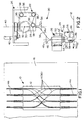
- the optical backplane is typical and includes a flat substrate 12 having a plurality of optical fibers 14 routed thereon in a given circuit pattern.
- the ends 14a of the optical fibers extend beyond substrate 12 for connection to a wide variety of components, such as optical transmission components as well as electrical transmission components ranging from wiring boards to circuit modules and/or integrated circuits.
- Optical backplane 10, including substrate 12 and optical fibers 14, are fabricated on top of an enlarged release sheet 16. Before optical fibers 14 are laid onto substrate 12, the substrate and release sheet 16 are coated with an adhesive. Therefore, optical fibers 14 will adhere to substrate 12 and fiber ends 14a will adhere to release sheet 16. The release sheet is removed after fabrication and the substrate and fibers are coated with a non-adhesive material.
- FIGS 2-4 show somewhat schematically an apparatus, generally designated 20, for fabricating optical backplanes, such as backplane 10, by routing optical fibers 14 onto the surface of substrate 12 (as well as release sheet 16).
- apparatus 20 includes a supply head, generally designated 22, and a routing head, generally designated 24.
- the apparatus is mounted on an overall framework, generally designated 26, only a top portion of which is shown in the drawings.
- supply head 22 includes a mounting block 28 on which a supply reel 30 is mounted for rotation about an axis 32 and is rotated by a motor (not shown) at a speed which is synchronized with the speed at which the fiber 14 is layed on the substrate 12.
- a distribution horn 34 depends from mounting block 28 and has a flared open end 34a.
- An optical fiber 36 is pulled off of supply reel 30, around a series of pulleys 38 and downwardly through distribution horn 34.
- the pulleys 38 create a compensation loop of fiber 36 which allows routing head 24 to move when no fiber laying is taking place.
- the entire mounting block, including supply reel 30, distribution horn 34 and pulleys 38, is rotatable about a vertical axis 40 by means of a motor 42 and a belt 44, the motor being mounted on framework 26.
- routing head 24 includes an upwardly directed receiving horn 46 having a flared mouth 46a for receiving optical fiber 36 from distribution horn 34 of supply head 22.
- Routing head 24 is rotatable about a vertical axis 48 by means of a motor 50 and a belt 52.
- Supply head 22 and routing head 24 are rotated in synchronization so that optical fiber 36 does not twist therebetween.
- a lifting motor 54 is provided for moving routing head 24 vertically, i.e., generally perpendicular to substrate 12.
- a first pair of drive rollers 56 sandwich optical fiber 36 therebetween and pull the optical fiber from supply head 22 off of pulleys 30.
- a second pair of drive rollers 58 are provided down-line of drive rollers 56 to form a fiber loop 60 therebetween.
- the surfaces of the drive rollers may be of a fiber-gripping material such as rubber.
- optical fiber 36 is fed to a feed needle 62 which lays the optical fiber onto the top surface of substrate 12 (and release sheet 16) which has the adhesive layer thereon.
- optical fiber 36 is fed from drive rollers 58 through a cutoff mechanism 64 to feed needle 62 which has an internal passage 66. Although a top portion 66a of the passage is oriented vertically to receive optical fiber 36 from eye 64, the needle and passage are at approximately a 45 ° angle 68 relative to substrate 12 as the needle lays optical fiber 36 onto the substrate in the direction of arrow 70.
- passage 66 (Fig. 5) actually is formed within a needle tube 72 embedded within needle 62.
- the needle tube has a distal end 74 which curves to an orientation generally parallel to substrate 12.
- the bottom of distal end 74 is provided with an open channel 76 as best seen in Figure 6, the channel being on the outside of the distal end facing the surface of substrate 12.
- the distal end is recessed, as at 78, to avoid any possible interference with previously laid optical fibers 36a.
- optical fiber 36 is laid onto the surface of substrate 12 at an angle 68.
- optical fibers are generally brittle and rather stiff. Consequently, as the angled or bent optical fiber is laid onto the substrate as routing head 24 moves in the direction of arrow 70 (Figs. 2, 4 and 5), a vertical force vector is created by the stiffness of the bent optical fiber to bias the optical fiber against the adhesive on the surface of substrate 12.
- Drive rollers 56 are synchronized with the speed of routing head 24 translating over the substrate so that the drive rollers feed optical fiber 36 to feed needle 62 at the same speed that the routing head moves over the substrate.
- second drive rollers 58 are used only at the start of laying a length of optical fiber onto the substrate, such as the beginning of one of the fiber ends 14a shown in Figure 1. These second drive rollers are rotated slightly faster than the speed with which routing head 24 moves over the substrate to add an increment of force to the optical fiber to facilitate forcing the fiber against the adhesive on the substrate (actually release sheet 16). That is why a supply buffer loop 60 of the optical fiber is maintained between first drive rollers 56 and second drive rollers 58. After a short initial increment of travel of routing head 24, second drive rollers 58 are moved apart to release the feeding pressure on the optical fiber. This allows the fiber to be freely pulled off the supply buffer loop 60 and are allowed to freely rotate.
- a length of optical fiber 14 (Fig. 1) has been layed onto substrate 12 and release sheet 16
- the fiber is cut, routing head 24 is lifted, and another optical fiber length or circuit is layed down in a given circuit pattern, such as the pattern shown in Figure 1.
- All of the operative motions of apparatus 20, including the translation of routing head 24, the rotation or pivoting of the routing head and supply head 26, the lifting of the routing head, and the rotation and timing of drive rollers 56 and 58, are controlled by a microprocessor as is well within the purview of an artisan.
Landscapes
- Physics & Mathematics (AREA)
- General Physics & Mathematics (AREA)
- Optics & Photonics (AREA)
- Light Guides In General And Applications Therefor (AREA)
Abstract
Description
Claims (13)
- An apparatus (20) for routing an optical fiber (36) from a supply (30) thereof onto a surface of a substrate (12) having an adhesive thereon, comprising:a routing head (24) movable over the surface of the substrate in a given circuit pattern;drive means (56) for feeding the optical fiber (36) from said supply (30) to the routing head; anda feed needle (62) on the routing head (24) for receiving the optical fiber (36) from the drive means (56) and laying the fiber onto the surface of the substrate (12) at an angle thereto as the routing head moves thereover,whereby the inherent stiffness of the angled optical fiber (36) biases the fiber against the adhesive on the surface of the substrate as the fiber (12) is layed onto the surface in said given circuit pattern.
- The apparatus of claim 1 wherein said feed needle has an open channel (76) on the outside thereof facing the surface of the substrate (12) and through which the optical fiber (36) is fed to the surface.
- The apparatus of claim 1 wherein said feed needle (62) extends at an angle to the surface of the substrate (12) and terminates in a distal end (74) extending generally parallel to the substrate.
- The apparatus of claim 3 wherein said distal end of the feed needle has an open channel (76) on the outside thereof facing the surface of the substrate (12) and through which the optical fiber (36) is fed to the surface.
- The apparatus of claim 1 wherein said drive means comprise a pair of drive rollers (56) sandwiching the optical fiber (36) therebetween.
- The apparatus of claim 5, including second drive rollers (58) nearer to said feed needle (62) than said pair of drive rollers (56) and establishing a fiber loop (60) therebetween.
- The apparatus of claim 1 wherein said supply of optical fiber (36) comprises a rotatable reel (30) upon which the optical fiber is wound and off of which the fiber is pulled by said drive means (56).
- An apparatus (20) for routing an optical fiber (36) onto a surface of a substrate (12) having an adhesive thereon, comprising:a rotatable supply reel (30) upon which the optical fiber is wound;a routing head (24) movable over the surface of the substrate in a given circuit pattern;a pair of drive rollers (56) for feeding the optical fiber from the supply reel (30) to the routing head (24); anda feed needle (62) on the routing head (24) for receiving the optical fiber (36) from the drive rollers (56) and laying the fiber onto the surface of the substrate (12) at an angle thereto as the routing head moves thereover,whereby the inherent stiffness of the angled optical fiber (36) biases the fiber against the adhesive on the surface of the substrate (12) as the fiber is layed onto the surface in said given circuit pattern.
- The apparatus of claim 8 wherein said feed needle has an open channel (76) on the outside thereof facing the surface of the substrate (12) and through which the optical fiber (36) is fed to the surface.
- The apparatus of claim 8 wherein said feed needle (62) extends at an angle to the surface of the substrate (12) and terminates in a distal end (74) extending generally parallel to the substrate.
- The apparatus of claim 10 wherein said distal end of the feed needle has an open channel (76) on the outside thereof facing the surface (12) of the substrate and through which the optical fiber (36) is fed to the surface.
- The apparatus of claim 8, including second drive rollers (58) nearer to said feed needle (62) than said pair of drive rollers (56) and establishing a fiber loop (60) therebetween.
- An apparatus (20) for routing an optical fiber (36) onto a surface of a substrate (12) having an adhesive thereon, comprising:a rotatable supply reel (30) upon which the optical fiber is wound;a routing head (24) movable over the surface of the substrate in a given circuit pattern;a first pair of drive rollers (56) for feeding the optical fiber from the supply reel (30) to the routing head (24);a feed needle (62) on the routing head (24) for receiving the optical fiber (36) from the drive rollers (56) and laying the fiber onto the surface of the substrate (12) at an angle thereto as the routing head moves thereover, the feed needle extending at an angle to the surface of the substrate and terminating in a distal end (74) extending generally parallel to the substrate, the distal end having an open channel (76) on the outside thereof facing the surface of the substrate (12) and through which the optical fiber (36) is fed to the surface; anda second pair of drive rollers (58) nearer to the feed needle (62) than the first pair of drive rollers (56) and establishing a fiber loop (60) therebetween;whereby the inherent stiffness of the angled optical fiber (36) biases the fiber against the adhesive on the surface of the substrate (12) as the fiber is layed onto the surface in said given circuit pattern.
Applications Claiming Priority (2)
| Application Number | Priority Date | Filing Date | Title |
|---|---|---|---|
| US09/645,624 US6400882B1 (en) | 2000-08-24 | 2000-08-24 | Apparatus for fabricating optical backplanes |
| US645624 | 2000-08-24 |
Publications (3)
| Publication Number | Publication Date |
|---|---|
| EP1182483A2 true EP1182483A2 (en) | 2002-02-27 |
| EP1182483A3 EP1182483A3 (en) | 2004-11-03 |
| EP1182483B1 EP1182483B1 (en) | 2008-04-02 |
Family
ID=24589776
Family Applications (1)
| Application Number | Title | Priority Date | Filing Date |
|---|---|---|---|
| EP01120130A Expired - Lifetime EP1182483B1 (en) | 2000-08-24 | 2001-08-22 | Apparatus for fabricating optical backplanes |
Country Status (4)
| Country | Link |
|---|---|
| US (1) | US6400882B1 (en) |
| EP (1) | EP1182483B1 (en) |
| JP (1) | JP3541827B2 (en) |
| DE (1) | DE60133439T2 (en) |
Cited By (3)
| Publication number | Priority date | Publication date | Assignee | Title |
|---|---|---|---|---|
| WO2004074875A3 (en) * | 2003-02-18 | 2004-11-18 | Molex Inc | Fiber optic apparatus and method for cross-connecting optical fibers |
| EP1837688A1 (en) * | 2006-06-20 | 2007-09-26 | Honeywell International, Inc. | Fiber pattern applicator system and method |
| WO2014207657A1 (en) | 2013-06-26 | 2014-12-31 | Consiglio Nazionale Delle Ricerche | Improvements in the interconnection systems between signal switching circuit boards |
Families Citing this family (7)
| Publication number | Priority date | Publication date | Assignee | Title |
|---|---|---|---|---|
| US6554483B1 (en) | 2001-10-15 | 2003-04-29 | Molex Incorporated | Method and apparatus of cross-connecting optical fibers |
| US7048447B1 (en) * | 2003-03-21 | 2006-05-23 | Photuris, Inc. | Optical connector |
| DE102006037093B3 (en) * | 2006-08-07 | 2008-03-13 | Reinhard Ulrich | Joining method and apparatus for laying thin wire |
| DE102007037165A1 (en) | 2007-08-07 | 2009-02-12 | Mühlbauer Ag | Wire installing method for smart card, involves providing connection of thin conducting wire and substrate surface, and fixing up wire for hardening connecting material by utilizing electrostatic pressing force on substrate |
| US20190302371A1 (en) * | 2016-11-07 | 2019-10-03 | Commscope Technologies Llc | Flexible fiber optic circuits and methods of manufacturing the same |
| US12504584B2 (en) | 2020-04-24 | 2025-12-23 | Commscope Technologies Llc | Fiber routing systems and methods |
| US12422636B2 (en) | 2021-12-17 | 2025-09-23 | Commscope Technologies Llc | Fiber routing system with direct PLC chip termination |
Family Cites Families (8)
| Publication number | Priority date | Publication date | Assignee | Title |
|---|---|---|---|---|
| US4450623A (en) | 1981-12-18 | 1984-05-29 | Kollmorgen Technologies Corporation | Process for the manufacture of circuit boards |
| US5259051A (en) | 1992-08-28 | 1993-11-02 | At&T Bell Laboratories | Optical fiber interconnection apparatus and methods of making interconnections |
| US5421930A (en) * | 1993-11-01 | 1995-06-06 | American Telephone And Telegraph Company | Optical fiber routing method and apparatus |
| US6330398B1 (en) * | 1993-12-09 | 2001-12-11 | Nikon Corporation | Vibration reduction apparatus |
| JP3705873B2 (en) * | 1996-10-17 | 2005-10-12 | 株式会社アドバンテスト | Optical / electric mixed wiring board |
| JP3499415B2 (en) * | 1997-10-15 | 2004-02-23 | 日本電信電話株式会社 | Optical wiring board manufacturing equipment |
| JPH11248960A (en) * | 1998-03-03 | 1999-09-17 | Hitachi Chem Co Ltd | Connecting method for optical circuit and manufacture of optical circuit board using the method |
| EP1061393A1 (en) * | 1999-06-17 | 2000-12-20 | Nippon Telegraph and Telephone Corporation | Optical fiber wiring apparatus and optical fiber wiring method |
-
2000
- 2000-08-24 US US09/645,624 patent/US6400882B1/en not_active Expired - Lifetime
-
2001
- 2001-08-22 EP EP01120130A patent/EP1182483B1/en not_active Expired - Lifetime
- 2001-08-22 DE DE60133439T patent/DE60133439T2/en not_active Expired - Lifetime
- 2001-08-22 JP JP2001295070A patent/JP3541827B2/en not_active Expired - Lifetime
Cited By (5)
| Publication number | Priority date | Publication date | Assignee | Title |
|---|---|---|---|---|
| WO2004074875A3 (en) * | 2003-02-18 | 2004-11-18 | Molex Inc | Fiber optic apparatus and method for cross-connecting optical fibers |
| EP1837688A1 (en) * | 2006-06-20 | 2007-09-26 | Honeywell International, Inc. | Fiber pattern applicator system and method |
| WO2014207657A1 (en) | 2013-06-26 | 2014-12-31 | Consiglio Nazionale Delle Ricerche | Improvements in the interconnection systems between signal switching circuit boards |
| EP2818902A1 (en) | 2013-06-26 | 2014-12-31 | Consiglio Nazionale Delle Ricerche | Improvements in interconnection systems between circuit boards for signal switching |
| US9726833B2 (en) | 2013-06-26 | 2017-08-08 | Consiglio Nazionale Delle Ricerche | Interconnection systems between signal switching circuit boards |
Also Published As
| Publication number | Publication date |
|---|---|
| US6400882B1 (en) | 2002-06-04 |
| EP1182483A3 (en) | 2004-11-03 |
| JP3541827B2 (en) | 2004-07-14 |
| EP1182483B1 (en) | 2008-04-02 |
| JP2002236221A (en) | 2002-08-23 |
| DE60133439T2 (en) | 2009-05-07 |
| DE60133439D1 (en) | 2008-05-15 |
Similar Documents
| Publication | Publication Date | Title |
|---|---|---|
| US6400882B1 (en) | Apparatus for fabricating optical backplanes | |
| EP0587336A2 (en) | Optical fiber interconnection apparatus and methods | |
| CN100432729C (en) | Connecting components with embedded optical fibres | |
| EP1019764B1 (en) | Flexible optical interconnections | |
| JP2836770B2 (en) | Optical signal distribution system and method of forming the same | |
| CN101856901B (en) | Anisotropic conductive film bonder and bonding method using the same | |
| CN101803129B (en) | Wire harness manufacturing apparatus and method for producing cable harnesses | |
| US20060192278A1 (en) | Interface module for connecting LSI packages, and LSI-incorporating apparatus | |
| EP0631165B1 (en) | Optical Transmission Line Switching Apparatus and Method | |
| US6778754B1 (en) | Optical fiber wiring apparatus and optical fiber wiring method | |
| JP3499415B2 (en) | Optical wiring board manufacturing equipment | |
| US6744956B2 (en) | Method and apparatus of cross-connecting optical fibers with layered substrates forming fiber optic ribbons | |
| CN100375112C (en) | Method for scribing optical fiber with circuit pattern of planar and non-planar parts | |
| WO2020251334A1 (en) | Transmitting and receiving antenna for wireless charging and device and method for manufacturing same | |
| WO1998036306A2 (en) | Applying an optical fiber to a substrate | |
| JPH0980279A (en) | Tape type optical fiber cable | |
| JP3833311B2 (en) | Optical transmission line forming method and optical circuit | |
| WO2003027738A1 (en) | A method and an arrangement for manufacturing optical fiber assemblies | |
| JP3808767B2 (en) | Fiber routing apparatus and optical fiber routing method | |
| JP3911816B2 (en) | Optical transmission line forming method | |
| JPH03178230A (en) | Circuit board and board unit | |
| JPH08330744A (en) | Method and apparatus for stacking sheet circuit boards | |
| JP2000258638A (en) | Optical fiber wiring sheet and electrical / optical wiring separated type board | |
| JPH10209928A (en) | Cross guide wire and method of manufacturing the same | |
| JP2002207129A (en) | Method for laying fiber and wiring board |
Legal Events
| Date | Code | Title | Description |
|---|---|---|---|
| PUAI | Public reference made under article 153(3) epc to a published international application that has entered the european phase |
Free format text: ORIGINAL CODE: 0009012 |
|
| AK | Designated contracting states |
Kind code of ref document: A2 Designated state(s): AT BE CH CY DE DK ES FI FR GB GR IE IT LI LU MC NL PT SE TR |
|
| AX | Request for extension of the european patent |
Free format text: AL;LT;LV;MK;RO;SI |
|
| PUAL | Search report despatched |
Free format text: ORIGINAL CODE: 0009013 |
|
| AK | Designated contracting states |
Kind code of ref document: A3 Designated state(s): AT BE CH CY DE DK ES FI FR GB GR IE IT LI LU MC NL PT SE TR |
|
| AX | Request for extension of the european patent |
Extension state: AL LT LV MK RO SI |
|
| 17P | Request for examination filed |
Effective date: 20041213 |
|
| AKX | Designation fees paid |
Designated state(s): DE FR GB IT |
|
| GRAP | Despatch of communication of intention to grant a patent |
Free format text: ORIGINAL CODE: EPIDOSNIGR1 |
|
| GRAS | Grant fee paid |
Free format text: ORIGINAL CODE: EPIDOSNIGR3 |
|
| GRAA | (expected) grant |
Free format text: ORIGINAL CODE: 0009210 |
|
| AK | Designated contracting states |
Kind code of ref document: B1 Designated state(s): DE FR GB IT |
|
| REG | Reference to a national code |
Ref country code: GB Ref legal event code: FG4D |
|
| REF | Corresponds to: |
Ref document number: 60133439 Country of ref document: DE Date of ref document: 20080515 Kind code of ref document: P |
|
| PGFP | Annual fee paid to national office [announced via postgrant information from national office to epo] |
Ref country code: IT Payment date: 20080908 Year of fee payment: 8 |
|
| ET | Fr: translation filed | ||
| PLBE | No opposition filed within time limit |
Free format text: ORIGINAL CODE: 0009261 |
|
| STAA | Information on the status of an ep patent application or granted ep patent |
Free format text: STATUS: NO OPPOSITION FILED WITHIN TIME LIMIT |
|
| 26N | No opposition filed |
Effective date: 20090106 |
|
| GBPC | Gb: european patent ceased through non-payment of renewal fee |
Effective date: 20080822 |
|
| PG25 | Lapsed in a contracting state [announced via postgrant information from national office to epo] |
Ref country code: GB Free format text: LAPSE BECAUSE OF NON-PAYMENT OF DUE FEES Effective date: 20080822 |
|
| PG25 | Lapsed in a contracting state [announced via postgrant information from national office to epo] |
Ref country code: IT Free format text: LAPSE BECAUSE OF NON-PAYMENT OF DUE FEES Effective date: 20090822 |
|
| REG | Reference to a national code |
Ref country code: FR Ref legal event code: ST Effective date: 20110708 |
|
| PG25 | Lapsed in a contracting state [announced via postgrant information from national office to epo] |
Ref country code: FR Free format text: LAPSE BECAUSE OF NON-PAYMENT OF DUE FEES Effective date: 20080901 |
|
| PGFP | Annual fee paid to national office [announced via postgrant information from national office to epo] |
Ref country code: DE Payment date: 20190806 Year of fee payment: 19 |
|
| REG | Reference to a national code |
Ref country code: DE Ref legal event code: R119 Ref document number: 60133439 Country of ref document: DE |
|
| PG25 | Lapsed in a contracting state [announced via postgrant information from national office to epo] |
Ref country code: DE Free format text: LAPSE BECAUSE OF NON-PAYMENT OF DUE FEES Effective date: 20210302 |