EP1182373A2 - Air damper used in glove box of automobile - Google Patents
Air damper used in glove box of automobile Download PDFInfo
- Publication number
- EP1182373A2 EP1182373A2 EP01307208A EP01307208A EP1182373A2 EP 1182373 A2 EP1182373 A2 EP 1182373A2 EP 01307208 A EP01307208 A EP 01307208A EP 01307208 A EP01307208 A EP 01307208A EP 1182373 A2 EP1182373 A2 EP 1182373A2
- Authority
- EP
- European Patent Office
- Prior art keywords
- piston rod
- cylinder
- opening
- air damper
- piston
- Prior art date
- Legal status (The legal status is an assumption and is not a legal conclusion. Google has not performed a legal analysis and makes no representation as to the accuracy of the status listed.)
- Granted
Links
Images


Classifications
-
- B—PERFORMING OPERATIONS; TRANSPORTING
- B60—VEHICLES IN GENERAL
- B60R—VEHICLES, VEHICLE FITTINGS, OR VEHICLE PARTS, NOT OTHERWISE PROVIDED FOR
- B60R7/00—Stowing or holding appliances inside vehicle primarily intended for personal property smaller than suit-cases, e.g. travelling articles, or maps
- B60R7/04—Stowing or holding appliances inside vehicle primarily intended for personal property smaller than suit-cases, e.g. travelling articles, or maps in driver or passenger space, e.g. using racks
- B60R7/06—Stowing or holding appliances inside vehicle primarily intended for personal property smaller than suit-cases, e.g. travelling articles, or maps in driver or passenger space, e.g. using racks mounted on or below dashboards
-
- F—MECHANICAL ENGINEERING; LIGHTING; HEATING; WEAPONS; BLASTING
- F16—ENGINEERING ELEMENTS AND UNITS; GENERAL MEASURES FOR PRODUCING AND MAINTAINING EFFECTIVE FUNCTIONING OF MACHINES OR INSTALLATIONS; THERMAL INSULATION IN GENERAL
- F16F—SPRINGS; SHOCK-ABSORBERS; MEANS FOR DAMPING VIBRATION
- F16F9/00—Springs, vibration-dampers, shock-absorbers, or similarly-constructed movement-dampers using a fluid or the equivalent as damping medium
- F16F9/32—Details
- F16F9/34—Special valve constructions; Shape or construction of throttling passages
- F16F9/3405—Throttling passages in or on piston body, e.g. slots
-
- F—MECHANICAL ENGINEERING; LIGHTING; HEATING; WEAPONS; BLASTING
- F16—ENGINEERING ELEMENTS AND UNITS; GENERAL MEASURES FOR PRODUCING AND MAINTAINING EFFECTIVE FUNCTIONING OF MACHINES OR INSTALLATIONS; THERMAL INSULATION IN GENERAL
- F16F—SPRINGS; SHOCK-ABSORBERS; MEANS FOR DAMPING VIBRATION
- F16F9/00—Springs, vibration-dampers, shock-absorbers, or similarly-constructed movement-dampers using a fluid or the equivalent as damping medium
- F16F9/02—Springs, vibration-dampers, shock-absorbers, or similarly-constructed movement-dampers using a fluid or the equivalent as damping medium using gas only or vacuum
- F16F9/0209—Telescopic
- F16F9/0218—Mono-tubular units
-
- F—MECHANICAL ENGINEERING; LIGHTING; HEATING; WEAPONS; BLASTING
- F16—ENGINEERING ELEMENTS AND UNITS; GENERAL MEASURES FOR PRODUCING AND MAINTAINING EFFECTIVE FUNCTIONING OF MACHINES OR INSTALLATIONS; THERMAL INSULATION IN GENERAL
- F16F—SPRINGS; SHOCK-ABSORBERS; MEANS FOR DAMPING VIBRATION
- F16F9/00—Springs, vibration-dampers, shock-absorbers, or similarly-constructed movement-dampers using a fluid or the equivalent as damping medium
- F16F9/32—Details
- F16F9/3207—Constructional features
Definitions
- the present invention generally relates to an air damper, and more specifically, to an improved structure of a cylindrical air damper installed in, for example, the glove box of an automobile, which can efficiently prevents dust from entering the cylinder.
- a cylindrical air damper of the earlier technology is disclosed in, for example, Japanese Patent Application Laid-open No. 2000-65116.
- This type of air damper includes a cylinder having openings at both ends, and a piston movable in the cylinder while keeping tight contact with the inner face of the cylinder.
- a piston rod that has a cross-shaped cross sectional view is coupled to the piston.
- the piston rod extends through the opening of one end of the cylinder.
- a cap is provided to the other end of the cylinder so as to be slightly movable in response to a pressure change in the cylinder.
- a fin-like fixing piece extends from the outer surface of the cylinder near the other end.
- An annular shelf (or platform) is formed in the inner surface of the cylinder near the other end. This annular shelf becomes a sealing face that comes into contact with the cap.
- the other end of the cylinder is fixed to the instrument panel of the automobile via the fixing piece in a pivotable manner.
- the piston rod is fixed to the glove box. If the glove box is opened, the piston rod is pulled out of the cylinder via the opening, while causing the piston move along the cylinder.
- the pressure change in the cylinder causes the cap to come into tight contact with the sealing platform. In this sate, the air flow is only allows via the orifices formed in the base of the cap, which produces a damper effect and allows the glove box to open gently.
- the piston rod When closing the glove box, the piston rod is inserted slowly in the cylinder, and the piston moves in the same direction.
- the motion of the piston causes a pressure change in the cylinder, and due to the pressure change, the cap separates from the sealing platform (or the sealing face). Consequently, the air flows out of the cylinder, and the piston can move smoothly in the cylinder. This allows the glove box to be closed promptly.
- the conventional air damper realizes a simple one-way air damper that makes use of a pressure change to causes the cap to engage with and disengage from the sealing platform, dust is easily accumulated in the space defined by the cross-shaped piston rod.
- the dust accumulated in the piston rod is likely to enter the cylinder during the operation of the piston. Once the dust enters the cylinder, the friction between the piston and the cylinder increases, and the interface between the cylinder and the piston is damaged or worn out.
- the present invention is conceived to overcome these problems in the air damper of the earlier technology.
- An air damper comprises a cylinder having first and second openings at both ends, a piston that moves in the cylinder, a piston rod coupled to the piston and moving in and out at the first opening of the cylinder, and a cap positioned at the second opening of the cylinder.
- the piston rod has a continuous outer wall and an opening extending along the longitudinal axis of the rod.
- the cap has an orifice and a sealing flange.
- the piston rod has an inverse U-shaped cross-section taken along a plane perpendicular to the longitudinal axis of the rod.
- the cross-sectional view of the piston rod may be an inverse V-shape, C-shape, or the like.
- the piston rod may take any shapes as long as it has a continuous outer wall and an opening.
- the piston rod has a fixing ring at a leading end.
- a plane containing the opening of the piston rod is perpendicular to a plane defined by the fixing ring.
- the plane containing the opening of the piston rod is parallel to the plane defined by the fixing ring.
- an air damper used to control a motion of a movable body relative to a fixed body comprises a cylinder having first and second opening at both ends, a piston that moves in the cylinder, a piston rod coupled to the piston and having a continuous outer wall and an opening extending along the longitudinal axis of the rod, the piston rod being fixed to either the movable body or the fixed body with the opening facing down.
- a cap having an orifice and a sealing flange is positioned at the second opening of the cylinder.
- an air damper used to control a motion of a movable body relative to a fixed body comprises a cylinder having first and second opening at both ends, a piston that moves in the cylinder, a piston rod coupled to the piston and having a continuous outer wall and an opening extending along the longitudinal axis of the rod, piston rod being fixed to the movable body so that the opening faces the movable body.
- an air damper used to control a motion of a movable body relative to a fixed body comprises a cylinder having first and second opening at both ends, a piston that moves in the cylinder, a piston rod coupled to the piston and having a continuous outer wall and an opening extending along the longitudinal axis of the rod, piston rod being fixed to the fixed body so that the opening faces the fixed body.
- the improved structure of the air damper according to an embodiment was conceived to efficiently regulating the opening and closing motion of a box or a lid, while preventing the dust from entering the cylinder of the air damper during the operation of the air damper.
- Such an air damper is used in, for example, the glove box of an automobile.
- the air damper includes a cylinder 1 with openings 1a and 1b at both ends, a piston 2 that moves in the cylinder 1 while keeping tight contact with the inner face of the cylinder 1, a piston rod 3 extending from the piston 2 and moving to and fro at the opening 1a, and a cap 4 positioned at the other opening 1b.
- the cap 4 is slightly movable at the opening 1b.
- the piston rod 3 has an arched top surface 3b and sidewalls 3d continuously extending from the arched top surface 3b.
- the cross-sectional view of the piston rod 3 is arched or inverse-U shaped with an opening 3a at the bottom, as illustrated in FIG. 3.
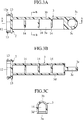
- the opening 1a of the cylinder 1 is also arched, as is clearly illustrated in FIG. 2A.
- a peak 5 is furnished over the arched portion of the opening 1a.
- the arched top surface 3b of the piston rod 3 slides along the peak 5 when the piston rod 3 is pulled out or inserted in the cylinder 1 during the operation of the air damper.
- FIG. 2 illustrates the cylinder 1 more clearly.
- a stopper 6 projects into the opening 1a so as to be opposed to the arched edge of the opening 1a.
- the stopper 6 is to be positioned between the sidewalls 3d of the piston rod 3 when the air damper is assembled, as illustrated by the ghost line in FIG. 2A.
- the opening 1a of the cylinder has enlarged portions 7 on both sides near the bottom. Accordingly, the sidewalls 3b of the piston rod 3 moves in and out through the opening 1a without conflicting with the frame of the opening 1a.
- the length of the peak 5 projects over the opening 1a by the length of ⁇ 1, as illustrated in FIG. 2B.
- Length ⁇ 1 is set so that hole 3e of the fixing ring 3c (FIGs. 1 and 3A) of the piston rod 3 does not hide under the peak 5 even if the piston rod 3 is completely inserted into the cylinder 1.
- the shape of the opening 1a and the contour of the piston rod 3 are similar, the stable motion of the piston rod 3 is guaranteed.
- the enlarged portions 7 of the opening 1a allow the piston rod 3 to move smoothly without touching the entire periphery of the opening 1a. Accordingly, the sliding resistance of the piston rod 3 can be reduced.
- An annular platform 8 is formed in the inner face of the cylinder near the other opening 1b.
- the annular platform 8 functions as a sealing face 8, which is to come into contact with the cap 4 when the piston rod 3 is pulled out of the cylinder 1.
- An outward annulus 9 is formed around the opening 1b at the position corresponding to the annular platform 8. The diameter of the annulus 9 is slightly greater than that of the cylinder 1. Indents for cutaways) 11 and holes 10 are formed alternately along the outward annulus 9 at a predetermined interval, as is clearly shown in FIG. 1.
- the cylinder 1 has fixing fins 1c with holes.
- the fixing fins 1c extend from the outer face of the cylinder 1 near both ends thereof.
- the fixing fins 1c is used when the air damper is attached to the glove box of an automobile.
- FIG. 3 illustrates the piston rod 3 and the piston 3 coupled to the piston rod 3.
- the piston rod 3 has a fixing ring 3c at the leading end.
- the plane defined by the fixing ring is perpendicular to a plane containing the opening 3a of the piston rod 3.
- the piston 2 is formed integrally with the piston rod 3.
- the piston 2 includes a disc 12, whose diameter is slightly smaller than the inner diameter of the cylinder 1.
- An annular bead 13 is formed around the disc 12.
- the annular bead 13 functions as a sealing bead 13 so that the piston 2 keeps contact with the inner face of the cylinder 1 even if the piston rod 3 moves in and out at the opening 1a.
- the diameter of the sealing bead 13 is slightly greater than the inner diameter of the cylinder 1.
- the annular bead 13 is also formed integrally with the piston rod 3.
- the annular beads 13 are formed in double with a groove 13a between them. The groove 13a absorbs the deformation of the annular beads 13 when the piston 2 moves in the cylinder 1.
- the piston rod 3 has an arched top surface 3b and the sidewalls 3d extending downward from the top surface 3b, with an opening 3a between the sidewalls 3d.
- the stopper 6 positioned at the opening 1a of the cylinder 1 is received between the sidewalls 3d of the piston rod 3 when the piston rod is assembled in the cylinder 1.
- Reinforcing ribs 14 extend inside the piston rod 3, and a fixing ring 3c is formed at the front end of the piston rod 3.
- the height of the rib 14 is set smaller than that of the piston rod 3 in order to avoid the interference with the stopper 6.
- the piston rod 3 and the piston 2 are made of an elastmer, and formed by, for example, molding.
- the piston rod 3 has an arched shell (or a continuous wall) and an opening 3a. This arrangement is suitable for resin molding. That is, the weight and the material cost are reduced, while achieving sufficient resin strength.
- the piston rod 3 has an arched cross-section, the piston rod 3 is not limited to this shape. As long as the piston rod 3 has an opening 3a and a continuous outer wall, an inverse U-shape, an inverse V-shape, or a downward C-shape, or other appropriate shape may be used. In either case, the molding process of the piston rod can be facilitated and the weight of the piston rod is reduced. It should be noted that if the shaped of the piston rod 3 is modified, the opening 1a of the cylinder 1 and the peak 5 are shaped in accordance with the contour of the piston rod 3.
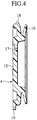
- FIG. 4 illustrates the cap 4.
- the cap 4 has a base disc 15 and the flange 16 extending outward in the radial direction of the base disc 15.
- the base disc 15 is to be fit into the outward annulus 9 formed at the opening 1b of the cylinder 1 in such a manner that the base disc 15 is slightly movable in the axial direction of the cylinder 1.
- An orifice 17 is formed near the center of the base disc 15.
- projections 18 and positioning pieces 19 are formed along the circumference of the base disc 15 at a predetermined interval.
- the holes 10 and the indents 11 are also formed at a predetermined interval along the outward annulus 9. If the piston rod 3 is pulled out of or inserted into the cylinder 1 (which means that the glove box is opened or closed), the flange 16 of the cap 4 comes into contact with or separates from the annular platform 8 of the cylinder 1 due to a pressure change in the cylinder 1.
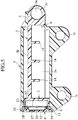
- the piston rod 3 and the piston 2 are inserted into the cylinder 1 from the opening 1b. Since the piston rod is made of an elastomer, the fixing ring 3c and the front face of the piston rod 3, from which the fixing rig 3c extends, deform and easily gets over the stopper 6. At this time, the stopper also slightly deforms. Then, the cap 4 is fit into the outward annulus 9 so that the positioning pieces 19 are received in the indents 11. The cap 4 is further pushed into the outward annulus 9 until the projections 18 of the cap 4 are fit into the hole 10. Thus, the one-way type air damper can be easily assembled, as illustrated in FIG. 5.
- the cylinder 1 is fixed to the instrument panel of the automobile in a pivotable manner using one of the fixing fins 1c (e.g., using the fixing fin 1c located near the opening 1b), and the piston rod 3 is fixed to the glove box via the fixing ring 3c.
- the piston ring 3c may be fixed to the instrument panel, and the fixing fin 1c of the cylinder may be fixed to the glove box.
- the air damper is installed so that the arched top surface 3b of the piston rod 3 is kept upward with the opening 3a facing down to prevent the dust from accumulating in the piston rod 3.
- the piston rod 3 is pulled out of the cylinder 1 via the opening 1a, and accordingly, the piston 2 moves in the cylinder 1 toward the opening 1a, as illustrated in FIG. 6.
- the pressure in the space between the cap 4 and the piston 2 lowers.
- the base disc 15 of the cap 4 is sucked into the cylinder 1 until the projections 18 abut against the edges of the holes 10 of the outward annulus 9 of the cylinder 1.
- the seal flange 16 of the cap 4 comes into contact with the sealing face (i.e., the annular platform) 8 of the cylinder 1.
- the orifice 17 becomes the only air passage through which the air can flow into the cylinder 1. This limited airflow produces a damper effect, and the glove box opens gently.
- the piston rod 3 is pulled out of the cylinder 1, while the arched surface 3b being guided by the peak 5.
- This arrangement guarantees the stable motion of the piston rod 3.
- the peak 5 protects the piston rod 3 from undesirable load or breakage, by making use of the leverage, even if the piston rod 3 is fully pulled out.
- the opening 3a of the piston rod 3 faces down, the dust is prevented from entering the cylinder during the operation of the air damper.
- the enlarged portions 7 formed on both sides of the opening 1a of the cylinder 1 allow the piston rod 3 to move smoothly without conflicting with the side edges of the opening 1a.
- This arrangement reduces the resistance between the opening 1a and the piston rod 3 during the operation of the air damper, while guaranteeing the rigidity for supporting the piston rod.
- high precession is generally given to the arched top surfaces 3b, whereas not so much attention is paid to the straight sidewalls. Accordingly, forming a gap between the opening 1a and the sidewalls of the piston rod 3 is rational.
- the piston rod 3 When closing the glove box, the piston rod 3 is gradually pushed into the cylinder 1.
- the piston 2 moves toward the opening 1b of the cylinder 1, and the pressure in the cylinder increases.
- This pressure change causes the base disc 15 of the cap 4 to move away from the cylinder until the projections 18 abut against the opposite edges of the holes 10.
- the flange 16 of the cap 4 separates from the annular platform (i.e., the sealing face) 8 and the air escapes from the cylinder 1. Consequently, the piston rod 3 returns to the initial position without much air resistance, and the glove box is closed smoothly.
- the stopper 6 Because the stopper 6 is formed at the lower edge of the opening 1a of the cylinder 1, the front end face of the piston rod 3, from which the fixing ring 3c extends, strikes the stopper 6 when the piston rod is fully pushed into the cylinder 1, as illustrated in FIG. 8. In other words, the stopper regulates the initial position (i.e., the fully-inserted position) of the piston rod 3. This arrangement prevents the cap 4 from coming off the opposite opening 1b of the cylinder 1.
- the height of the reinforcing rib 14 of the piston rod 3 is set smaller than that of the piston rod 3, so that the gap ⁇ 2 is maintained between the lower end of the reinforcing rib 14 and the top end of the stopper 6. Consequently, the piston rod 3 is inserted into the cylinder 1 without interference between the rib 14 and the stopper 6.
- the reinforcing ribs 14 extending inside the piston rod 3 further strengthen the rigidity, and give sufficient resistance against the bending stress or the torsional stress.
- Shaping the piston rod 3 into the arched shell has another advantage that the weight and the manufacturing cost are reduced, while improving the productivity and the appearance of the piston rod 3.
- the piston rod 3 Since the piston rod 3 is attached to the glove box with the opening 3a facing down to prevent the dust from entering the cylinder 1, the cylinder 1, the piston rod 3, and the piston 2 are protected from undesirable aberration or damage even if the glove box is frequently opened and closed. By preventing the frictional aberration or damage, the sealing effect between piston and the cylinder can be maintained.
- FIG 9 illustrates an air damper according to another embodiment in an exploded perspective view.
- the shell of the piston rod 33 is rotated by 90 degrees with respect to the fixing ring 33c.
- the opening 31a of the cylinder 31 is also rotated about the center axis of the cylinder.
- the piston rod 33 has a continuous outer wall, which consisting of an arched face 33b and sidewalls 33d that extending from the arched face 33b, and an opening 33a extending along the longitudinal axis of the piston rod 33.
- the piston rod 33 is sideways with respect to the fixing ring 33c.
- a plane containing the opening of the piston rod 33 is parallel to the plane defined by the fixing ring 33c.
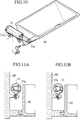
- the air damper shown in FIG. 9 is installed in the automobile so that the opening 33a of the piston rod 33 faces the side of the glove box 50, as illustrated in FIG. 10 and FIG. 11A.
- the fixing ring 33c of the piston rod 33 is fixed to the side of the glove box 50
- one of the fixing fin 31c of the cylinder 31 is fixed to the instrument panel 60 of the automobile.
- the opening 33a of the piston rod 33 faces the side of the glove box 50 at a very close position.
- This arrangement can prevent the dust accumulating in the piston rod 3 more efficiently than that of the previous embodiment.
- the opening 33a and the ribs extending inside the piston rod 33 are hidden behind the outer wall. Thus, the appearance of the air damper in actual use is improved.
- the air damper may be attached to the glove box so that the opening 33a of the piston rod 33 faces the instrument panel 60 at a close position, as illustrated in FIG. 11B.
- the cylinder 31 is fixed to the instrument panel 60 via the fixing fix 31c
- the piston rod 33 is fixed to the glove box via the fixing ring 33c.
- the piston rod 33 may be fixed to the instrument panel 60 and the cylinder 31 may be fixed to the glove box.
- the piston rod 3 is positioned so that the opening 3a faces down during the operation of the air damper, the opening 3a may be positioned at any angle lower than the horizontal line.
- the air damper may be used to any article that consists of a fixed body and a movable body.
- the air damper of the invention is suitably used to control the motion of the movable body relative to the fixed body.
Landscapes
- Engineering & Computer Science (AREA)
- General Engineering & Computer Science (AREA)
- Mechanical Engineering (AREA)
- Vehicle Step Arrangements And Article Storage (AREA)
- Fluid-Damping Devices (AREA)
Abstract
Description
- The present invention generally relates to an air damper, and more specifically, to an improved structure of a cylindrical air damper installed in, for example, the glove box of an automobile, which can efficiently prevents dust from entering the cylinder.
- A cylindrical air damper of the earlier technology is disclosed in, for example, Japanese Patent Application Laid-open No. 2000-65116. This type of air damper includes a cylinder having openings at both ends, and a piston movable in the cylinder while keeping tight contact with the inner face of the cylinder. A piston rod that has a cross-shaped cross sectional view is coupled to the piston. The piston rod extends through the opening of one end of the cylinder. A cap is provided to the other end of the cylinder so as to be slightly movable in response to a pressure change in the cylinder. A fin-like fixing piece extends from the outer surface of the cylinder near the other end. An annular shelf (or platform) is formed in the inner surface of the cylinder near the other end. This annular shelf becomes a sealing face that comes into contact with the cap.
- When using the conventional air damper in the glove box of an automobile, the other end of the cylinder is fixed to the instrument panel of the automobile via the fixing piece in a pivotable manner. The piston rod is fixed to the glove box. If the glove box is opened, the piston rod is pulled out of the cylinder via the opening, while causing the piston move along the cylinder. The pressure change in the cylinder causes the cap to come into tight contact with the sealing platform. In this sate, the air flow is only allows via the orifices formed in the base of the cap, which produces a damper effect and allows the glove box to open gently.
- When closing the glove box, the piston rod is inserted slowly in the cylinder, and the piston moves in the same direction. The motion of the piston causes a pressure change in the cylinder, and due to the pressure change, the cap separates from the sealing platform (or the sealing face). Consequently, the air flows out of the cylinder, and the piston can move smoothly in the cylinder. This allows the glove box to be closed promptly.
- Although the conventional air damper realizes a simple one-way air damper that makes use of a pressure change to causes the cap to engage with and disengage from the sealing platform, dust is easily accumulated in the space defined by the cross-shaped piston rod. The dust accumulated in the piston rod is likely to enter the cylinder during the operation of the piston. Once the dust enters the cylinder, the friction between the piston and the cylinder increases, and the interface between the cylinder and the piston is damaged or worn out.
- The present invention is conceived to overcome these problems in the air damper of the earlier technology.
- An air damper comprises a cylinder having first and second openings at both ends, a piston that moves in the cylinder, a piston rod coupled to the piston and moving in and out at the first opening of the cylinder, and a cap positioned at the second opening of the cylinder. The piston rod has a continuous outer wall and an opening extending along the longitudinal axis of the rod. The cap has an orifice and a sealing flange.
- The piston rod has an inverse U-shaped cross-section taken along a plane perpendicular to the longitudinal axis of the rod. Alternatively, the cross-sectional view of the piston rod may be an inverse V-shape, C-shape, or the like. The piston rod may take any shapes as long as it has a continuous outer wall and an opening.
- The piston rod has a fixing ring at a leading end. A plane containing the opening of the piston rod is perpendicular to a plane defined by the fixing ring. Alternatively, the plane containing the opening of the piston rod is parallel to the plane defined by the fixing ring.
- In another aspect of the invention, an air damper used to control a motion of a movable body relative to a fixed body is provided. This air damper comprises a cylinder having first and second opening at both ends, a piston that moves in the cylinder, a piston rod coupled to the piston and having a continuous outer wall and an opening extending along the longitudinal axis of the rod, the piston rod being fixed to either the movable body or the fixed body with the opening facing down. A cap having an orifice and a sealing flange is positioned at the second opening of the cylinder.
- In still another aspect of the invention, an air damper used to control a motion of a movable body relative to a fixed body comprises a cylinder having first and second opening at both ends, a piston that moves in the cylinder, a piston rod coupled to the piston and having a continuous outer wall and an opening extending along the longitudinal axis of the rod, piston rod being fixed to the movable body so that the opening faces the movable body.
- In still another aspect of the invention, an air damper used to control a motion of a movable body relative to a fixed body comprises a cylinder having first and second opening at both ends, a piston that moves in the cylinder, a piston rod coupled to the piston and having a continuous outer wall and an opening extending along the longitudinal axis of the rod, piston rod being fixed to the fixed body so that the opening faces the fixed body.
- Other objects, features, and advantages of the invention will be apparent from the following detailed description in conjunction with the attached drawings, in which:
- FIG. 1 is an exploded perspective view of an air damper according to an embodiment of the invention;
- FIG. 2A is a front view of the cylinder used in the air damper shown in FIG. 1, cross-sectional view of the piston used in the air damper shown in FIG. 1, and FIG. 2B is a cross-sectional side view of the cylinder;
- FIG. 3A is a cross-sectional side view of the piston and the piston rod extending from the piston, FIG. 3B is a cross-sectional view taken along the A-A line shown in FIG. 3A, and FIG..3C is a cross-sectional view taken along the B-B line in FIG. 3A;
- FIG. 4 is a cross-sectional view of the cap used in the air damper shown in FIG. 1;
- FIG. 5 is a cross-sectional view of the assembled air damper shown in FIG. 1; and
- FIG. 6 is a cross-sectional view of a part of the air damper, which illustrates how a damper effect is achieved when the piston rod is pulled out of the cylinder;
- FIG. 7 illustrates how the air is released from the cylinder when the piston rod is pushed into the cylinder;
- FIG. 8 illustrates how the position of the piston rod is restricted when the piston rod is completely inserted in the cylinder;
- FIG. 9 is an exploded perspective view of an air damper according to another embodiment of the invention; and
- FIG. 10 illustrates the air damper shown in FIG. 9 attached to the glove box of an automobile; and
- FIG. 11A is a cross-sectional front view of the air damper, in which the opening of the piston rod faces the side of the glove box, and FIG. 11B is a cross-sectional front view of the air damper, in which the opening of the piston rod faces the instrument panel.
-
- The improved structure of the air damper according to an embodiment was conceived to efficiently regulating the opening and closing motion of a box or a lid, while preventing the dust from entering the cylinder of the air damper during the operation of the air damper. Such an air damper is used in, for example, the glove box of an automobile.
- As illustrated in FIG. 1, the air damper according to an embodiment includes a
cylinder 1 withopenings 1a and 1b at both ends, apiston 2 that moves in thecylinder 1 while keeping tight contact with the inner face of thecylinder 1, apiston rod 3 extending from thepiston 2 and moving to and fro at the opening 1a, and acap 4 positioned at theother opening 1b. Thecap 4 is slightly movable at theopening 1b. - In the example of FIG. 1, the
piston rod 3 has an archedtop surface 3b and sidewalls 3d continuously extending from the archedtop surface 3b. The cross-sectional view of thepiston rod 3 is arched or inverse-U shaped with anopening 3a at the bottom, as illustrated in FIG. 3. The opening 1a of thecylinder 1 is also arched, as is clearly illustrated in FIG. 2A. Apeak 5 is furnished over the arched portion of the opening 1a. The archedtop surface 3b of thepiston rod 3 slides along thepeak 5 when thepiston rod 3 is pulled out or inserted in thecylinder 1 during the operation of the air damper. - FIG. 2 illustrates the
cylinder 1 more clearly. Astopper 6 projects into the opening 1a so as to be opposed to the arched edge of the opening 1a. Thestopper 6 is to be positioned between the sidewalls 3d of thepiston rod 3 when the air damper is assembled, as illustrated by the ghost line in FIG. 2A. - The opening 1a of the cylinder has enlarged
portions 7 on both sides near the bottom. Accordingly, thesidewalls 3b of thepiston rod 3 moves in and out through the opening 1a without conflicting with the frame of the opening 1a. - The length of the
peak 5 projects over the opening 1a by the length of Δ1, as illustrated in FIG. 2B. Length Δ1 is set so thathole 3e of the fixingring 3c (FIGs. 1 and 3A) of thepiston rod 3 does not hide under thepeak 5 even if thepiston rod 3 is completely inserted into thecylinder 1. - Since the shape of the opening 1a and the contour of the
piston rod 3 are similar, the stable motion of thepiston rod 3 is guaranteed. In addition, theenlarged portions 7 of the opening 1a allow thepiston rod 3 to move smoothly without touching the entire periphery of the opening 1a. Accordingly, the sliding resistance of thepiston rod 3 can be reduced. - An
annular platform 8 is formed in the inner face of the cylinder near theother opening 1b. Theannular platform 8 functions as a sealingface 8, which is to come into contact with thecap 4 when thepiston rod 3 is pulled out of thecylinder 1. Anoutward annulus 9 is formed around theopening 1b at the position corresponding to theannular platform 8. The diameter of theannulus 9 is slightly greater than that of thecylinder 1. Indents for cutaways) 11 and holes 10 are formed alternately along theoutward annulus 9 at a predetermined interval, as is clearly shown in FIG. 1. - The
cylinder 1 has fixingfins 1c with holes. The fixingfins 1c extend from the outer face of thecylinder 1 near both ends thereof. The fixingfins 1c is used when the air damper is attached to the glove box of an automobile. - FIG. 3 illustrates the
piston rod 3 and thepiston 3 coupled to thepiston rod 3. Thepiston rod 3 has a fixingring 3c at the leading end. In this embodiment, the plane defined by the fixing ring is perpendicular to a plane containing theopening 3a of thepiston rod 3. Preferably, thepiston 2 is formed integrally with thepiston rod 3. Thepiston 2 includes adisc 12, whose diameter is slightly smaller than the inner diameter of thecylinder 1. Anannular bead 13 is formed around thedisc 12. Theannular bead 13 functions as a sealingbead 13 so that thepiston 2 keeps contact with the inner face of thecylinder 1 even if thepiston rod 3 moves in and out at the opening 1a. To this sake, the diameter of the sealingbead 13 is slightly greater than the inner diameter of thecylinder 1. Preferably, theannular bead 13 is also formed integrally with thepiston rod 3. In this embodiment shown in FIGs 3A and 3B, theannular beads 13 are formed in double with agroove 13a between them. Thegroove 13a absorbs the deformation of theannular beads 13 when thepiston 2 moves in thecylinder 1. - As has already been explained above, the
piston rod 3 has an archedtop surface 3b and thesidewalls 3d extending downward from thetop surface 3b, with anopening 3a between the sidewalls 3d. Thestopper 6 positioned at the opening 1a of thecylinder 1 is received between the sidewalls 3d of thepiston rod 3 when the piston rod is assembled in thecylinder 1. Reinforcingribs 14 extend inside thepiston rod 3, and a fixingring 3c is formed at the front end of thepiston rod 3. The height of therib 14 is set smaller than that of thepiston rod 3 in order to avoid the interference with thestopper 6. - The
piston rod 3 and thepiston 2 are made of an elastmer, and formed by, for example, molding. As has been explained, thepiston rod 3 has an arched shell (or a continuous wall) and anopening 3a. This arrangement is suitable for resin molding. That is, the weight and the material cost are reduced, while achieving sufficient resin strength. Although, in the embodiment, thepiston rod 3 has an arched cross-section, thepiston rod 3 is not limited to this shape. As long as thepiston rod 3 has anopening 3a and a continuous outer wall, an inverse U-shape, an inverse V-shape, or a downward C-shape, or other appropriate shape may be used. In either case, the molding process of the piston rod can be facilitated and the weight of the piston rod is reduced. It should be noted that if the shaped of thepiston rod 3 is modified, the opening 1a of thecylinder 1 and thepeak 5 are shaped in accordance with the contour of thepiston rod 3. - FIG. 4 illustrates the
cap 4. Thecap 4 has abase disc 15 and theflange 16 extending outward in the radial direction of thebase disc 15. Thebase disc 15 is to be fit into theoutward annulus 9 formed at theopening 1b of thecylinder 1 in such a manner that thebase disc 15 is slightly movable in the axial direction of thecylinder 1. Anorifice 17 is formed near the center of thebase disc 15. As is clearly shown in FIGs. 1 and 4,projections 18 andpositioning pieces 19 are formed along the circumference of thebase disc 15 at a predetermined interval. When thecap 4 is fit into theopening 1b of thecylinder 1, theprojections 18 are fit into theholes 10 of theoutward annulus 9, andpositioning pieces 19 come into engagement with theindents 11. Theholes 10 and theindents 11 are also formed at a predetermined interval along theoutward annulus 9. If thepiston rod 3 is pulled out of or inserted into the cylinder 1 (which means that the glove box is opened or closed), theflange 16 of thecap 4 comes into contact with or separates from theannular platform 8 of thecylinder 1 due to a pressure change in thecylinder 1. - When assembling the air damper, the
piston rod 3 and thepiston 2 are inserted into thecylinder 1 from theopening 1b. Since the piston rod is made of an elastomer, the fixingring 3c and the front face of thepiston rod 3, from which the fixingrig 3c extends, deform and easily gets over thestopper 6. At this time, the stopper also slightly deforms. Then, thecap 4 is fit into theoutward annulus 9 so that thepositioning pieces 19 are received in theindents 11. Thecap 4 is further pushed into theoutward annulus 9 until theprojections 18 of thecap 4 are fit into thehole 10. Thus, the one-way type air damper can be easily assembled, as illustrated in FIG. 5. - To install this air damper in the glove box of an automobile, the
cylinder 1 is fixed to the instrument panel of the automobile in a pivotable manner using one of the fixingfins 1c (e.g., using the fixingfin 1c located near theopening 1b), and thepiston rod 3 is fixed to the glove box via the fixingring 3c. Alternatively, thepiston ring 3c may be fixed to the instrument panel, and the fixingfin 1c of the cylinder may be fixed to the glove box. In either case, the air damper is installed so that the archedtop surface 3b of thepiston rod 3 is kept upward with theopening 3a facing down to prevent the dust from accumulating in thepiston rod 3. - If the glove box is opened, the
piston rod 3 is pulled out of thecylinder 1 via the opening 1a, and accordingly, thepiston 2 moves in thecylinder 1 toward the opening 1a, as illustrated in FIG. 6. As thepiston 2 moves toward the opening 1a, the pressure in the space between thecap 4 and thepiston 2 lowers. Accordingly, thebase disc 15 of thecap 4 is sucked into thecylinder 1 until theprojections 18 abut against the edges of theholes 10 of theoutward annulus 9 of thecylinder 1. In this state, theseal flange 16 of thecap 4 comes into contact with the sealing face (i.e., the annular platform) 8 of thecylinder 1. Accordingly, theorifice 17 becomes the only air passage through which the air can flow into thecylinder 1. This limited airflow produces a damper effect, and the glove box opens gently. - As has been explained above, as the glove box opens, the
piston rod 3 is pulled out of thecylinder 1, while thearched surface 3b being guided by thepeak 5. This arrangement guarantees the stable motion of thepiston rod 3. Thepeak 5 protects thepiston rod 3 from undesirable load or breakage, by making use of the leverage, even if thepiston rod 3 is fully pulled out. In addition, since theopening 3a of thepiston rod 3 faces down, the dust is prevented from entering the cylinder during the operation of the air damper. - The
enlarged portions 7 formed on both sides of the opening 1a of thecylinder 1 allow thepiston rod 3 to move smoothly without conflicting with the side edges of the opening 1a. This arrangement reduces the resistance between the opening 1a and thepiston rod 3 during the operation of the air damper, while guaranteeing the rigidity for supporting the piston rod. In addition, when molding thepiston rod 3, high precession is generally given to the archedtop surfaces 3b, whereas not so much attention is paid to the straight sidewalls. Accordingly, forming a gap between the opening 1a and the sidewalls of thepiston rod 3 is rational. - When closing the glove box, the
piston rod 3 is gradually pushed into thecylinder 1. Thepiston 2 moves toward theopening 1b of thecylinder 1, and the pressure in the cylinder increases. This pressure change causes thebase disc 15 of thecap 4 to move away from the cylinder until theprojections 18 abut against the opposite edges of theholes 10. Theflange 16 of thecap 4 separates from the annular platform (i.e., the sealing face) 8 and the air escapes from thecylinder 1. Consequently, thepiston rod 3 returns to the initial position without much air resistance, and the glove box is closed smoothly. - Because the
stopper 6 is formed at the lower edge of the opening 1a of thecylinder 1, the front end face of thepiston rod 3, from which the fixingring 3c extends, strikes thestopper 6 when the piston rod is fully pushed into thecylinder 1, as illustrated in FIG. 8. In other words, the stopper regulates the initial position (i.e., the fully-inserted position) of thepiston rod 3. This arrangement prevents thecap 4 from coming off theopposite opening 1b of thecylinder 1. The height of the reinforcingrib 14 of thepiston rod 3 is set smaller than that of thepiston rod 3, so that the gap Δ2 is maintained between the lower end of the reinforcingrib 14 and the top end of thestopper 6. Consequently, thepiston rod 3 is inserted into thecylinder 1 without interference between therib 14 and thestopper 6. - Shaping the
piston rod 3 into an arch with a continuous outer wall, leaving anopening 3a at the bottom, improves the rigidity of thepiston rod 3 itself, as compared with the conventional cross-shaped piston rod. The reinforcingribs 14 extending inside thepiston rod 3 further strengthen the rigidity, and give sufficient resistance against the bending stress or the torsional stress. Shaping thepiston rod 3 into the arched shell has another advantage that the weight and the manufacturing cost are reduced, while improving the productivity and the appearance of thepiston rod 3. - Since the
piston rod 3 is attached to the glove box with theopening 3a facing down to prevent the dust from entering thecylinder 1, thecylinder 1, thepiston rod 3, and thepiston 2 are protected from undesirable aberration or damage even if the glove box is frequently opened and closed. By preventing the frictional aberration or damage, the sealing effect between piston and the cylinder can be maintained. - FIG 9 illustrates an air damper according to another embodiment in an exploded perspective view. In this example, the shell of the
piston rod 33 is rotated by 90 degrees with respect to the fixingring 33c. Similarly, theopening 31a of thecylinder 31 is also rotated about the center axis of the cylinder. - The
piston rod 33 has a continuous outer wall, which consisting of anarched face 33b and sidewalls 33d that extending from thearched face 33b, and anopening 33a extending along the longitudinal axis of thepiston rod 33. In this embodiment, thepiston rod 33 is sideways with respect to the fixingring 33c. In other words, a plane containing the opening of thepiston rod 33 is parallel to the plane defined by the fixingring 33c. - The air damper shown in FIG. 9 is installed in the automobile so that the
opening 33a of thepiston rod 33 faces the side of theglove box 50, as illustrated in FIG. 10 and FIG. 11A. In this example, the fixingring 33c of thepiston rod 33 is fixed to the side of theglove box 50, and one of the fixingfin 31c of thecylinder 31 is fixed to theinstrument panel 60 of the automobile. Theopening 33a of thepiston rod 33 faces the side of theglove box 50 at a very close position. This arrangement can prevent the dust accumulating in thepiston rod 3 more efficiently than that of the previous embodiment. When the glove box is opened and thepiston rod 33 is pulled out of thecylinder 31, only the smooth surface of the continuous outer wall of thepiston rod 33 appears. Unlike the previous embodiment, theopening 33a and the ribs extending inside thepiston rod 33 are hidden behind the outer wall. Thus, the appearance of the air damper in actual use is improved. - In an alternative example, the air damper may be attached to the glove box so that the
opening 33a of thepiston rod 33 faces theinstrument panel 60 at a close position, as illustrated in FIG. 11B. In the example shown in FIG. 11, thecylinder 31 is fixed to theinstrument panel 60 via the fixingfix 31c, and thepiston rod 33 is fixed to the glove box via the fixingring 33c. However, thepiston rod 33 may be fixed to theinstrument panel 60 and thecylinder 31 may be fixed to the glove box. - Although the present invention has been described based on specific embodiments, the invention will not be limited to these examples. It should be appreciated that there are many modifications and substitutions without departing from the scope of the invention. For example, although, in the previous embodiment, the
piston rod 3 is positioned so that theopening 3a faces down during the operation of the air damper, theopening 3a may be positioned at any angle lower than the horizontal line. The air damper may be used to any article that consists of a fixed body and a movable body. The air damper of the invention is suitably used to control the motion of the movable body relative to the fixed body.
Claims (14)
- An air damper comprising:a cylinder having first and second openings at both ends;a piston that moves in the cylinder;a piston rod coupled to the piston and moving in and out at the first opening of the cylinder; the piston rod having a continuous outer wall and an opening extending along the longitudinal axis of the rod; anda cap positioned at the second opening of the cylinder.
- The air damper of claim 1, wherein the first opening is shaped so as to be similar to a contour of the piston rod.
- The air damper of claim 2, wherein the first opening has a peak for guiding a part of the outer wall of the piston rod.
- The air damper of claim 1, wherein the piston rod has an inverse U-shaped cross-sectional view taken along a plane perpendicular to the longitudinal axis.
- The air damper of claim 1, wherein the piston rod has a C-shaped cross-sectional view taken along a plane perpendicular to the longitudinal axis.
- The air damper of claim 1, wherein the piston rod has an inverse V-shaped cross-sectional view taken along a plane perpendicular to the longitudinal axis.
- The air damper of claim 1, wherein the piston rod has a fixing ring at a leading end.
- The air damper of claim 7, wherein a plane containing the opening of the piston rod is perpendicular to a plane defined by the fixing ring.
- The air damper of claim 7, wherein a plane containing the opening of the piston rod is parallel to a plane defined by the fixing ring.
- The air damper of claim 1, wherein the piston rod has a reinforcing rib inside the outer wall.
- An air damper used to control a motion of a movable body relative to a fixed body, the air damper comprising:a cylinder having first and second opening at both ends;a piston that moves in the cylinder;a piston rod coupled to the piston and moving in and out at the first opening of the cylinder, the piston rod having a continuous outer wall and an opening extending along the longitudinal axis of the rod, and the piston rod being fixed to either the movable body or the fixed body with the opening facing downward; anda cap positioned at the second opening of the cylinder.
- An air damper used to control a motion of a movable body relative to a fixed body, the air damper comprising:a cylinder having first and second opening at both ends;a piston that moves in the cylinder;a piston rod coupled to the piston and moving in and out at the first opening of the cylinder, the piston rod having a continuous outer wall and an opening extending along the longitudinal axis of the rod, and the piston rod being fixed to the movable body so that the opening faces the movable body; anda cap positioned at the second opening of the cylinder.
- An air damper used to control a motion of a movable body relative to a fixed body, the air damper comprising:a cylinder having first and second opening at both ends;a piston that moves in the cylinder;a piston rod coupled to the piston and moving in and out at the first opening of the cylinder, the piston rod having a continuous outer wall and an opening extending along the longitudinal axis of the rod, and the piston rod being fixed to the fixed body so that the opening faces the fixed body; anda cap positioned at the second opening of the cylinder.
- An air damper comprising: a cylinder (1); a piston means (2) for reciprocal axial movement within the cylinder, movement in a first direction being damped and movement in a second direction being substantially un-damped; and piston rod means (3; 33) for moving the piston, the piston rod means being formed from an outer shell (3b, 3d; 33b, 33d) partially closed to form an elongate axially extending chamber, the shell having an opening (3a; 33a) which is orientated to reduce the introduction of dust into the chamber.
Applications Claiming Priority (2)
| Application Number | Priority Date | Filing Date | Title |
|---|---|---|---|
| JP2000255858A JP3912966B2 (en) | 2000-08-25 | 2000-08-25 | Air damper |
| JP2000255858 | 2000-08-25 |
Publications (3)
| Publication Number | Publication Date |
|---|---|
| EP1182373A2 true EP1182373A2 (en) | 2002-02-27 |
| EP1182373A3 EP1182373A3 (en) | 2003-09-10 |
| EP1182373B1 EP1182373B1 (en) | 2006-11-08 |
Family
ID=18744574
Family Applications (1)
| Application Number | Title | Priority Date | Filing Date |
|---|---|---|---|
| EP01307208A Expired - Lifetime EP1182373B1 (en) | 2000-08-25 | 2001-08-24 | Air damper used in glove box of automobile |
Country Status (5)
| Country | Link |
|---|---|
| US (1) | US6578832B2 (en) |
| EP (1) | EP1182373B1 (en) |
| JP (1) | JP3912966B2 (en) |
| KR (1) | KR100485272B1 (en) |
| DE (1) | DE60124353T2 (en) |
Families Citing this family (10)
| Publication number | Priority date | Publication date | Assignee | Title |
|---|---|---|---|---|
| DE20120112U1 (en) * | 2001-12-12 | 2002-02-21 | Arturo Salice S.P.A., Novedrate, Como | Air damper for moving furniture parts |
| JP3994042B2 (en) * | 2002-09-20 | 2007-10-17 | 株式会社パイオラックス | String type air damper |
| JP4041812B2 (en) | 2004-07-14 | 2008-02-06 | 本田技研工業株式会社 | Air damper |
| KR100760612B1 (en) * | 2006-09-27 | 2007-09-28 | 동국실업 주식회사 | An air damper |
| CN101784812B (en) * | 2007-08-31 | 2012-11-14 | 百乐仕株式会社 | Damper device |
| JP5048453B2 (en) * | 2007-10-25 | 2012-10-17 | 株式会社ニフコ | Damper and door handle with this damper |
| US20090106934A1 (en) * | 2007-10-31 | 2009-04-30 | Gm Global Technology Operations, Inc. | Vehicle Closure Check Link |
| JP5552412B2 (en) * | 2010-10-26 | 2014-07-16 | 株式会社ニフコ | Piston damper |
| US8356386B2 (en) * | 2011-05-11 | 2013-01-22 | Nan Juen International Co., Ltd. | Door closer |
| DE202011106896U1 (en) | 2011-10-19 | 2011-11-09 | ACE Stoßdämpfer GmbH | Rotary brake device and use of a rotary brake device in the automotive industry |
Citations (5)
| Publication number | Priority date | Publication date | Assignee | Title |
|---|---|---|---|---|
| JPS63190946A (en) * | 1987-02-02 | 1988-08-08 | Nifco Inc | Cylinder-type air damper |
| US4856625A (en) * | 1987-03-13 | 1989-08-15 | Nifco Inc. | Cylinder type air damper with filter for storage box |
| US5165324A (en) * | 1990-10-16 | 1992-11-24 | Nifco Inc. | Piston-cylinder type air damper |
| JP2000065116A (en) * | 1998-08-24 | 2000-03-03 | Piolax Inc | Air damper |
| US6062352A (en) * | 1998-08-24 | 2000-05-16 | Piolax, Inc. | Air damper |
Family Cites Families (11)
| Publication number | Priority date | Publication date | Assignee | Title |
|---|---|---|---|---|
| JPS6016029U (en) * | 1983-07-14 | 1985-02-02 | 株式会社 ニフコ | Piston cylinder type damper |
| JPH077638Y2 (en) * | 1988-10-24 | 1995-02-22 | 株式会社ニフコ | Cylinder type air damper |
| US5697477A (en) * | 1994-10-07 | 1997-12-16 | Nifco Inc. | Air damper |
| DE29610915U1 (en) * | 1996-06-21 | 1996-08-29 | Hörauf & Kohler KG, 86199 Augsburg | Pneumatic damper |
| KR100214416B1 (en) * | 1996-12-20 | 1999-08-02 | 정몽규 | Glove box open-close speed controller |
| US6497602B2 (en) * | 1998-10-14 | 2002-12-24 | Interlego Ag | Shock absorber for a toy building element |
| JP3321665B2 (en) * | 1998-11-06 | 2002-09-03 | 株式会社パイオラックス | Air damper |
| JP4260949B2 (en) * | 1998-12-07 | 2009-04-30 | 株式会社ニフコ | Air damper |
| JP3475327B2 (en) * | 1999-10-08 | 2003-12-08 | 株式会社パイオラックス | Air damper |
| JP3513650B2 (en) * | 2000-01-07 | 2004-03-31 | 株式会社パイオラックス | Air damper |
| DE10021762B4 (en) * | 2000-05-04 | 2006-03-16 | Itw-Ateco Gmbh | Air damper for a movably mounted component, in particular in automobiles |
-
2000
- 2000-08-25 JP JP2000255858A patent/JP3912966B2/en not_active Expired - Fee Related
-
2001
- 2001-08-22 US US09/934,958 patent/US6578832B2/en not_active Expired - Lifetime
- 2001-08-24 EP EP01307208A patent/EP1182373B1/en not_active Expired - Lifetime
- 2001-08-24 DE DE60124353T patent/DE60124353T2/en not_active Expired - Lifetime
- 2001-08-25 KR KR10-2001-0051557A patent/KR100485272B1/en not_active IP Right Cessation
Patent Citations (5)
| Publication number | Priority date | Publication date | Assignee | Title |
|---|---|---|---|---|
| JPS63190946A (en) * | 1987-02-02 | 1988-08-08 | Nifco Inc | Cylinder-type air damper |
| US4856625A (en) * | 1987-03-13 | 1989-08-15 | Nifco Inc. | Cylinder type air damper with filter for storage box |
| US5165324A (en) * | 1990-10-16 | 1992-11-24 | Nifco Inc. | Piston-cylinder type air damper |
| JP2000065116A (en) * | 1998-08-24 | 2000-03-03 | Piolax Inc | Air damper |
| US6062352A (en) * | 1998-08-24 | 2000-05-16 | Piolax, Inc. | Air damper |
Non-Patent Citations (2)
| Title |
|---|
| PATENT ABSTRACTS OF JAPAN vol. 012, no. 466 (M-772), 7 December 1988 (1988-12-07) & JP 63 190946 A (NIFCO INC), 8 August 1988 (1988-08-08) * |
| PATENT ABSTRACTS OF JAPAN vol. 2000, no. 06, 22 September 2000 (2000-09-22) & JP 2000 065116 A (PIOLAX INC;TOYOTA MOTOR CORP), 3 March 2000 (2000-03-03) * |
Also Published As
| Publication number | Publication date |
|---|---|
| JP2002070910A (en) | 2002-03-08 |
| KR20020016602A (en) | 2002-03-04 |
| JP3912966B2 (en) | 2007-05-09 |
| EP1182373A3 (en) | 2003-09-10 |
| DE60124353T2 (en) | 2007-06-21 |
| DE60124353D1 (en) | 2006-12-21 |
| KR100485272B1 (en) | 2005-04-25 |
| EP1182373B1 (en) | 2006-11-08 |
| US6578832B2 (en) | 2003-06-17 |
| US20020043437A1 (en) | 2002-04-18 |
Similar Documents
| Publication | Publication Date | Title |
|---|---|---|
| EP1182373A2 (en) | Air damper used in glove box of automobile | |
| CA2345910C (en) | Air damper for a movably supported structural part, in particular in automobiles | |
| JP5254235B2 (en) | Damper device | |
| JP2008532829A (en) | Weatherstrip with air vents | |
| US6220583B1 (en) | Air damper with hook on piston | |
| JP2011027209A (en) | Cushion clip | |
| WO2010131682A1 (en) | Air damper | |
| US6442796B2 (en) | Air damper | |
| US6062352A (en) | Air damper | |
| GB2407119A (en) | Weatherstrip | |
| KR100716591B1 (en) | String type air damper | |
| JP2547912Y2 (en) | Piston cylinder type air damper | |
| KR20130136461A (en) | Piston damper | |
| JP2007064245A (en) | Air damper | |
| JP3625665B2 (en) | Air damper | |
| WO2018174024A1 (en) | Air damper | |
| JP2005291327A (en) | Air damper | |
| JP4484745B2 (en) | Air damper | |
| KR101232843B1 (en) | Air Damper | |
| KR100516724B1 (en) | Door-gasket for refrigerator | |
| JP7237749B2 (en) | Fittings | |
| WO2014013651A1 (en) | Damper | |
| KR19990004015A (en) | Stay damper structure for car back door | |
| KR20030008786A (en) | device for prevention droop tail gate of vehicle | |
| JPS6112424Y2 (en) |
Legal Events
| Date | Code | Title | Description |
|---|---|---|---|
| PUAI | Public reference made under article 153(3) epc to a published international application that has entered the european phase |
Free format text: ORIGINAL CODE: 0009012 |
|
| AK | Designated contracting states |
Kind code of ref document: A2 Designated state(s): AT BE CH CY DE DK ES FI FR GB GR IE IT LI LU MC NL PT SE TR |
|
| AX | Request for extension of the european patent |
Free format text: AL;LT;LV;MK;RO;SI |
|
| PUAL | Search report despatched |
Free format text: ORIGINAL CODE: 0009013 |
|
| AK | Designated contracting states |
Kind code of ref document: A3 Designated state(s): AT BE CH CY DE DK ES FI FR GB GR IE IT LI LU MC NL PT SE TR |
|
| AX | Request for extension of the european patent |
Extension state: AL LT LV MK RO SI |
|
| RIC1 | Information provided on ipc code assigned before grant |
Ipc: 7F 16F 9/32 B Ipc: 7F 16F 9/02 A |
|
| 17P | Request for examination filed |
Effective date: 20031107 |
|
| AKX | Designation fees paid |
Designated state(s): DE FR GB |
|
| 17Q | First examination report despatched |
Effective date: 20040524 |
|
| GRAP | Despatch of communication of intention to grant a patent |
Free format text: ORIGINAL CODE: EPIDOSNIGR1 |
|
| GRAS | Grant fee paid |
Free format text: ORIGINAL CODE: EPIDOSNIGR3 |
|
| GRAA | (expected) grant |
Free format text: ORIGINAL CODE: 0009210 |
|
| AK | Designated contracting states |
Kind code of ref document: B1 Designated state(s): DE FR GB |
|
| REG | Reference to a national code |
Ref country code: GB Ref legal event code: FG4D |
|
| REF | Corresponds to: |
Ref document number: 60124353 Country of ref document: DE Date of ref document: 20061221 Kind code of ref document: P |
|
| ET | Fr: translation filed | ||
| PLBE | No opposition filed within time limit |
Free format text: ORIGINAL CODE: 0009261 |
|
| STAA | Information on the status of an ep patent application or granted ep patent |
Free format text: STATUS: NO OPPOSITION FILED WITHIN TIME LIMIT |
|
| 26N | No opposition filed |
Effective date: 20070809 |
|
| REG | Reference to a national code |
Ref country code: FR Ref legal event code: PLFP Year of fee payment: 16 |
|
| REG | Reference to a national code |
Ref country code: FR Ref legal event code: PLFP Year of fee payment: 17 |
|
| REG | Reference to a national code |
Ref country code: FR Ref legal event code: PLFP Year of fee payment: 18 |
|
| PGFP | Annual fee paid to national office [announced via postgrant information from national office to epo] |
Ref country code: GB Payment date: 20200813 Year of fee payment: 20 Ref country code: FR Payment date: 20200715 Year of fee payment: 20 Ref country code: DE Payment date: 20200812 Year of fee payment: 20 |
|
| REG | Reference to a national code |
Ref country code: DE Ref legal event code: R071 Ref document number: 60124353 Country of ref document: DE |
|
| REG | Reference to a national code |
Ref country code: GB Ref legal event code: PE20 Expiry date: 20210823 |
|
| PG25 | Lapsed in a contracting state [announced via postgrant information from national office to epo] |
Ref country code: GB Free format text: LAPSE BECAUSE OF EXPIRATION OF PROTECTION Effective date: 20210823 |