EP1182102A1 - Diebstahlsicherungsvorrichtung für Kraftfahrzeuge - Google Patents
Diebstahlsicherungsvorrichtung für Kraftfahrzeuge Download PDFInfo
- Publication number
- EP1182102A1 EP1182102A1 EP00307131A EP00307131A EP1182102A1 EP 1182102 A1 EP1182102 A1 EP 1182102A1 EP 00307131 A EP00307131 A EP 00307131A EP 00307131 A EP00307131 A EP 00307131A EP 1182102 A1 EP1182102 A1 EP 1182102A1
- Authority
- EP
- European Patent Office
- Prior art keywords
- steering wheel
- head portion
- theft prevention
- prevention device
- rotatable
- Prior art date
- Legal status (The legal status is an assumption and is not a legal conclusion. Google has not performed a legal analysis and makes no representation as to the accuracy of the status listed.)
- Withdrawn
Links
- 230000002265 prevention Effects 0.000 title claims abstract description 26
- 239000002184 metal Substances 0.000 abstract description 3
- 238000003780 insertion Methods 0.000 description 1
- 230000037431 insertion Effects 0.000 description 1
- 238000012986 modification Methods 0.000 description 1
- 230000004048 modification Effects 0.000 description 1
- 238000006748 scratching Methods 0.000 description 1
- 230000002393 scratching effect Effects 0.000 description 1
Images


Classifications
-
- B—PERFORMING OPERATIONS; TRANSPORTING
- B60—VEHICLES IN GENERAL
- B60R—VEHICLES, VEHICLE FITTINGS, OR VEHICLE PARTS, NOT OTHERWISE PROVIDED FOR
- B60R25/00—Fittings or systems for preventing or indicating unauthorised use or theft of vehicles
- B60R25/01—Fittings or systems for preventing or indicating unauthorised use or theft of vehicles operating on vehicle systems or fittings, e.g. on doors, seats or windscreens
- B60R25/02—Fittings or systems for preventing or indicating unauthorised use or theft of vehicles operating on vehicle systems or fittings, e.g. on doors, seats or windscreens operating on the steering mechanism
- B60R25/022—Fittings or systems for preventing or indicating unauthorised use or theft of vehicles operating on vehicle systems or fittings, e.g. on doors, seats or windscreens operating on the steering mechanism operating on the steering wheel, e.g. bars locked to the steering wheel rim
- B60R25/0225—Fittings or systems for preventing or indicating unauthorised use or theft of vehicles operating on vehicle systems or fittings, e.g. on doors, seats or windscreens operating on the steering mechanism operating on the steering wheel, e.g. bars locked to the steering wheel rim using a rod locked on the steering wheel rim
Definitions
- This invention relates to theft prevention devices for vehicles such as automobiles.
- the head portion which is a hollow cylindrical tube, is divided longitudinally into two equal parts. The two parts are longitudinally connected in a foldable manner with a hinge at one end region of the tube. Located at the other region of the first half of the tube is a long slot that can cover one segment of a steering wheel. At the corresponding region of the second half of the tube, there is a protrusion at a central region along the length of the long slot in the first half of the tube.
- This protrusion separates the long slot in the first half into two parts. Locking the steering wheel is achieved by closing the first and second halves of the tube together.
- the handle portion thereafter extends lengthwise from the tube or head portion and stretches out across the steering wheel in a co-planar manner, thereby preventing the steering wheel from turning.
- a theft prevention device for vehicles having a steering wheel such as automobiles
- the device comprising a hollow tubular head portion (100) including a longitudinal slot for covering and partially enclosing an annulus portion (20) of the steering wheel; a part-cylindrical rotatable steering wheel locking sleeve assembly (4) having a radius of curvature corresponding to the inner radius of the head portion and having in a middle region a locking protrusion or catch (41) adapted to act as a catch to extend behind a portion of the steering wheel in order to lock it relative to the theft prevention device, one end of the rotatable sleeve being fixed for rotation to a rotatable shaft (10) co-axial with but remote from the hollow head portion; a flange (42) on the end of the rotatable sleeve assembly (4) remote from the rotatable shaft (10) and including a stop member (5) adapted to cooperate with a lock mechanism assembly (2); the lock mechanism assembly having a protrusion
- the theft prevention device for automobiles or the like is intended to overcome the above-mentioned problems.
- the steering wheel locking mechanism is designed to include a head portion comprised of a hollow tube having a longitudinal slot that can be fitted onto a part of the steering wheel but is not divided into two parts, as in the prior art theft prevention device.
- the slot in the head portion of the theft prevention device is placed over part of the steering wheel and the rotatable shaft, which may correspond to the handle portion of a baseball bat, is then turned such that the locking protrusion or catch then extends behind part of the steering wheel and is thereafter locked in place by the lock mechanism assembly.
- This is convenient to use and can be applied to steering wheels of most types, for vehicles with left-hand or right-hand steering.
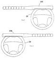
- a theft prevention device for vehicles in this example is shown in the shape of a baseball bat comprising a head portion 100 made of a strong hollow cylindrical metal tube and a handle portion 11. Within the head portion 1 there extends a longitudinal slot 8 for receiving an annulus portion of a steering wheel 20, as shown in Figures 5 and 6.
- a steering wheel locking sleeve assembly 4 is made of strong metal plate having its radius of curvature corresponding to the inner radius of curvature of the head portion 100.
- the radius of curvature of the locking sleeve assembly 4 is about one quarter of the circumference of the head portion 100.
- the length of the locking sleeve assembly 4 is nearly equal to the length of the head portion 100.
- a locking protrusion or catch 41 Located at the longitudinal middle of the locking sleeve assembly 4 is a locking protrusion or catch 41 which extends beyond the radius of curvature of the sleeve itself and is adapted to be received around part of the steering wheel 20 so as to lock the theft prevention device to it.
- a connecting portion 6 that connects it to a rotational rod or shaft 10 by an annular flange 43.
- a rotational shaft holding assembly or collar 9 is attached to the end of the head portion 100 adjacent to the handle 11 so as to position the rotational shaft 10 co-axially therewith.
- On the upper end of the shaft 10 is an insertion receptacle or ferrule 44 rotationally connected, with respect to the tube 100, to the annular flange 43 of the locking sleeve assembly 4 by a bolt 7.
- An upper annular flange 42 at the other end of the locking sleeve assembly 4 has a reverse rotation stop portion 5 that supports or co-operates with a lock mechanism assembly 2 on the end of the head portion 100 remote from the handle 11.
- the lock mechanism assembly 2 is inserted through a lock mechanism holding portion or mounting sleeve 3 attached to the head portion 100 and is covered by a lid or cover 1 on the upper side thereof.
- the rotational shaft 10 is covered and encapsulated by the handle 11 so as to fit closely thereto thereby to prevent the shaft 10 from scratching, e.g. the body, of an automobile.
- the lock mechanism assembly 2 is connected to the locking mechanism mounting sleeve 3 with a bolt 12.
- a cam-like protrusion 31 that projects from the lock shaft and can be turned by unlocking with a key (not shown).
- This cam-like protrusion 31 is located in a lock shaft groove 32 that is activated by a spring 33 at one side. The other side engages with a toothed portion that is located in the reverse rotation stop portion 5. This rotates the steering wheel locking sleeve assembly 4 in only one direction, e.g. clock-wise, such that it is therefore unable to be turned reversibly.
- this cam-like protrusion 31 cooperates with the lock shaft groove and moves the lock shaft backwards.
- the lock shaft is then disengaged from the toothed portion located in the reverse rotation stop portion 5, thereby enabling the steering wheel locking sleeve 4 to be turned reversibly.
- the theft prevention device for vehicles such as automobiles is shown in Figure 3 in the unlocked position.
- the locking protrusion or catch 41 of the locking sleeve assembly 4 is shown in the non-protruding position within the slot 8 of the baseball bat-shaped head portion 100.
- the catch 41 of the locking sleeve assembly 4 protrudes into the slotted region 8 and can therefore be inserted within the annulus of a steering wheel, as can be seen clearly in Figures 5 and 6, wherein the theft prevention device, in this case for automobiles, is shown in the locked position.
- FIGS 5 and 6 show how to use the theft prevention device according to the invention where it can be used to lock the steering wheel of both right-hand and left-hand drive vehicles.
Landscapes
- Engineering & Computer Science (AREA)
- Mechanical Engineering (AREA)
- Lock And Its Accessories (AREA)
Priority Applications (1)
| Application Number | Priority Date | Filing Date | Title |
|---|---|---|---|
| EP00307131A EP1182102A1 (de) | 2000-08-21 | 2000-08-21 | Diebstahlsicherungsvorrichtung für Kraftfahrzeuge |
Applications Claiming Priority (1)
| Application Number | Priority Date | Filing Date | Title |
|---|---|---|---|
| EP00307131A EP1182102A1 (de) | 2000-08-21 | 2000-08-21 | Diebstahlsicherungsvorrichtung für Kraftfahrzeuge |
Publications (1)
| Publication Number | Publication Date |
|---|---|
| EP1182102A1 true EP1182102A1 (de) | 2002-02-27 |
Family
ID=8173201
Family Applications (1)
| Application Number | Title | Priority Date | Filing Date |
|---|---|---|---|
| EP00307131A Withdrawn EP1182102A1 (de) | 2000-08-21 | 2000-08-21 | Diebstahlsicherungsvorrichtung für Kraftfahrzeuge |
Country Status (1)
| Country | Link |
|---|---|
| EP (1) | EP1182102A1 (de) |
Citations (3)
| Publication number | Priority date | Publication date | Assignee | Title |
|---|---|---|---|---|
| US5129245A (en) * | 1991-08-12 | 1992-07-14 | Chang Peter J H | Telescopic steering lock |
| US5258741A (en) * | 1990-05-18 | 1993-11-02 | Innovision Technologies Group, Inc. | Portable anti-theft alarm and locking device for vehicles |
| US5325688A (en) * | 1993-05-10 | 1994-07-05 | Jaw Jia J | Assembly optional multi-purpose automobile lock |
-
2000
- 2000-08-21 EP EP00307131A patent/EP1182102A1/de not_active Withdrawn
Patent Citations (3)
| Publication number | Priority date | Publication date | Assignee | Title |
|---|---|---|---|---|
| US5258741A (en) * | 1990-05-18 | 1993-11-02 | Innovision Technologies Group, Inc. | Portable anti-theft alarm and locking device for vehicles |
| US5129245A (en) * | 1991-08-12 | 1992-07-14 | Chang Peter J H | Telescopic steering lock |
| US5325688A (en) * | 1993-05-10 | 1994-07-05 | Jaw Jia J | Assembly optional multi-purpose automobile lock |
Similar Documents
| Publication | Publication Date | Title |
|---|---|---|
| US5941108A (en) | Push button for a tubular lock unlockable by an inside handle thereof | |
| US4738127A (en) | Automobile steering lock | |
| US5678433A (en) | Antitheft device for locking the steering wheel of any kind of vehicle | |
| US4856308A (en) | Automobile steering lock | |
| US5381679A (en) | Vehicle steering wheel anti-theft devices | |
| JPH03135862A (ja) | ハンドルロック及び盗難防止用自動車係止法 | |
| US4655059A (en) | Lever handle | |
| US5704233A (en) | Anti-theft device for vehicles | |
| US5647234A (en) | Vehicle locking system | |
| US5277042A (en) | Automotive, steering wheel anti-theft device | |
| GB2259893A (en) | Anti-theft steering wheel lock | |
| US6705138B1 (en) | Clutch mechanism for a lock | |
| US5129245A (en) | Telescopic steering lock | |
| US5724838A (en) | Anti-theft device for a motor vehicle | |
| US11173828B2 (en) | Stake pocket accessories having a locking mechanism | |
| US5165264A (en) | Telescopic lock device for a steering wheel in an automobile | |
| US11801804B1 (en) | Secure locking hub system | |
| US5230232A (en) | Steering wheel lock | |
| US5257518A (en) | Locking device for locking a steering wheel of a car | |
| EP1182102A1 (de) | Diebstahlsicherungsvorrichtung für Kraftfahrzeuge | |
| US5325688A (en) | Assembly optional multi-purpose automobile lock | |
| CA2254353C (en) | Lock with improved torsional strength | |
| GB2359531A (en) | Bar type steering wheel mounted vehicle anti-theft device | |
| CA2317639A1 (en) | Theft prevention device for automobiles | |
| US5582045A (en) | Anti-theft device for attachment to a steering wheel in a motor vehicle |
Legal Events
| Date | Code | Title | Description |
|---|---|---|---|
| PUAI | Public reference made under article 153(3) epc to a published international application that has entered the european phase |
Free format text: ORIGINAL CODE: 0009012 |
|
| AK | Designated contracting states |
Kind code of ref document: A1 Designated state(s): AT BE CH CY DE DK ES FI FR GB GR IE IT LI LU MC NL PT SE |
|
| AX | Request for extension of the european patent |
Free format text: AL;LT;LV;MK;RO;SI |
|
| RIN1 | Information on inventor provided before grant (corrected) |
Inventor name: SOMBATJIRAKAL, CHALERMPONG |
|
| AKX | Designation fees paid | ||
| REG | Reference to a national code |
Ref country code: DE Ref legal event code: 8566 |
|
| STAA | Information on the status of an ep patent application or granted ep patent |
Free format text: STATUS: THE APPLICATION IS DEEMED TO BE WITHDRAWN |
|
| 18D | Application deemed to be withdrawn |
Effective date: 20020828 |