EP1181663B1 - Portable mini-card sized module reader for connection to the port of a personal computer - Google Patents
Portable mini-card sized module reader for connection to the port of a personal computer Download PDFInfo
- Publication number
- EP1181663B1 EP1181663B1 EP00927338A EP00927338A EP1181663B1 EP 1181663 B1 EP1181663 B1 EP 1181663B1 EP 00927338 A EP00927338 A EP 00927338A EP 00927338 A EP00927338 A EP 00927338A EP 1181663 B1 EP1181663 B1 EP 1181663B1
- Authority
- EP
- European Patent Office
- Prior art keywords
- reader
- module
- computer
- port
- electrically connected
- Prior art date
- Legal status (The legal status is an assumption and is not a legal conclusion. Google has not performed a legal analysis and makes no representation as to the accuracy of the status listed.)
- Expired - Lifetime
Links
Images
Classifications
-
- G—PHYSICS
- G06—COMPUTING OR CALCULATING; COUNTING
- G06K—GRAPHICAL DATA READING; PRESENTATION OF DATA; RECORD CARRIERS; HANDLING RECORD CARRIERS
- G06K19/00—Record carriers for use with machines and with at least a part designed to carry digital markings
- G06K19/06—Record carriers for use with machines and with at least a part designed to carry digital markings characterised by the kind of the digital marking, e.g. shape, nature, code
- G06K19/067—Record carriers with conductive marks, printed circuits or semiconductor circuit elements, e.g. credit or identity cards also with resonating or responding marks without active components
- G06K19/07—Record carriers with conductive marks, printed circuits or semiconductor circuit elements, e.g. credit or identity cards also with resonating or responding marks without active components with integrated circuit chips
- G06K19/077—Constructional details, e.g. mounting of circuits in the carrier
- G06K19/07737—Constructional details, e.g. mounting of circuits in the carrier the record carrier consisting of two or more mechanically separable parts
- G06K19/07741—Constructional details, e.g. mounting of circuits in the carrier the record carrier consisting of two or more mechanically separable parts comprising a first part operating as a regular record carrier and a second attachable part that changes the functional appearance of said record carrier, e.g. a contact-based smart card with an adapter part which, when attached to the contact card makes the contact card function as a non-contact card
-
- G—PHYSICS
- G06—COMPUTING OR CALCULATING; COUNTING
- G06F—ELECTRIC DIGITAL DATA PROCESSING
- G06F21/00—Security arrangements for protecting computers, components thereof, programs or data against unauthorised activity
-
- G—PHYSICS
- G06—COMPUTING OR CALCULATING; COUNTING
- G06K—GRAPHICAL DATA READING; PRESENTATION OF DATA; RECORD CARRIERS; HANDLING RECORD CARRIERS
- G06K7/00—Methods or arrangements for sensing record carriers, e.g. for reading patterns
- G06K7/0013—Methods or arrangements for sensing record carriers, e.g. for reading patterns by galvanic contacts, e.g. card connectors for ISO-7816 compliant smart cards or memory cards, e.g. SD card readers
- G06K7/0021—Methods or arrangements for sensing record carriers, e.g. for reading patterns by galvanic contacts, e.g. card connectors for ISO-7816 compliant smart cards or memory cards, e.g. SD card readers for reading/sensing record carriers having surface contacts
Definitions
- the invention relates to portable readers and in particular to portable readers.
- portable modules in mini-card format as defined in appendix A of the standard ETSI / GSM 11.11 in version 5.3.0 of July 1996.
- modules are mainly used in mobile telephony for identify their bearer with an operator managing a network of GSM type telecommunications (Global System for Mobile communications).
- GSM Global System for Mobile communications
- these modules are also capable of fulfilling many other functions.
- the modules include application programs, especially written in computer languages high-level, which allow them, as part of a connection to a network of telecommunications, ensuring electronic transactions, ensuring running games or even implementing messaging functions.
- these programs are limited in memory size and in their speed of execution.
- the modules are secure, portable and little expensive and therefore of great interest.
- EP - A - 883 083 describes a memory "memory stick" where the memory is not installed separable. Indeed, this document does not describe a reader.
- US 5,276,317 describes an object for keeping SIM modules, for example associated with a key ring. Document does not mention a reader electrically connected to a port on a computer.
- gateways are being put in place between different networks.
- such gateways are implemented between a company's internal computer networks and public networks in the internet type, or even between telecommunications networks and such public networks.
- a problem which we propose to solve the invention relates to means allowing practical and entirely management secure data, in particular personal data, intended for use within Informatic Systems.
- the present invention is as defined in the claims of which the preambles consist by the features described above.
- the reader whose dimensions are reduced, can be connected to a adequate port of a computer, disconnected from it and transported with its module and the confidential data it contains.
- the module itself can be removed from the reader and plugged into another device such as a telephone mobile where the confidential data it contains can be used.
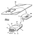
- the invention relates to a portable reader 1.
- Such a reader 1 has a weight of the order of a few grams. It is part of a rectangular parallelepiped whose dimensions, length, width and thickness, are respectively of the order of 5, 3 and 2 cm. Also, a reader 1 depending the invention can be associated with a key ring and / or be carried in a pocket of its holder.
- the reader 1 comprises an electrical connection part 2 to a port 3 of a personal computer or other computer processing equipment data as well as an insertion part 4 of a removable electronic module 5.
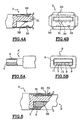
- the electrical connection part 2 presents a plastic tip 6 of rectangular section the open end of which has a plastic support element 7 on the surface from which there are four parallel metallized lines, and four lines only, forming a connector for an electrical connection of reader 1 at port 3. These lines are placed substantially halfway up in the nozzle 6.
- a first line 8 is intended for supplying current Vbus to the reader, a second 9 and a third 10 lines are intended for communications of digital data to said reader 1 and a fourth line 11 is intended for a grounding this player 1.
- the line 9 is a line D- and line 10 is a line D +, D- and D + designating data signals defined in said standard.
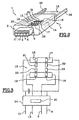
- the insertion part 4 is more particularly shown in FIG. 2. It has a connector 12, insertion means 13 of the module 5 as well as a protective shell 14 closed, at its end opposite the part of connection 2, by a plug 15.
- the connector 12 consists of a set of at least four legs curved and aligned.
- the connector 12 has eight metal tabs aligned in two rows of four legs. Four legs among the eight are electrically connected each with a connection line.
- a first tab 17 is connected to the first line 8
- a second leg 16 is connected to the second line 9
- a third leg 19 is connected to the third line 10
- a fourth leg 16 is connected to the fourth line 11.
- Lines 8 (GND) and 11 (Vbus) are interconnected by a decoupling capacity of the order of 100 nF.
- the other legs, i.e. the fifth 20, sixth 21, seventh 22 and eighth 23 legs are connected or not. If they are connected, they can be to an ISO / USB 24 protocol conversion element and / or to a clock element 25, for example, a quartz element, said elements being shown schematically in Figure 3.
- the insertion means 13 are in the form of a set of two opposite rebates 26 forming a slide for the insertion of the module 5 the along its edge. These rebates 26 direct the module 5 in the position of electrical connection to connector 12.
- the protective shell 14 is a plastic shell, for example molded, which covers the connector 12 and the insertion part 13.
- the plug 15, which closes this shell 14, is advantageously able to block the module 5 in inserted connection position in reader 1.
- this module 5 is consists of a plastic module body 27 in which is embedded a chip integrated circuit connected, by means of connection, to contact pads 28 flush with the surface of said module 5.
- the body of module 5 is in the form of a parallelepiped rectangle with dimensions of the following order: 25 mm in length, 15 mm wide and 0.76 mm thick. These dimensions, standardized, are defined in particular in appendix A of the ETSI / GSM 11.11 standard in its version 5.3.0 of July and 1996.
- the integrated circuit chip comprises different functional elements including RAM, ROM and EEPROM and a central processing unit CPU which manages, via bus data and addresses, generally confidential data.
- data are for example identification data of the module holder, public or private encryption keys, encryption algorithms, application programs, or passwords.
- the chip comprises at minus the following four contact pads: Vcc for the voltage supply of the chip, GND for grounding, D + and D- for data transmission according to the aforementioned USB standard.
- Other contact pads may be present, for example, the CLK pads for the input of a clock signal, I / O for the input and the data output according to protocols provided by ISO7816 and Vpp standards for programming voltage supply.
- the number and the position of the contact pads 28 of the module 5 are standardized in the aforementioned ISO7816 standard.
- the readers according to the invention which are devices compliant with the USB standard, do not include, with the exception of any elements 24 and 25, no electronics. Their manufacturing cost is therefore particularly low.
- a reader 1 When a user, who has acquired a reader 1 according to the invention for a low cost, and who has one or more personal computers with of ports 3 suitable for connection of said reader 1, wishes to use this reader 1, he must acquire an electronic module 5.
- a module 5 is generally marketed in the form of a card in the so-called ISO format, i.e. in the form of a substantially rectangular and rectangle map 29 whose length is around 85 mm, the width is around 54 mm and the thickness of the order of 0.76 mm, which includes a precut in the shape of the module 5.
- the user must then detach the module 5 from its card holder and insert it removably in the insertion part 13 of the reader 1. For this purpose, the user removes the plug 15 and inserts the module 5 along the rebates 26 forming a slide. Once inserted, the contact tabs of reader 1 come in contact with the contact pads 28 of the module which are there respectively associated. The user then closes the cap 15.
- a port 3 of a computer that is to say a port forming an integral part of the central processing unit of said computer or making part of a distributor connected by a cable to said central unit.
- a port is shown in Figures 4 and 5. It is a port described by the aforementioned USB standard. It includes a plastic end piece 30 comprising a connection part 31 in projection. Four tabs 32 for electrical connection are fixed to said part 31. Four blocking blades 33 are also fixed to the end piece 30. The connection is shown in Figure 6.
- this computer When the player is connected and the computer is turned on, this computer detects the presence of drive 1 and data can be exchanged between the chip of module 5 inserted in reader 1 and the computer, via the system USB bus.
- Data exchange protocols are described in the standard Aforementioned USB. The data exchange rates are, in accordance with this standard, 1.5 Mbit / s or 12 Mbit / s.
- programs can be executed securely in the chip to process data transmitted by the computer.
- algorithms present in the memories of the module chip can be used to encode data sent from the computer on the fly to to be transmitted over a network such as the Internet.
- the module can also include all passwords or user identification keys and the user just have to go and find them if necessary, in the secure memory of the module.
- these emails can be obtained using a mobile phone or, optionally, a personal computer.
Landscapes
- Engineering & Computer Science (AREA)
- Theoretical Computer Science (AREA)
- General Physics & Mathematics (AREA)
- Physics & Mathematics (AREA)
- Computer Hardware Design (AREA)
- Software Systems (AREA)
- General Engineering & Computer Science (AREA)
- Computer Security & Cryptography (AREA)
- Microelectronics & Electronic Packaging (AREA)
- Artificial Intelligence (AREA)
- Computer Vision & Pattern Recognition (AREA)
- Storage Device Security (AREA)
- Credit Cards Or The Like (AREA)
- Coupling Device And Connection With Printed Circuit (AREA)
- Communication Control (AREA)
Abstract
Description
L'invention concerne des lecteurs portatifs et, en particulier, des lecteurs portatifs de modules au format mini-carte tel que défini en annexe A de la norme ETSI/GSM 11.11 dans sa version 5.3.0 de juillet 1996.The invention relates to portable readers and in particular to portable readers. portable modules in mini-card format as defined in appendix A of the standard ETSI / GSM 11.11 in version 5.3.0 of July 1996.
De tels modules sont essentiellement utilisés en téléphonie mobile pour identifier leur porteur auprès d'un opérateur gestionnaire d'un réseau de télécommunications du type GSM (Global System for Mobile communications). Toutefois, ces modules sont en outre aptes à remplir de nombreuses autres fonctions. En effet, dans des développements récents, les modules comportent des programmes applicatifs, notamment rédigés dans des langages informatiques de haut niveau, qui leur permettent, dans le cadre d'une connexion à un réseau de télécommunications, d'assurer des transactions électroniques, d'assurer l'exécution de jeux voire même la mise en oeuvre de fonctions de messagerie. Bien entendu, compte tenu des faibles capacités mémoire et de vitesse de traitement de ces modules, ces programmes sont limités en taille mémoire et dans leur vitesse d'exécution. Toutefois, les modules sont sécurisés, portatifs et peu coûteux et présentent de ce fait un grand intérêt. EP - A - 883 083 décrit une mémoire "memory stick" ou la mémoire est mise en place de façon pas séparable. En effet, ce document ne décrit pas un lecteur. US 5 276 317 décrit un objet pour garder des modules SIM, par exemple associé à un porte-clés. Le document ne fait pas mention d'un lecteur à connexion électrique à un port d'un ordinateur.Such modules are mainly used in mobile telephony for identify their bearer with an operator managing a network of GSM type telecommunications (Global System for Mobile communications). However, these modules are also capable of fulfilling many other functions. Indeed, in recent developments, the modules include application programs, especially written in computer languages high-level, which allow them, as part of a connection to a network of telecommunications, ensuring electronic transactions, ensuring running games or even implementing messaging functions. Of course, given the low memory capacities and speed of processing of these modules, these programs are limited in memory size and in their speed of execution. However, the modules are secure, portable and little expensive and therefore of great interest. EP - A - 883 083 describes a memory "memory stick" where the memory is not installed separable. Indeed, this document does not describe a reader. US 5,276,317 describes an object for keeping SIM modules, for example associated with a key ring. Document does not mention a reader electrically connected to a port on a computer.
On sait que la sécurité des systèmes informatiques complexes n'est pas possible de manière simple. Lorsqu'un ordinateur du type ordinateur personnel est connecté à un réseau informatique, il est possible, à un tiers qui se serait introduit dans ce réseau, d'accéder frauduleusement à des données confidentielles mémorisées au sein dudit ordinateur et, si différentes solutions ont effectivement été envisagées pour une protection de ces données, aucune n'est complètement satisfaisante.We know that the security of complex computer systems is not possible in a simple way. When a personal computer type computer is connected to a computer network, it is possible, to a third party who introduced into this network, to fraudulently access confidential data stored in said computer and, if different solutions have actually have been considered for the protection of this data, none is completely satisfactory.
Par ailleurs, on sait que les utilisateurs de systèmes informatiques du type précité ont de plus en plus d'informations confidentielles personnelles à retenir et à gérer. Il s'agit, par exemple, de mots de passe les identifiant personnellement. Bien souvent, ces mots de passe sont changés périodiquement et il devient difficile, pour un utilisateur personne physique, de conserver, dans un endroit sécurisé, de nombreuses informations confidentielles personnelles.Furthermore, we know that users of computer systems of the type above have more and more personal confidential information to remember and to manage. For example, these are passwords that identify them personally. Often these passwords are changed periodically and it becomes difficult for a natural person user to keep in a place secure, lots of personal confidential information.
Enfin, on constate que de plus en plus de passerelles sont mises en place entre les différents réseaux. Notamment, de telles passerelles sont mises en place entre des réseaux informatiques internes à une société et des réseaux publics du type internet, ou même entre des réseaux de télécommunications et de tels réseaux publics. Aussi, il devient pratiquement possible d'accéder à un réseau second à partir d'un réseau premier via de telles passerelles et le besoin se fait sentir, pour un utilisateur d'une pluralité de réseaux, de disposer des données utiles à chacun desdits réseaux, quel que soit le point d'entrée choisi.Finally, we see that more and more gateways are being put in place between different networks. In particular, such gateways are implemented between a company's internal computer networks and public networks in the internet type, or even between telecommunications networks and such public networks. Also, it becomes practically possible to access a network second from a network first via such gateways and the need arises feel, for a user of a plurality of networks, to have the data useful to each of said networks, whatever the entry point chosen.
Compte tenu de ce qui précède, un problème que se propose de résoudre l'invention a trait à des moyens permettant une gestion pratique et entièrement sécurisée de données notamment personnelles destinées à être utilisées au sein de systèmes informatiques. La présente invention est telle que définie dans les revendications dont les préambules sont constitués par les caractéristiques décrites ci-dessus.In view of the above, a problem which we propose to solve the invention relates to means allowing practical and entirely management secure data, in particular personal data, intended for use within Informatic Systems. The present invention is as defined in the claims of which the preambles consist by the features described above.
Ainsi, le lecteur, dont les dimensions sont réduites, peut être connecté à un port adéquat d'un ordinateur, déconnecté de celui-ci et transporté avec son module et les données confidentielles qu'il comporte. Le module lui-même peut être retiré du lecteur et enfiché dans un autre dispositif par exemple un téléphone mobile où les données confidentielles qu'il comporte peuvent être utilisées.Thus, the reader, whose dimensions are reduced, can be connected to a adequate port of a computer, disconnected from it and transported with its module and the confidential data it contains. The module itself can be removed from the reader and plugged into another device such as a telephone mobile where the confidential data it contains can be used.
Par ailleurs, la solution proposée de l'invention au problème précité a pour second objet un procédé de gestion de données confidentielles mémorisées dans une mémoire sécurisée d'un module comprenant, d'une part, un corps de module plastique sensiblement parallélépipédique et rectangle dont les dimensions sont de l'ordre de 25 mm de longueur, 15 mm de largeur et 0,76 mm d'épaisseur et, d'autre part, une puce à circuit intégré munie de plots de contact connectés électriquement à des plages de contact affleurantes à l'une des faces dudit module, selon lequel :
- le module est inséré de manière amovible dans une partie d'insertion d'un lecteur portatif comportant une partie de connexion électrique à un port d'un ordinateur, ladite partie montrant quatre lignes conductrices, de manière que des pattes d'un connecteur de ladite partie d'insertion, qui sont électriquement connectées aux lignes conductrices, soient électriquement connectées aux plages de contact dudit module ;
- un utilisateur connecte le lecteur à un port d'un premier ordinateur ;
- des données sont échangées entre la puce du module et ledit premier ordinateur ;
- l'utilisateur déconnecte le lecteur du port du premier ordinateur ;
- l'utilisateur emporte le lecteur avec lui ;
- l'utilisateur connecteur le lecteur à un port d'un second ordinateur. Dans un premier mode de mise en oeuvre de ce procédé, le premier et le second ordinateur sont un seul et même ordinateur. Dans un second mode de mise en oeuvre, le premier ordinateur est différent du second ordinateur. D'autre part, de manière avantageuse, les données sont échangées via un système de bus USB et l'utilisateur retire le module du lecteur et l'insère dans un téléphone mobile.
- the module is removably inserted into an insertion part of a portable reader comprising a part for electrical connection to a port of a computer, said part showing four conductive lines, so that the tabs of a connector of said insertion part, which are electrically connected to the conductive lines, are electrically connected to the contact pads of said module;
- a user connects the reader to a port of a first computer;
- data is exchanged between the module chip and said first computer;
- the user disconnects the reader from the port of the first computer;
- the user takes the reader with him;
- the user connects the reader to a port on a second computer. In a first embodiment of this method, the first and the second computer are one and the same computer. In a second embodiment, the first computer is different from the second computer. On the other hand, advantageously, the data is exchanged via a USB bus system and the user removes the module from the reader and inserts it into a mobile phone.
La description qui va suivre, et qui ne présente aucun caractère limitatif,
permettra de mieux comprendre la manière dont l'invention peut être mise en
oeuvre. Elle est rédigée au regard des dessins annexés dans lesquels :
L'invention a trait à un lecteur 1 portatif.The invention relates to a
Un tel lecteur 1 a un poids de l'ordre de quelques grammes. Il s'inscrit dans
un parallélépipède rectangle dont les dimensions, longueur, largeur et épaisseur,
sont respectivement de l'ordre de 5, 3 et 2 cm. Aussi, un lecteur 1 selon
l'invention peut être associé à un porte-clés et/ou être transporté dans une poche
de son titulaire.Such a
Le lecteur 1 comporte une partie de connexion électrique 2 à un port 3 d'un
ordinateur personnel ou de tout autre matériel informatique de traitement de
données ainsi qu'une partie d'insertion 4 d'un module 5 électronique amovible.The
La partie de connexion électrique 2, plus particulièrement montrée aux
figures 1, 2, 5A et 5B, présente un embout 6 plastique de section rectangulaire
dont l'extrémité ouverte présente un élément 7 plastique de support à la surface
de laquelle affleurent quatre lignes métallisées parallèles, et quatre lignes
uniquement, formant un connecteur pour une connexion électrique du lecteur 1
au port 3. Ces lignes sont placées sensiblement à mi-hauteur dans l'embout 6.
Une première ligne 8 est destinée à une alimentation en courant Vbus du lecteur,
une seconde 9 et une troisième 10 lignes sont destinées à une communications de
données numériques audit lecteur 1 et une quatrième ligne 11 est destinée à une
mise à la masse de ce lecteur 1. Dans la norme USB (Universal Serial Bus),
version 1.1 du 23 septembre 1998, qui décrit une telle partie de connexion, et
dont le contenu est intégré à la présente description, par citation de référence, la
ligne 9 est une ligne D- et la ligne 10 est une ligne D+, D- et D+ désignant des
signaux de données définis dans ladite norme.The
La partie d'insertion 4 est plus particulièrement montrée à la figure 2. Elle
présente un connecteur 12, des moyens d'insertion 13 du module 5 ainsi qu'une
coque 14 de protection refermée, en son extrémité opposée à la partie de
connexion 2, par un bouchon 15.The insertion part 4 is more particularly shown in FIG. 2. It
has a
Le connecteur 12 se compose d'un ensemble d'au moins quatre pattes
recourbées et alignées. Dans l'exemple exposé dans la présente description, le
connecteur 12 comporte huit pattes métalliques alignées selon deux rangées de
quatre pattes. Quatre pattes parmi les huit sont connectées électriquement
chacune à une ligne de connexion. Une première patte 17 est connectée à la
première ligne 8, une seconde patte 16 est connectée à la seconde ligne 9, une
troisième patte 19 est connectée à la troisième ligne 10 et une quatrième patte 16
est connectée à la quatrième ligne 11. Les lignes 8 (GND) et 11 (Vbus) sont
connectées entre elles par une capacité de découplage de l'ordre de 100 nF. Les
autres pattes, c'est-à-dire les cinquième 20, sixième 21, septième 22 et huitième
23 pattes sont connectées ou non. Dans le cas où elles sont connectées, elles
peuvent l'être à un élément de conversion de protocole ISO/USB 24 et/ou à un
élément d'horloge 25, par exemple, un élément de quartz, lesdits éléments étant
schématisés à la figure 3.The
Les moyens d'insertion 13 se présentent sous la forme d'un ensemble de
deux feuillures 26 opposées formant une glissière pour l'insertion du module 5 le
long de sa tranche. Ces feuillures 26 dirigent le module 5 en position de
connexion électrique au connecteur 12.The insertion means 13 are in the form of a set of
two
La coque de protection 14 est une coque plastique, par exemple moulée, qui
recouvre le connecteur 12 et de la partie d'insertion 13. Le bouchon 15, qui
referme cette coque 14, est avantageusement apte à bloquer le module 5 en
position insérée de connexion dans le lecteur 1.The
Ainsi que cela est plus particulièrement montré à la figure 1, ce module 5 se
compose d'un corps de module 27 plastique dans lequel est noyé une puce à
circuit intégré connectée, par des moyens de connexion, à des plages de contact
28 affleurantes à la surface dudit module 5.As is more particularly shown in FIG. 1, this
Le corps du module 5 se présente sous la forme d'un parallélépipède
rectangle dont les dimensions sont de l'ordre des suivantes : 25 mm de longueur,
15 mm de largeur et 0,76 mm d'épaisseur. Ces dimensions, normalisées, sont
définies notamment en annexe A de la norme ETSI/GSM 11.11 dans sa version
5.3.0 de juillet et 1996.The body of
La puce à circuit intégré, non représentée sur les dessins, comporte différents élément fonctionnels dont des mémoires RAM, ROM et EEPROM et une unité centrale de traitement CPU qui gère, par l'intermédiaire de bus de données et d'adresses, des données généralement confidentielles. De telles données sont par exemple des données d'identification du titulaire du module, des clés publiques ou privées de cryptage, des algorithmes de codage, des programmes applicatifs, ou des mots de passe. Par ailleurs, la puce comporte au moins les quatre plots de contact suivants : Vcc pour l'alimentation en tension de la puce, GND pour la mise à la masse, D+ et D- pour la transmission des données selon la norme précitée USB. D'autres plots de contact peuvent être présents, par exemple, les plots CLK pour l'entrée d'un signal d'horloge, I/O pour l'entrée et la sortie des données selon les protocoles prévus par les normes ISO7816 et Vpp pour l'alimentation en tension de programmation.The integrated circuit chip, not shown in the drawings, comprises different functional elements including RAM, ROM and EEPROM and a central processing unit CPU which manages, via bus data and addresses, generally confidential data. Such data are for example identification data of the module holder, public or private encryption keys, encryption algorithms, application programs, or passwords. Furthermore, the chip comprises at minus the following four contact pads: Vcc for the voltage supply of the chip, GND for grounding, D + and D- for data transmission according to the aforementioned USB standard. Other contact pads may be present, for example, the CLK pads for the input of a clock signal, I / O for the input and the data output according to protocols provided by ISO7816 and Vpp standards for programming voltage supply.
Le nombre et la position des plages de contact 28 du module 5 sont
normalisés dans la norme ISO7816 précitée.The number and the position of the
En définitive, les lecteurs selon l'invention, qui sont des dispositifs
conformes à la norme USB, ne comportent, à l'exception des éléments éventuels
24 et 25, aucune électronique. Leur coût de fabrication est donc particulièrement
faible.Ultimately, the readers according to the invention, which are devices
compliant with the USB standard, do not include, with the exception of any
Lorsqu'un utilisateur, qui a acquis un lecteur 1 selon l'invention pour un
coût modique, et qui dispose d'un ou de plusieurs ordinateurs personnels munis
de ports 3 adéquats pour une connexion dudit lecteur 1, souhaite utiliser ce
lecteur 1, il doit acquérir un module 5 électronique. Un tel module 5 est
généralement commercialisé sous la forme d'une carte au format dit ISO, c'est-à-dire
sous la forme d'une carte 29 sensiblement parallélépipédique et rectangle
dont la longueur est de l'ordre de 85 mm, la largeur est de l'ordre de 54 mm et
l'épaisseur de l'ordre de 0,76 mm, qui comporte une prédécoupe à la forme du
module 5.When a user, who has acquired a
L'utilisateur doit alors détacher le module 5 de son support carte et l'insérer
de manière amovible dans la partie d'insertion 13 du lecteur 1. A cet effet,
l'utilisateur retire le bouchon 15 et insère le module 5 le long des feuillures 26
formant une glissière. Une fois inséré, les pattes de contact du lecteur 1 viennent
au contact des plages de contact 28 du module qui leur sont respectivement
associées. L'utilisateur referme alors le bouchon 15.The user must then detach the
Puis, l'utilisateur connecte le lecteur à un port 3 d'un ordinateur, c'est-à-dire
un port faisant partie intégrante de l'unité centrale dudit ordinateur ou faisant
partie d'un répartiteur connecté, par un câble, à ladite unité centrale. Un tel port
est montré aux figures 4 et 5. Il s'agit d'un port décrit par la norme USB précitée.
Il comporte un embout 30 plastique comprenant une partie 31 de connexion en
saillie. Quatre pattes 32 de connexion électrique sont fixées à ladite partie 31.
Quatre lames 33 de blocage sont par ailleurs fixées à l'embout 30. La connexion
est montrée à la figure 6.Then, the user connects the reader to a port 3 of a computer, that is to say
a port forming an integral part of the central processing unit of said computer or making
part of a distributor connected by a cable to said central unit. Such a port
is shown in Figures 4 and 5. It is a port described by the aforementioned USB standard.
It includes a
Lorsque le lecteur est connecté et que l'ordinateur est sous tension, cet
ordinateur détecte la présence du lecteur 1 et des données peuvent être échangées
entre la puce du module 5 inséré dans le lecteur 1 et l'ordinateur, via le système
de bus USB. Les protocoles d'échange de données sont décrits dans la norme
USB précitée. Les débits des données échangées sont, conformément à cette
norme, de 1,5 Mbit/s ou de 12 Mbit/s.When the player is connected and the computer is turned on, this
computer detects the presence of
Aussi, des programmes peuvent être exécutés de manière sécurisée dans la puce en vue de traiter des données transmises par l'ordinateur. Par exemple, des algorithmes présents dans les mémoires de la puce du module peuvent être utilisés pour coder des données à la volée transmises par l'ordinateur et destinées à être transmises sur un réseau tel que l'internet. Le module peut par ailleurs comporter tous les mots de passe ou clés d'identification de l'utilisateur et celui ci n'a plus qu'à aller les chercher si besoin, dans la mémoire sécurisée du module.Also, programs can be executed securely in the chip to process data transmitted by the computer. For example, algorithms present in the memories of the module chip can be used to encode data sent from the computer on the fly to to be transmitted over a network such as the Internet. The module can also include all passwords or user identification keys and the user just have to go and find them if necessary, in the secure memory of the module.
Si l'utilisateur ne souhaite plus se servir de l'ordinateur, il peut déconnecter le lecteur et l'emporter avec lui. Si l'utilisateur, veut se servir de ses mots de passe ou autres informations confidentielles à partir d'un autre ordinateur, il suffit qu'il connecte le lecteur de l'invention, à cet autre ordinateur.If the user no longer wishes to use the computer, he can disconnect the reader and take it with him. If the user wants to use his password or other confidential information from another computer it it suffices that he connects the reader of the invention to this other computer.
Il peut par ailleurs retirer le module du lecteur et l'insérer par exemple, dans son téléphone mobile, pour une utilisation des données dudit module, avec ledit téléphone. Ainsi, dans le cas où des données de la mémoire du module sont destinées à la mémorisation de courriers électroniques, ces courriers peuvent être obtenus au moyen d'un téléphone mobile ou, au choix, d'un ordinateur personnel.He can also remove the module from the reader and insert it, for example, in his mobile phone, for using the data from said module, with said phone. Thus, in the case where data from the module memory is intended for the storage of electronic mails, these emails can be obtained using a mobile phone or, optionally, a personal computer.
Claims (9)
- A portable reader (1), characterized in that the portable reader comprises four electrical connection lines (8, 9, 10, 11) to be electrically connected to a computer port (3), as well as a portion (4) for inserting a module (5) arranged to store confidential information, the module comprising, on the one hand, a plastic module body (27) having a substantially parallelepipedal rectangular shape with dimensions of the order of 25 mm in length, 15 mm in width and 0.76 mm in thickness and, on the other hand, an integrated circuit chip provided with contact terminals electrically connected to contact pads (28) that are flush with one of the faces of said module (5), said portion (4) of the portable reader (1) comprising pads that are electrically connected to the four electrical connection lines (8, 9, 10, 11) of the reader (1) and, when the module (5) is inserted into said portable reader (1), to the contact pads (28) of said module (5).
- Reader (1) according to claim 1, characterized in that the reader is inscribed within a rectangular parallelepiped having length, width and height dimensions, of about 5, 3 and 2 cm, respectively.
- Reader (1) according to claim 1, characterized in that the reader constitutes a device according to the USB standard.
- Reader (1) according to claim 1, characterized in that the reader is combined with a key ring.
- Method of managing confidential data stored within a secure memory of a module 5, comprising, on the one hand, a plastic module body (27) of substantially parallelepipedal and rectangular shape, the dimensions of which are about 25 mm in length, 15 mm in width and 0.76 mm in thickness and, on the other hand, an integrated circuit chip provided with contact terminals electrically connected to contact pads (28) that are flush with one of the faces of said module (5), in which:the module (5) is inserted into a portion (4) of a portable reader (1) that comprises four electrical connection lines (8, 9, 10, 11) to be electrically connected to a computer port (3), the module being inserted so that said contact pads of the module are electrically connected to pads in said portion of the portable reader, the pads being electrically connected to the four electrical connection lines of the portable reader;a user connects the reader (1) to a port (3) of a first computer;data are exchanged between the integrated circuit chip located in the module (5) and the first computer;the user disconnects the reader (1) from the port (3) of the first computer;the user takes the reader (1) with him/her;the user connects the reader (1) to a port (3) of a second computer.
- Method according to claim 5, characterized in that the first and second computers are one and the same computer.
- Method according to claim 5, characterized in that the first computer is different from the second computer.
- Method according to claim 5, characterized in that the data are exchanged via a USB bus system.
- Method according to claim 5, characterized in that the user withdraws the module (5) from the reader (1) and inserts it into a mobile phone.
Applications Claiming Priority (3)
| Application Number | Priority Date | Filing Date | Title |
|---|---|---|---|
| FR9906122 | 1999-05-12 | ||
| FR9906122A FR2793575B1 (en) | 1999-05-12 | 1999-05-12 | PORTABLE MINI-CARD MODULE READER FOR CONNECTION TO A PORT OF A PERSONAL COMPUTER |
| PCT/FR2000/001300 WO2000070533A1 (en) | 1999-05-12 | 2000-05-12 | Portable mini-card sized module reader for connection to the port of a personal computer |
Publications (2)
| Publication Number | Publication Date |
|---|---|
| EP1181663A1 EP1181663A1 (en) | 2002-02-27 |
| EP1181663B1 true EP1181663B1 (en) | 2003-03-12 |
Family
ID=9545557
Family Applications (1)
| Application Number | Title | Priority Date | Filing Date |
|---|---|---|---|
| EP00927338A Expired - Lifetime EP1181663B1 (en) | 1999-05-12 | 2000-05-12 | Portable mini-card sized module reader for connection to the port of a personal computer |
Country Status (9)
| Country | Link |
|---|---|
| US (1) | US6715678B1 (en) |
| EP (1) | EP1181663B1 (en) |
| CN (2) | CN101162494A (en) |
| AT (1) | ATE234486T1 (en) |
| DE (1) | DE60001650T2 (en) |
| DK (1) | DK1181663T3 (en) |
| ES (1) | ES2194724T3 (en) |
| FR (1) | FR2793575B1 (en) |
| WO (1) | WO2000070533A1 (en) |
Families Citing this family (17)
| Publication number | Priority date | Publication date | Assignee | Title |
|---|---|---|---|---|
| AT501651B1 (en) * | 2000-09-27 | 2007-02-15 | Omnikey Gmbh | ELECTRONIC MODULE WITH A CONNECTOR TO A HIGH-ORDERED UNIT |
| US6435409B1 (en) * | 2001-03-23 | 2002-08-20 | Kuang-Hua Hu | Card reader structure with an axial-rotate joint |
| US20020177362A1 (en) * | 2001-05-23 | 2002-11-28 | Chang Ting Chen | Portable memory storage-retrieval device |
| FR2825170B1 (en) * | 2001-05-25 | 2005-02-11 | Xiring | ELECTRONIC MODULE CONNECTABLE ON A PORT OF A COMPUTER |
| JP2006517327A (en) * | 2002-10-11 | 2006-07-20 | アクサルト ソシエテ アノニム | Portable reader |
| GB2396707B (en) * | 2002-10-17 | 2004-11-24 | Vodafone Plc | Facilitating and authenticating transactions |
| GB2394327B (en) * | 2002-10-17 | 2006-08-02 | Vodafone Plc | Device for facilitating and authenticating transactions |
| JP4509930B2 (en) | 2002-10-17 | 2010-07-21 | ヴォウダフォン・グループ・ピーエルシー | Facilitating and authenticating transactions |
| TWM259987U (en) * | 2004-04-09 | 2005-03-21 | Yi-Ming Chen | Memory card portable disk |
| US20050247796A1 (en) * | 2004-05-05 | 2005-11-10 | Chen I M | Memory-card type USB mass storage device |
| HK1063994A2 (en) * | 2004-06-09 | 2004-12-17 | 龙杰智能卡有限公司 | Smart card reader with contactless access capability |
| US8061623B2 (en) * | 2006-02-09 | 2011-11-22 | Vadim Evgenevich Balchaytis | Plastic card provided with electrical contacts |
| CN101366050B (en) | 2006-02-09 | 2012-06-13 | 瓦季姆·叶夫根尼耶维奇·巴尔查蒂斯 | Plastic card with electrical contacts |
| US20070235519A1 (en) * | 2006-04-05 | 2007-10-11 | Samsung Electronics Co., Ltd. | Multi-functional dongle for a portable terminal |
| FR2903514B1 (en) * | 2006-07-04 | 2008-10-17 | Oberthur Card Syst Sa | HOUSING FOR ELECTRONIC KEY AND SYSTEM COMPRISING SUCH A HOUSING |
| WO2008029206A2 (en) * | 2006-09-05 | 2008-03-13 | Nokia Corporation | Device interface |
| CN202004207U (en) * | 2011-02-25 | 2011-10-05 | 华为终端有限公司 | Connector and wireless modulator demodulator |
Family Cites Families (5)
| Publication number | Priority date | Publication date | Assignee | Title |
|---|---|---|---|---|
| US2802188A (en) * | 1955-11-21 | 1957-08-06 | Bell Telephone Labor Inc | Electrical socket connector for printed circuit boards |
| FR2665556A1 (en) * | 1990-08-03 | 1992-02-07 | Alcatel Radiotelephone | MEMORY CARD HOUSING DEVICE. |
| US5887145A (en) * | 1993-09-01 | 1999-03-23 | Sandisk Corporation | Removable mother/daughter peripheral card |
| EP0830000A2 (en) | 1996-09-11 | 1998-03-18 | Hewlett-Packard Company | Apparatus and method for connecting portable phone to portable image capture device |
| JP3104646B2 (en) * | 1997-06-04 | 2000-10-30 | ソニー株式会社 | External storage device |
-
1999
- 1999-05-12 FR FR9906122A patent/FR2793575B1/en not_active Expired - Fee Related
-
2000
- 2000-05-12 US US10/009,706 patent/US6715678B1/en not_active Expired - Lifetime
- 2000-05-12 WO PCT/FR2000/001300 patent/WO2000070533A1/en not_active Ceased
- 2000-05-12 DK DK00927338T patent/DK1181663T3/en active
- 2000-05-12 AT AT00927338T patent/ATE234486T1/en not_active IP Right Cessation
- 2000-05-12 ES ES00927338T patent/ES2194724T3/en not_active Expired - Lifetime
- 2000-05-12 DE DE60001650T patent/DE60001650T2/en not_active Expired - Lifetime
- 2000-05-12 EP EP00927338A patent/EP1181663B1/en not_active Expired - Lifetime
- 2000-05-12 CN CNA200710149060XA patent/CN101162494A/en active Pending
- 2000-05-12 CN CN00809086A patent/CN1357130A/en active Pending
Also Published As
| Publication number | Publication date |
|---|---|
| ES2194724T3 (en) | 2003-12-01 |
| CN1357130A (en) | 2002-07-03 |
| WO2000070533A1 (en) | 2000-11-23 |
| DE60001650T2 (en) | 2003-12-18 |
| CN101162494A (en) | 2008-04-16 |
| FR2793575B1 (en) | 2001-06-15 |
| FR2793575A1 (en) | 2000-11-17 |
| DK1181663T3 (en) | 2003-07-14 |
| ATE234486T1 (en) | 2003-03-15 |
| EP1181663A1 (en) | 2002-02-27 |
| US6715678B1 (en) | 2004-04-06 |
| DE60001650D1 (en) | 2003-04-17 |
Similar Documents
| Publication | Publication Date | Title |
|---|---|---|
| EP1181663B1 (en) | Portable mini-card sized module reader for connection to the port of a personal computer | |
| EP1433125B1 (en) | Dongle which is intended to be connected to a port of a telecommunications device | |
| EP0696010B2 (en) | Portable interface for electronic chip card | |
| FR2710996A1 (en) | Multi-application portable card for personal computer. | |
| EP1110173B1 (en) | Data transmission method and card therefor | |
| EP0552078B1 (en) | Insertable card for microcomputer constituting a reader for cards with flat contacts | |
| WO2008003586A1 (en) | Casing for electronic key and system comprising such a casing | |
| EP0840247B1 (en) | Radio modem equipped with a memory card reader | |
| CA2212951C (en) | Connector for an apparatus for reading smart cards | |
| FR2804224A1 (en) | IC card interface device for entering data into portable terminal; uses communication protocols in communication between card interface and portable device | |
| EP1317732B1 (en) | Multiport card | |
| EP2239691A1 (en) | Unit with USB key including a chip card | |
| FR2948794A1 (en) | Microcircuit card i.e. identification card, for use in mobile network, has two external contact interfaces defining two surfaces formed on body, so that surfaces coincide partially along vertical direction | |
| EP2649777B1 (en) | Electronic payment device | |
| FR2722589A1 (en) | Portable interface for card with embedded electronic circuit | |
| WO1998053421A1 (en) | Connector with direct or indirect insertion of smart card therein | |
| WO2000019368A1 (en) | Card with detachable module | |
| EP1045338B1 (en) | Electronic memory card with card security element | |
| WO1999038105A1 (en) | Connector or fitting in the form of a smart card | |
| EP1556833B2 (en) | Set of microcircuit cards precut in a common plastic support and comprising complementary functions | |
| WO2002101641A1 (en) | Detachable chip card on support with pre-cut portion | |
| FR2976376A1 (en) | USB ASSEMBLY WITH IMPROVED USB KEY | |
| FR2910151A1 (en) | Rectangular shaped electronic chip device manufacturing method for electronic chip reading system, involves inserting micro module in thickness of part so that introduction of part establishes electrical connections between contacts | |
| FR2893437A1 (en) | ELECTRONIC KEY COMPRISING USB AND NON-CONTACT COMMUNICATION MEANS AND METHOD OF MANUFACTURING THE SAME | |
| EP1199625A1 (en) | Method and secure terminal for chipcard authentication |
Legal Events
| Date | Code | Title | Description |
|---|---|---|---|
| PUAI | Public reference made under article 153(3) epc to a published international application that has entered the european phase |
Free format text: ORIGINAL CODE: 0009012 |
|
| 17P | Request for examination filed |
Effective date: 20011130 |
|
| AK | Designated contracting states |
Kind code of ref document: A1 Designated state(s): AT BE CH CY DE DK ES FI FR GB GR IE IT LI LU MC NL PT SE |
|
| AX | Request for extension of the european patent |
Free format text: AL;LT;LV;MK;RO;SI |
|
| 17Q | First examination report despatched |
Effective date: 20020304 |
|
| GRAH | Despatch of communication of intention to grant a patent |
Free format text: ORIGINAL CODE: EPIDOS IGRA |
|
| GRAH | Despatch of communication of intention to grant a patent |
Free format text: ORIGINAL CODE: EPIDOS IGRA |
|
| GRAA | (expected) grant |
Free format text: ORIGINAL CODE: 0009210 |
|
| AK | Designated contracting states |
Designated state(s): AT BE CH CY DE DK ES FI FR GB GR IE IT LI LU MC NL PT SE |
|
| PG25 | Lapsed in a contracting state [announced via postgrant information from national office to epo] |
Ref country code: GR Free format text: LAPSE BECAUSE OF FAILURE TO SUBMIT A TRANSLATION OF THE DESCRIPTION OR TO PAY THE FEE WITHIN THE PRESCRIBED TIME-LIMIT Effective date: 20030312 Ref country code: AT Free format text: LAPSE BECAUSE OF FAILURE TO SUBMIT A TRANSLATION OF THE DESCRIPTION OR TO PAY THE FEE WITHIN THE PRESCRIBED TIME-LIMIT Effective date: 20030312 Ref country code: IE Free format text: LAPSE BECAUSE OF FAILURE TO SUBMIT A TRANSLATION OF THE DESCRIPTION OR TO PAY THE FEE WITHIN THE PRESCRIBED TIME-LIMIT Effective date: 20030312 |
|
| REG | Reference to a national code |
Ref country code: GB Ref legal event code: FG4D Free format text: NOT ENGLISH |
|
| REG | Reference to a national code |
Ref country code: CH Ref legal event code: EP |
|
| REG | Reference to a national code |
Ref country code: IE Ref legal event code: FG4D Free format text: FRENCH |
|
| REF | Corresponds to: |
Ref document number: 60001650 Country of ref document: DE Date of ref document: 20030417 Kind code of ref document: P |
|
| PG25 | Lapsed in a contracting state [announced via postgrant information from national office to epo] |
Ref country code: LU Free format text: LAPSE BECAUSE OF NON-PAYMENT OF DUE FEES Effective date: 20030512 Ref country code: CY Free format text: LAPSE BECAUSE OF FAILURE TO SUBMIT A TRANSLATION OF THE DESCRIPTION OR TO PAY THE FEE WITHIN THE PRESCRIBED TIME-LIMIT Effective date: 20030512 |
|
| PG25 | Lapsed in a contracting state [announced via postgrant information from national office to epo] |
Ref country code: BE Free format text: LAPSE BECAUSE OF NON-PAYMENT OF DUE FEES Effective date: 20030531 Ref country code: MC Free format text: LAPSE BECAUSE OF NON-PAYMENT OF DUE FEES Effective date: 20030531 |
|
| PG25 | Lapsed in a contracting state [announced via postgrant information from national office to epo] |
Ref country code: PT Free format text: LAPSE BECAUSE OF FAILURE TO SUBMIT A TRANSLATION OF THE DESCRIPTION OR TO PAY THE FEE WITHIN THE PRESCRIBED TIME-LIMIT Effective date: 20030616 |
|
| REG | Reference to a national code |
Ref country code: SE Ref legal event code: TRGR |
|
| GBT | Gb: translation of ep patent filed (gb section 77(6)(a)/1977) | ||
| REG | Reference to a national code |
Ref country code: DK Ref legal event code: T3 |
|
| LTIE | Lt: invalidation of european patent or patent extension |
Effective date: 20030312 |
|
| REG | Reference to a national code |
Ref country code: IE Ref legal event code: FD4D Ref document number: 1181663E Country of ref document: IE |
|
| BERE | Be: lapsed |
Owner name: *SCHLUMBERGER SYSTEMES Effective date: 20030531 |
|
| PLBE | No opposition filed within time limit |
Free format text: ORIGINAL CODE: 0009261 |
|
| STAA | Information on the status of an ep patent application or granted ep patent |
Free format text: STATUS: NO OPPOSITION FILED WITHIN TIME LIMIT |
|
| 26N | No opposition filed |
Effective date: 20031215 |
|
| PG25 | Lapsed in a contracting state [announced via postgrant information from national office to epo] |
Ref country code: CH Free format text: LAPSE BECAUSE OF NON-PAYMENT OF DUE FEES Effective date: 20040531 Ref country code: LI Free format text: LAPSE BECAUSE OF NON-PAYMENT OF DUE FEES Effective date: 20040531 |
|
| REG | Reference to a national code |
Ref country code: CH Ref legal event code: PL |
|
| NLT1 | Nl: modifications of names registered in virtue of documents presented to the patent office pursuant to art. 16 a, paragraph 1 |
Owner name: AXALTO S.A. |
|
| REG | Reference to a national code |
Ref country code: FR Ref legal event code: CD Ref country code: FR Ref legal event code: CA |
|
| REG | Reference to a national code |
Ref country code: DE Ref legal event code: R082 Ref document number: 60001650 Country of ref document: DE |
|
| REG | Reference to a national code |
Ref country code: DE Ref legal event code: R081 Ref document number: 60001650 Country of ref document: DE Owner name: GEMALTO SA, FR Free format text: FORMER OWNER: AXALTO S.A., MONTROUGE, FR Effective date: 20111013 |
|
| PGFP | Annual fee paid to national office [announced via postgrant information from national office to epo] |
Ref country code: DK Payment date: 20130424 Year of fee payment: 14 Ref country code: GB Payment date: 20130424 Year of fee payment: 14 Ref country code: SE Payment date: 20130425 Year of fee payment: 14 |
|
| PGFP | Annual fee paid to national office [announced via postgrant information from national office to epo] |
Ref country code: FI Payment date: 20130423 Year of fee payment: 14 Ref country code: IT Payment date: 20130424 Year of fee payment: 14 Ref country code: NL Payment date: 20130424 Year of fee payment: 14 |
|
| REG | Reference to a national code |
Ref country code: NL Ref legal event code: V1 Effective date: 20141201 |
|
| REG | Reference to a national code |
Ref country code: DK Ref legal event code: EBP Effective date: 20140531 |
|
| GBPC | Gb: european patent ceased through non-payment of renewal fee |
Effective date: 20140512 |
|
| PG25 | Lapsed in a contracting state [announced via postgrant information from national office to epo] |
Ref country code: FI Free format text: LAPSE BECAUSE OF NON-PAYMENT OF DUE FEES Effective date: 20140512 Ref country code: SE Free format text: LAPSE BECAUSE OF NON-PAYMENT OF DUE FEES Effective date: 20140513 |
|
| REG | Reference to a national code |
Ref country code: SE Ref legal event code: EUG |
|
| PG25 | Lapsed in a contracting state [announced via postgrant information from national office to epo] |
Ref country code: NL Free format text: LAPSE BECAUSE OF NON-PAYMENT OF DUE FEES Effective date: 20141201 |
|
| PG25 | Lapsed in a contracting state [announced via postgrant information from national office to epo] |
Ref country code: IT Free format text: LAPSE BECAUSE OF NON-PAYMENT OF DUE FEES Effective date: 20140512 Ref country code: DK Free format text: LAPSE BECAUSE OF NON-PAYMENT OF DUE FEES Effective date: 20140531 |
|
| PG25 | Lapsed in a contracting state [announced via postgrant information from national office to epo] |
Ref country code: GB Free format text: LAPSE BECAUSE OF NON-PAYMENT OF DUE FEES Effective date: 20140512 |
|
| REG | Reference to a national code |
Ref country code: FR Ref legal event code: PLFP Year of fee payment: 17 |
|
| REG | Reference to a national code |
Ref country code: FR Ref legal event code: PLFP Year of fee payment: 18 |
|
| REG | Reference to a national code |
Ref country code: FR Ref legal event code: PLFP Year of fee payment: 19 |
|
| PGFP | Annual fee paid to national office [announced via postgrant information from national office to epo] |
Ref country code: DE Payment date: 20190418 Year of fee payment: 20 Ref country code: ES Payment date: 20190603 Year of fee payment: 20 |
|
| PGFP | Annual fee paid to national office [announced via postgrant information from national office to epo] |
Ref country code: FR Payment date: 20190418 Year of fee payment: 20 |
|
| REG | Reference to a national code |
Ref country code: DE Ref legal event code: R071 Ref document number: 60001650 Country of ref document: DE |
|
| REG | Reference to a national code |
Ref country code: ES Ref legal event code: FD2A Effective date: 20200826 |
|
| PG25 | Lapsed in a contracting state [announced via postgrant information from national office to epo] |
Ref country code: ES Free format text: LAPSE BECAUSE OF EXPIRATION OF PROTECTION Effective date: 20200513 |