EP1180853A1 - Method and apparatus for automatic frequency control and demodulator - Google Patents
Method and apparatus for automatic frequency control and demodulator Download PDFInfo
- Publication number
- EP1180853A1 EP1180853A1 EP00913061A EP00913061A EP1180853A1 EP 1180853 A1 EP1180853 A1 EP 1180853A1 EP 00913061 A EP00913061 A EP 00913061A EP 00913061 A EP00913061 A EP 00913061A EP 1180853 A1 EP1180853 A1 EP 1180853A1
- Authority
- EP
- European Patent Office
- Prior art keywords
- frequency
- frequency offset
- signal
- radio receiving
- receiving signal
- Prior art date
- Legal status (The legal status is an assumption and is not a legal conclusion. Google has not performed a legal analysis and makes no representation as to the accuracy of the status listed.)
- Withdrawn
Links
Images








Classifications
-
- H—ELECTRICITY
- H03—ELECTRONIC CIRCUITRY
- H03J—TUNING RESONANT CIRCUITS; SELECTING RESONANT CIRCUITS
- H03J7/00—Automatic frequency control; Automatic scanning over a band of frequencies
- H03J7/02—Automatic frequency control
-
- H—ELECTRICITY
- H04—ELECTRIC COMMUNICATION TECHNIQUE
- H04B—TRANSMISSION
- H04B7/00—Radio transmission systems, i.e. using radiation field
- H04B7/01—Reducing phase shift
-
- H—ELECTRICITY
- H04—ELECTRIC COMMUNICATION TECHNIQUE
- H04L—TRANSMISSION OF DIGITAL INFORMATION, e.g. TELEGRAPHIC COMMUNICATION
- H04L27/00—Modulated-carrier systems
- H04L27/18—Phase-modulated carrier systems, i.e. using phase-shift keying
- H04L27/22—Demodulator circuits; Receiver circuits
- H04L27/233—Demodulator circuits; Receiver circuits using non-coherent demodulation
- H04L27/2332—Demodulator circuits; Receiver circuits using non-coherent demodulation using a non-coherent carrier
-
- H—ELECTRICITY
- H04—ELECTRIC COMMUNICATION TECHNIQUE
- H04L—TRANSMISSION OF DIGITAL INFORMATION, e.g. TELEGRAPHIC COMMUNICATION
- H04L27/00—Modulated-carrier systems
- H04L27/0014—Carrier regulation
- H04L2027/0024—Carrier regulation at the receiver end
- H04L2027/0026—Correction of carrier offset
- H04L2027/003—Correction of carrier offset at baseband only
-
- H—ELECTRICITY
- H04—ELECTRIC COMMUNICATION TECHNIQUE
- H04L—TRANSMISSION OF DIGITAL INFORMATION, e.g. TELEGRAPHIC COMMUNICATION
- H04L27/00—Modulated-carrier systems
- H04L27/0014—Carrier regulation
- H04L2027/0044—Control loops for carrier regulation
- H04L2027/0063—Elements of loops
- H04L2027/0065—Frequency error detectors
-
- H—ELECTRICITY
- H04—ELECTRIC COMMUNICATION TECHNIQUE
- H04L—TRANSMISSION OF DIGITAL INFORMATION, e.g. TELEGRAPHIC COMMUNICATION
- H04L27/00—Modulated-carrier systems
- H04L27/0014—Carrier regulation
- H04L2027/0083—Signalling arrangements
- H04L2027/0089—In-band signals
- H04L2027/0093—Intermittant signals
-
- H—ELECTRICITY
- H04—ELECTRIC COMMUNICATION TECHNIQUE
- H04L—TRANSMISSION OF DIGITAL INFORMATION, e.g. TELEGRAPHIC COMMUNICATION
- H04L27/00—Modulated-carrier systems
- H04L27/0014—Carrier regulation
- H04L2027/0083—Signalling arrangements
- H04L2027/0089—In-band signals
- H04L2027/0093—Intermittant signals
- H04L2027/0095—Intermittant signals in a preamble or similar structure
Definitions
- the present invention relates to an automatic frequency control method and device, which are applied to digital demodulation processing in satellite communication, mobile satellite communication, mobile terrestrial communication, and a demodulator to which said device is applied.
- a technique for compensating frequency offset is disclosed in, for example, Japanese Patent Laid-Open No. 93302/1997 titled "DIGITAL MOBILE RADIO COMMUNICATION METHOD" .
- frequency offset is eliminated by using phase fluctuation information of known signals (pilot signals).
- the phase change amount between the sequential two-symbol known signals is supposed as frequency offset.
- the frequency offset calculated in this case is equivalent to the difference between the oscillation frequency f o at the receiver side and the frequency f D of the direct wave. That is, in the prior art, as shown in Fig. 24B, frequency control is carried out so that the frequency f D of the direct wave almost coincides with the oscillation frequency f o . In this case, the center frequency f M of the Doppler spread deviates from the oscillation frequency f o by the Doppler-shift amount f DP .
- the Doppler spread apparently further broadens, so that the frequency corresponding to the end of the Doppler spread greatly deviates from the oscillation frequency f o . Accordingly, frequency offset cannot be satisfactorily compensated. Therefore, bit error rate characteristics (hereinafter, referred to as BER characteristics) after the radio receiving signal is demodulated may deteriorate.
- BER characteristics bit error rate characteristics
- the object of the invention is therefore to solve the abovementioned technical problems and provide an automatic frequency control method and device by which satisfactory BER characteristics can be realized without being influenced by a Doppler-shifted direct wave in a Rician fading environment where the direct wave has Doppler-shifted.
- Another object of the invention is to provide a demodulator by which demodulation accuracy can be improved by applying the abovementioned automatic frequency control device to this demodulator.
- an automatic frequency control method of the invention which controls the frequency of a radio receiving signal by compensating frequency offset of the radio receiving signal that periodically includes a plurality of adjacent known signals, comprising, based on the distortion amount of each known signal included in the radio receiving signal, the frequency of the direct wave of the radio receiving signal and the center frequency of the Doppler spread of the radio receiving signal are estimated, and based on both of the frequencies, frequency offset of the radio receiving signal is compensated.
- the compensating range of frequency offset can be sufficiently secured, and by compensating the frequency offset based on the center frequency of the Doppler spread, satisfactory BER characteristics can be secured. That is, compatibility with securing of a sufficient frequency offset compensating range and securing of satisfactory BER characteristics can be realized.
- the abovementioned construction is applied to a demodulator, whereby demodulation processing can be executed for a radio receiving signal in which frequency offset has been satisfactorily eliminated. Therefore, the demodulation quality can be improved.
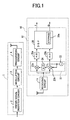
- Fig. 1 is a block diagram showing the construction of a radio communication system to which an automatic frequency control method relating to Embodiment 1 of the invention is applied.
- This radio communication system comprises transmitter 1 and receiver 10, and has a function for estimating and eliminating frequency offset of a burst signal radio-transmitted from the transmitter 1 by receiver 10.
- a satellite communication system for this radio communication system, a satellite communication system, mobile satellite communication system, and mobile terrestrial communication system can be applied.
- transmitter 1 and receiver 10 are applied to earth stations set at different positions on the earth.
- the transmitter 1 is applied to either an earth station or a mobile station that is set on the earth, and the receiver 10 is applied to an opposite station of the transmitter 1 of the two stations.
- the transmitter 1 is applied to either a base station or a mobile station, and the receiver 10 is applied to an opposite station of the transmitter 1 of the two stations.
- a satellite mobile phone of a single mode or a dual mode can be applied.
- a cellular phone can be applied to the mobile station in the mobile terrestrial communication system.
- This communication system uses the TDMA (Time Division Multiple Access) as a communication method. Therefore, the transmitter 1 radio-transmits a burst signal synchronized with a predetermined time slot to the receiver 10.
- the receiver 10 demodulates the receiving burst signal, eliminates frequency offset, and then restores the original signal.
- the transmitter 1 comprises known signal insertion circuit 2, modulation circuit 3, and transmission circuit 4.
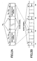
- the known signal insertion circuit 2 periodically inserts known signals into information signals to be transmitted, and generates burst signals before modulation. Concretely, as shown in Fig. 2A, the known signal insertion circuit 2 inserts N P -symbol sequential known signal rows (hereinafter, referred to as known signal blocks) into (N F -N P )-symbol information at every N F -symbol periods.
- N P is an integer of 2 or more (N P ⁇ 2).
- the timings at which the known signals are inserted are shown by (kN F +i)T S .
- k indicates the insertion order of the known signals.
- i is a value between zero and (N P -1) (0 ⁇ i ⁇ N P -1).
- T S is a symbol period.
- the known signal insertion circuit 2 provides a burst signal before being modulated to the modulation circuit 3.
- the modulation circuit 3 modulates this non-modulated burst signal, and outputs it as a burst signal after being modulated.
- the modulation circuit 3 synchronizes the modulated burst signal with a predetermined time slot and provides the signal to the transmission circuit 4. Concretely, as shown in Fig. 2B the modulation circuit 3 synchronizes burst signals B, B+1, B+2, B+3... with predetermined time slots S1, S2, S3, S4... and provides the signals to the transmission circuit 4.
- the transmission circuit 4 superposes the burst signals on electric waves and transmits them to the receiver 10.
- the receiver 10 includes receiving circuit 11 and demodulator 12.
- the receiving circuit 11 is comprised of an amplifier, a frequency converter, and the like, and converts the frequency of the receiving burst signal which is a radio receiving signal into an intermediate frequency and outputs it as a receiving IF signal.
- the demodulator 12 demodulates the receiving IF signal outputted from the receiving circuit 11 by quasi-coherent detection, and restores the original information signal. More concretely, the demodulator 12 comprises frequency converter circuit 21, two A/D (analog/digital) converter circuits 25a and 25b, and DSP (Digital Signal Processor) 26 as an automatic frequency control device or digital signal processing device, and restores the original information signal by digitally executing demodulation processing by the DSP 26.
- A/D analog/digital converter circuits 25a and 25b
- DSP Digital Signal Processor
- the frequency converter circuit 21 converts a receiving IF signal periodically including a plurality of known signals into an analog baseband signal, and the circuit includes one oscillation circuit 22, two multiplication circuits 23a and 23b, and ⁇ /2 phase shift circuit 24.
- the oscillation circuit 22 generates local oscillation signals with a predetermined oscillation frequency.
- the local oscillation signals generated by the oscillation circuit 22 are inputted into two multiplication circuits 23a and 23b. In this case, the local oscillation signal is inputted into the multiplication circuit 23a for I channel via the ⁇ /2 phase shift circuit 24.
- the ⁇ /2 phase shift circuit 24 shifts the phases of the local oscillation signals by ⁇ /2. Therefore, the local oscillation signals whose phases are shifted by ⁇ /2 from each other are inputted into the multiplication circuits 23a and 23b.
- the multiplication circuits 23a and 23b each mix the receiving IF signals and the local oscillation signals. As a result, I channel and Q channel analog baseband signals are generated. These generated analog baseband signals are supplied to the A/D converter circuits 25a and 25b respectively.
- the A/D converter circuits 25a and 25b each convert the analog baseband signals into I channel and Q channel digital baseband signals.
- the digital baseband signals are supplied to DSP 26 respectively.
- the DSP 26 receives the inputs of the digital baseband signals generated by the A/D converter circuits 25a and 25b, and based on the distortion amounts of the known signals included in the inputted digital baseband signals, estimates the frequency of the direct wave and the center frequency of the Doppler spread, and compensates frequency offset based on these estimated frequencies. Thus, the DSP 26 automatically controls the frequencies of the digital baseband signals. Furthermore, the DSP 26 eliminates fading distortion from the digital baseband signals from which frequency offset has been compensated, and then demodulates the digital baseband signals, whereby the original information signals are restored.
- the DSP 26 has storage 26a comprised of a ROM or the like.
- a demodulation processing program which is a computer program is stored.
- the DSP 26 executes serial demodulation processing including estimation of the abovementioned two frequencies, compensation for frequency offset, compensation for fading distortion and demodulation.
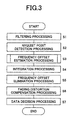
- Fig. 3 is a flowchart for explanation of the demodulation processing to be executed by the DSP 26.
- the DSP 26 applies filtering such as waveform shaping processing to the digital baseband signals supplied from the A/D converter circuits 25a and 25b (step S1). Thereby, the DSP 26 eliminates the high frequency components such as noise components higher than a predetermined cutoff frequency from the digital baseband signals.
- the DSP 26 executes the Nyquist point detection processing (step S2). Concretely, the DSP 26 detects the Nyquist point of the digital baseband signal to obtain digital baseband signal r(kN F +i) corresponding to the Nyquist point.
- the digital baseband signal r(kN F +i) corresponding to the Nyquist point is expressed as Formula (1) below.
- c(kN F +i) shows a distortion amount caused by fading.
- A shows the amplitudes of the signals
- b(kN F +i) shows symbol values.
- n(kN F +i) shows gauss noises.
- r(kN F + i) Ac(kN F + i)b(kN F + i) + n(kN F + i)
- the DSP 26 executes automatic frequency control processing (Step S3 through S5).
- the automatic frequency control processing frequency offset based on the oscillation frequency f o of the oscillation circuit 22 as a reference is estimated, and the estimated frequency offset is eliminated from the digital baseband signal r(kN F +i), whereby the frequency of the digital baseband signal r(kN F +i) is automatically controlled.
- the DSP 26 estimates the frequency of the direct wave and the center frequency of the Doppler spread based on the distortion amounts of the plurality of known signals periodically included in the digital baseband signal corresponding to the radio receiving signal, compensates the frequency offset of the digital baseband signal r(kN F +i) based on both the abovementioned frequency, and thereby automatically controls the frequencies of the digital baseband signal r(kN F +i).
- the DSP 26 estimates frequency offset of the digital baseband signal r(kN F +i) from the frequency of the direct wave and the center frequency of the Doppler spread that are estimated based on the distortion amounts of the plurality of known signals periodically included in the digital baseband signal r(kN F +i) corresponding to a radio receiving signal, eliminates the estimated frequency offset from the digital baseband signal r(kN F +i), whereby the frequency of the digital baseband signal r(kN F +i) is automatically controlled.
- the DSP 26 executes integration processing for integrating the determined phase difference ⁇ S (mLN F ) by one-symbol period T S (step S4).
- the DSP 26 cyclically sums phase differences ⁇ S (mLN F ) at each symbol period T S as shown in Formula (2) below.
- the DSP 26 obtains an accumulated phase difference ⁇ ((m-1)LN F +1N F +i).
- 1 indicates identification numbers corresponding one to one known signal blocks, and is a value of 0 or more and (L-1) or less (0 ⁇ 1 ⁇ L-1).
- L shows the number of known signal blocks included in the estimating period T.
- ⁇ ((m - 1)LN F + 1N F + i) ⁇ ((m - 1)LN F + 1N F + i - 1) + ⁇ S (mLN F )
- the DSP 26 executes frequency offset elimination processing for eliminating frequency offset from the digital baseband signal r(kN F +i) based on this accumulated phase difference ⁇ ((m-1)LN F +lN F +i) (step S5).
- the DSP 26 rotates in reverse the phase of the digital baseband signal r(kN F +i) by an amount in accordance with the accumulated phase difference ⁇ ((m-1)LN F +1N F +i).
- frequency offset can be eliminated from the digital baseband signal r(kN F +i). That is, as shown in Formula (3) below, the DSP 26 obtains a digital baseband signal r R (kN F +i) in which frequency offset has been eliminated.
- the DSP 26 automatically controls the frequency of the digital baseband signal.
- the DSP 26 executes fading distortion compensation processing for estimating and eliminating fading distortion from the digital baseband signal r R (kN F +i) (step S6).
- the DSP 26 extracts N P -symbol known signals from the digital baseband signal r R (kN F +i). The frequency offset caused by the transmitter 1 and receiver 10 has been already eliminated from these extracted known signals.
- the DSP 26 detects fading distortion based on the extracted N P -symbol known signals.
- the DSP 26 executes interpolation processing such as gauss interpolation, Wiener interpolation, based on the detected fading distortion.
- the DSP 26 thus estimates fading distortion in the information signal.
- the DSP 26 eliminates the estimated fading distortion. Thereby, the DSP 26 executes fading interpolation for the digital baseband signal r R (kN F +i).
- the DSP 26 executes data decision processing (step S7). Concretely, the DSP 26 dicides the original information signal based on the digital baseband signal in which fading has been compensated. Thus, the demodulation processing is completed.
- Fig. 5 is a flowchart for explanation of the frequency offset estimation processing.
- This frequency offset estimation processing includes the first frequency offset estimation processing and the second frequency offset estimation processing. That is, the DSP 26 estimates frequency offset by combining the first frequency offset estimation processing and the second frequency offset estimation processing.
- the frequency of the direct wave of the radio receiving signal is estimated as the first frequency offset.
- the center frequency of the Doppler spread of the radio receiving signal is estimated as the second frequency offset.
- the DSP 26 estimates the last frequency offset from the first and second frequency offsets estimated by these two frequency offset estimation processings.
- the reason why the two frequency offset estimation processings are combined is as follows.
- the frequency f D of the direct wave is regarded as frequency offset and compensated, as shown in Fig. 24B
- the Doppler spread apparently further broadens, and the BER characteristics deteriorate.
- the direct wave has frequency deviation corresponding to the Doppler shift amount f DP , however, the Doppler spread is left at the original degree of broadening. Therefore, in this case, the deterioration of the BER characteristics is less than that in the case where the frequency f D of the direct wave is regarded as frequency offset and compensated.
- Fig. 6 is a graph showing the BER characteristics.
- the center frequency f M is the optimum frequency offset. That is, in terms of prevention of deterioration in the BER characteristics, it can be said that the center frequency f M of the Doppler spread being regarded as the frequency offset is better than the frequency f D of the direct wave being regarded as the frequency offset.
- the frequency offset ⁇ f 1 2 ⁇ ⁇ ⁇ t
- the detecting range of the phase rotation amount ⁇ P is - ⁇ P ⁇ , and as a result, the estimating possible range of the frequency offset ⁇ f can be expressed by Formula (6) below.
- the frequency offset estimating range f DET1 in the first frequency offset estimation processing becomes a range between -R S /2 and R S /2.
- the frequency offset estimating range f DET2 becomes the same as the range expressed by the abovementioned Formula (6). That is, the frequency offset estimating range f DET2 in the second frequency offset estimation processing becomes the range between -R S /2N F and R S /2N F .
- the frequency offset estimating range f DET1 in the first frequency offset estimation processing is N F times larger than that in the second frequency offset estimation processing. That is, in the first frequency offset estimation processing, the frequency offset can be estimated in the relatively wide frequency offset estimating range f DET1 .
- both of the frequency f D of the direct wave and the center frequency f M of the Doppler spread are estimated, and both of these frequencies f D and f M are used for compensation for the frequency offset, whereby deterioration in the BER characteristics can be prevented while securing a sufficient frequency offset compensating range.
- the DSP 26 executes distortion amount detection processing first (step T1).
- the distortion amount detection processing the distortion amounts of the transmission channel are detected in symbol units based on the known signals. That is, as shown by Formula (7) below, based on the N P -symbol known signal blocks included in the digital baseband signal r(kN F +i), the DSP 26 detects the distortion amounts c EPi (N F +i) of the transmission channel for each symbol in the known signal blocks. In this case, the distortion amounts c EPi (kN F +i) of the transmission channel corresponding to the amplitude and the distortion amount of the phase of the digital baseband signal r(kN F +i).
- b P shows the symbol value of the known signal.
- the DSP 26 executes the first frequency offset estimation processing based on the detected distortion amounts c EPi (kN F +i) of the transmission channel (step T2).
- the DSP 26 estimates the frequency of the direct wave as the first frequency offset based on the distortion amounts c EPi (kN F +i) of the transmission channel.
- the DSP 26 estimates the phase difference ⁇ EP1 (mLN F ) corresponding to the phase rotation amount between the adjacent known signals as the first frequency offset based on the distortion amount c EPi (kN F +i) between the adjacent known signals among distortion amounts c EPi (kN F +i) of the transmission channel.
- the DSP 26 executes frequency offset elimination processing for eliminating the first frequency offset from the distortion amount of each known signal based on the estimated phase difference ⁇ EP1 (mLN F ) (step T3). More concretely, the DSP 26 compensates the phase by rotating the phases of the distortion amounts c EPi (kN F +i) of the transmission channel by the phase difference ⁇ EP1 (mLN F ) as shown by Formula (8). Thereby, the DSP 26 obtains the distortion amounts c EP1 (kN F +i) in which the first frequency offset has been eliminated.
- the DSP 26 executes the second frequency offset estimation processing (step T4).
- the DSP 26 estimates the second frequency offset based on the distortion amounts c EP1 (kN F +i) in which the first frequency offset has been eliminated. More concretely, the DSP 26 estimates the phase difference ⁇ EP2 (mLN F ) corresponding to the phase rotation amount for one symbol as the second frequency offset based on the distortion amount of the periodically inserted known signals among the distortion amounts c EP1 (kN F +i) in which the first frequency offset has been eliminated.
- the DSP 26 executes phase synthesis processing (step T5). Concretely, the DSP 26 synthesizes the two phase differences ⁇ EP1 (mLN F ) and ⁇ EP2 (mLN F ) as shown by Formula (9) to estimate the phase difference ⁇ S (mLN F ) as the last frequency offset.
- ⁇ S (mLN F ) ⁇ EP1 (mLN F ) + ⁇ EP2 (mLN F )
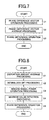
- Fig. 7 is a flowchart for detailed explanation of the first frequency offset estimation processing.
- the DSP 26 executes phase difference vector operation processing first (step U1). Concretely, the DSP 26 determines the phase difference vector D EP (kN F ) based on the distortion amounts C EPi (kN F +i) of the transmission channel. More concretely, as shown by Formula (10) below, based on the distortion amount between the adjacent known signals in an arbitrary known signal block among the distortion amounts C EPi (kN F +i) of the transmission channel, the DSP 26 determines the phase difference vector c EPi (kN F +i).
- i shows the identification numbers corresponding one to one known signals, and are zero or larger and (N P -2) or smaller (0 ⁇ i ⁇ N P -2).
- "*" shows a complex conjugate.
- step U2 the DSP 26 executes phase difference vector average processing (step U2). Concretely, the DSP 26 averages the phase difference vectors D EP (kN F ) in arbitrary known signal blocks for the estimation period T to determine the average phase difference vector D EPA (mLN F ).
- the DSP 26 collects the phase difference vectors D EP (kN F ) in known signal blocks for the estimation period T from the estimation time (m-1 )T to the estimation time mT (see Fig. 4). If the number of known signal blocks in the estimation period T is L, the DSP 26 obtains L of phase difference vectors D EP ((m-1)T+1N F ).
- 1 shows the identification numbers corresponding one to one known signal blocks, and is 0 or more and (L-1) or less (0 ⁇ 1 ⁇ L-1).
- the DSP 26 determines the average phase difference vector D EPA (mLN F ) by averaging the collected L of phase difference vectors D EP ((m-1)LN F +lN F ).
- the DSP 26 executes phase difference operation processing (step U3).
- the DSP 26 determines the phase difference ⁇ EP1 (mLN F ) based on the average phase difference vector D EPA (mLN F ).
- the first frequency offset according to the frequency of the direct wave is estimated within the frequency offset estimating range f DET1 that is wider than the frequency offset estimating range f DET2 .
- ⁇ EP1 (mLN F ) tan -1 Im[D EPA (mLN F )] Re[D EPA (mLN F )]
- Fig. 8 is a flowchart for explanation of the second frequency offset estimation processing.
- the DSP 26 executes distortion amount average processing first (step V1). Concretely, the DSP 26 applies average processing to the distortion amounts c EP1 (kN F +i) (0 ⁇ i ⁇ N P -1) of the transmission channel in the known signal blocks in which the first frequency offset has been eliminated to determine the average distortion amount c EP (kN F ).
- the DSP 26 sums the distortion amounts c EP1 (kN F +i) corresponding to each symbol in arbitrary known signal blocks, and divides the summed value by the symbol number N P of the known signals in the known signal blocks.
- the DSP 26 obtains the average distortion amount c EP (kN F ) of the transmission channel with regard to one known signal block in which noise or the like has been eliminated.
- the DSP 26 executes interblock discrete Fourier transform (DFT) processing based on this average distortion amount c EP (kN F ) (step v2).
- DFT interblock discrete Fourier transform
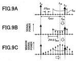
- the DSP 26 determines signal powers P f (n) corresponding to the plurality of frequency offset candidates n ⁇ f RES that are set for each predetermined estimation accuracy ⁇ f RES as shown by the circles in Fig. 9A within the frequency offset estimating range f DET2 .
- the frequency offset estimating range f DET2 is regulated by the known signal insertion period N F , and if the estimation accuracies ⁇ f RES are used, this range is a range between -M ⁇ f RES and M ⁇ f RES .
- M is a constant, and is approximately expressed by Formula (14) below.
- the DSP 26 rotates the phases of the average distortion amounts C EP ((m+1)N F ) in the frequency offset estimating range f DET2 by the phase amounts corresponding to the respective possible frequency offset candidates n ⁇ f RES . Thereafter, the DSP 26 vector-synthesizes the average distortion amounts c EP (m+1)N F ) whose phases have been rotated. Thereby, the DSP 26 obtains signal powers P f (n) corresponding to the plurality of frequency offset candidates n ⁇ f RES as shown by the group of arrows in Fig. 9B.
- R S shows the signal transmission rate
- n is a value between -(M+W) and (M+W).
- W is a parameter showing the frequency bandwidth of the frequency window described later.
- the DSP 26 executes window signal power operation processing (step V3).
- the DSP 26 determines the window signal powers E f (n) that correspond one to one frequency windows having predetermined frequency widths.
- the frequency width of a frequency window is 2W times of the estimation accuracy ⁇ f RES .
- W is set in accordance with the fading condition of the transmission channel, and is set to be, for example, two times of the Doppler spread.
- the DSP 26 sums the signal powers P f (n) of the frequency offset candidates n ⁇ f RES existing in this frequency window to determine the window signal power E f (n) corresponding to this frequency window.
- n is a value between -M and M.
- the window signal power E f (n) of the frequency offset candidate n ⁇ f RES becomes maximum.
- the DSP 26 executes maximum value detection processing (step V4). Concretely, as shown by Formula (17) below, the DSP 26 detects the maximum value among all window signal powers E f (n), and estimates the frequency offset candidate n ⁇ f RES corresponding to the maximum value as the second frequency offset. That is, the DSP 26 estimates the center frequency of the Doppler spread as the second frequency offset.
- Formula (17) the DSP 26 detects the maximum value among all window signal powers E f (n), and estimates the frequency offset candidate n ⁇ f RES corresponding to the maximum value as the second frequency offset. That is, the DSP 26 estimates the center frequency of the Doppler spread as the second frequency offset.
- the DSP 26 executes phase difference operation processing (step V5). Concretely, as shown by Formula (18) below, the DSP 26 determines the phase difference ⁇ EP2 (mLN F ) of one symbol based on the estimated second frequency offset. Thus, the phase difference ⁇ EP2 (mLN F ) corresponding to the center frequency of the Doppler spread is obtained.
- ⁇ EP2 (mLN F ) f OFST ⁇ 2 ⁇ R s
- the last frequency offset is estimated. Therefore, a sufficient frequency offset compensating range can be secured, and excellent BER characteristics can be realized. That is, securing of a sufficient frequency offset compensating range and realization of excellent BER characteristics are compatible with each other. Therefore, even under a Rician fading environment, compensation for fading distortion can be satisfactorily carried out. Therefore, the original data can be restored with high quality. Accordingly, service for receiver users can be improved.
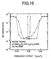
- Fig. 10 is a graph showing the frequency offset estimated characteristics relating to this Embodiment 1.
- the circles show the BER in the case where the value obtained by synthesizing the frequency of the direct wave and the center frequency of the Doppler spread is regarded as frequency offset as in Embodiment 1.
- the triangles show the BER when only the frequency of the direct wave is regarded as frequency offset.
- the squares show the BER when only the center frequency of the Doppler spread is regarded as frequency offset.
- Embodiment 1 As clearly understood from this graph, the BER characteristics relating to Embodiment 1 are more excellent than those in the case where only the frequency of the direct wave is regarded as frequency offset, and a frequency offset compensating range, which is wider than that in the case where only the center frequency of the Doppler spread is regarded as frequency offset, is realized in Embodiment 1.
- frequency offset candidates n ⁇ f RES are set for each estimation accuracy ⁇ f RES , signal powers P f (n) corresponding to the respective frequency offset candidates n ⁇ f RES are determined, and the signal powers P f (n) are smoothed by using the frequency windows, whereby the second frequency offset is estimated. Therefore, for example, if the estimation accuracies ⁇ f RES are finely divided, the estimation accuracy for the second frequency offset can be improved. Accordingly, further excellent BER characteristics can be realized.
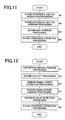
- Fig. 11 is a flowchart for explanation of the first frequency offset estimation processing relating to Embodiment 2 of the invention.
- the phase difference ⁇ EP1 (mLN F ) is determined as the first frequency offset from the average phase difference vector D EPA (mLN F ).
- the phase difference ⁇ EP1 (mLN F ) is determined as the first frequency offset by further averaging the average phase difference vectors D EPA (mLN F ) between the receiving burst signals by using a forgetting factor ⁇ . Thereby, the estimation accuracy for the frequency offset is improved.
- the DSP 26 determines the phase difference vectors D EP (mLN F ) (step W1), averages the phase difference vectors D EP (mLN F ) to determine the average phase difference vector D EPA (mLN F ) (step W2), and then executes interburst average processing (step W3).
- the average phase difference vectors D EPA (mLN F ) are further averaged between the receiving burst signals.
- the DSP 26 holds the average phase difference vector D EPA (mLN F ) at least until the next receiving burst signal is received. Based on the average phase difference vector D EPA (mLN F ) when the receiving burst signal B is received and the average phase difference vector ⁇ D EPA (mLN F )> B-1 when the one previous receiving burst signal (B-1) is received, the DSP 26 determines the average phase difference vector ⁇ D EPA (mLN F )> B by way of Formula (19) below.
- ⁇ is a forgetting factor, and is a value of 0 or more and 1 or less (0 ⁇ 1).
- ⁇ D EPA (mLN F ) ⁇ B D EPA (mLN F ) + ⁇ D EPA (mLN F ) ⁇ B-1
- the DSP 26 executes phase difference operation processing based on the average phase difference vector ⁇ D EPA (mLN F )> B (step W4).
- the DSP 26 determines the phase difference ⁇ EP1 (mLN F ) based on the average phase difference vector ⁇ D EPA (mLN F )> B .
- the DSP 26 estimates the first frequency offset coressponding to the frequency of the direct wave.
- ⁇ EP1 (mLN F ) tan -1 Im[ ⁇ D EPA (mLN F ) ⁇ ] Re[ ⁇ D EPA (mLN F ) ⁇ ]
- average processing is executed while the previous average phase difference vectors D EPA (mLN F ) are gradually forgotten by using the forgetting factor ⁇ . Therefore, even in the case where the fading condition changes with the times, average processing can be executed for the average phase difference vectors D EPA (mLN F ) while following the time variation. Accordingly, a phase difference vector in conformity with the condition of the transmission path can be obtained. Therefore, even under an environment where the C/N is low and the frequency offset changes with the times, the frequency offset can be estimated with high accuracy.
- Fig. 12 is a flowchart for explanation of the second frequency offset estimation processing relating to Embodiment 3 of the invention.
- the maximum value E f (n MAX ) of the signal power is detected among the window signal powers E f (n) determined by one window signal power operation processing, whereby the second frequency offset is estimated.
- the maximum value is detected to estimate the second frequency offset.
- the DSP 26 determines the average distortion amounts C EP (kN F ) (step X1), and applies interblock DFT processing to the average distortion amounts C EP (kN F ), and thereby determines the signal powers P f (n) (step x2), and furthermore, determines the window signal powers E f (n) from the signal powers P f (n)(step X3), and then executes window signal power average processing (step X4).
- the DSP 26 detects the maximum value ⁇ E f (n max )> B average window signal power among the determined average window signal powers ⁇ E f (n)> B (step X5).
- the DSP 26 estimates the phase difference ⁇ EP2 (mLN F ) corresponding to the possible frequency offset n ⁇ f RES corresponding to this maximum value ⁇ E f (n MAX )> B as the second frequency offset (step X6).
- Fig. 13 is a flowchart for explanation of the second frequency offset estimation processing relating to Embodiment 4 of the invention.
- Embodiment 3 influences of noise are eliminated by averaging the window signal powers E f (n), whereby the estimation accuracy of the second frequency offset is improved.
- improvement in the estimation accuracy of the second frequency offset by eliminating influences of noise can also be achieved by averaging the signal powers P f (n). Therefore, in this Embodiment 4, the signal powers P f (n) are averaged between the receiving burst signals to eliminate influences of noise, whereby the estimation accuracy of the second frequency offset is improved.
- the DSP 26 determines the window signal powers E f (n) based on average signal powers ⁇ P f (n)> B thus determined (step Y4), and then detects the maximum value E f (n max ) window signal power (step Y5), and estimates the phase difference ⁇ EP2 (mLN F ) corresponding to the frequency offset candidate n ⁇ f RES corresponding to the maximum value E f (n max ) as the second frequency offset (step Y6).
- the average processing is executed while the previous signal powers P f (n) are gradually forgotten by using the forgetting factor ⁇ . Therefore, even in the case where the fading condition changes with the times, the average processing of the signal powers can be executed while following the time variation. Accordingly signal powers in conformity with the conditions of the transmission channel can be obtained. Therefore, even under an environment where C/N is low and the frequency offset changes with the times, the frequency offset can be estimated with high accuracy.
- Fig. 14 is a flowchart for explanation of the first frequency offset estimation processing relating to Embodiment 5 of the invention.
- the phase difference vector D EP (kN F ) between the adjacent known signals is determined.
- this Embodiment 5 by determining only phase difference information that is the scalar quantity between the adjacent known signals based on the distortion amounts c EPi (kN F +i) of the transmission channel, the processing is simplified.
- the DSP 26 executes phase difference information operation processing first between the known signals (step Z1).
- phase difference information as the scalar quantity between adjacent known signals is determined. That is, as shown by Formula (24) below, the DSP 26 converts the distortion amounts c EP1 (kN F +i) of the transmission channel into phase information ⁇ EPi (kN F +i), and determines phase difference information ⁇ EP (kN F ) between adjacent known signals.
- i shows the identification numbers which correspond one to one known signals, and is a value between 0 and (N P -2) (0 ⁇ i ⁇ N P -2).
- the DSP 26 executes average processing for averaging the phase difference information ⁇ EP (kN F ) in one burst (step Z2). Concretely, the DSP 26 collects phase difference information ⁇ EP (kN F ) for the estimation period T from the estimation time (m-1)T to the estimation time mT. If the number of known signal blocks in the estimation period T is L, the DSP 26 obtains L of phase difference information ⁇ EP ((m-1)LN F +lN F ).
- 1 shows the indication numbers which correspond one to one known signal blocks, and is a value between 0 and (L-1) (0 ⁇ 1 ⁇ L-1).
- the DSP 26 applies average processing to the collected L of phase difference information ⁇ EP ((m-1)LN F +lN F ), whereby the average phase difference ⁇ EP1 (mLN F ) is determined as the first frequency offset.
- the average processing is executed by using only the phase difference information. Therefore, the processing can be simplified.
- Fig. 15 is a flowchart for explanation of the first frequency offset estimation processing relating to Embodiment 6 of the invention.
- the distortion amounts c EPi (kN F +i) of the transmission channel are multiplied by the complex conjugate and summed, whereby the phase difference vector D EP (kN F ) between adjacent known signals is determined.
- the phase difference vector D EP (kN F ) is determined.
- the DSP 26 executes inter-symbol DFT processing (step R1). More concretely, by applying the DFT processing to the distortion amounts c EPi (kN F +i) of the transmission channel, the DSP 26 determines signal electric powers P f1 (n) corresponding to the plurality of frequency offset candidates n ⁇ f RES .
- the DSP 26 rotates the phases of the distortion amounts c EPi ((m-1)LN F +lN F +i) of the transmission channel by the phase amounts corresponding to the respective frequency offset candidates n ⁇ f RES . Thereafter, the DSP 26 vector-synthesizes the distortion amounts c EPi ((m-1)LN F +lN F +i) whose phases have been rotated, and determines signal powers P f1 (n) corresponding to the plurality of frequency offset candidates n ⁇ f RES within the frequency offset estimating range.
- n is approximately a value between -R S /(2 ⁇ f RES ) and R S /(2 ⁇ f RES ).
- the DSP 26 vector-synthesizes the distortion amounts c EPi (m-1)LN F +lN F +i) whose phases have been rotated, and obtains signal powers P f1 (n) corresponding to the respective plurality of frequency offset candidates n ⁇ f RES .
- the DSP 26 executes window signal power operation processing (step R2). Concretely, as shown by Formula (27), the DSP 26 sums the signal powers P f1 (n) corresponding to the frequency offset candidates n ⁇ f RES in the window having a frequency width of 2W 1 ⁇ f RES , whereby the window signal powers E f1 (n) are determined.
- the DSP 26 executes maximum value detection processing to detect the maximum value E f1 (n MAX ) among the window signal powers E f1 (n) (step R3), and executes phase difference operation processing based on the detected maximum value E f1 (n MAX ) (step R4), whereby the phase difference ⁇ EP1 (mLN F ) is estimated as the first frequency offset.
- frequency offset candidates n ⁇ f RES are set for each estimation accuracy ⁇ f RES , signal powers P f1 (n) corresponding to the respective frequency offset candidates n ⁇ f RES are determined, and the signal powers P f1 (n) are smoothed by using the frequency window, whereby the first frequency offset is estimated. Therefore, for example, if the estimation accuracies ⁇ f RES are finely set, the estimation accuracy of the first frequency offset can be improved.
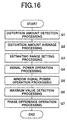
- Fig. 16 is a flowchart for explanation of the frequency offset estimation processing relating to Embodiment 7 of the invention.
- the distortion amounts c EPi (kN F +i) of the transmission channel are compensated based on the phase difference ⁇ EP1 (mLN F ) as the first frequency offset, and the phase difference ⁇ EP2 (mLN F ) as the second frequency offset based on the distortion amounts c EPi (kN F +i) after being compensated is estimated.
- the first frequency offset corresponds to the frequency f D of the direct wave
- the frequency f D of the direct wave exists near the center frequency f M of the Doppler spread (see Fig. 9A). Therefore, on supposition that a certain range around the frequency f D of the direct wave is a frequency offset estimating range, it can be expected that the center frequency f M of the Doppler spread exists within the range.
- the frequency offset estimating range for estimation of the second frequency offset based on the first frequency offset is regulated.
- the DSP 26 detects the distortion amounts c EPi (kN F +i) of the transmission channel (step Q1), and then executes the first frequency offset estimation processing and the second frequency offset estimation processing simultaneously. More concretely, the DSP 26 estimates the first frequency offset based on the abovementioned distortion amounts C EPi (kN F +i) of the transmission channel. The DSP 26 temporarily holds, for example, this first frequency offset.
- the DSP 26 executes the first frequency offset estimation processing and distortion amount average processing simultaneously (step Q2). Concretely, the DSP 26 applies average processing to the distortion amounts c EPi (kN F +i) of the transmission channel to determine the average distortion amount c EP (kN F ).
- the DSP 26 sets a frequency offset estimating range based on the first frequency offset (step Q3), and determines signal powers P f (n) corresponding to the plurality of possible frequency offsets n ⁇ f RES within the frequency offset estimating range respectively (step Q4).
- the DSP 26 accords the first frequency offset to any one of the frequency offset candidates n ⁇ f RES set in advance for each estimation accuracy ⁇ f RES .
- the frequency offset candidate in accordance with the first frequency offset is shown by N ⁇ f RES .
- the DSP 26 sets the range around this frequency offset candidate N ⁇ f RES , that is, the range between (-M+N) ⁇ f RES and (M+N) ⁇ f RES as the frequency offset estimation range.
- M is the constant shown in Formula (14).
- n is a value between (-M-W+N) and (M+W+N).
- the DSP 26 vector-synthesizes the average distortion amounts c EP ((m+1)N F ) whose phases have been rotated. Thereby, the DSP 26 determines signal powers P f (n) corresponding to the plurality of frequency offset candidates n ⁇ f RES respectively.
- the DSP 26 determines window signal power E f (n) by cyclically summing the signal powers P f (n) in a frequency window with a predetermined frequency width (step Q5).
- the DSP 26 determines the maximum value E f (n MAX ) of the window signal power (step Q6), and estimates the frequency offset candidate n ⁇ f RES of this maximum value E f (n MAX ) as the last frequency offset (step Q7).
- the frequency offset estimating range to estimate the frequency offset based on the first frequency offset is set. Therefore, the first frequency offset elimination processing and phase synthesis processing become unnecessary. Therefore, the processing can be simplified.
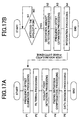
- Fig. 17 is a flowchart for explanation of demodulation processing relating to Embodiment 8 of the invention.
- Embodiment 1 the frequency offset elimination processing in which the phase of the digital baseband signal is rotated is executed after filtering processing.
- the frequency offset elimination processing is executed previous to the filtering processing.
- Frequency offset of the receiving burst signal occurs due to the stability of the oscillation circuit of the transmitter 1 and receiver 10 as explained in the subsection "Discription of the Related Art" above. Particularly, in the case where low-cost oscillation circuits are used, since the frequency stability is low, great frequency offset occurs. In addition, the frequency stability of the oscillation circuits is influenced by the surrounding environment such as temperature and changes in the power supply voltage.
- the frequency offset becomes greater in accordance with time elapse although the offset is slight at the beginning.
- the frequency bandwidth of the receiving burst signal may expand to a large frequency bandwidth in comparison with the cutoff frequency in the filtering processing. Therefore, a part of the receiving burst signal may be cut by the filtering processing. Accordingly, the data decision may not be sufficiently carried out.
- the frequency offset elimination processing is executed prior to the filtering processing.
- the frequency offset elimination processing is executed prior to the filtering processing, and distortion amount detection processing, frequency offset estimation processing, and integration processing are executed simultaneously with sequential processing including fading distortion compensation processing and data decision processing.
- step P1 when digital baseband signals are supplied from the A/D converter circuits 25a and 25b, previous to the filtering processing, the DSP 26 executes frequency offset elimination processing (step P1). Still more concretely, based on the accumulated phase difference ⁇ ((m-1)LN F +1N F +i) determined by the separately executed integration processing, the phases of the digital baseband signals are rotated in reverse. Thereby, digital baseband signals from which frequency offset has been eliminated are obtained.
- the DSP 26 applies filtering processing to the digital baseband signals (step P2) to eliminate noise components and the like. Thereafter, the DSP 26 detects a digital baseband signal corresponding to the Nyquist point (step S3), eliminates fading distortion from the digital baseband signal (step P4), and then executes data decision processing (step P5).
- the DSP 26 decides whether or not the digital baseband signal corresponding to the Nyquist point has been detected (step N1). If the Nyquist point has been detected, based on the digital baseband signal corresponding to the Nyquist point, the DSP 26 detects the distortion amount c EPi (kN F +i) of the transmission channel (step N2).
- the DSP 26 estimates the phase difference ⁇ S (mLN F ) corresponding to the frequency offset (step N3), and cyclically sums the phase differences ⁇ S (mLN F ), whereby an accumulated phase difference ⁇ ((m-1)LN F +lN F +i) is determined (step N4).
- the DSP 26 uses this determined accumulated phase difference ⁇ ((m-1)LN F +lN F +i) for the frequency offset elimination processing in step P1.
- the frequency offset elimination processing is executed before the filtering processing. Therefore, even if the frequency bandwidths of the receiving burst signals are greater than the cutoff frequency in the filtering processing, the frequency offset can be eliminated while a part of the receiving burst signals is not cut. Therefore, data decision can be satisfactorily carried out.
- Fig. 18 is a flowchart for explanation of demodulation processing relating to Embodiment 9 of the invention.
- Embodiments 1 through 8 by directly rotating the phase of the digital baseband signal, the frequency offset is compensated.
- the phase of the receiving burst signal is rotated by changing the frequency of the local oscillation signal generated at the oscillation circuit 22, whereby the frequency offset is compensated.
- digital signal processing by way of software is not applied to the digital baseband signal, but a voltage to be applied to the oscillation circuit 22 comprised of VCO is controlled to eliminate the frequency offset.
- step M1 filtering processing
- step M2 Nyquist point detection processing
- step M3 fading distortion compensation processing
- step M4 data decision processing
- the DSP 26 decides whether or not the digital baseband signal corresponding to the Nyquist point has been detected (step L1). In the case where the Nyquist point has been detected, the DSP 26 detects the distortion amount c EPi (kN F +i) of the transmission channel based on the digital baseband signal corresponding to the Nyquist point (step L2). Thereafter, the DSP 26 estimates frequency offset based on the distortion amount c EPi (kN F +i) of the transmission channel (step L3). Then, the DSP 26 supplies a voltage in accordance with the estimated frequency offset to the VCO 22 (step L4).
- the VCO 22 oscillates a local oscillation signal having an oscillation frequency which has deviated by an amount according to the frequency offset from the original oscillation frequency. Therefore, the frequency converter circuit 21 outputs an analog baseband signal from which frequency offset has been eliminated. Thus, excellent frequency offset compensation can be realized.
- Embodiment 9 by adjusting the frequency of the local oscillation signal generated by the VCO 22, the frequency offset is eliminated from the receiving IF signal. That is, before the filtering processing by the DSP 26, the frequency offset is eliminated. Therefore, as in the abovementioned Embodiment 8, even if the frequency bandwidth of the receiving burst signal expands to be larger than the cutoff frequency in the filtering processing, frequency offset can be eliminated while a part of the receiving burst signal is not cut. Therefore, the data decision can be satisfactorily carried out.
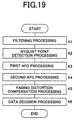
- Fig. 19 is a flowchart for explanation of demodulation processing relating to Embodiment 10 of the invention.
- the first frequency offset and the second frequency offset are synthesized to estimate the last frequency offset, and in accordance with this frequency offset, compensation for the frequency offset is carried out, whereby the frequency of the digital baseband signal is automatically controlled.
- frequency offset compensation in accordance with the first frequency offset is carried out for the digital baseband signals
- frequency offset compensation in accordance with the second frequency offset is carried out for digital baseband signals after the abovementioned compensation is carried out, whereby the frequency of the digital baseband signal is automatically controlled.
- the DSP 26 applies predetermined filtering processing to the digital baseband signals (step K1), and then detects a digital baseband signal corresponding to Nyquist point (step K2).
- the DSP 26 executes the first automatic frequency control processing (hereinafter, referred to as the first AFC processing) for the digital baseband signal (step K3), and then executes the second automatic frequency control processing (hereinafter, referred to as the second AFC processing) for the digital baseband signal after being subjected to the first AFC processing (step K4).
- the DSP 26 executes fading distortion compensation processing for the digital baseband signal after being subjected to the second AFC processing (step K5), and applies data decision processing to the signal (step K6), whereby data corresponding to the original information signal is restored.
- Fig. 20 is a flowchart for explanation of the first AFC processing.
- the DSP 26 detects the distortion amounts c EPi (kN F +i) of the transmission channel for each symbol (step J1), and then executes the first frequency offset estimation processing (step J2).
- the first frequency offset estimation processing is the same as that in the abovementioned Embodiment 1, and by this processing, the DSP 26 estimates the phase difference ⁇ EP1 (mLN F ) as the first frequency offset corresponding to the phase rotation amount for one symbol.
- the DSP 26 executes integration processing for cyclically summing the phase differences ⁇ EP1 (mLN F ) (step J3) to obtain an accumulated phase difference ⁇ 1 ((m-1)LN F +lN F +i).
- the DSP 26 obtains the phase difference ⁇ 1 ((m-1)LN F +lN F +i) accumulated from the estimation time mT for each symbol period T S .
- the DSP 26 executes the first frequency offset elimination processing (step J4). Concretely, based on the accumulated phase difference ⁇ 1 ((m-1)LN F +lN F +i), the DSP 26 rotates in reverse the phase of the digital baseband signal r(kN F +i) by an amount in accordance with the accumulated phase difference ⁇ 1 ((m-1)LN F +lN F +i). Thereby, the first frequency offset can be eliminated from the digital baseband signal r(kN F +i). Thus, the DSP 26 achieves automatic frequency control of the digital baseband signals r(kN F +i) based on the first frequency offset.
- Fig. 21 is a flowchart for explanation of the second AFC processing.
- the DSP 26 Based on the known signal blocks of the digital baseband signal after being subjected to the first AFC processing, the DSP 26 detects the distortion amount c EPi2 (kN F +i) of the transmission channel for each symbol in the known signal blocks (step I1).
- the DSP 26 executes the second frequency offset estimation processing that is the same as in Embodiment 1 (step I2). Thereby, the DSP 26 estimates the phase difference ⁇ EP2 (mLN F ) as the second frequency offset corresponding to the phase rotation amount for one symbol.
- the DSP 26 executes integration processing for cyclically summing the phase differences ⁇ EP2 (mLN F ) (step I3), and obtains an accumulated phase difference ⁇ 2 ((m-1)LN F +lN F +i). In this case, the DSP 26 obtains the phase difference ⁇ 2 ((m-1)LN F +1N F +i) accumulated from the estimation time mT for each symbol period T S .
- the DSP 26 executes the second frequency offset elimination processing (step I4). Concretely, based on the accumulated phase difference ⁇ 2 ((m-1)LN F +lN F +i), the DSP 26 rotates in reverse the phase of the digital baseband signal r R1 (kN F +i) by an amount according to the accumulated phase difference ⁇ 2 ((m-1)LN F +lN F +i). Thereby, the second frequency offset can be eliminated from the digital baseband signal r R1 (kN F +i). Thus, the DSP 26 achieves automatic frequency control of the digital baseband signal r R1 (kN F +i) based on the second frequency offset.
- Fig. 22 is a flowchart for explanation of demodulation processing relating to Embodiment 11 of the invention.
- the frequency offset elimination processing is executed after the filtering processing.
- the frequency offset elimination processing is executed before the filtering processing.
- the first frequency offset elimination processing that is a part of the first AFC processing is executed before the filtering processing, and the remaining processing of the first AFC processing, that is, distortion amount detection processing, the first frequency offset estimation processing, and integration processing are executed simultaneously with sequential processing.
- the DSP 26 executes the first frequency offset elimination processing (step H1). Still more concretely, the DSP 26 rotates in reverse the phases of the digital baseband signals by amounts according to the accumulated phase difference ⁇ ((m-1)LN F +lN F +i) corresponding to the first frequency offset determined by the integration processing executed simultaneously with the sequential processing. Thereby, digital baseband signals from which first frequency offset has been eliminated are obtained.
- the DSP 26 applies filtering processing to the digital baseband signals (step H2) to eliminate noise components and the like, and then detects a digital baseband signal corresponding to the Nyquist point (step H3). Thereafter, the DSP 26 executes the second AFC processing based on the digital baseband signal (step H4). By executing this second AFC processing, the DSP 26 can obtain a digital baseband signal in which the last frequency offset has been eliminated. Next, the DSP 26 eliminates fading distortion from the digital baseband signal (step H5), and then executes data decision processing (step H6).
- the DSP 26 decides whether or not the digital baseband signal corresponding to the Nyquist point has been detected (step G1). In the case where the Nyquist point has been detected, based on the digital baseband signal corresponding to the Nyquist point, the DSP 26 detects the distortion amount c EPi (kN F +i) of the transmission path (step G2).
- the DSP 26 estimates the phase difference ⁇ S (mLN F ) corresponding to the first frequency offset (step G3), and cyclically sums the phase differences ⁇ S (mLN F ), whereby an accumulated phase difference ⁇ ((m-1)LN F +lN F +i) is determined (step G4).
- the DSP 26 uses this determined accumulated phase difference ⁇ ((m-1)LN F +lN F +i) for the first frequency offset elimination processing in step H1.
- the first frequency offset elimination processing is executed before the filtering processing. Therefore, even when the frequency bandwidth of the receiving IF signal becomes larger than the cutoff frequency in the filtering processing, the first frequency offset can be eliminated while a part of the receiving IF signals is not cut. Therefore, data decision can be satisfactorily carried out.
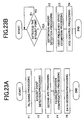
- Fig. 23 is a flowchart for explanation of demodulation processing relating to Embodiment 12 of the invention.
- Embodiment 10 by directly rotating the phase of the digital baseband signal, the frequency offset is compensated.
- this Embodiment 12 by adjusting the frequency of the local oscillation signal generated by the oscillation circuit 22 that is the VCO, the phase of the receiving burst signal is rotated, whereby the frequency offset is compensated.
- digital signal processing by way of software is not applied to the digital baseband signal, but the voltage to be applied to the oscillation circuit 22 formed of the VCO is controlled, whereby the frequency offset is eliminated.
- step F1 the filtering processing (step F1), Nyquist point detection processing (step F2), the second AFC processing (step F3), fading distortion compensation processing (step F4), and data decision processing (step F5) are executed, and simultaneously with these sequential processings, as shown in Fig. 23B, distortion amount detection processing, the first frequency offset estimation processing, and VCO control processing for controlling the voltage to be applied to the VCO 22 are executed.
- the DSP 26 decides whether or not the digital baseband signal corresponding to the Nyquist point has been detected (step E1). In the case where the Nyquist point has been detected, based on the digital baseband signal corresponding to the Nyquist point, the DSP 26 detects the distortion amount c EPi (kN F +i) of the transmission channel (step E2). Thereafter, the DSP 26 estimates the first frequency offset based on the distortion amount c EPi (kN F +i) of the transmission channel (step E3). Then, the DSP 26 applies a voltage according to the estimated first frequency offset to the VCO 22 (step E4).
- the VCO 22 oscillates the local oscillation signal having an oscillation frequency deviated by an amount in accordance with the first frequency offset from the original oscillation frequency. Therefore, the frequency converter circuit 21 outputs analog baseband signals in which the first frequency offset has been eliminated. Thus, excellent frequency offset compensation can be realized.
- the Embodiments of the invention are as described above, however, the invention is not limited to the abovementioned Embodiments.
- the case where the TDMA is applied as the communications method is described.
- the FDMA Frequency Division Multiple Access
- CDMA Code Division Multiple Access
- the radio receiving signals are not burst signals but are continuous signals as in the case where TDMA is applied.
- the invention can be easily applied even to this case.
Landscapes
- Engineering & Computer Science (AREA)
- Computer Networks & Wireless Communication (AREA)
- Signal Processing (AREA)
- Cable Transmission Systems, Equalization Of Radio And Reduction Of Echo (AREA)
- Digital Transmission Methods That Use Modulated Carrier Waves (AREA)
- Circuits Of Receivers In General (AREA)
- Channel Selection Circuits, Automatic Tuning Circuits (AREA)
Abstract
The demodulator of the invention includes a DSP. The DSP
determines the distortion amount of the transmission channel
based on known signals included in a radio receiving signal,
and estimates the frequency of the direct wave based on the
distortion amount. Furthermore, the DSP rotates the phase of
the distortion amount based on the phase amount corresponding
to the estimated frequency of the direct wave. Next, the DSP
estimates the center frequency of the Doppler spread based on
the distortion amount after the phase is rotated. Furthermore,
the DSP synthesizes the phase amount corresponding to the
estimated center frequency of the Doppler spread and the phase
amount corresponding to the frequency of the direct wave to
estimate the last frequency offset. Thereafter, the DSP
eliminates frequency offset of the radio receiving signal based
on the estimated frequency offset. Thereby, a sufficient
frequency offset compensating range can be secured, and
excellent BER characteristics can be realized.
Description
The present invention relates to an automatic frequency
control method and device, which are applied to digital
demodulation processing in satellite communication, mobile
satellite communication, mobile terrestrial communication,
and a demodulator to which said device is applied.
Recently, in satellite communication, mobile satellite
communication, and mobile terrestrial communication, digital
modulation and demodulation have been actively researched. In
particular, in the environment of mobile communications, a
radio signal is greatly influenced by fading. Therefore,
various demodulation systems which stably operate even in such
a fading environment have been considered. Among these systems,
a system, which is constructed so that absolute coherent
detection can be executed even in a fading environment by
estimating and compensating fading distortion by using known
signals, has been recognized. In the case where fading
distortion is estimated and compensated after quasi-coherent
detection or the like is carried out by this system, to estimate
and compensate fading distortion with high accuracy, it is
necessary that the frequency offset between the carrier wave
frequency of a radio transmission signal and the oscillation
frequency of a reference signal for quasi-coherent detection
is small.
However, in the case where the frequency stability and
accuracy of the oscillation circuit of a transmitter-receiver
are insufficient, unless the frequency of a radio receiving
signal is automatically controlled by eliminating this
frequency offset by some processing, fading distortion cannot
be estimated and compensated with high accuracy.
In mobile communication, transmission and receiving are
carried out between a fixed station and a mobile station or
between mobile stations. Therefore, when two stations
relatively move, the frequency of a radio receiving signal
deviates due to Doppler variation. Therefore, even if the
stability and accuracy of the oscillation circuit of the
transmitter-receiver are good, frequency offset occurs between
the frequency of the radio receiving signal and the oscillation
frequency of the reference signal.
A technique for compensating frequency offset is
disclosed in, for example, Japanese Patent Laid-Open No.
93302/1997 titled "DIGITAL MOBILE RADIO COMMUNICATION METHOD" .
By the conventional technique disclosed in this document,
frequency offset is eliminated by using phase fluctuation
information of known signals (pilot signals).
In this conventional technique, a radio transmission
signal into which two-symbol known signals have been inserted
every inserting period NF from the transmission side is
transmitted. On the other hand, at the receiving side, the phase
change amount between the sequential two-symbol known signals
is calculated, and in accordance with the calculated phase
change amount, the phase of the radio receiving signal is
rotated. Frequency offset is thus eliminated from the radio
receiving signal.
In electric wave transmission channels, there is a Rician
fading transmission channel in which direct waves and
multi-path waves are mixed. In this case, the direct wave is
Doppler-shifted. Therefore, the frequency fD of the direct wave
further deviates by Doppler-shift amount fDP caused by the
Doppler-shifting from the offset fOFST caused by stability of
the oscillation circuit as shown in Fig. 24A.
On the other hand, in the abovementioned prior art, the
phase change amount between the sequential two-symbol known
signals is supposed as frequency offset. The frequency offset
calculated in this case is equivalent to the difference between
the oscillation frequency fo at the receiver side and the
frequency fD of the direct wave. That is, in the prior art, as
shown in Fig. 24B, frequency control is carried out so that the
frequency fD of the direct wave almost coincides with the
oscillation frequency fo. In this case, the center frequency
fM of the Doppler spread deviates from the oscillation frequency
fo by the Doppler-shift amount fDP. Therefore, the Doppler spread
apparently further broadens, so that the frequency
corresponding to the end of the Doppler spread greatly deviates
from the oscillation frequency fo. Accordingly, frequency
offset cannot be satisfactorily compensated. Therefore, bit
error rate characteristics (hereinafter, referred to as BER
characteristics) after the radio receiving signal is
demodulated may deteriorate.
The object of the invention is therefore to solve the
abovementioned technical problems and provide an automatic
frequency control method and device by which satisfactory BER
characteristics can be realized without being influenced by a
Doppler-shifted direct wave in a Rician fading environment
where the direct wave has Doppler-shifted.
Another object of the invention is to provide a
demodulator by which demodulation accuracy can be improved by
applying the abovementioned automatic frequency control device
to this demodulator.
In order to achieve the abovementioned objects, an
automatic frequency control method of the invention, which
controls the frequency of a radio receiving signal by
compensating frequency offset of the radio receiving signal
that periodically includes a plurality of adjacent known
signals, comprising, based on the distortion amount of each
known signal included in the radio receiving signal, the
frequency of the direct wave of the radio receiving signal and
the center frequency of the Doppler spread of the radio
receiving signal are estimated, and based on both of the
frequencies, frequency offset of the radio receiving signal is
compensated.
In this construction, by compensating the frequency
offset based on the frequency of the direct wave, the
compensating range of frequency offset can be sufficiently
secured, and by compensating the frequency offset based on the
center frequency of the Doppler spread, satisfactory BER
characteristics can be secured. That is, compatibility with
securing of a sufficient frequency offset compensating range
and securing of satisfactory BER characteristics can be
realized.
In addition, the abovementioned construction is applied
to a demodulator, whereby demodulation processing can be
executed for a radio receiving signal in which frequency offset
has been satisfactorily eliminated. Therefore, the
demodulation quality can be improved.
Hereinafter, Embodiments of the invention are explained
in detail with reference to the attached drawings.
Fig. 1 is a block diagram showing the construction of a
radio communication system to which an automatic frequency
control method relating to Embodiment 1 of the invention is
applied. This radio communication system comprises transmitter
1 and receiver 10, and has a function for estimating and
eliminating frequency offset of a burst signal radio-transmitted
from the transmitter 1 by receiver 10.
Concretely, for this radio communication system, a
satellite communication system, mobile satellite
communication system, and mobile terrestrial communication
system can be applied. In the satellite communication system,
transmitter 1 and receiver 10 are applied to earth stations set
at different positions on the earth. In the mobile satellite
communication system, the transmitter 1 is applied to either
an earth station or a mobile station that is set on the earth,
and the receiver 10 is applied to an opposite station of the
transmitter 1 of the two stations. In the mobile terrestrial
communication system, the transmitter 1 is applied to either
a base station or a mobile station, and the receiver 10 is applied
to an opposite station of the transmitter 1 of the two stations.
As a mobile station in the mobile satellite communication
system, a satellite mobile phone of a single mode or a dual mode
can be applied. In addition, a cellular phone can be applied
to the mobile station in the mobile terrestrial communication
system.
This communication system uses the TDMA (Time Division
Multiple Access) as a communication method. Therefore, the
transmitter 1 radio-transmits a burst signal synchronized with
a predetermined time slot to the receiver 10. The receiver 10
demodulates the receiving burst signal, eliminates frequency
offset, and then restores the original signal.
The transmitter 1 comprises known signal insertion
circuit 2, modulation circuit 3, and transmission circuit 4.
The known signal insertion circuit 2 periodically inserts known
signals into information signals to be transmitted, and
generates burst signals before modulation. Concretely, as shown
in Fig. 2A, the known signal insertion circuit 2 inserts
NP-symbol sequential known signal rows (hereinafter, referred
to as known signal blocks) into (NF-NP)-symbol information at
every NF-symbol periods. NP is an integer of 2 or more (NP≥2).
The timings at which the known signals are inserted are shown
by (kNF+i)TS. Herein, k indicates the insertion order of the
known signals. i is a value between zero and (NP-1) (0≤i≤NP-1).
TS is a symbol period.
The known signal insertion circuit 2 provides a burst
signal before being modulated to the modulation circuit 3. The
modulation circuit 3 modulates this non-modulated burst signal,
and outputs it as a burst signal after being modulated. The
modulation circuit 3 synchronizes the modulated burst signal
with a predetermined time slot and provides the signal to the
transmission circuit 4. Concretely, as shown in Fig. 2B the
modulation circuit 3 synchronizes burst signals B, B+1, B+2,
B+3... with predetermined time slots S1, S2, S3, S4... and
provides the signals to the transmission circuit 4. The
transmission circuit 4 superposes the burst signals on electric
waves and transmits them to the receiver 10.
The receiver 10 includes receiving circuit 11 and
demodulator 12. The receiving circuit 11 is comprised of an
amplifier, a frequency converter, and the like, and converts
the frequency of the receiving burst signal which is a radio
receiving signal into an intermediate frequency and outputs it
as a receiving IF signal. The demodulator 12 demodulates the
receiving IF signal outputted from the receiving circuit 11 by
quasi-coherent detection, and restores the original
information signal. More concretely, the demodulator 12
comprises frequency converter circuit 21, two A/D
(analog/digital) converter circuits 25a and 25b, and DSP
(Digital Signal Processor) 26 as an automatic frequency control
device or digital signal processing device, and restores the
original information signal by digitally executing
demodulation processing by the DSP 26.
The frequency converter circuit 21 converts a receiving
IF signal periodically including a plurality of known signals
into an analog baseband signal, and the circuit includes one
oscillation circuit 22, two multiplication circuits 23a and 23b,
and π/2 phase shift circuit 24. The oscillation circuit 22
generates local oscillation signals with a predetermined
oscillation frequency. The local oscillation signals generated
by the oscillation circuit 22 are inputted into two
multiplication circuits 23a and 23b. In this case, the local
oscillation signal is inputted into the multiplication circuit
23a for I channel via the π/2 phase shift circuit 24. The π/2
phase shift circuit 24 shifts the phases of the local
oscillation signals by π/2. Therefore, the local oscillation
signals whose phases are shifted by π/2 from each other are
inputted into the multiplication circuits 23a and 23b.
The multiplication circuits 23a and 23b each mix the
receiving IF signals and the local oscillation signals. As a
result, I channel and Q channel analog baseband signals are
generated. These generated analog baseband signals are supplied
to the A/ D converter circuits 25a and 25b respectively. The A/ D
converter circuits 25a and 25b each convert the analog baseband
signals into I channel and Q channel digital baseband signals.
The digital baseband signals are supplied to DSP 26
respectively.
The DSP 26 receives the inputs of the digital baseband
signals generated by the A/ D converter circuits 25a and 25b,
and based on the distortion amounts of the known signals
included in the inputted digital baseband signals, estimates
the frequency of the direct wave and the center frequency of
the Doppler spread, and compensates frequency offset based on
these estimated frequencies. Thus, the DSP 26 automatically
controls the frequencies of the digital baseband signals.
Furthermore, the DSP 26 eliminates fading distortion from the
digital baseband signals from which frequency offset has been
compensated, and then demodulates the digital baseband signals,
whereby the original information signals are restored.
More concretely, the DSP 26 has storage 26a comprised of
a ROM or the like. In the storage 26a, a demodulation processing
program which is a computer program is stored. By executing the
demodulation processing program stored in the storage 26a, the
DSP 26 executes serial demodulation processing including
estimation of the abovementioned two frequencies, compensation
for frequency offset, compensation for fading distortion and
demodulation.
Fig. 3 is a flowchart for explanation of the demodulation
processing to be executed by the DSP 26. The DSP 26 applies
filtering such as waveform shaping processing to the digital
baseband signals supplied from the A/ D converter circuits 25a
and 25b (step S1). Thereby, the DSP 26 eliminates the high
frequency components such as noise components higher than a
predetermined cutoff frequency from the digital baseband
signals.
Thereafter, the DSP 26 executes the Nyquist point
detection processing (step S2). Concretely, the DSP 26 detects
the Nyquist point of the digital baseband signal to obtain
digital baseband signal r(kNF+i) corresponding to the Nyquist
point. The digital baseband signal r(kNF+i) corresponding to
the Nyquist point is expressed as Formula (1) below. In Formula
(1) below, c(kNF+i) shows a distortion amount caused by fading.
In addition, A shows the amplitudes of the signals, and b(kNF+i)
shows symbol values. Furthermore, n(kNF+i) shows gauss noises.
r(kNF + i) = Ac(kNF + i)b(kNF + i) + n(kNF + i)
Thereafter, the DSP 26 executes automatic frequency
control processing (Step S3 through S5). In the automatic
frequency control processing, frequency offset based on the
oscillation frequency fo of the oscillation circuit 22 as a
reference is estimated, and the estimated frequency offset is
eliminated from the digital baseband signal r(kNF+i), whereby
the frequency of the digital baseband signal r(kNF+i) is
automatically controlled. In other words, the DSP 26 estimates
the frequency of the direct wave and the center frequency of
the Doppler spread based on the distortion amounts of the
plurality of known signals periodically included in the digital
baseband signal corresponding to the radio receiving signal,
compensates the frequency offset of the digital baseband signal
r(kNF+i) based on both the abovementioned frequency, and thereby
automatically controls the frequencies of the digital baseband
signal r(kNF+i).
Further in other words, the DSP 26 estimates frequency
offset of the digital baseband signal r(kNF+i) from the
frequency of the direct wave and the center frequency of the
Doppler spread that are estimated based on the distortion
amounts of the plurality of known signals periodically included
in the digital baseband signal r(kNF+i) corresponding to a radio
receiving signal, eliminates the estimated frequency offset
from the digital baseband signal r(kNF+i), whereby the frequency
of the digital baseband signal r(kNF+i) is automatically
controlled.
More concretely explaining the automatic frequency
control processing, the DSP 26 executes frequency offset
estimation processing first (step S3). More specifically, the
DSP 26 estimates a phase difference S(mLNF) corresponding to
the phase rotation amount of one symbol as frequency offset
based on the digital baseband signal r(kNF+i). Still more
specifically, the DSP 26 determines a phase difference S(mLNF)
as frequency offset at each estimating time mT (m: natural
number) that comes after each estimating period T (=LNFTS) (see
Fig. 4) based on the distortion amounts of the plurality of known
signals included in the digital baseband signal r(kNF+i).
Next, the DSP 26 executes integration processing for
integrating the determined phase difference S(mLNF) by one-symbol
period TS (step S4). Concretely, the DSP 26 cyclically
sums phase differences S(mLNF) at each symbol period TS as shown
in Formula (2) below. Thereby, the DSP 26 obtains an accumulated
phase difference ((m-1)LNF+1NF+i). In Formula (2) below, 1
indicates identification numbers corresponding one to one known
signal blocks, and is a value of 0 or more and (L-1) or less
(0≤1≤L-1). L shows the number of known signal blocks included
in the estimating period T.
((m - 1)LNF + 1NF + i) = ((m - 1)LNF + 1NF + i - 1) + S (mLNF )
Thereafter, the DSP 26 executes frequency offset
elimination processing for eliminating frequency offset from
the digital baseband signal r(kNF+i) based on this accumulated
phase difference ((m-1)LNF+lNF+i) (step S5). Concretely, the
DSP 26 rotates in reverse the phase of the digital baseband
signal r(kNF+i) by an amount in accordance with the accumulated
phase difference ((m-1)LNF+1NF+i). Thereby, frequency offset
can be eliminated from the digital baseband signal r(kNF+i).
That is, as shown in Formula (3) below, the DSP 26 obtains a
digital baseband signal rR(kNF+i) in which frequency offset has
been eliminated. Thus, the DSP 26 automatically controls the
frequency of the digital baseband signal.

Thereafter, the DSP 26 executes fading distortion
compensation processing for estimating and eliminating fading
distortion from the digital baseband signal rR(kNF+i) (step S6).
Concretely, the DSP 26 extracts NP-symbol known signals from
the digital baseband signal rR(kNF+i). The frequency offset
caused by the transmitter 1 and receiver 10 has been already
eliminated from these extracted known signals.
The DSP 26 detects fading distortion based on the
extracted NP-symbol known signals. The DSP 26 executes
interpolation processing such as gauss interpolation, Wiener
interpolation, based on the detected fading distortion. The DSP
26 thus estimates fading distortion in the information signal.
Furthermore, the DSP 26 eliminates the estimated fading
distortion. Thereby, the DSP 26 executes fading interpolation
for the digital baseband signal rR(kNF+i).
Thereafter, the DSP 26 executes data decision processing
(step S7). Concretely, the DSP 26 dicides the original
information signal based on the digital baseband signal in which
fading has been compensated. Thus, the demodulation processing
is completed.
Fig. 5 is a flowchart for explanation of the frequency
offset estimation processing. This frequency offset estimation
processing includes the first frequency offset estimation
processing and the second frequency offset estimation
processing. That is, the DSP 26 estimates frequency offset by
combining the first frequency offset estimation processing and
the second frequency offset estimation processing.
In the first frequency offset estimation processing, the
frequency of the direct wave of the radio receiving signal is
estimated as the first frequency offset. In the second frequency
offset estimation processing, the center frequency of the
Doppler spread of the radio receiving signal is estimated as
the second frequency offset. The DSP 26 estimates the last
frequency offset from the first and second frequency offsets
estimated by these two frequency offset estimation processings.
Thus, the reason why the two frequency offset estimation
processings are combined is as follows. As explained in the
subsection "Description of the Related Art", in the case where
the frequency fD of the direct wave is regarded as frequency
offset and compensated, as shown in Fig. 24B, the Doppler spread
apparently further broadens, and the BER characteristics
deteriorate. On the other hand, in the case where the center
frequency fM of the Doppler broadening is regarded as frequency
offset and compensated, as shown in Fig. 24C, the direct wave
has frequency deviation corresponding to the Doppler shift
amount fDP, however, the Doppler spread is left at the original
degree of broadening. Therefore, in this case, the
deterioration of the BER characteristics is less than that in
the case where the frequency fD of the direct wave is regarded
as frequency offset and compensated.
Fig. 6 is a graph showing the BER characteristics. As can
be clearly understood from this graph, at the point where the
compensation for a frequency close to the center frequency fM
of the Doppler spread suppresses the deterioration of the BER
characteristics more greatly than in the case where the
frequency fD of the direct wave is compensated, it is understood
that the center frequency fM is the optimum frequency offset.
That is, in terms of prevention of deterioration in the BER
characteristics, it can be said that the center frequency fM
of the Doppler spread being regarded as the frequency offset
is better than the frequency fD of the direct wave being regarded
as the frequency offset.
On the other hand, in the case where the center frequency
fM of the Doppler spread is regarded as frequency offset and
compensated, prevention of deterioration in the BER
characteristics is possible, however, there is a problem where
the frequency offset compensating range is relatively narrow.
On the other hand, in the case where the frequency fD of the
direct wave is regarded as frequency offset and compensated,
a relatively wide frequency offset compensating range can be
secured.
Concretely, on supposition that the phase rotates by Δ
in a certain time Δt, the frequency offset Δf can be expressed
by Formula (4) below.
Δf = 12π ΔΔt
When this frequency offset Δf is estimated by using the
phase rotation amount between the known signals, the offset can
be expressed by Formula (5) below. In Formula (5) below, ΔP
shows the phase rotation amount between the known signals. In
addition, RS(symbol/s) shows the transmission rate of the
signals.
Δf = 12π ΔΔt = 12π RS NF ΔP
The detecting range of the phase rotation amount ΔP is
-π≤ΔP≤π, and as a result, the estimating possible range of the
frequency offset Δf can be expressed by Formula (6) below.
-RS 2NF ≤ Δf ≤ RS 2NF
When the frequency fD of the direct wave is estimated,
since the phase rotation amount between the adjacent known
signals is used, the fD becomes equivalent to the value obtained
by Formula (6) upon substituting 1 for NF. That is, the frequency
offset estimating range fDET1 in the first frequency offset
estimation processing becomes a range between -RS/2 and RS/2.
In addition, when the center frequency fM of the Doppler
spread is estimated, since the phase rotation amount between
the known signal blocks inserted for each NF symbol is used,
the frequency offset estimating range fDET2 becomes the same as
the range expressed by the abovementioned Formula (6). That is,
the frequency offset estimating range fDET2 in the second
frequency offset estimation processing becomes the range
between -RS/2NF and RS/2NF.
Thus, it is understood that the frequency offset
estimating range fDET1 in the first frequency offset estimation
processing is NF times larger than that in the second frequency
offset estimation processing. That is, in the first frequency
offset estimation processing, the frequency offset can be
estimated in the relatively wide frequency offset estimating
range fDET1.
From the above description, in this Embodiment 1, both
of the frequency fD of the direct wave and the center frequency
fM of the Doppler spread are estimated, and both of these
frequencies fD and fM are used for compensation for the frequency
offset, whereby deterioration in the BER characteristics can
be prevented while securing a sufficient frequency offset
compensating range.
Hereinafter, the frequency offset estimation processing
is explained in detail. The DSP 26 executes distortion amount
detection processing first (step T1). In the distortion amount
detection processing, the distortion amounts of the
transmission channel are detected in symbol units based on the
known signals. That is, as shown by Formula (7) below, based
on the NP-symbol known signal blocks included in the digital
baseband signal r(kNF+i), the DSP 26 detects the distortion
amounts cEPi(NF+i) of the transmission channel for each symbol
in the known signal blocks. In this case, the distortion amounts
cEPi(kNF+i) of the transmission channel corresponding to the
amplitude and the distortion amount of the phase of the digital
baseband signal r(kNF+i). In addition, in Formula (7) below,
bP shows the symbol value of the known signal.

Thereafter, the DSP 26 executes the first frequency
offset estimation processing based on the detected distortion
amounts cEPi(kNF+i) of the transmission channel (step T2).
Concretely, the DSP 26 estimates the frequency of the direct
wave as the first frequency offset based on the distortion
amounts cEPi(kNF+i) of the transmission channel. More concretely,
the DSP 26 estimates the phase difference EP1(mLNF)
corresponding to the phase rotation amount between the adjacent
known signals as the first frequency offset based on the
distortion amount cEPi(kNF+i) between the adjacent known signals
among distortion amounts cEPi(kNF+i) of the transmission
channel.
Thereafter, the DSP 26 executes frequency offset
elimination processing for eliminating the first frequency
offset from the distortion amount of each known signal based
on the estimated phase difference EP1(mLNF) (step T3). More
concretely, the DSP 26 compensates the phase by rotating the
phases of the distortion amounts cEPi(kNF+i) of the transmission
channel by the phase difference EP1(mLNF) as shown by Formula
(8). Thereby, the DSP 26 obtains the distortion amounts
cEP1(kNF+i) in which the first frequency offset has been
eliminated.
cEP1 (kNF + i) = cEPi (kNF + i)exp[- j(kNF + i)]
(kNF + i) = (kNF + i - 1) + EP1 (mLNF )
Thereafter, the DSP 26 executes the second frequency
offset estimation processing (step T4). Concretely, the DSP 26
estimates the second frequency offset based on the distortion
amounts cEP1(kNF+i) in which the first frequency offset has been
eliminated. More concretely, the DSP 26 estimates the phase
difference EP2(mLNF) corresponding to the phase rotation amount
for one symbol as the second frequency offset based on the
distortion amount of the periodically inserted known signals
among the distortion amounts cEP1(kNF+i) in which the first
frequency offset has been eliminated.
Thereafter, the DSP 26 executes phase synthesis
processing (step T5). Concretely, the DSP 26 synthesizes the
two phase differences EP1(mLNF) and EP2(mLNF) as shown by Formula
(9) to estimate the phase difference S(mLNF) as the last
frequency offset.
S (mLNF ) = EP1 (mLNF ) + EP2 (mLNF )
Fig. 7 is a flowchart for detailed explanation of the
first frequency offset estimation processing. The DSP 26
executes phase difference vector operation processing first
(step U1). Concretely, the DSP 26 determines the phase
difference vector DEP(kNF) based on the distortion amounts
CEPi(kNF+i) of the transmission channel. More concretely, as
shown by Formula (10) below, based on the distortion amount
between the adjacent known signals in an arbitrary known signal
block among the distortion amounts CEPi(kNF+i) of the
transmission channel, the DSP 26 determines the phase
difference vector cEPi(kNF+i). In Formula (10) below, i shows
the identification numbers corresponding one to one known
signals, and are zero or larger and (NP-2) or smaller (0≤i≤NP-2).
In addition, "*" shows a complex conjugate.

Thereafter, the DSP 26 executes phase difference vector
average processing (step U2). Concretely, the DSP 26 averages
the phase difference vectors DEP(kNF) in arbitrary known signal
blocks for the estimation period T to determine the average
phase difference vector DEPA(mLNF).
More concretely, the DSP 26 collects the phase difference
vectors DEP(kNF) in known signal blocks for the estimation period
T from the estimation time (m-1 )T to the estimation time mT (see
Fig. 4). If the number of known signal blocks in the estimation
period T is L, the DSP 26 obtains L of phase difference vectors
DEP((m-1)T+1NF). Herein, 1 shows the identification numbers
corresponding one to one known signal blocks, and is 0 or more
and (L-1) or less (0≤1≤L-1). Thereafter, as shown by Formula
(11) below, the DSP 26 determines the average phase difference
vector DEPA(mLNF) by averaging the collected L of phase
difference vectors DEP((m-1)LNF+lNF).

Then, the DSP 26 executes phase difference operation
processing (step U3). Concretely, as shown by Formula (12) below,
the DSP 26 determines the phase difference EP1(mLNF) based on
the average phase difference vector DEPA(mLNF). Thus, the first
frequency offset according to the frequency of the direct wave
is estimated within the frequency offset estimating range fDET1
that is wider than the frequency offset estimating range fDET2.
EP1 (mLNF ) = tan-1 Im[DEPA (mLNF )]Re[DEPA (mLNF )]
Fig. 8 is a flowchart for explanation of the second
frequency offset estimation processing. The DSP 26 executes
distortion amount average processing first (step V1).
Concretely, the DSP 26 applies average processing to the
distortion amounts cEP1(kNF+i) (0≤i≤NP-1) of the transmission
channel in the known signal blocks in which the first frequency
offset has been eliminated to determine the average distortion
amount cEP(kNF).
More concretely, as shown by Formula (13) below, the DSP
26 sums the distortion amounts cEP1(kNF+i) corresponding to each
symbol in arbitrary known signal blocks, and divides the summed
value by the symbol number NP of the known signals in the known
signal blocks. Thus, the DSP 26 obtains the average distortion
amount cEP(kNF) of the transmission channel with regard to one
known signal block in which noise or the like has been
eliminated.

Next, the DSP 26 executes interblock discrete Fourier
transform (DFT) processing based on this average distortion
amount cEP(kNF) (step v2). Concretely, the DSP 26 applies DFT
processing to the average distortion amounts
cEP((m+1)NF)(0≤1≤L-1) in certain L of known signal blocks within
the estimation period T (=LNFTS), and thereby determines signal
electric powers Pf(n) corresponding to the plurality of
frequency offset candidates nΔfRES.
More concretely, the DSP 26 determines signal powers Pf(n)
corresponding to the plurality of frequency offset candidates
nΔfRES that are set for each predetermined estimation accuracy
ΔfRES as shown by the circles in Fig. 9A within the frequency
offset estimating range fDET2. Herein, the frequency offset
estimating range fDET2, as mentioned above, is regulated by the
known signal insertion period NF, and if the estimation
accuracies ΔfRES are used, this range is a range between -MΔfRES
and MΔfRES. M is a constant, and is approximately expressed by
Formula (14) below.
M ≅ RS 2NF ΔfRES
The DSP 26 rotates the phases of the average distortion
amounts CEP((m+1)NF) in the frequency offset estimating range
fDET2 by the phase amounts corresponding to the respective
possible frequency offset candidates nΔfRES. Thereafter, the DSP
26 vector-synthesizes the average distortion amounts
cEP(m+1)NF) whose phases have been rotated. Thereby, the DSP
26 obtains signal powers Pf(n) corresponding to the plurality
of frequency offset candidates nΔfRES as shown by the group of
arrows in Fig. 9B.
The abovementioned processing can be summarized as
Formula (15) below. In Formula (15) below, RS shows the signal
transmission rate, n is a value between -(M+W) and (M+W). In
addition, W is a parameter showing the frequency bandwidth of
the frequency window described later.

Thereafter, the DSP 26 executes window signal power
operation processing (step V3). Concretely, the DSP 26
determines the window signal powers Ef(n) that correspond one
to one frequency windows having predetermined frequency widths.
For example, the frequency width of a frequency window is 2W
times of the estimation accuracy ΔfRES. W is set in accordance
with the fading condition of the transmission channel, and is
set to be, for example, two times of the Doppler spread. As shown
by Formula (16) below, the DSP 26 sums the signal powers Pf(n)
of the frequency offset candidates nΔfRES existing in this
frequency window to determine the window signal power Ef(n)
corresponding to this frequency window. In Formula (16) below,
n is a value between -M and M.

Thus, by smoothing the signal powers Pf(n) by using the
frequency windows, among the window signal powers Ef(n)
corresponding to the plurality of frequency offset candidates
nΔfRES, as shown in Fig. 9C, the window signal power Ef(n) of
the frequency offset candidate nΔfRES according to the center
frequency of the Doppler spread becomes maximum.
Next, the DSP 26 executes maximum value detection
processing (step V4). Concretely, as shown by Formula (17) below,
the DSP 26 detects the maximum value among all window signal
powers Ef(n), and estimates the frequency offset candidate nΔfRES
corresponding to the maximum value as the second frequency
offset. That is, the DSP 26 estimates the center frequency of
the Doppler spread as the second frequency offset.

Next, the DSP 26 executes phase difference operation
processing (step V5). Concretely, as shown by Formula (18) below,
the DSP 26 determines the phase difference EP2(mLNF) of one
symbol based on the estimated second frequency offset. Thus,
the phase difference EP2(mLNF) corresponding to the center
frequency of the Doppler spread is obtained.
EP2 (mLNF ) = fOFST × 2πRs
As described above, according to this Embodiment 1, by
estimating both of the frequency of the direct wave and the
center frequency of the Doppler spread, the last frequency
offset is estimated. Therefore, a sufficient frequency offset
compensating range can be secured, and excellent BER
characteristics can be realized. That is, securing of a
sufficient frequency offset compensating range and realization
of excellent BER characteristics are compatible with each other.
Therefore, even under a Rician fading environment, compensation
for fading distortion can be satisfactorily carried out.
Therefore, the original data can be restored with high quality.
Accordingly, service for receiver users can be improved.
Fig. 10 is a graph showing the frequency offset estimated
characteristics relating to this Embodiment 1. In this figure,
the circles show the BER in the case where the value obtained
by synthesizing the frequency of the direct wave and the center
frequency of the Doppler spread is regarded as frequency offset
as in Embodiment 1. The triangles show the BER when only the
frequency of the direct wave is regarded as frequency offset.
Furthermore, the squares show the BER when only the center
frequency of the Doppler spread is regarded as frequency offset.
As clearly understood from this graph, the BER
characteristics relating to Embodiment 1 are more excellent
than those in the case where only the frequency of the direct
wave is regarded as frequency offset, and a frequency offset
compensating range, which is wider than that in the case where
only the center frequency of the Doppler spread is regarded as
frequency offset, is realized in Embodiment 1.
Furthermore, according to the abovementioned Embodiment
1, frequency offset candidates nΔfRES are set for each estimation
accuracy ΔfRES, signal powers Pf(n) corresponding to the
respective frequency offset candidates nΔfRES are determined,
and the signal powers Pf(n) are smoothed by using the frequency
windows, whereby the second frequency offset is estimated.
Therefore, for example, if the estimation accuracies ΔfRES are
finely divided, the estimation accuracy for the second
frequency offset can be improved. Accordingly, further
excellent BER characteristics can be realized.
Fig. 11 is a flowchart for explanation of the first
frequency offset estimation processing relating to Embodiment
2 of the invention.
In the abovementioned Embodiment 1, the phase difference
EP1(mLNF) is determined as the first frequency offset from the
average phase difference vector DEPA(mLNF). On the other hand,
in this Embodiment 2, the phase difference EP1(mLNF) is
determined as the first frequency offset by further averaging
the average phase difference vectors DEPA(mLNF) between the
receiving burst signals by using a forgetting factor λ. Thereby,
the estimation accuracy for the frequency offset is improved.
Concretely, the DSP 26 determines the phase difference
vectors DEP(mLNF) (step W1), averages the phase difference
vectors DEP(mLNF) to determine the average phase difference
vector DEPA(mLNF) (step W2), and then executes interburst average
processing (step W3). In the interburst average processing, the
average phase difference vectors DEPA(mLNF) are further averaged
between the receiving burst signals.
More concretely, the DSP 26 holds the average phase
difference vector DEPA(mLNF) at least until the next receiving
burst signal is received. Based on the average phase difference
vector DEPA(mLNF) when the receiving burst signal B is received
and the average phase difference vector <DEPA(mLNF)>B-1 when the
one previous receiving burst signal (B-1) is received, the DSP
26 determines the average phase difference vector <DEPA(mLNF)>B
by way of Formula (19) below. In Formula (19), λ is a forgetting
factor, and is a value of 0 or more and 1 or less (0≤λ≤1).
〈DEPA (mLNF )〉B = DEPA (mLNF ) + λ〈DEPA (mLNF )〉B-1
Thereafter, the DSP 26 executes phase difference
operation processing based on the average phase difference
vector <DEPA(mLNF)>B (step W4). Concretely, as shown by Formula
(20) below, the DSP 26 determines the phase difference EP1(mLNF)
based on the average phase difference vector <DEPA(mLNF)>B. Thus,
the DSP 26 estimates the first frequency offset coressponding
to the frequency of the direct wave.
EP1 (mLNF ) = tan-1 Im[〈DEPA (mLNF )〉]Re[〈DEPA (mLNF )〉]
As described above, according to this Embodiment 2,
average processing is executed while the previous average phase
difference vectors DEPA(mLNF) are gradually forgotten by using
the forgetting factor λ. Therefore, even in the case where the
fading condition changes with the times, average processing can
be executed for the average phase difference vectors DEPA(mLNF)
while following the time variation. Accordingly, a phase
difference vector in conformity with the condition of the
transmission path can be obtained. Therefore, even under an
environment where the C/N is low and the frequency offset
changes with the times, the frequency offset can be estimated
with high accuracy.
Fig. 12 is a flowchart for explanation of the second
frequency offset estimation processing relating to Embodiment
3 of the invention.
In the abovementioned Embodiment 1, the maximum value
Ef(nMAX) of the signal power is detected among the window signal
powers Ef(n) determined by one window signal power operation
processing, whereby the second frequency offset is estimated.
On the other hand, in this Embodiment 3, after averaging the
window signal powers Ef(n) between the receiving burst signals
by using the forgetting factor λ, the maximum value is detected
to estimate the second frequency offset. Thereby, the
estimation accuracy of the frequency offset is improved.
Concretely, the DSP 26 determines the average distortion
amounts CEP(kNF) (step X1), and applies interblock DFT
processing to the average distortion amounts CEP(kNF), and
thereby determines the signal powers Pf(n) (step x2), and
furthermore, determines the window signal powers Ef(n) from the
signal powers Pf(n)(step X3), and then executes window signal
power average processing (step X4).
More concretely, the DSP 26 holds the window signal power
Ef(n) at least until the next receiving burst signal is received.
Based on the window signal power Ef(n) when the receiving burst
signal B is received and the average window signal power
<Ef(n)>B-1 when the one previous receiving burst signal (B-1)
is received, the DSP 26 determines the average window signal
power <Ef(n)>B by way of Formula (21) below. In Formula (21)
below, λ is a forgetting factor between 0 and 1 (0≤λ≤1).
〈Ef (n)〉B = Ef (n) + λ〈Ef (n)〉B-1
As shown by Formula (22) below, the DSP 26 detects the
maximum value <Ef(nmax)>B average window signal power among the
determined average window signal powers <Ef(n)>B (step X5).

Thereafter, the DSP 26 estimates the phase difference
EP2(mLNF) corresponding to the possible frequency offset nΔfRES
corresponding to this maximum value <Ef(nMAX)>B as the second
frequency offset (step X6).
As described above, according to Embodiment 3, average
processing is executed while the previous window signal powers
are gradually forgotten by using the forgetting factor λ.
Therefore, even in the case where the fading condition changes
with the times, average processing of the window signal powers
can be executed while following the time variation. Accordingly,
window signal powers in conformity with the conditions of the
transmission channel can be obtained. Therefore, even under an
environment where C/N is low and the frequency offset changes
with the times, frequency offset can be estimated with high
accuracy.
Fig. 13 is a flowchart for explanation of the second
frequency offset estimation processing relating to Embodiment
4 of the invention.
In Embodiment 3, influences of noise are eliminated by
averaging the window signal powers Ef(n), whereby the estimation
accuracy of the second frequency offset is improved. On the
other hand, improvement in the estimation accuracy of the second
frequency offset by eliminating influences of noise can also
be achieved by averaging the signal powers Pf(n). Therefore,
in this Embodiment 4, the signal powers Pf(n) are averaged
between the receiving burst signals to eliminate influences of
noise, whereby the estimation accuracy of the second frequency
offset is improved.
Concretely, the DSP 26 determines the average distortion
amounts CEPA(kNF) (step Y1) and applies DFT processing to the
average distortion amounts CEPA(kNF) to determine signal powers
Pf(n) (step Y2), and then executes signal power average
processing (step Y3). More concretely, the DSP 26 holds the
signal power Pf(n) at least until the next receiving burst signal
is received. Based on the signal power Pf(n) when the receiving
burst signal B is received and the average signal power <Pf(n)>B-1
when the one previous receiving burst signal (B-1) is received,
the DSP 26 determines the average signal power <Pf(n)>B by way
of Formula (23) below. In Formula (23), λ is a forgetting factor
between 0 and 1 (0≤λ≤1).
〈Pf (n)〉B = Pf (n) + λ〈Pf (n)〉B-1
Thereafter, the DSP 26 determines the window signal
powers Ef(n) based on average signal powers <Pf(n)>B thus
determined (step Y4), and then detects the maximum value Ef(nmax)
window signal power (step Y5), and estimates the phase
difference EP2(mLNF) corresponding to the frequency offset
candidate nΔfRES corresponding to the maximum value Ef(nmax) as
the second frequency offset (step Y6).
As described above, according to this Embodiment 4, the
average processing is executed while the previous signal powers
Pf(n) are gradually forgotten by using the forgetting factor
λ. Therefore, even in the case where the fading condition
changes with the times, the average processing of the signal
powers can be executed while following the time variation.
Accordingly signal powers in conformity with the conditions of
the transmission channel can be obtained. Therefore, even under
an environment where C/N is low and the frequency offset changes
with the times, the frequency offset can be estimated with high
accuracy.
Fig. 14 is a flowchart for explanation of the first
frequency offset estimation processing relating to Embodiment
5 of the invention.
In the abovementioned Embodiment 1, based on the
distortion amounts cEPi(kNF+i) of the transmission channel, the
phase difference vector DEP(kNF) between the adjacent known
signals is determined. On the other hand, in this Embodiment
5 by determining only phase difference information that is the
scalar quantity between the adjacent known signals based on the
distortion amounts cEPi(kNF+i) of the transmission channel, the
processing is simplified.
Concretely, the DSP 26 executes phase difference
information operation processing first between the known
signals (step Z1). In this phase difference information
operation processing, phase difference information as the
scalar quantity between adjacent known signals is determined.
That is, as shown by Formula (24) below, the DSP 26 converts
the distortion amounts cEP1(kNF+i) of the transmission channel
into phase information EPi(kNF+i), and determines phase
difference information ΔEP(kNF) between adjacent known signals.
In Formula (24) below, i shows the identification numbers which
correspond one to one known signals, and is a value between 0
and (NP-2) (0≤i≤NP-2).
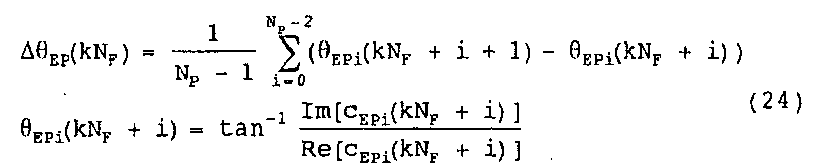
Thereafter, the DSP 26 executes average processing for
averaging the phase difference information ΔEP(kNF) in one burst
(step Z2). Concretely, the DSP 26 collects phase difference
information ΔEP(kNF) for the estimation period T from the
estimation time (m-1)T to the estimation time mT. If the number
of known signal blocks in the estimation period T is L, the DSP
26 obtains L of phase difference information ΔEP((m-1)LNF+lNF).
Herein, 1 shows the indication numbers which correspond one to
one known signal blocks, and is a value between 0 and (L-1)
(0≤1≤L-1).
Thereafter, as shown by Formula (25) below, the DSP 26
applies average processing to the collected L of phase
difference information ΔEP((m-1)LNF+lNF), whereby the average
phase difference EP1(mLNF) is determined as the first frequency
offset.

As described above, according to this Embodiment 5, the
average processing is executed by using only the phase
difference information. Therefore, the processing can be
simplified.
Fig. 15 is a flowchart for explanation of the first
frequency offset estimation processing relating to Embodiment
6 of the invention.
In the abovementioned Embodiment 1, the distortion
amounts cEPi(kNF+i) of the transmission channel are multiplied
by the complex conjugate and summed, whereby the phase
difference vector DEP(kNF) between adjacent known signals is
determined. On the other hand, in Embodiment 6, by applying DFT
processing to the distortion amounts cEPi(kNF+i) of the
transmission channel, the phase difference vector DEP(kNF) is
determined.
Concretely, the DSP 26 executes inter-symbol DFT
processing (step R1). More concretely, by applying the DFT
processing to the distortion amounts cEPi(kNF+i) of the
transmission channel, the DSP 26 determines signal electric
powers Pf1(n) corresponding to the plurality of frequency offset
candidates nΔfRES.
Still more concretely, as shown by Formula (26), within
the frequency offset estimating range fDET1 between -RS/2 and RS/2,
the DSP 26 rotates the phases of the distortion amounts
cEPi((m-1)LNF+lNF +i) of the transmission channel by the phase
amounts corresponding to the respective frequency offset
candidates nΔfRES. Thereafter, the DSP 26 vector-synthesizes the
distortion amounts cEPi((m-1)LNF+lNF +i) whose phases have been
rotated, and determines signal powers Pf1(n) corresponding to
the plurality of frequency offset candidates nΔfRES within the
frequency offset estimating range. In addition, in Formula (26)
below, n is approximately a value between -RS/(2ΔfRES) and
RS/(2ΔfRES).

Then, the DSP 26 vector-synthesizes the distortion
amounts cEPi(m-1)LNF+lNF +i) whose phases have been rotated, and
obtains signal powers Pf1(n) corresponding to the respective
plurality of frequency offset candidates nΔfRES.
Then, the DSP 26 executes window signal power operation
processing (step R2). Concretely, as shown by Formula (27), the
DSP 26 sums the signal powers Pf1(n) corresponding to the
frequency offset candidates nΔfRES in the window having a
frequency width of 2W1ΔfRES, whereby the window signal powers
Ef1(n) are determined.
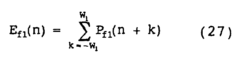
Thereafter, the DSP 26 executes maximum value detection
processing to detect the maximum value Ef1(nMAX) among the window
signal powers Ef1(n) (step R3), and executes phase difference
operation processing based on the detected maximum value
Ef1(nMAX) (step R4), whereby the phase difference EP1(mLNF) is
estimated as the first frequency offset.
As described above, according to Embodiment 6, frequency
offset candidates nΔfRES are set for each estimation accuracy
ΔfRES, signal powers Pf1(n) corresponding to the respective
frequency offset candidates nΔfRES are determined, and the
signal powers Pf1(n) are smoothed by using the frequency window,
whereby the first frequency offset is estimated. Therefore, for
example, if the estimation accuracies ΔfRES are finely set, the
estimation accuracy of the first frequency offset can be
improved.
Fig. 16 is a flowchart for explanation of the frequency
offset estimation processing relating to Embodiment 7 of the
invention.
In the abovementioned Embodiments 1 through 6, the
distortion amounts cEPi(kNF+i) of the transmission channel are
compensated based on the phase difference EP1(mLNF) as the first
frequency offset, and the phase difference EP2(mLNF) as the
second frequency offset based on the distortion amounts
cEPi(kNF+i) after being compensated is estimated.
Herein, the first frequency offset corresponds to the
frequency fD of the direct wave, and the frequency fD of the
direct wave exists near the center frequency fM of the Doppler
spread (see Fig. 9A). Therefore, on supposition that a certain
range around the frequency fD of the direct wave is a frequency
offset estimating range, it can be expected that the center
frequency fM of the Doppler spread exists within the range.
Therefore, in Embodiment 7, the frequency offset
estimating range for estimation of the second frequency offset
based on the first frequency offset is regulated.
Concretely, the DSP 26 detects the distortion amounts
cEPi(kNF+i) of the transmission channel (step Q1), and then
executes the first frequency offset estimation processing and
the second frequency offset estimation processing
simultaneously. More concretely, the DSP 26 estimates the first
frequency offset based on the abovementioned distortion amounts
CEPi(kNF+i) of the transmission channel. The DSP 26 temporarily
holds, for example, this first frequency offset.
In addition, the DSP 26 executes the first frequency
offset estimation processing and distortion amount average
processing simultaneously (step Q2). Concretely, the DSP 26
applies average processing to the distortion amounts cEPi(kNF+i)
of the transmission channel to determine the average distortion
amount cEP(kNF).
Thereafter, the DSP 26 executes DFT processing (steps Q3
and Q4). Concretely, the DSP 26 applies DFT processing to L of
average distortion amounts cEP((m+1)NF) in the estimation period
T (=LNFTS), and determines signal powers Pf(n) corresponding to
the plurality of frequency offset candidates nΔfRES
respectively.
More concretely, the DSP 26 sets a frequency offset
estimating range based on the first frequency offset (step Q3),
and determines signal powers Pf(n) corresponding to the
plurality of possible frequency offsets nΔfRES within the
frequency offset estimating range respectively (step Q4).
Still more concretely, the DSP 26 accords the first
frequency offset to any one of the frequency offset candidates
nΔfRES set in advance for each estimation accuracy ΔfRES. Herein,
the frequency offset candidate in accordance with the first
frequency offset is shown by NΔfRES. In addition, the DSP 26 sets
the range around this frequency offset candidate NΔfRES, that
is, the range between (-M+N)ΔfRES and (M+N)ΔfRES as the frequency
offset estimation range. M is the constant shown in Formula
(14).
Thereafter, as shown by Formula (28) below, based on the
phase amounts corresponding to the respective frequency offset
candidates ΔfRES within this set frequency offset estimation
range, the DSP 26 rotates the phases of the average distortion
amounts cEP((m+1)NF) (0≤1≤L-1). In Formula (28) below, n is a
value between (-M-W+N) and (M+W+N).

The DSP 26 vector-synthesizes the average distortion
amounts cEP((m+1)NF) whose phases have been rotated. Thereby,
the DSP 26 determines signal powers Pf(n) corresponding to the
plurality of frequency offset candidates nΔfRES respectively.
Thereafter, the DSP 26 determines window signal power
Ef(n) by cyclically summing the signal powers Pf(n) in a
frequency window with a predetermined frequency width (step Q5).
The DSP 26 determines the maximum value Ef(nMAX) of the window
signal power (step Q6), and estimates the frequency offset
candidate nΔfRES of this maximum value Ef(nMAX) as the last
frequency offset (step Q7).
As described above, according to Embodiment 7, the
frequency offset estimating range to estimate the frequency
offset based on the first frequency offset is set. Therefore,
the first frequency offset elimination processing and phase
synthesis processing become unnecessary. Therefore, the
processing can be simplified.
In addition, since the first frequency offset is
estimated in a relatively wide frequency offset estimating
range, a sufficient frequency offset compensating range is
secured. Also, since the center frequency of the Doppler spread
is used to estimate the last frequency offset, excellent BER
characteristics are secured. Therefore, the same effects as in
Embodiment 1 such as securing of a sufficient frequency offset
compensating range and prevention of deterioration in the BER
characteristics can also be obtained.
Fig. 17 is a flowchart for explanation of demodulation
processing relating to Embodiment 8 of the invention.
In Embodiment 1, the frequency offset elimination
processing in which the phase of the digital baseband signal
is rotated is executed after filtering processing. On the other
hand, in this Embodiment 8, the frequency offset elimination
processing is executed previous to the filtering processing.
Frequency offset of the receiving burst signal occurs due
to the stability of the oscillation circuit of the transmitter
1 and receiver 10 as explained in the subsection "Discription
of the Related Art" above. Particularly, in the case where
low-cost oscillation circuits are used, since the frequency
stability is low, great frequency offset occurs. In addition,
the frequency stability of the oscillation circuits is
influenced by the surrounding environment such as temperature
and changes in the power supply voltage.
Therefore, there is every possibility that the frequency
offset becomes greater in accordance with time elapse although
the offset is slight at the beginning. In this case, the
frequency bandwidth of the receiving burst signal may expand
to a large frequency bandwidth in comparison with the cutoff
frequency in the filtering processing. Therefore, a part of the
receiving burst signal may be cut by the filtering processing.
Accordingly, the data decision may not be sufficiently carried
out.
In view of the above circumstances, in this Embodiment
8, the frequency offset elimination processing is executed
prior to the filtering processing. Concretely, in this
Embodiment 8, the frequency offset elimination processing is
executed prior to the filtering processing, and distortion
amount detection processing, frequency offset estimation
processing, and integration processing are executed
simultaneously with sequential processing including fading
distortion compensation processing and data decision
processing.
More concretely, as shown in Fig. 17A, when digital
baseband signals are supplied from the A/ D converter circuits
25a and 25b, previous to the filtering processing, the DSP 26
executes frequency offset elimination processing (step P1).
Still more concretely, based on the accumulated phase
difference ((m-1)LNF+1NF+i) determined by the separately
executed integration processing, the phases of the digital
baseband signals are rotated in reverse. Thereby, digital
baseband signals from which frequency offset has been
eliminated are obtained.
Thereafter, the DSP 26 applies filtering processing to
the digital baseband signals (step P2) to eliminate noise
components and the like. Thereafter, the DSP 26 detects a
digital baseband signal corresponding to the Nyquist point
(step S3), eliminates fading distortion from the digital
baseband signal (step P4), and then executes data decision
processing (step P5).
On the other hand, as shown in Fig. 17B, the DSP 26 decides
whether or not the digital baseband signal corresponding to the
Nyquist point has been detected (step N1). If the Nyquist point
has been detected, based on the digital baseband signal
corresponding to the Nyquist point, the DSP 26 detects the
distortion amount cEPi(kNF+i) of the transmission channel (step
N2). Thereafter, based on the distortion amount cEPi(kNF+i) of
the transmission channel, the DSP 26 estimates the phase
difference S(mLNF) corresponding to the frequency offset (step
N3), and cyclically sums the phase differences S(mLNF), whereby
an accumulated phase difference ((m-1)LNF+lNF+i) is determined
(step N4). The DSP 26 uses this determined accumulated phase
difference ((m-1)LNF+lNF+i) for the frequency offset
elimination processing in step P1.
As described above, according to this Embodiment 8, the
frequency offset elimination processing is executed before the
filtering processing. Therefore, even if the frequency
bandwidths of the receiving burst signals are greater than the
cutoff frequency in the filtering processing, the frequency
offset can be eliminated while a part of the receiving burst
signals is not cut. Therefore, data decision can be
satisfactorily carried out.
Fig. 18 is a flowchart for explanation of demodulation
processing relating to Embodiment 9 of the invention.
In the abovementioned Embodiments 1 through 8, by
directly rotating the phase of the digital baseband signal, the
frequency offset is compensated. On the other hand, in this
Embodiment 9, the phase of the receiving burst signal is rotated
by changing the frequency of the local oscillation signal
generated at the oscillation circuit 22, whereby the frequency
offset is compensated.
Concretely, in this Embodiment 9, digital signal
processing by way of software is not applied to the digital
baseband signal, but a voltage to be applied to the oscillation
circuit 22 comprised of VCO is controlled to eliminate the
frequency offset.
That is, in this Embodiment 9, as shown in Fig. 18A,
filtering processing (step M1), Nyquist point detection
processing (step M2), fading distortion compensation
processing (step M3), and data decision processing (step M4)
are executed, and simultaneously with these sequential
processings, as shown in Fig. 18B, distortion amount detection
processing, frequency offset estimation processing, and VCO
control processing for controlling the voltage to be applied
to the VCO 22 are executed.
More concretely, the DSP 26 decides whether or not the
digital baseband signal corresponding to the Nyquist point has
been detected (step L1). In the case where the Nyquist point
has been detected, the DSP 26 detects the distortion amount
cEPi(kNF+i) of the transmission channel based on the digital
baseband signal corresponding to the Nyquist point (step L2).
Thereafter, the DSP 26 estimates frequency offset based on the
distortion amount cEPi(kNF+i) of the transmission channel (step
L3). Then, the DSP 26 supplies a voltage in accordance with the
estimated frequency offset to the VCO 22 (step L4).
Thereby, the VCO 22 oscillates a local oscillation signal
having an oscillation frequency which has deviated by an amount
according to the frequency offset from the original oscillation
frequency. Therefore, the frequency converter circuit 21
outputs an analog baseband signal from which frequency offset
has been eliminated. Thus, excellent frequency offset
compensation can be realized.
As described above, according to Embodiment 9, by
adjusting the frequency of the local oscillation signal
generated by the VCO 22, the frequency offset is eliminated from
the receiving IF signal. That is, before the filtering
processing by the DSP 26, the frequency offset is eliminated.
Therefore, as in the abovementioned Embodiment 8, even if the
frequency bandwidth of the receiving burst signal expands to
be larger than the cutoff frequency in the filtering processing,
frequency offset can be eliminated while a part of the receiving
burst signal is not cut. Therefore, the data decision can be
satisfactorily carried out.
Fig. 19 is a flowchart for explanation of demodulation
processing relating to Embodiment 10 of the invention.
In the abovementioned Embodiment 1, the first frequency
offset and the second frequency offset are synthesized to
estimate the last frequency offset, and in accordance with this
frequency offset, compensation for the frequency offset is
carried out, whereby the frequency of the digital baseband
signal is automatically controlled. On the other hand, in this
Embodiment 10, frequency offset compensation in accordance with
the first frequency offset is carried out for the digital
baseband signals, and frequency offset compensation in
accordance with the second frequency offset is carried out for
digital baseband signals after the abovementioned compensation
is carried out, whereby the frequency of the digital baseband
signal is automatically controlled.
Concretely, the DSP 26 applies predetermined filtering
processing to the digital baseband signals (step K1), and then
detects a digital baseband signal corresponding to Nyquist
point (step K2). Next, the DSP 26 executes the first automatic
frequency control processing (hereinafter, referred to as the
first AFC processing) for the digital baseband signal (step K3),
and then executes the second automatic frequency control
processing (hereinafter, referred to as the second AFC
processing) for the digital baseband signal after being
subjected to the first AFC processing (step K4). Then, the DSP
26 executes fading distortion compensation processing for the
digital baseband signal after being subjected to the second AFC
processing (step K5), and applies data decision processing to
the signal (step K6), whereby data corresponding to the original
information signal is restored.
Fig. 20 is a flowchart for explanation of the first AFC
processing. The DSP 26 detects the distortion amounts cEPi(kNF+i)
of the transmission channel for each symbol (step J1), and then
executes the first frequency offset estimation processing (step
J2). The first frequency offset estimation processing is the
same as that in the abovementioned Embodiment 1, and by this
processing, the DSP 26 estimates the phase difference EP1(mLNF)
as the first frequency offset corresponding to the phase
rotation amount for one symbol.
Thereafter, the DSP 26 executes integration processing
for cyclically summing the phase differences EP1(mLNF) (step
J3) to obtain an accumulated phase difference 1((m-1)LNF+lNF+i).
In this case, the DSP 26 obtains the phase difference
1((m-1)LNF+lNF+i) accumulated from the estimation time mT for
each symbol period TS.
Thereafter, the DSP 26 executes the first frequency
offset elimination processing (step J4). Concretely, based on
the accumulated phase difference 1((m-1)LNF+lNF+i), the DSP 26
rotates in reverse the phase of the digital baseband signal
r(kNF+i) by an amount in accordance with the accumulated phase
difference 1((m-1)LNF+lNF+i). Thereby, the first frequency
offset can be eliminated from the digital baseband signal
r(kNF+i). Thus, the DSP 26 achieves automatic frequency control
of the digital baseband signals r(kNF+i) based on the first
frequency offset.
Fig. 21 is a flowchart for explanation of the second AFC
processing. Based on the known signal blocks of the digital
baseband signal after being subjected to the first AFC
processing, the DSP 26 detects the distortion amount cEPi2(kNF+i)
of the transmission channel for each symbol in the known signal
blocks (step I1).
Thereafter, based on the detected distortion amount
cEPi2(kNF+i) of the transmission channel, the DSP 26 executes the
second frequency offset estimation processing that is the same
as in Embodiment 1 (step I2). Thereby, the DSP 26 estimates the
phase difference EP2(mLNF) as the second frequency offset
corresponding to the phase rotation amount for one symbol.
Thereafter, the DSP 26 executes integration processing
for cyclically summing the phase differences EP2(mLNF) (step
I3), and obtains an accumulated phase difference 2((m-1)LNF+lNF+i).
In this case, the DSP 26 obtains the phase
difference 2((m-1)LNF+1NF+i) accumulated from the estimation
time mT for each symbol period TS.
Thereafter, the DSP 26 executes the second frequency
offset elimination processing (step I4). Concretely, based on
the accumulated phase difference 2((m-1)LNF+lNF+i), the DSP 26
rotates in reverse the phase of the digital baseband signal
rR1(kNF+i) by an amount according to the accumulated phase
difference 2((m-1)LNF+lNF+i). Thereby, the second frequency
offset can be eliminated from the digital baseband signal
rR1(kNF+i). Thus, the DSP 26 achieves automatic frequency
control of the digital baseband signal rR1(kNF+i) based on the
second frequency offset.
As described above, according to this Embodiment 10,
compatibility of securing of a sufficient frequency offset
compensating range and securing of excellent BER
characteristics is also achieved.
Fig. 22 is a flowchart for explanation of demodulation
processing relating to Embodiment 11 of the invention.
In the abovementioned Embodiment 10, the frequency offset
elimination processing is executed after the filtering
processing. On the other hand, in this Embodiment 11, the
frequency offset elimination processing is executed before the
filtering processing.
Concretely, in this Embodiment 11, the first frequency
offset elimination processing that is a part of the first AFC
processing is executed before the filtering processing, and the
remaining processing of the first AFC processing, that is,
distortion amount detection processing, the first frequency
offset estimation processing, and integration processing are
executed simultaneously with sequential processing.
More concretely, as shown in Fig. 22A, when the digital
baseband signals are supplied from the A/ D converter circuits
25a and 25b, and previous to the filtering processing, the DSP
26 executes the first frequency offset elimination processing
(step H1). Still more concretely, the DSP 26 rotates in reverse
the phases of the digital baseband signals by amounts according
to the accumulated phase difference ((m-1)LNF+lNF+i)
corresponding to the first frequency offset determined by the
integration processing executed simultaneously with the
sequential processing. Thereby, digital baseband signals from
which first frequency offset has been eliminated are obtained.
Thereafter, the DSP 26 applies filtering processing to
the digital baseband signals (step H2) to eliminate noise
components and the like, and then detects a digital baseband
signal corresponding to the Nyquist point (step H3). Thereafter,
the DSP 26 executes the second AFC processing based on the
digital baseband signal (step H4). By executing this second AFC
processing, the DSP 26 can obtain a digital baseband signal in
which the last frequency offset has been eliminated. Next, the
DSP 26 eliminates fading distortion from the digital baseband
signal (step H5), and then executes data decision processing
(step H6).
On the other hand, as shown in Fig. 22B, the DSP 26 decides
whether or not the digital baseband signal corresponding to the
Nyquist point has been detected (step G1). In the case where
the Nyquist point has been detected, based on the digital
baseband signal corresponding to the Nyquist point, the DSP 26
detects the distortion amount cEPi(kNF+i) of the transmission
path (step G2). Thereafter, based on the distortion amount
cEPi(kNF+i) of the transmission channel, the DSP 26 estimates
the phase difference S(mLNF) corresponding to the first
frequency offset (step G3), and cyclically sums the phase
differences S(mLNF), whereby an accumulated phase difference
((m-1)LNF+lNF+i) is determined (step G4). The DSP 26 uses this
determined accumulated phase difference ((m-1)LNF+lNF+i) for
the first frequency offset elimination processing in step H1.
As described above, according to this Embodiment 11, the
first frequency offset elimination processing is executed
before the filtering processing. Therefore, even when the
frequency bandwidth of the receiving IF signal becomes larger
than the cutoff frequency in the filtering processing, the first
frequency offset can be eliminated while a part of the receiving
IF signals is not cut. Therefore, data decision can be
satisfactorily carried out.
Fig. 23 is a flowchart for explanation of demodulation
processing relating to Embodiment 12 of the invention.
In the abovementioned Embodiment 10, by directly rotating
the phase of the digital baseband signal, the frequency offset
is compensated. On the other hand, in this Embodiment 12, by
adjusting the frequency of the local oscillation signal
generated by the oscillation circuit 22 that is the VCO, the
phase of the receiving burst signal is rotated, whereby the
frequency offset is compensated.
Concretely, in this Embodiment 12, digital signal
processing by way of software is not applied to the digital
baseband signal, but the voltage to be applied to the
oscillation circuit 22 formed of the VCO is controlled, whereby
the frequency offset is eliminated.
That is, in this Embodiment 12, as shown in Fig. 23A, the
filtering processing (step F1), Nyquist point detection
processing (step F2), the second AFC processing (step F3),
fading distortion compensation processing (step F4), and data
decision processing (step F5) are executed, and simultaneously
with these sequential processings, as shown in Fig. 23B,
distortion amount detection processing, the first frequency
offset estimation processing, and VCO control processing for
controlling the voltage to be applied to the VCO 22 are executed.
Concretely, the DSP 26 decides whether or not the digital
baseband signal corresponding to the Nyquist point has been
detected (step E1). In the case where the Nyquist point has been
detected, based on the digital baseband signal corresponding
to the Nyquist point, the DSP 26 detects the distortion amount
cEPi(kNF+i) of the transmission channel (step E2). Thereafter,
the DSP 26 estimates the first frequency offset based on the
distortion amount cEPi(kNF+i) of the transmission channel (step
E3). Then, the DSP 26 applies a voltage according to the
estimated first frequency offset to the VCO 22 (step E4).
Thereby, the VCO 22 oscillates the local oscillation
signal having an oscillation frequency deviated by an amount
in accordance with the first frequency offset from the original
oscillation frequency. Therefore, the frequency converter
circuit 21 outputs analog baseband signals in which the first
frequency offset has been eliminated. Thus, excellent frequency
offset compensation can be realized.
As described above, according to this Embodiment 12, by
adjusting the frequency of the local oscillation signal
generated by the VCO 22, frequency offset is eliminated from
the receiving IF signal. That is, the first frequency offset
is eliminated before the filtering processing. Therefore, as
in the abovementioned Embodiment 11, even when the frequency
bandwidth of the receiving IF signal expands to be larger than
the cutoff frequency in the filtering processing, frequency
offset can be eliminated while a part of the receiving IF signal
is not cut. Therefore, data decision can be satisfactorily
carried out.
The Embodiments of the invention are as described above,
however, the invention is not limited to the abovementioned
Embodiments. For example, in the Embodiments, the case where
the TDMA is applied as the communications method is described.
However, as the communications method, the FDMA (Frequency
Division Multiple Access), CDMA (Code Division Multiple Access),
or the like may be applied. In such a case, the radio receiving
signals are not burst signals but are continuous signals as in
the case where TDMA is applied. However, needless to say, the
invention can be easily applied even to this case.
In addition, in the abovementioned Embodiments, the case
where the demodulation processing is realized by way of software
by the DSP 26 is described. However, of course, the steps of
the demodulation processing to be executed by the DSP 26 may
be realized by hardware circuits.
Claims (14)
- An automatic frequency control method for controlling the frequency of a radio receiving signal by compensating frequency offset of the radio receiving signal periodically including a plurality of adjacent known signals, wherein the frequency of the direct wave of the radio receiving signal and the center frequency of the Doppler spread of the radio receiving signal are estimated based on the distortion amounts of the known signals included in the radio receiving signal, and the frequency offset of the radio receiving signal is compensated based on both of these frequencies.
- An automatic frequency control method according to claim 1, wherein the radio receiving signal is a burst signal synchronized with a predetermined time slot in the TDMA.
- An automatic frequency control method for controlling the frequency of a radio receiving signal by eliminating frequency offset from the radio receiving signal periodically including a plurality of adjacent known signals, comprising:a frequency offset estimating step for estimating frequency offset of the radio receiving signal from the frequency of the direct wave of the radio receiving signal, which is estimated based on the distortion amounts of the known signals included in the radio receiving signal, and the center frequency of the Doppler spread of the radio receiving signal; anda frequency offset eliminating step for eliminating the estimated frequency offset from the radio receiving signal.
- An automatic frequency control method according to claim 3, wherein the frequency offset estimating step includes:a distortion amount operating step for determining the distortion amounts of the known signals included in the radio receiving signal;a first frequency offset estimating step for estimating the frequency of the direct wave of the radio receiving signal based on the distortion amounts between adjacent known signals among these determined distortion amounts;a distortion amount frequency offset eliminating step for eliminating frequency offset from the distortion amounts of the known signals based on the estimated frequency of the direct wave;a second frequency offset estimating step for estimating the center frequency of the Doppler spread of the radio receiving signal based on the distortion amounts between the periodically inserted known signals among the distortion amounts from which the frequency offset has been eliminated; anda synthesizing step for synthesizing the phase amount corresponding to the frequency of the direct wave and the phase amount corresponding to the center frequency of the Doppler broadening to estimate frequency offset of the radio receiving signal.
- An automatic frequency control method according to claim 4, wherein the first frequency offset estimating step includes steps of:determining the phase difference vectors based on the distortion amounts between adjacent known signals among the determined distortion amounts;determining the average phase difference vector by averaging the determined phase difference vectors for a predetermined period; andestimating the frequency of the direct wave based on the determined average phase difference vector.
- An automatic frequency control method according to claim 4, wherein the second frequency offset estimating step includes steps of:determining the average distortion amount by averaging the distortion amounts from which frequency offset has been eliminated;determining signal powers corresponding to a plurality of frequency offset candidates set at each predetermined interval within a predetermined frequency offset estimating range based on the determined average distortion amount;determining the window signal power of all frequency offset candidates within the frequency offset estimating range by summing the signal powers of the frequency offset candidates in the frequency window with a predetermined frequency width among the determined signal powers; andestimating the frequency offset candidate corresponding to the maximum value of the determined window signal power as the center frequency of the Doppler spread.
- An automatic frequency control method according to claim 4, wherein the first frequency offset estimating step includes steps of:determining phase difference information based on the distortion amounts between the adjacent known signals among the distortion amounts;determining average phase difference information by averaging the determined phase difference information for a predetermined period; andestimating the frequency of the direct wave based on the determined average phase difference information.
- An automatic frequency control method according to claim 4, wherein the first frequency offset estimating step includes steps of:determining signal powers corresponding to a plurality of frequency offset candidates set at each predetermined interval in a predetermined frequency offset estimating range based on the distortion amounts of the adjacent known signals among the distortion amounts;determining window signal powers corresponding to all frequency offset candidates by summing signal powers corresponding to the frequency offset candidates in a frequency windows with predetermined frequency widths among the determined signal powers; andestimating the frequency offset candidate corresponding to the maximum value of the determined window signal powers as the frequency of the direct wave.
- An automatic frequency control method according to claim 3, wherein the frequency offset estimating step includes:a distortion amount operating step for determining distortion amounts of the known signals included in the radio receiving signal;a first frequency offset estimating step for estimating the frequency of the direct wave of the radio receiving signal based on the distortion amounts between the adjacent known signals among the determined distortion amounts;an average distortion amount operating step for determining the average distortion amount by averaging the determined distortion amounts;a signal power operating step for determining signal powers corresponding to a plurality of frequency offset candidates set at each predetermined interval in a frequency offset estimating range regulated by the estimated frequency of the direct wave based on the determined average distortion amount;a window signal power operating step for determining window signal powers of all frequency offset candidates in the frequency offset estimating range by summing the signal powers of the frequency offset candidates in the frequency window with a predetermined frequency width among the determined signal powers; anda second frequency offset estimating step for estimating the frequency offset candidate corresponding to the maximum value of the determined window singal powers as the frequency offset of the radio receiving signal.
- An automatic frequency control method according to claim 3, further comprising a filtering step for eliminating high frequency components over the cutoff frequency from the radio receiving signal, whereinthe frequency offset estimating step is for determining the distortion amounts of the known signals by using the radio receiving signal from which the high frequency components have been eliminated; andthe frequency offset eliminating step is for eliminating the estimated frequency offset from the radio receiving signal whose high frequency components have not been eliminated by the filtering step.
- An automatic frequency control method for controlling the frequency of a radio receiving signal by eliminating frequency offset from the radio receiving signal periodically including a plurality of adjacent known signals, comprising:a first distortion amount operating step for determining the distortion amounts between the known signals included in the radio receiving signal;a first frequency offset estimating step for estimating the frequency of the direct wave of the radio receiving signal based on the distortion amounts of the adjacent known signals among the determined distortion amounts;a first frequency offset eliminating step for eliminating frequency offset corresponding to the estimated frequency of the direct wave from the radio receiving signal;a second distortion amount operating step for determining the distortion amounts of the known signals included in the radio receiving signal from which the frequency offset has been eliminated;a second frequency offset estimating step for estimating the center frequency of the Doppler spread of the radio receiving signal based on the distortion amounts between the periodically included known signal blocks among the determined distortion amounts;a second frequency offset eliminating step for eliminating frequency offset corresponding to the estimated center frequency of the Doppler spread from the radio receiving signal.
- An automatic frequency control divice for controlling the frequency of a digital baseband signal by eliminating frequency offset from the digital baseband signal upon receiving the digital baseband signal outputted from an A/D converter as an input corresponding to a radio receiving signal which periodically includes a plurality of adjacent known signals, wherein the frequency of the direct wave of the radio receiving signal and the center frequency of the Doppler spread of the radio receiving signal are estimated based on the distortion amounts of the known signals included in the digital baseband signal, and frequency offset is eliminated from the digital baseband signal based on both frequencies.
- A demodulator, comprising:a frequency converter circuit for converting a radio receiving signal periodically including a plurality of adjacent known signals into an analog baseband signal;an A/D converter circuit for converting this analog baseband signal into a digital baseband signal;a digital signal processing device, which receives the digital baseband signal generated by the A/D converter circuit as an input, estimates the frequency of the direct wave of the radio receiving signal and the center frequency of the Doppler spread of the radio receiving signal based on the distortion amounts of the known signals included in the inputted digital baseband signal, eliminates frequency offset from the digital baseband signal based on both frequencies, and eliminates fading distortion from the digital baseband signal from which the frequency offset has been eliminated and then demodulates the digital baseband signal.
- A demodulator according to claim 13, whereinthe frequency converter circuit has a voltage control oscillation part, which oscillates a local oscillation signal for converting the radio receiving signal into an analog baseband signal, and changes the oscillation frequency of the oscillation signal in accordance with an applied voltage; andthe digital signal processing device eliminates frequency offset from the digital baseband signal by applying a voltage in accordance with both of the estimated frequencies to the voltage control oscillation part.
Applications Claiming Priority (1)
| Application Number | Priority Date | Filing Date | Title |
|---|---|---|---|
| PCT/JP2000/002123 WO2001076097A1 (en) | 2000-03-31 | 2000-03-31 | Method and apparatus for automatic frequency control and demodulator |
Publications (2)
| Publication Number | Publication Date |
|---|---|
| EP1180853A1 true EP1180853A1 (en) | 2002-02-20 |
| EP1180853A4 EP1180853A4 (en) | 2006-06-07 |
Family
ID=11735871
Family Applications (1)
| Application Number | Title | Priority Date | Filing Date |
|---|---|---|---|
| EP00913061A Withdrawn EP1180853A4 (en) | 2000-03-31 | 2000-03-31 | METHOD AND APPARATUS FOR AUTOMATIC FREQUENCY REGULATION AND DEMODULATOR |
Country Status (5)
| Country | Link |
|---|---|
| US (1) | US6983134B1 (en) |
| EP (1) | EP1180853A4 (en) |
| JP (1) | JP3910448B2 (en) |
| CN (1) | CN1350729A (en) |
| WO (1) | WO2001076097A1 (en) |
Cited By (2)
| Publication number | Priority date | Publication date | Assignee | Title |
|---|---|---|---|---|
| EP1450497A3 (en) * | 2003-02-21 | 2004-12-08 | Fujitsu Limited | Communications device with Doppler frequency estimation functions |
| US8326257B2 (en) | 2002-10-28 | 2012-12-04 | Qualcomm Incorporated | Utilizing speed and position information to select an operational mode in a wireless communication system |
Families Citing this family (12)
| Publication number | Priority date | Publication date | Assignee | Title |
|---|---|---|---|---|
| US6912244B2 (en) * | 2002-01-31 | 2005-06-28 | Qualcomm Inc. | Pilot frequency acquisition based on a window of data samples |
| JP2003283385A (en) * | 2002-03-25 | 2003-10-03 | Hitachi Kokusai Electric Inc | Equalizer |
| JP2003347977A (en) * | 2002-05-22 | 2003-12-05 | Hitachi Kokusai Electric Inc | Equalizer |
| US7323883B2 (en) * | 2003-05-23 | 2008-01-29 | Advantest Corporation | Phase measurement device, method, program, and recording medium |
| WO2005027353A2 (en) * | 2003-09-12 | 2005-03-24 | Ems Technologies Canada, Ltd. | Hybrid frequency offset estimator |
| JP4563278B2 (en) * | 2005-08-03 | 2010-10-13 | 三菱電機株式会社 | Automatic frequency controller |
| WO2007064323A1 (en) * | 2005-12-01 | 2007-06-07 | Thomson Licensing | Method and apparatus for determining frequency offset in a receiver |
| TWI302066B (en) * | 2006-04-26 | 2008-10-11 | Ind Tech Res Inst | Frequency acquisition and tracking circuit |
| JP6635289B2 (en) * | 2015-09-01 | 2020-01-22 | 株式会社レイトロン | Wireless receiving device and received data restoring device |
| CN105891852B (en) * | 2015-12-29 | 2018-05-29 | 中国科学院国家天文台 | The navigation signal reception device and satellite navigation system that a kind of frequency point can flexibly be set |
| CN107094042B (en) * | 2016-02-18 | 2020-09-25 | 中国移动通信集团公司 | Channel information indication method, system and receiver device |
| JP6845044B2 (en) * | 2017-03-03 | 2021-03-17 | 株式会社モバイルテクノ | Wireless communication device and frequency offset compensation method |
Family Cites Families (16)
| Publication number | Priority date | Publication date | Assignee | Title |
|---|---|---|---|---|
| FR2633471B1 (en) * | 1988-06-28 | 1990-10-05 | Trt Telecom Radio Electr | METHOD OF CONSISTENT DEMODULATION OF A DIGITALLY MODULATED SIGNAL IN CONTINUOUS PHASE AND WITH A CONSTANT ENVELOPE |
| CA2071421C (en) * | 1991-06-19 | 2000-08-08 | Yoshiaki Kumagai | Automatic frequency control circuit |
| US5263026A (en) * | 1991-06-27 | 1993-11-16 | Hughes Aircraft Company | Maximum likelihood sequence estimation based equalization within a mobile digital cellular receiver |
| JP2531353B2 (en) * | 1993-07-21 | 1996-09-04 | 日本電気株式会社 | Wireless receiver |
| FI96257C (en) | 1994-04-13 | 1996-05-27 | Nokia Telecommunications Oy | A method for determining the phase error of a radio frequency signal, as well as a receiver |
| JPH08307375A (en) * | 1995-05-11 | 1996-11-22 | Kokusai Denshin Denwa Co Ltd <Kdd> | Modulation signal spread spectrum communication method using chirp signal |
| JPH09214569A (en) * | 1996-02-02 | 1997-08-15 | Hitachi Ltd | FSK baseband demodulator and mobile communication system |
| JPH1051356A (en) * | 1996-03-29 | 1998-02-20 | Matsushita Electric Ind Co Ltd | Doppler frequency measurement circuit and synchronization circuit |
| JPH10313286A (en) * | 1997-05-13 | 1998-11-24 | Sony Corp | Receiver |
| US5999561A (en) * | 1997-05-20 | 1999-12-07 | Sanconix, Inc. | Direct sequence spread spectrum method, computer-based product, apparatus and system tolerant to frequency reference offset |
| JPH1168630A (en) * | 1997-08-19 | 1999-03-09 | Yuseisho Tsushin Sogo Kenkyusho | Propagation path distortion compensating method |
| JP3335887B2 (en) * | 1997-08-20 | 2002-10-21 | 松下電器産業株式会社 | Spread spectrum demodulator and spread spectrum demodulation method |
| JP3316744B2 (en) * | 1997-10-30 | 2002-08-19 | 三菱電機株式会社 | AFC circuit, receiver having the same, and automatic frequency control communication system |
| JPH11205092A (en) * | 1998-01-20 | 1999-07-30 | Nippon Telegr & Teleph Corp <Ntt> | AFC circuit for equalizer |
| US6590945B1 (en) * | 1999-07-13 | 2003-07-08 | Lucent Technologies Inc. | Method and apparatus for frequency offset compensation |
| US6606363B1 (en) * | 1999-12-28 | 2003-08-12 | Telefonaktiebolaget Lm Ericsson (Publ) | Method and apparatus for estimating a frequency offset by combining pilot symbols and data symbols |
-
2000
- 2000-03-31 CN CN00807590.5A patent/CN1350729A/en active Pending
- 2000-03-31 JP JP2001573659A patent/JP3910448B2/en not_active Expired - Fee Related
- 2000-03-31 WO PCT/JP2000/002123 patent/WO2001076097A1/en not_active Ceased
- 2000-03-31 EP EP00913061A patent/EP1180853A4/en not_active Withdrawn
- 2000-03-31 US US09/926,556 patent/US6983134B1/en not_active Expired - Fee Related
Cited By (4)
| Publication number | Priority date | Publication date | Assignee | Title |
|---|---|---|---|---|
| US8326257B2 (en) | 2002-10-28 | 2012-12-04 | Qualcomm Incorporated | Utilizing speed and position information to select an operational mode in a wireless communication system |
| US8700020B2 (en) | 2002-10-28 | 2014-04-15 | Qualcomm Incorporated | Utilizing speed and position information to select an operational mode in a wireless communication system |
| EP1450497A3 (en) * | 2003-02-21 | 2004-12-08 | Fujitsu Limited | Communications device with Doppler frequency estimation functions |
| US7349483B2 (en) | 2003-02-21 | 2008-03-25 | Fujitsu Limited | Communications device with doppler frequency estimation functions |
Also Published As
| Publication number | Publication date |
|---|---|
| CN1350729A (en) | 2002-05-22 |
| WO2001076097A1 (en) | 2001-10-11 |
| EP1180853A4 (en) | 2006-06-07 |
| JP3910448B2 (en) | 2007-04-25 |
| US6983134B1 (en) | 2006-01-03 |
Similar Documents
| Publication | Publication Date | Title |
|---|---|---|
| EP1057282B1 (en) | Automatic frequency control loop multipath combiner for a rake receiver | |
| US6631174B1 (en) | Automatic frequency control apparatus | |
| US5692015A (en) | Coherent detector and a coherent detection method for a digital communication receiver | |
| USRE42538E1 (en) | System and method for signal synchronization in a communication system | |
| EP1180853A1 (en) | Method and apparatus for automatic frequency control and demodulator | |
| US5936961A (en) | Signalling packet for communication system with reference modulated in accordance with a time-dependent law | |
| EP1056249B1 (en) | Multicarrier receiver with noise detection and frequency control | |
| US6725024B1 (en) | Offset local oscillator frequency | |
| US6519300B1 (en) | System and method for automatic frequency correction in a pilot symbol assisted demodulator | |
| US6353642B1 (en) | Automatic frequency controller and demodulator unit | |
| FI102338B (en) | Receiver synchronization in idle mode | |
| US7313125B2 (en) | OFDM demodulation method and semiconductor integrated circuit device | |
| JPWO2001001590A1 (en) | Automatic frequency control circuit and demodulator | |
| JPWO2001076097A1 (en) | Automatic frequency control method and apparatus, and demodulation device | |
| WO1993019548A1 (en) | Apparatus for and method of synchronizing a clock signal | |
| EP0751644B1 (en) | Control signal detection method with calibration error and subscriber unit therewith | |
| WO2005117433A1 (en) | Apparatus and method for corresponding frequency synchronization in on-channel repeater | |
| US5255292A (en) | Method and apparatus for modifying a decision-directed clock recovery system | |
| US7706823B2 (en) | Method and system for synchronizing a base station of a wireless communication system and a subscriber communication equipment | |
| KR100341200B1 (en) | Quadrature frequency division multiplexing demodulator | |
| US5497402A (en) | Automatic frequency control device for satellite communications ground system | |
| EP1459441A4 (en) | Fast timing acquisition for multiple radio terminals | |
| US7474718B2 (en) | Frequency control for a mobile communications device | |
| US6697609B2 (en) | Carrier reproducing apparatus and method of the same | |
| JP2024063824A (en) | Radio communications system |
Legal Events
| Date | Code | Title | Description |
|---|---|---|---|
| PUAI | Public reference made under article 153(3) epc to a published international application that has entered the european phase |
Free format text: ORIGINAL CODE: 0009012 |
|
| 17P | Request for examination filed |
Effective date: 20011105 |
|
| AK | Designated contracting states |
Kind code of ref document: A1 Designated state(s): AT BE CH CY DE DK ES FI FR GB GR IE IT LI LU MC NL PT SE |
|
| RBV | Designated contracting states (corrected) |
Designated state(s): DE FR GB IT |
|
| RAP1 | Party data changed (applicant data changed or rights of an application transferred) |
Owner name: MITSUBISHI DENKI KABUSHIKI KAISHA |
|
| A4 | Supplementary search report drawn up and despatched |
Effective date: 20060503 |
|
| STAA | Information on the status of an ep patent application or granted ep patent |
Free format text: STATUS: THE APPLICATION HAS BEEN WITHDRAWN |
|
| 18W | Application withdrawn |
Effective date: 20060519 |