EP1180670A1 - Temperature sensor mounting structure - Google Patents
Temperature sensor mounting structure Download PDFInfo
- Publication number
- EP1180670A1 EP1180670A1 EP01119236A EP01119236A EP1180670A1 EP 1180670 A1 EP1180670 A1 EP 1180670A1 EP 01119236 A EP01119236 A EP 01119236A EP 01119236 A EP01119236 A EP 01119236A EP 1180670 A1 EP1180670 A1 EP 1180670A1
- Authority
- EP
- European Patent Office
- Prior art keywords
- temperature sensor
- mounting structure
- sealing member
- mounting seat
- fixing member
- Prior art date
- Legal status (The legal status is an assumption and is not a legal conclusion. Google has not performed a legal analysis and makes no representation as to the accuracy of the status listed.)
- Granted
Links
- 239000007789 gas Substances 0.000 claims description 41
- 238000007789 sealing Methods 0.000 claims description 18
- 239000012530 fluid Substances 0.000 claims description 9
- 239000002184 metal Substances 0.000 claims description 6
- 229910052751 metal Inorganic materials 0.000 claims description 6
- WABPQHHGFIMREM-UHFFFAOYSA-N lead(0) Chemical compound [Pb] WABPQHHGFIMREM-UHFFFAOYSA-N 0.000 claims description 5
- 241001247986 Calotropis procera Species 0.000 claims description 3
- 238000007254 oxidation reaction Methods 0.000 claims description 2
- 210000002445 nipple Anatomy 0.000 abstract description 44
- 230000008602 contraction Effects 0.000 abstract description 16
- 238000010276 construction Methods 0.000 abstract description 8
- 239000000463 material Substances 0.000 description 8
- 238000010586 diagram Methods 0.000 description 6
- 230000003197 catalytic effect Effects 0.000 description 5
- 229910001220 stainless steel Inorganic materials 0.000 description 5
- 239000010935 stainless steel Substances 0.000 description 5
- XEEYBQQBJWHFJM-UHFFFAOYSA-N Iron Chemical compound [Fe] XEEYBQQBJWHFJM-UHFFFAOYSA-N 0.000 description 4
- 238000005219 brazing Methods 0.000 description 4
- 238000003466 welding Methods 0.000 description 4
- 229910000831 Steel Inorganic materials 0.000 description 2
- 238000002485 combustion reaction Methods 0.000 description 2
- 229910052742 iron Inorganic materials 0.000 description 2
- 239000010959 steel Substances 0.000 description 2
- 241001232202 Chrysothamnus stylosus Species 0.000 description 1
- 239000004809 Teflon Substances 0.000 description 1
- 229920006362 Teflon® Polymers 0.000 description 1
- 229910001566 austenite Inorganic materials 0.000 description 1
- 238000005452 bending Methods 0.000 description 1
- 239000000919 ceramic Substances 0.000 description 1
- 239000000470 constituent Substances 0.000 description 1
- 230000007797 corrosion Effects 0.000 description 1
- 238000005260 corrosion Methods 0.000 description 1
- 230000003247 decreasing effect Effects 0.000 description 1
- 238000009826 distribution Methods 0.000 description 1
- 238000003780 insertion Methods 0.000 description 1
- 230000037431 insertion Effects 0.000 description 1
- 238000009413 insulation Methods 0.000 description 1
- 229910000734 martensite Inorganic materials 0.000 description 1
- 150000002739 metals Chemical class 0.000 description 1
- 230000000149 penetrating effect Effects 0.000 description 1
- 230000001737 promoting effect Effects 0.000 description 1
- 238000006479 redox reaction Methods 0.000 description 1
- 239000011347 resin Substances 0.000 description 1
- 229920005989 resin Polymers 0.000 description 1
- 125000006850 spacer group Chemical group 0.000 description 1
- BFKJFAAPBSQJPD-UHFFFAOYSA-N tetrafluoroethene Chemical group FC(F)=C(F)F BFKJFAAPBSQJPD-UHFFFAOYSA-N 0.000 description 1
- 229910000859 α-Fe Inorganic materials 0.000 description 1
Images




Classifications
-
- G—PHYSICS
- G01—MEASURING; TESTING
- G01K—MEASURING TEMPERATURE; MEASURING QUANTITY OF HEAT; THERMALLY-SENSITIVE ELEMENTS NOT OTHERWISE PROVIDED FOR
- G01K13/00—Thermometers specially adapted for specific purposes
- G01K13/02—Thermometers specially adapted for specific purposes for measuring temperature of moving fluids or granular materials capable of flow
Definitions
- the present invention relates to a mounting structure, for a temperature sensor for detecting the temperature of fluid flowing through a tube, and the mounting structure according to the present invention is effective when applied to a mounting structure for an exhaust gas temperature sensor for detecting the temperature of exhaust gas discharged from a heat engine such as an internal combustion engine.
- Fig. 2A is a typical diagram showing the mounting structure of a temperature sensor (an exhaust gas temperature sensor) 100
- Fig. 2B is an enlarged view of a portion A in Fig. 2A.
- the temperature sensor 100 is fixedly threaded to a boss portion 201 welded to an exhaust pipe 200.
- reference numeral 103 denotes a cover for protecting a sensor main body such as a thermistor
- reference numeral 104 denotes a sheath pin for protecting a sheath pin core wire which is electrically joined to the sensor main body
- reference numeral 105 denotes a rib adapted to be brought into contact with the boss portion 201 for preventing exhaust gas from leaking from a portion where the temperature sensor 100 is mounted to the outside, and this rib 105 is joined to the sheath pin 104.
- a nipple nut 106 having external threads formed thereon is thread fastened to an internal thread portion of the boss portion 201, so that the rib 105 is pressed against the boss portion 201, whereby the rib 105 and the boss portion 201 are tightly secured to each other, and the temperature sensor 100 is also fixedly mounted on the boss portion 201(the exhaust pipe 200).
- the nipple nut 106 is formed of a material having a coefficient ⁇ of linear thermal expansion which is larger than that of the boss portion 201 so that the fastening force (the clamping force) between the nipple nut 106 and the boss portion 201 is prevented from decreasing by virtue of thermal expansion of the nipple nut 106.
- a means has been adopted in which a catalytic converter Ca is provided closer to an exhaust side of an engine E/G so as to activate the catalytic converter Ca at an earlier stage to thereby enhance the exhaust gas purifying efficiency of the catalytic converter Ca and, in this means, the exhaust gas temperature sensor 100 needs to be mounted in the vicinity of the exhaust side of the engine.
- the exhaust gas temperature sensor is mounted in the boss portion 201 which is heated up to in the order of 400 degrees °C. Due to the adoption of the close coupled catalytic converter, however, in recent years, the exhaust gas temperature sensor is mounted in the boss portion 201 which is heated to or to move than 600 degrees °C, and this makes the thermal deformations (thermal expansions and contractions) of the boss portion 201, the rib 105 and the nipple nut 106 larger than those conventionally exhibited, and with the conventional means in which the nipple nut 106 is formed of the material having the coefficient ⁇ of linear thermal expansion which is larger than that of the boss portion 201, stress which is greater than the yield stress may be produced in at least one of the boss portion 201, the rib 105 and the nipple nut 106, there thus being a possibility that any of the boss portion 201, the rib 105 and the nipple nut 106 is plastically deformed.
- the present invention was made in view of the aforesaid drawbacks and an object thereof is to prevent the loosening of threads due to a hot-cold cycle.
- the temperature sensor (100) has a sensor portion (101) for sensing temperature, a sheath pin core wire (102) electrically connected to the sensor portion (101) and a cylindrical sheath pin (104) for covering the sheath pin core wire (102), wherein the sealing member (105) is joined to the sheath pin (104), wherein the sheath pin (104) is covered with a cylindrical protection tube (107), wherein a rubber bush (110) is fixed to the protection tube (108) for holding and fixing a lead wire (109) electrically connected to the sheath pin core wire (102), and wherein the sheath pin (104) is fixed to the protection tube (107).
- the protection tube (107) can be made longer.
- the bush (110) is prevented from being heated, by heat conducted to the bush (110) via the protection tube (107), to a temperature exceeding the maximum temperature of the bush (110) over which the heat resistance of the bush (110) is deteriorated, whereby the reliability (durability) of the temperature sensor (100) can be improved.
- a temperature sensor mounting structure is applied to a mounting structure of an exhaust gas temperature sensor 100 for detecting the temperature of exhaust gases discharged from an automotive engine (an internal combustion engine).
- Fig. 1 is a typical diagram of the exhaust gas temperature sensor 100
- Fig. 2A is a typical diagram showing a state in which the exhaust gas temperature sensor 100 is mounted in an exhaust pipe 200
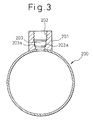
- Fig. 3 is a cross-sectional view of a portion where the exhaust gas temperature sensor is mounted.
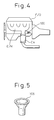
- Fig. 4 is a typical diagram showing a state in which the exhaust gas temperature sensor 100 is mounted on a vehicle, and the exhaust gas temperature sensor 100 is mounted in the vicinity of a location where exhaust tubes of an exhaust manifold E/M of the engine (heat engine) E/G are collected.
- Reference character Ca denotes a three-way catalytic converter for purifying exhaust gases by promoting the oxidation-reduction reaction of exhaust gases.
- reference numeral 101 denotes a sensor main body such as a thermistor which is exposed to exhaust gases flowing within the exhaust pipe 200 for sensing the temperature of exhaust gas
- reference numeral 102 denotes a sheath pin core wire electrically connected to the sensor main body 101.
- Reference numeral 103 denotes a sensor cover for covering the sensor main body 101
- reference numeral 104 denotes a cylindrical sheath pin for covering the sheath pin core wire 102.
- the exhaust temperature sensor 100 is constituted by the sensor main body 101, the sheath pin core wire 102 and the sheath pin 104.
- reference numeral 201 denotes a boss portion (a mounting seat) welded to the exhaust pipe 200 for mounting the exhaust gas temperature sensor 100, and a through hole 203 penetrating to the interior of the exhaust pipe 200 is formed in the boss portion 201 by making use of a prepared hole formed in the boss portion 201 when forming an internal thread portion 202.
- a rib (a sealing member) 105 is joined to the sheath pin 104 of the exhaust gas sensor 100 by brazing or welding, and formed on the rib 105 is a conical tapered surface 105a adapted to be brought into contact with a tapered portion 203a (refer to Fig. 3) of the through hole (prepared hole) 203, as shown in Fig. 1, for preventing exhaust gas from leaking from the through hole 203, into which the exhaust gas temperature sensor 100 is inserted, to the outside.
- reference numeral 106 denotes a nipple nut (a fixing member) having formed thereon an external thread portion 106a for threaded connection to the internal thread portion 202 of the boss portion 201, and formed in this nipple nut 106 is an insertion hole 106b into which a cylindrical protection tube 107 for covering the sheath pin 104 is inserted.
- protection tube 107 is joined to the rib 105 through brazing or welding, and the nipple nut 106 is allowed to slide in longitudinal directions relative to the protection tube 107.
- the nipple nut 106 is screwed (tightened) into the boss portion 201, so that the exhaust gas temperature sensor 100 is fixed to the boss portion 201 (the exhaust pipe 200) while pressing the tapered portion 105a against the tapered portion 203a by virtue of fastening force (clamping force) generated while the nipple nut 106 is so screwed into the boss portion 201.
- the coefficients ⁇ of linear thermal expansion of the rib 105, the nipple nut 106 and the boss portion 201 are made substantially the same so that the thermal deformations (thermal expansions and contractions) of the rib 105, the nipple nut 106 and the boss portion 201 become substantially the same.
- the protection tube 107 is also formed of SUS 304.
- reference numeral 108 denotes a connector for electrically connecting a lead wire 109 with the sheath pin core wire 102
- reference numeral 110 denotes a rubber or resin bush for holding and fixing the lead wire 109.
- This bush 110 is fixed in the protection tube 107 by plastically deforming (caulking) the protection tube 107 in such a manner as to reduce the inside diameter of thereof.
- reference numeral 111 denotes an insulation tube made from tetrafluoroethylene (Teflon: Trade mark) for preventing the connector 108 from coming into contact with the protection tube 107.
- Teflon tetrafluoroethylene
- the rib 105, the nipple nut 106 and the boss portion 201 are constructed so that the thermal deformations (thermal expansions and contractions) thereof become substantially the same by making the coefficients ⁇ of linear thermal expansion of the rib 105, the nipple nut 106 and the boss portion 201 substantially the same, even if the thermal deformations (thermal expansions and contractions) are made larger than those of the conventional means, the rib 105, the nipple nut 106 and the boss portion 201 are thermally expanded and/or contracted substantially all together. Consequently, the loosening of threads due to a hot-cold cycle can be prevented.
- the rib 105, the nipple nut 106 and the boss portion 201 are formed of stainless steel which is a metal having superior anti-oxidization properties, the corrosion thereof can be prevented to thereby improve the reliability (durability) of the temperature sensor 100.
- the rib 105, the nipple nut 106 and the boss portion 201 are constructed so that the thermal deformations (thermal expansions and contractions) thereof become substantially the same by making the coefficients ⁇ of linear thermal expansion of the rib 105, the nipple nut 106 and the boss portion 203 substantially the same, it is desirable that the difference in coefficients of linear thermal expansion (a difference between the maximum coefficient of linear thermal expansion and the minimum coefficient of linear thermal expansion) is 2 ⁇ 10 -6 /°C or less.
- the boss portion 201 is formed of austenite stainless steel in the first embodiment
- the rib 105, the nipple nut 106 and the boss portion 201 are formed of ferrite stainless steel.
- the boss portion 201 is formed of SUS 430 (American Iron and Steel Institute AISI 430) to JIS, the rib 105 from SUS 430 and the nipple nut 106 from SUS 430.
- the rib 105, the nipple nut 106 and the boss portion 201 are formed of martensite stainless steel.
- the rib 105, the nipple nut 106 and the boss portion 201 are formed of SUS 410 (AISI 410) to JIS.
- the coefficient ⁇ of linear thermal expansion is the coefficient of expansion of a material relative to change in unit temperature, even if the coefficients of linear thermal expansion are equal, the sizes of the rib 105, the nipple nut 106 and the boss portion 201 are largely different, there may occur a case in which the thermal deformations (thermal expansions and contractions) do not become substantially the same due to the temperature distributions of the materials. In addition, there may be a case in which selecting materials having substantially the same coefficients of linear thermal expansion is difficult.
- the size of the rib 105 is reduced so as to reduce the thermal deformation (thermal expansion and contraction) of the rib 105, so that the deformations (thermal expansions and contractions) of the rib 105, the nipple nut 106 and the boss portion 201 become substantially the same.
- a pipe material is flared (pressed) so as to form the rib 105.
- the size of the rib 105 is reduced so as to reduce the thermal deformation (thermal expansion and contraction) of the rib 105, so that the deformations (thermal expansions and contractions) of the rib 105, the nipple nut 106 and the boss portion 201 become substantially the same
- the size of at least one of the rib 105, the nipple nut 106 and the boss portion 201 is adjusted, so that the deformations (thermal expansions and contractions) of the rib 105, the nipple nut 106 and the boss portion 201 become substantially the same.
- the embodiment is not limited to this, and for example, the size of the rib 105 may be increased.
- the temperature of the sensor 100 reaches 500 to 700 degrees °C. Due to this, since heat is conducted to the bush 110 via the protection tube 107, there occurs a case where the temperature of the bush 110 exceeds the heat resistant limit temperature (about 200 degrees °C) of the bush 110 (rubber or resin).
- the fixing position of the bush 110 is separated as far away from the rib 105 as possible by extending the length of the protection tube 107, but when the protection tube 107 is extended, the sheath pin 104 also has to be extended, and therefore the sheath pin 104 may resonate as the vehicle vibrates (vibrations of the engine), leading to a risk of the sheath pin 104 failing due to fatigue.
- the resonance of the sheath pin 104 is prevented by providing a bracket (a spacer ring) 107a for fixing the sheath pin 104 to the protection tube 107 and the length of the protection tube 107 is extended so that the fixing position of the bush 110 is separated as far away from the rib 105 as possible.
- the reliability (durability) of the exhaust gas temperature sensor 100 can be improved.
- Fig. 6A shows a construction in which a stepped block-like bracket 107a is jointed to the sheath pin 104 and the protection tube 107 through caulking or welding (brazing)
- Fig. 6B shows a construction in which a cylindrical block-like bracket 107a is joined to the sheath pin 104 and the protection tube 107 through caulking
- Fig. 6C shows a construction in which an umbrella-like bracket 107a is joined to the sheath pin 104 and the protection tube 107 through caulking or welding (brazing).
- bracket 107a While only a single bracket 107a is used in this embodiment, a plurality of brackets 107a may be provided and, if this occurs, it is desirable that the brackets are provided at intervals of about 25mm.
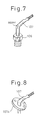
- the interference of the protection tube 107 with the equipment mounted in the vicinity of the exhaust gas temperature sensor 100 can be prevented by bending, in advance, the protection tube 107, as shown in Fig. 7 and, moreover, a mark indicating a mounting direction may be applied to the protection tube 107 so to prevent the occurrence of an error in assembling the exhaust gas temperature sensor 100.
- the protection tube 107 is extended as a flexible tube having a certain flexibility, as shown in Fig. 9, and a bracket 107a is provided for fixing the sheath pin 104 to the protection tube 107.
- the present invention has been described as being applied to the mounting structure for the exhaust gas temperature sensor in the embodiments, the present invention is not limited thereto, but may be applied to mounting structures for other temperature sensors.
- the present invention is not limited thereto, and those constituent members may be formed from other metals or other materials (such as ceramics).
- the external thread portion may be provided on the boss portion 201 and the internal thread portion may be provided on the nipple nut 106.
- the thermal deformations (thermal expansions and contractions) of a rib 105, a nipple nut 106 and a boss portion 201 are made substantially the same by making the coefficients of linear thermal expansion thereof substantially the same. According to the construction, even if an exhaust gas temperature sensor 100 is disposed in the vicinity of an exhaust manifold whereby the thermal deformations (thermal expansions and contractions) of the rib 105, the nipple nut 106 and the boss portion 201 are large, since the rib 105, the nipple nut 106 and the boss portion 201 are thermally expanded and/or contracted substantially all together, the loosening of threads due to a hot-cold cycle can be prevented.
Landscapes
- Physics & Mathematics (AREA)
- General Physics & Mathematics (AREA)
- Exhaust Silencers (AREA)
- Measuring Temperature Or Quantity Of Heat (AREA)
Abstract
Description
- The present invention relates to a mounting structure, for a temperature sensor for detecting the temperature of fluid flowing through a tube, and the mounting structure according to the present invention is effective when applied to a mounting structure for an exhaust gas temperature sensor for detecting the temperature of exhaust gas discharged from a heat engine such as an internal combustion engine.
- Fig. 2A is a typical diagram showing the mounting structure of a temperature sensor (an exhaust gas temperature sensor) 100, and Fig. 2B is an enlarged view of a portion A in Fig. 2A. The
temperature sensor 100 is fixedly threaded to aboss portion 201 welded to anexhaust pipe 200. - Here, in Fig. 2A,
reference numeral 103 denotes a cover for protecting a sensor main body such as a thermistor, andreference numeral 104 denotes a sheath pin for protecting a sheath pin core wire which is electrically joined to the sensor main body. In addition,reference numeral 105 denotes a rib adapted to be brought into contact with theboss portion 201 for preventing exhaust gas from leaking from a portion where thetemperature sensor 100 is mounted to the outside, and thisrib 105 is joined to thesheath pin 104. - Then, a
nipple nut 106 having external threads formed thereon is thread fastened to an internal thread portion of theboss portion 201, so that therib 105 is pressed against theboss portion 201, whereby therib 105 and theboss portion 201 are tightly secured to each other, and thetemperature sensor 100 is also fixedly mounted on the boss portion 201(the exhaust pipe 200). - In this construction, conventionally, the
nipple nut 106 is formed of a material having a coefficient α of linear thermal expansion which is larger than that of theboss portion 201 so that the fastening force (the clamping force) between thenipple nut 106 and theboss portion 201 is prevented from decreasing by virtue of thermal expansion of thenipple nut 106. - Incidentally, in recent years, as shown in Fig. 4, a means has been adopted in which a catalytic converter Ca is provided closer to an exhaust side of an engine E/G so as to activate the catalytic converter Ca at an earlier stage to thereby enhance the exhaust gas purifying efficiency of the catalytic converter Ca and, in this means, the exhaust
gas temperature sensor 100 needs to be mounted in the vicinity of the exhaust side of the engine. - Conventionally, the exhaust gas temperature sensor is mounted in the
boss portion 201 which is heated up to in the order of 400 degrees °C. Due to the adoption of the close coupled catalytic converter, however, in recent years, the exhaust gas temperature sensor is mounted in theboss portion 201 which is heated to or to move than 600 degrees °C, and this makes the thermal deformations (thermal expansions and contractions) of theboss portion 201, therib 105 and thenipple nut 106 larger than those conventionally exhibited, and with the conventional means in which thenipple nut 106 is formed of the material having the coefficient α of linear thermal expansion which is larger than that of theboss portion 201, stress which is greater than the yield stress may be produced in at least one of theboss portion 201, therib 105 and thenipple nut 106, there thus being a possibility that any of theboss portion 201, therib 105 and thenipple nut 106 is plastically deformed. - Thus, in the event that any of the
boss portion 201, therib 105 and thenipple nut 106 is plastically deformed, it is impossible to prevent the lowering of the fastening force between thenipple nut 106 and theboss portion 201, and this may lead to a risk of causing a problem that the nipple nut 106 (at the threaded portion) becomes loose. Hereinafter, the problem is referred to as "loosening of threads due to a hot-cold cycle". - The present invention was made in view of the aforesaid drawbacks and an object thereof is to prevent the loosening of threads due to a hot-cold cycle.
- With a view to attaining the object, according to an aspect of the present invention, there is provided a mounting structure for a temperature sensor (100) for detecting the temperature of fluid flowing within a tube (200), the mounting structure having a mounting seat (201) provided on the tube (200) and having a thread portion (202) formed therein for mounting the temperature sensor (100), a sealing member (105) joined to the temperature sensor (100) and adapted to be brought into contact with the mounting seat (201) to thereby prevent fluid from leaking from a portion, where the temperature sensor (100) is inserted, to the outside and a fixing member (106) adapted to be brought into thread connection with the thread portion (202) in such a manner as to press the sealing member (105) against the mounting seat (201), whereby the mounting seat (201), the sealing member (105) and the fixing member (106) are constructed such that the thermal deformations thereof become substantially the same.
- According to this construction, even if the thermal deformations (thermal expansions and contractions) are larger than those of the conventional structure, since the mounting seat (201), the sealing member (105) and the fixing member (106) are thermally expanded or contracted substantially all together, the loosening of threads due to a hot-cold cycle can be prevented.
- According to another aspect of the present invention, there is provided a mounting structure for a temperature sensor as set forth in the aforesaid aspect of the present invention, wherein, the temperature sensor (100) has a sensor portion (101) for sensing temperature, a sheath pin core wire (102) electrically connected to the sensor portion (101) and a cylindrical sheath pin (104) for covering the sheath pin core wire (102), wherein the sealing member (105) is joined to the sheath pin (104), wherein the sheath pin (104) is covered with a cylindrical protection tube (107), wherein a rubber bush (110) is fixed to the protection tube (108) for holding and fixing a lead wire (109) electrically connected to the sheath pin core wire (102), and wherein the sheath pin (104) is fixed to the protection tube (107).
- According to the construction, because resonance of the sheath pin (104) can be prevented, the protection tube (107) can be made longer.
- Consequently, because the fixing position of the bush (110) can be kept as far away from the tube (200) as possible, the bush (110) is prevented from being heated, by heat conducted to the bush (110) via the protection tube (107), to a temperature exceeding the maximum temperature of the bush (110) over which the heat resistance of the bush (110) is deteriorated, whereby the reliability (durability) of the temperature sensor (100) can be improved.
- Reference numerals in parentheses imparted to the aforesaid means are examples intended to denote corresponding relationships with specific means described in the description of the preferred embodiments of the present invention, which follow.
- The present invention will be more fully understood with reference to the accompanying drawings and the preferred embodiments of the invention.
- In the drawings:
- Fig. 1 is a cross-sectional view of an exhaust gas temperature sensor (a temperature sensor) for use in a temperature sensor mounting structure according to a first embodiment of the present invention;
- Fig. 2A is a typical diagram showing a temperature sensor mounting structure according to the first embodiment of the present invention, Fig 2B being an enlarged view of a portion A in Fig. 2A;
- Fig. 3 is a cross-sectional view of an exhaust pipe for use in the temperature mounting structure according to the first embodiment of the present invention;
- Fig. 4 is a typical diagram of an engine exhaust system to which the temperature mounting structure according to the first embodiment of the present invention is applied;
- Fig. 5 is a perspective view of a rib for use in a temperature sensor mounting structure according to a fourth embodiment of the present invention;
- Figs. 6A to 6C are cross-sectional views of a protection tube for an exhaust gas temperature sensor for use in a temperature sensor mounting structure according to a fifth embodiment of the present invention;
- Fig. 7 is a perspective view of an exhaust gas temperature sensor for use in a temperature sensor mounting structure according to a sixth embodiment of the present invention;
- Fig. 8 is a perspective view of an exhaust gas temperature sensor for use in a temperature sensor mounting structure according to a seventh embodiment of the present invention; and
- Fig. 9 is a perspective view of an exhaust gas temperature sensor for use in a temperature sensor mounting structure according to an eighth embodiment of the present invention.
-
- In this embodiment, a temperature sensor mounting structure according to the present invention is applied to a mounting structure of an exhaust
gas temperature sensor 100 for detecting the temperature of exhaust gases discharged from an automotive engine (an internal combustion engine). Fig. 1 is a typical diagram of the exhaustgas temperature sensor 100, Fig. 2A is a typical diagram showing a state in which the exhaustgas temperature sensor 100 is mounted in anexhaust pipe 200, and Fig. 3 is a cross-sectional view of a portion where the exhaust gas temperature sensor is mounted. - In addition, Fig. 4 is a typical diagram showing a state in which the exhaust
gas temperature sensor 100 is mounted on a vehicle, and the exhaustgas temperature sensor 100 is mounted in the vicinity of a location where exhaust tubes of an exhaust manifold E/M of the engine (heat engine) E/G are collected. Reference character Ca denotes a three-way catalytic converter for purifying exhaust gases by promoting the oxidation-reduction reaction of exhaust gases. - In Fig. 1,
reference numeral 101 denotes a sensor main body such as a thermistor which is exposed to exhaust gases flowing within theexhaust pipe 200 for sensing the temperature of exhaust gas, andreference numeral 102 denotes a sheath pin core wire electrically connected to the sensormain body 101. -
Reference numeral 103 denotes a sensor cover for covering the sensormain body 101, andreference numeral 104 denotes a cylindrical sheath pin for covering the sheathpin core wire 102. Theexhaust temperature sensor 100 is constituted by the sensormain body 101, the sheathpin core wire 102 and thesheath pin 104. - In Figs. 2A and 3,
reference numeral 201 denotes a boss portion (a mounting seat) welded to theexhaust pipe 200 for mounting the exhaustgas temperature sensor 100, and athrough hole 203 penetrating to the interior of theexhaust pipe 200 is formed in theboss portion 201 by making use of a prepared hole formed in theboss portion 201 when forming aninternal thread portion 202. - On the other hand, a rib (a sealing member) 105 is joined to the
sheath pin 104 of theexhaust gas sensor 100 by brazing or welding, and formed on therib 105 is a conicaltapered surface 105a adapted to be brought into contact with a tapered portion 203a (refer to Fig. 3) of the through hole (prepared hole) 203, as shown in Fig. 1, for preventing exhaust gas from leaking from the throughhole 203, into which the exhaustgas temperature sensor 100 is inserted, to the outside. - In addition,
reference numeral 106 denotes a nipple nut (a fixing member) having formed thereon an external thread portion 106a for threaded connection to theinternal thread portion 202 of theboss portion 201, and formed in thisnipple nut 106 is aninsertion hole 106b into which acylindrical protection tube 107 for covering thesheath pin 104 is inserted. - In addition, the
protection tube 107 is joined to therib 105 through brazing or welding, and thenipple nut 106 is allowed to slide in longitudinal directions relative to theprotection tube 107. - Then, in mounting the exhaust
gas temperature sensor 100 in the boss portion 201 (the exhaust pipe 200), with thetapered portion 105a of therib 105 being in contact with the tapered portion 203a of the through hole (prepared hole) 203, thenipple nut 106 is screwed (tightened) into theboss portion 201, so that the exhaustgas temperature sensor 100 is fixed to the boss portion 201 (the exhaust pipe 200) while pressing thetapered portion 105a against the tapered portion 203a by virtue of fastening force (clamping force) generated while thenipple nut 106 is so screwed into theboss portion 201. - In addition, in this embodiment, the coefficients α of linear thermal expansion of the
rib 105, thenipple nut 106 and theboss portion 201 are made substantially the same so that the thermal deformations (thermal expansions and contractions) of therib 105, thenipple nut 106 and theboss portion 201 become substantially the same. - To be specific, the
boss portion 201 and therib 105 are formed of SUS304 (American Iron and Steel Institute AISI 304) to Japanese Industrial Standards (JIS) (α=18.9×10⁻⁶/°C) and thenipple nut 106 is formed of SUSXM7 (American Society for Testing and Material ASTM XM7) to JIS (α=18.7×10⁻⁶/°C). Incidentally, in this embodiment, theprotection tube 107 is also formed of SUS 304. - In addition, in Fig. 1,
reference numeral 108 denotes a connector for electrically connecting alead wire 109 with the sheathpin core wire 102, andreference numeral 110 denotes a rubber or resin bush for holding and fixing thelead wire 109. Thisbush 110 is fixed in theprotection tube 107 by plastically deforming (caulking) theprotection tube 107 in such a manner as to reduce the inside diameter of thereof. - In addition,
reference numeral 111 denotes an insulation tube made from tetrafluoroethylene (Teflon: Trade mark) for preventing theconnector 108 from coming into contact with theprotection tube 107. - Next, features of the embodiment will be described.
- According to this embodiment, since the
rib 105, thenipple nut 106 and theboss portion 201 are constructed so that the thermal deformations (thermal expansions and contractions) thereof become substantially the same by making the coefficients α of linear thermal expansion of therib 105, thenipple nut 106 and theboss portion 201 substantially the same, even if the thermal deformations (thermal expansions and contractions) are made larger than those of the conventional means, therib 105, thenipple nut 106 and theboss portion 201 are thermally expanded and/or contracted substantially all together. Consequently, the loosening of threads due to a hot-cold cycle can be prevented. - In addition, since the
rib 105, thenipple nut 106 and theboss portion 201 are formed of stainless steel which is a metal having superior anti-oxidization properties, the corrosion thereof can be prevented to thereby improve the reliability (durability) of thetemperature sensor 100. - Additionally, in this embodiment, since the
rib 105, thenipple nut 106 and theboss portion 201 are constructed so that the thermal deformations (thermal expansions and contractions) thereof become substantially the same by making the coefficients α of linear thermal expansion of therib 105, thenipple nut 106 and theboss portion 203 substantially the same, it is desirable that the difference in coefficients of linear thermal expansion (a difference between the maximum coefficient of linear thermal expansion and the minimum coefficient of linear thermal expansion) is 2×10⁻⁶/°C or less. - While the
rib 105, thenipple nut 106 and theboss portion 201 are formed of austenite stainless steel in the first embodiment, in this second embodiment, therib 105, thenipple nut 106 and theboss portion 201 are formed of ferrite stainless steel. To be specific, theboss portion 201 is formed of SUS 430 (American Iron and Steel Institute AISI 430) to JIS, therib 105 from SUS 430 and thenipple nut 106 from SUS 430. - In this embodiment, the
rib 105, thenipple nut 106 and theboss portion 201 are formed of martensite stainless steel. To be specific, therib 105, thenipple nut 106 and theboss portion 201 are formed of SUS 410 (AISI 410) to JIS. - Since the coefficient α of linear thermal expansion is the coefficient of expansion of a material relative to change in unit temperature, even if the coefficients of linear thermal expansion are equal, the sizes of the
rib 105, thenipple nut 106 and theboss portion 201 are largely different, there may occur a case in which the thermal deformations (thermal expansions and contractions) do not become substantially the same due to the temperature distributions of the materials. In addition, there may be a case in which selecting materials having substantially the same coefficients of linear thermal expansion is difficult. - To cope with the drawbacks, in this embodiment, as shown in Fig. 5, the size of the
rib 105 is reduced so as to reduce the thermal deformation (thermal expansion and contraction) of therib 105, so that the deformations (thermal expansions and contractions) of therib 105, thenipple nut 106 and theboss portion 201 become substantially the same. - In this embodiment, a pipe material is flared (pressed) so as to form the
rib 105. - In addition, in this embodiment, while the size of the
rib 105 is reduced so as to reduce the thermal deformation (thermal expansion and contraction) of therib 105, so that the deformations (thermal expansions and contractions) of therib 105, thenipple nut 106 and theboss portion 201 become substantially the same, in this embodiment, the size of at least one of therib 105, thenipple nut 106 and theboss portion 201 is adjusted, so that the deformations (thermal expansions and contractions) of therib 105, thenipple nut 106 and theboss portion 201 become substantially the same. However, the embodiment is not limited to this, and for example, the size of therib 105 may be increased. - Since the exhaust
gas temperature sensor 100 is mounted in the vicinity of the location where the exhaust tubes of the exhaust manifold E/M are collected, the temperature of the sensor reaches 500 to 700 degrees °C. Due to this, since heat is conducted to thebush 110 via theprotection tube 107, there occurs a case where the temperature of thebush 110 exceeds the heat resistant limit temperature (about 200 degrees °C) of the bush 110 (rubber or resin). - To cope with this problem, the fixing position of the
bush 110 is separated as far away from therib 105 as possible by extending the length of theprotection tube 107, but when theprotection tube 107 is extended, thesheath pin 104 also has to be extended, and therefore thesheath pin 104 may resonate as the vehicle vibrates (vibrations of the engine), leading to a risk of thesheath pin 104 failing due to fatigue. - To cope with this problem, in this embodiment, as shown in Figs. 6A to 6C, the resonance of the
sheath pin 104 is prevented by providing a bracket (a spacer ring) 107a for fixing thesheath pin 104 to theprotection tube 107 and the length of theprotection tube 107 is extended so that the fixing position of thebush 110 is separated as far away from therib 105 as possible. - Consequently, since the
bush 110 is prevented from being heated by heat conducted thereto via theprotection tube 107 so that the temperature of thebush 110 does not exceed the heat resistant limit temperature thereof, the reliability (durability) of the exhaustgas temperature sensor 100 can be improved. - In addition, Fig. 6A shows a construction in which a stepped block-
like bracket 107a is jointed to thesheath pin 104 and theprotection tube 107 through caulking or welding (brazing), Fig. 6B shows a construction in which a cylindrical block-like bracket 107a is joined to thesheath pin 104 and theprotection tube 107 through caulking, and Fig. 6C shows a construction in which an umbrella-like bracket 107a is joined to thesheath pin 104 and theprotection tube 107 through caulking or welding (brazing). - While only a
single bracket 107a is used in this embodiment, a plurality ofbrackets 107a may be provided and, if this occurs, it is desirable that the brackets are provided at intervals of about 25mm. - By the way, when the
protection tube 107 is extended, there is a risk that theprotection tube 107 may interfere with equipment mounted in the vicinity of the exhaustgas temperature sensor 100. - To cope with this problem, in this embodiment, the interference of the
protection tube 107 with the equipment mounted in the vicinity of the exhaustgas temperature sensor 100 can be prevented by bending, in advance, theprotection tube 107, as shown in Fig. 7 and, moreover, a mark indicating a mounting direction may be applied to theprotection tube 107 so to prevent the occurrence of an error in assembling the exhaustgas temperature sensor 100. - In this embodiment, the
protection tube 107 is extended as a flexible tube having a certain flexibility, as shown in Fig. 9, and abracket 107a is provided for fixing thesheath pin 104 to theprotection tube 107. - While the present invention has been described as being applied to the mounting structure for the exhaust gas temperature sensor in the embodiments, the present invention is not limited thereto, but may be applied to mounting structures for other temperature sensors.
- In addition, in the above embodiments, while the
rib 105, thenipple nut 106 and theboss portion 201 are formed of metal of stainless steel system, the present invention is not limited thereto, and those constituent members may be formed from other metals or other materials (such as ceramics). - In addition, in the above embodiments, while the internal thread portion is provided on the
boss portion 201 and the external thread portion is provided on thenipple nut 106, contrary to this, the external thread portion may be provided on theboss portion 201 and the internal thread portion may be provided on thenipple nut 106. - The thermal deformations (thermal expansions and contractions) of a
rib 105, anipple nut 106 and aboss portion 201 are made substantially the same by making the coefficients of linear thermal expansion thereof substantially the same. According to the construction, even if an exhaustgas temperature sensor 100 is disposed in the vicinity of an exhaust manifold whereby the thermal deformations (thermal expansions and contractions) of therib 105, thenipple nut 106 and theboss portion 201 are large, since therib 105, thenipple nut 106 and theboss portion 201 are thermally expanded and/or contracted substantially all together, the loosening of threads due to a hot-cold cycle can be prevented.
Claims (10)
- A mounting structure, for a temperature sensor for detecting the temperature of fluid flowing within a tube, said mounting structure comprising a mounting seat provided on said tube and having a threaded portion formed therein for mounting said temperature sensor, a sealing member joined to said temperature sensor and adapted to be brought into contact with said mounting seat to thereby prevent fluid from leaking from a portion, where said temperature sensor is inserted, to the outside and a fixing member adapted to be brought into threaded connection with said threaded portion in such a manner as to press said sealing member against said mounting seat, whereby said mounting seat, said sealing member and said fixing member are constructed such that the thermal deformations thereof become substantially the same.
- A mounting structure for a temperature sensor according to Claim 1, wherein said mounting seat, said sealing member and said fixing member are constructed such that the thermal deformations thereof become substantially the same by making the coefficients of linear thermal expansion of said mounting seats, said sealing member and said fixing member substantially the same.
- A mounting structure for a temperature sensor according to Claim 2, wherein the fluid flowing within said tube is exhaust gases discharged from a heat engine, and wherein
Said mounting seat, said sealing member and said fixing member are formed of metal. - A mounting structure for a temperature sensor according to Claim 3, wherein said metal is a metal having anti-oxidization properties.
- A mounting structure for a temperature sensor according to Claim 2, wherein the difference in coefficients of linear thermal expansion of said mounting seat, said sealing member and said fixing member is 2×10⁻⁶/°C or less.
- A mounting structure for a temperature sensor according to Claim 3, wherein said mounting seat, said sealing member and said fixing member are exposed to an atmosphere at a temperature of 500 to 700 degrees °C.
- A mounting structure for a temperature sensor according to Claim 1, wherein fluid flowing within said tube is exhaust gases discharged from a heat engine, and wherein
said mounting seat and said sealing member are formed of SUS 304 (AISI 304) to JIS and said fixing member is formed of SUS XM 7 (ASTM XM7) to JIS. - A mounting structure for a temperature sensor according to Claim 1, wherein fluid flowing within said tube is exhaust gases discharged from a heat engine, and wherein
said mounting seat is formed of SUS430, said sealing member is formed of SUS 430 (AISI 430) of JIS and said fixing member is formed of SUS 430. - A mounting structure for a temperature sensor according to Claim 1, wherein fluid flowing within said tube is exhaust gases discharged from a heat engine, and wherein
said mounting seat, said sealing member and said fixing member are formed of SUS 410 (AISI 410) to JIS. - A mounting structure for a temperature sensor according to Claim 1, wherein said temperature sensor has a sensor portion for sensing temperature, a sheath pin core wire electrically connected to said sensor portion and a cylindrical sheath pin for covering said sheath pin core wire, whereinsaid sealing member is joined to said sheath pin, whereinsaid sheath pin is covered with a cylindrical protection tube, whereina rubber bush is fixed to said protection tube for holding and fixing a lead wire electrically connected to said sheath pin core wire, and whereinsaid sheath pin is fixed to said protection tube.
Applications Claiming Priority (4)
| Application Number | Priority Date | Filing Date | Title |
|---|---|---|---|
| JP2000244613 | 2000-08-11 | ||
| JP2000244613 | 2000-08-11 | ||
| JP2001199121A JP2002122486A (en) | 2000-08-11 | 2001-06-29 | Mounting structure of temperature sensor |
| JP2001199121 | 2001-06-29 |
Publications (2)
| Publication Number | Publication Date |
|---|---|
| EP1180670A1 true EP1180670A1 (en) | 2002-02-20 |
| EP1180670B1 EP1180670B1 (en) | 2010-04-14 |
Family
ID=26597855
Family Applications (1)
| Application Number | Title | Priority Date | Filing Date |
|---|---|---|---|
| EP01119236A Expired - Lifetime EP1180670B1 (en) | 2000-08-11 | 2001-08-09 | Temperature sensor mounting structure |
Country Status (4)
| Country | Link |
|---|---|
| US (1) | US20020039378A1 (en) |
| EP (1) | EP1180670B1 (en) |
| JP (1) | JP2002122486A (en) |
| DE (1) | DE60141794D1 (en) |
Cited By (3)
| Publication number | Priority date | Publication date | Assignee | Title |
|---|---|---|---|---|
| CN102465750A (en) * | 2010-11-18 | 2012-05-23 | 铃木株式会社 | Mounting structure of component to exhaust pipe |
| DE102014208049B4 (en) * | 2013-04-30 | 2017-12-21 | Ngk Spark Plug Co., Ltd. | temperature sensor |
| CN108534914A (en) * | 2018-04-18 | 2018-09-14 | 北京方等传感器研究所有限公司 | Temperature sensor connection structure and connection system |
Families Citing this family (23)
| Publication number | Priority date | Publication date | Assignee | Title |
|---|---|---|---|---|
| JP4016627B2 (en) * | 2000-11-22 | 2007-12-05 | 株式会社デンソー | Temperature sensor |
| WO2003040673A2 (en) * | 2001-11-02 | 2003-05-15 | Phipps Jack M | Temperature sensor with enhanced ambient air temperature detection |
| US6997607B2 (en) * | 2002-11-22 | 2006-02-14 | Ngk Spark Plug Co., Ltd. | Temperature sensor |
| US7581879B2 (en) * | 2004-06-30 | 2009-09-01 | Ngk Spark Plug Co., Ltd. | Temperature sensor |
| JP4829007B2 (en) * | 2006-05-16 | 2011-11-30 | 日本特殊陶業株式会社 | Temperature sensor |
| US7665890B2 (en) * | 2006-06-22 | 2010-02-23 | Watlow Electric Manufacturing Company | Temperature sensor assembly and method of manufacturing thereof |
| JP2008215846A (en) * | 2007-02-28 | 2008-09-18 | Denso Corp | Temperature sensor mounting structure |
| JP4986692B2 (en) * | 2007-04-13 | 2012-07-25 | 日本特殊陶業株式会社 | Temperature sensor |
| JP5038091B2 (en) * | 2007-10-20 | 2012-10-03 | 日本特殊陶業株式会社 | Temperature sensor |
| JP5134701B2 (en) * | 2010-07-20 | 2013-01-30 | 日本特殊陶業株式会社 | Temperature sensor |
| JP5141791B2 (en) * | 2010-08-30 | 2013-02-13 | 株式会社デンソー | Temperature sensor |
| JP5854624B2 (en) * | 2011-04-19 | 2016-02-09 | 株式会社鷺宮製作所 | Temperature measuring device and temperature sensor |
| JP5763494B2 (en) | 2011-09-30 | 2015-08-12 | 日本特殊陶業株式会社 | Lubricating paint composition and mounting part for internal combustion engine |
| JP5451793B2 (en) * | 2012-02-10 | 2014-03-26 | 東京エレクトロン株式会社 | Temperature sensor and heat treatment apparatus |
| JP2015232552A (en) * | 2014-05-12 | 2015-12-24 | 日本特殊陶業株式会社 | Sensor and manufacturing method thereof |
| US10161639B2 (en) * | 2015-03-10 | 2018-12-25 | Joseph Copeland | Heat transfer apparatus and heat transfer system for masonry heater |
| JP6399024B2 (en) * | 2016-03-29 | 2018-10-03 | コベルコ建機株式会社 | Vehicle exhaust system |
| US10859445B2 (en) * | 2017-07-17 | 2020-12-08 | William L. Smith | Temperature sensor assembly |
| CN108303560A (en) * | 2018-04-18 | 2018-07-20 | 北京方等传感器研究所有限公司 | Anti-channeling structure and sensor |
| CN112067150B (en) * | 2020-09-03 | 2022-03-25 | 浙江赛威科光电科技有限公司 | Mounting structure and mounting method of low-temperature sensor |
| CN114018426B (en) * | 2021-11-28 | 2025-01-07 | 董大辽 | A thermal resistance temperature measuring instrument |
| DE102023111921B4 (en) * | 2023-05-08 | 2025-03-13 | Temperaturmeßtechnik Geraberg GmbH | Temperature sensor |
| CN119394456B (en) * | 2024-10-09 | 2025-08-26 | 江苏柯瑞机电工程股份有限公司 | A cooling tower outlet water temperature measuring device that prevents loosening |
Citations (4)
| Publication number | Priority date | Publication date | Assignee | Title |
|---|---|---|---|---|
| DE4021997A1 (en) | 1989-07-11 | 1991-01-17 | Nippon Denso Co | High temp. thermistor - made of chromium, titanium, manganese and silicon oxide(s) |
| JPH04276530A (en) | 1991-03-04 | 1992-10-01 | Matsushita Electric Ind Co Ltd | Temperature sensor |
| JPH09126910A (en) * | 1995-11-06 | 1997-05-16 | Matsushita Electric Ind Co Ltd | Temperature detector |
| DE10034265A1 (en) * | 1999-08-17 | 2001-02-22 | Denso Corp | Temperature sensor e.g. for exhaust gas system of motor vehicle has temperature-detecting element held in lid attached to outer tube via connecting part of smaller diameter |
Family Cites Families (9)
| Publication number | Priority date | Publication date | Assignee | Title |
|---|---|---|---|---|
| US5707152A (en) * | 1986-01-15 | 1998-01-13 | Krywitsky; Lee A. | Method for using reusable pipe union and pipe cap assembly for wide thermal cycling |
| DE69111493T2 (en) * | 1990-03-12 | 1996-03-21 | Ngk Insulators Ltd | Wafer heaters for apparatus, for semiconductor manufacturing heating system with these heaters and manufacture of heaters. |
| JPH057947U (en) * | 1991-07-09 | 1993-02-02 | ダイハツ工業株式会社 | Exhaust system mounting sensor mounting device |
| JPH08110267A (en) * | 1994-10-12 | 1996-04-30 | Nippondenso Co Ltd | Temperature sensor |
| JP3555492B2 (en) * | 1998-09-22 | 2004-08-18 | 株式会社デンソー | Temperature sensor |
| US6305841B1 (en) * | 1998-09-29 | 2001-10-23 | Denso Corporation | Temperature sensor with thermistor housed in blocked space having ventilation |
| JP2002267547A (en) * | 2001-03-14 | 2002-09-18 | Denso Corp | Temperature sensor |
| JP3788363B2 (en) * | 2001-03-23 | 2006-06-21 | 株式会社デンソー | Temperature sensor |
| US6599012B2 (en) * | 2002-01-03 | 2003-07-29 | Mamac Systems, Inc. | Thermowell adapter |
-
2001
- 2001-06-29 JP JP2001199121A patent/JP2002122486A/en active Pending
- 2001-08-03 US US09/920,839 patent/US20020039378A1/en not_active Abandoned
- 2001-08-09 EP EP01119236A patent/EP1180670B1/en not_active Expired - Lifetime
- 2001-08-09 DE DE60141794T patent/DE60141794D1/en not_active Expired - Lifetime
Patent Citations (4)
| Publication number | Priority date | Publication date | Assignee | Title |
|---|---|---|---|---|
| DE4021997A1 (en) | 1989-07-11 | 1991-01-17 | Nippon Denso Co | High temp. thermistor - made of chromium, titanium, manganese and silicon oxide(s) |
| JPH04276530A (en) | 1991-03-04 | 1992-10-01 | Matsushita Electric Ind Co Ltd | Temperature sensor |
| JPH09126910A (en) * | 1995-11-06 | 1997-05-16 | Matsushita Electric Ind Co Ltd | Temperature detector |
| DE10034265A1 (en) * | 1999-08-17 | 2001-02-22 | Denso Corp | Temperature sensor e.g. for exhaust gas system of motor vehicle has temperature-detecting element held in lid attached to outer tube via connecting part of smaller diameter |
Non-Patent Citations (2)
| Title |
|---|
| PATENT ABSTRACTS OF JAPAN vol. 017, no. 070 (P - 1485) 12 February 1993 (1993-02-12) * |
| PATENT ABSTRACTS OF JAPAN vol. 1997, no. 09 30 September 1997 (1997-09-30) * |
Cited By (6)
| Publication number | Priority date | Publication date | Assignee | Title |
|---|---|---|---|---|
| CN102465750A (en) * | 2010-11-18 | 2012-05-23 | 铃木株式会社 | Mounting structure of component to exhaust pipe |
| US8752866B2 (en) | 2010-11-18 | 2014-06-17 | Suzuki Motor Corporation | Mounting structure of component to exhaust pipe |
| CN102465750B (en) * | 2010-11-18 | 2015-09-30 | 铃木株式会社 | To the mounting structure of the parts that outlet pipe is installed |
| DE102014208049B4 (en) * | 2013-04-30 | 2017-12-21 | Ngk Spark Plug Co., Ltd. | temperature sensor |
| CN108534914A (en) * | 2018-04-18 | 2018-09-14 | 北京方等传感器研究所有限公司 | Temperature sensor connection structure and connection system |
| CN108534914B (en) * | 2018-04-18 | 2023-09-22 | 北京方等传感器研究所有限公司 | Temperature sensor connection structure and connection system |
Also Published As
| Publication number | Publication date |
|---|---|
| US20020039378A1 (en) | 2002-04-04 |
| DE60141794D1 (en) | 2010-05-27 |
| JP2002122486A (en) | 2002-04-26 |
| EP1180670B1 (en) | 2010-04-14 |
Similar Documents
| Publication | Publication Date | Title |
|---|---|---|
| EP1180670B1 (en) | Temperature sensor mounting structure | |
| US6698922B2 (en) | Temperature sensor | |
| US6240969B1 (en) | Conduit element for exhaust gas conduits of motor vehicles | |
| KR101244724B1 (en) | Exhaust gas purifying device | |
| US6360782B1 (en) | Exhaust pipe assembly of two-passage construction | |
| WO2010056411A1 (en) | Glow plug with metallic heater probe | |
| US6962346B2 (en) | Gasket and heat shield assembly for a flanged joint | |
| KR20180071966A (en) | High-temperature exhaust sensor | |
| JP7384854B2 (en) | Exhaust pipe | |
| US10697346B2 (en) | Flexible automotive exhaust tube system | |
| US6324837B1 (en) | Uncoupling element for uncoupling vibrations | |
| JP4861541B2 (en) | Decoupling hose for automobile engine exhaust pipe | |
| JPH11505313A (en) | Metallic expansion joints and vibration absorbers for pipe systems | |
| US7762063B2 (en) | Housing for an exhaust gas purification component for forming a joined connection with an exhaust line section, exhaust system having the housing and motor vehicle having the exhaust system | |
| US6811159B2 (en) | Gasket and heat shield for a flanged joint | |
| EP0860590B1 (en) | A flexible tube with a corrugated wall for uncoupling motor-vehicle exhaust pipes | |
| US7222516B2 (en) | Gas sensor, gas sensor cap, and gas sensor unit | |
| CN113242932B (en) | Pipes, exhaust gas sensors and sensor systems | |
| CN105308278B (en) | Minor structure is installed in casting for end cap module | |
| KR20180127225A (en) | Floating conductor housing | |
| US20020140232A1 (en) | Device for axially conneting two pipe-like components | |
| JP2000055851A (en) | Measuring sensor and method for forming a cable connection to the measuring sensor | |
| US6488313B1 (en) | Flexible connector assembly for exhaust system | |
| JP2004190610A (en) | Double piping joint structure | |
| JP2004100598A (en) | Exhaust gas purifying apparatus for engine and joint pipe for purifying exhaust gas having the same |
Legal Events
| Date | Code | Title | Description |
|---|---|---|---|
| PUAI | Public reference made under article 153(3) epc to a published international application that has entered the european phase |
Free format text: ORIGINAL CODE: 0009012 |
|
| AK | Designated contracting states |
Kind code of ref document: A1 Designated state(s): DE FR Kind code of ref document: A1 Designated state(s): AT BE CH CY DE DK ES FI FR GB GR IE IT LI LU MC NL PT SE TR |
|
| AX | Request for extension of the european patent |
Free format text: AL;LT;LV;MK;RO;SI |
|
| 17P | Request for examination filed |
Effective date: 20020215 |
|
| AKX | Designation fees paid |
Free format text: DE FR |
|
| 17Q | First examination report despatched |
Effective date: 20081106 |
|
| GRAP | Despatch of communication of intention to grant a patent |
Free format text: ORIGINAL CODE: EPIDOSNIGR1 |
|
| GRAS | Grant fee paid |
Free format text: ORIGINAL CODE: EPIDOSNIGR3 |
|
| GRAA | (expected) grant |
Free format text: ORIGINAL CODE: 0009210 |
|
| AK | Designated contracting states |
Kind code of ref document: B1 Designated state(s): DE FR |
|
| REF | Corresponds to: |
Ref document number: 60141794 Country of ref document: DE Date of ref document: 20100527 Kind code of ref document: P |
|
| PLBE | No opposition filed within time limit |
Free format text: ORIGINAL CODE: 0009261 |
|
| STAA | Information on the status of an ep patent application or granted ep patent |
Free format text: STATUS: NO OPPOSITION FILED WITHIN TIME LIMIT |
|
| 26N | No opposition filed |
Effective date: 20110117 |
|
| REG | Reference to a national code |
Ref country code: FR Ref legal event code: PLFP Year of fee payment: 15 |
|
| REG | Reference to a national code |
Ref country code: FR Ref legal event code: PLFP Year of fee payment: 16 |
|
| REG | Reference to a national code |
Ref country code: FR Ref legal event code: PLFP Year of fee payment: 17 |
|
| REG | Reference to a national code |
Ref country code: FR Ref legal event code: PLFP Year of fee payment: 18 |
|
| PGFP | Annual fee paid to national office [announced via postgrant information from national office to epo] |
Ref country code: DE Payment date: 20200819 Year of fee payment: 20 Ref country code: FR Payment date: 20200821 Year of fee payment: 20 |
|
| REG | Reference to a national code |
Ref country code: DE Ref legal event code: R071 Ref document number: 60141794 Country of ref document: DE |