EP1180666A1 - Structure for installing a fuel level sensor in a fuel tank for automobiles - Google Patents
Structure for installing a fuel level sensor in a fuel tank for automobiles Download PDFInfo
- Publication number
- EP1180666A1 EP1180666A1 EP01105615A EP01105615A EP1180666A1 EP 1180666 A1 EP1180666 A1 EP 1180666A1 EP 01105615 A EP01105615 A EP 01105615A EP 01105615 A EP01105615 A EP 01105615A EP 1180666 A1 EP1180666 A1 EP 1180666A1
- Authority
- EP
- European Patent Office
- Prior art keywords
- fuel
- level sensor
- fuel tank
- installing
- fuel level
- Prior art date
- Legal status (The legal status is an assumption and is not a legal conclusion. Google has not performed a legal analysis and makes no representation as to the accuracy of the status listed.)
- Withdrawn
Links
- 239000000446 fuel Substances 0.000 title claims abstract description 48
- 239000002828 fuel tank Substances 0.000 title claims abstract description 30
- 230000007257 malfunction Effects 0.000 abstract description 4
- 230000015556 catabolic process Effects 0.000 description 1
- 238000010586 diagram Methods 0.000 description 1
- 238000006073 displacement reaction Methods 0.000 description 1
- 239000012535 impurity Substances 0.000 description 1
- 230000001105 regulatory effect Effects 0.000 description 1
Images


Classifications
-
- B—PERFORMING OPERATIONS; TRANSPORTING
- B60—VEHICLES IN GENERAL
- B60K—ARRANGEMENT OR MOUNTING OF PROPULSION UNITS OR OF TRANSMISSIONS IN VEHICLES; ARRANGEMENT OR MOUNTING OF PLURAL DIVERSE PRIME-MOVERS IN VEHICLES; AUXILIARY DRIVES FOR VEHICLES; INSTRUMENTATION OR DASHBOARDS FOR VEHICLES; ARRANGEMENTS IN CONNECTION WITH COOLING, AIR INTAKE, GAS EXHAUST OR FUEL SUPPLY OF PROPULSION UNITS IN VEHICLES
- B60K15/00—Arrangement in connection with fuel supply of combustion engines or other fuel consuming energy converters, e.g. fuel cells; Mounting or construction of fuel tanks
- B60K15/03—Fuel tanks
- B60K15/077—Fuel tanks with means modifying or controlling distribution or motion of fuel, e.g. to prevent noise, surge, splash or fuel starvation
-
- G—PHYSICS
- G01—MEASURING; TESTING
- G01F—MEASURING VOLUME, VOLUME FLOW, MASS FLOW OR LIQUID LEVEL; METERING BY VOLUME
- G01F23/00—Indicating or measuring liquid level or level of fluent solid material, e.g. indicating in terms of volume or indicating by means of an alarm
- G01F23/0007—Indicating or measuring liquid level or level of fluent solid material, e.g. indicating in terms of volume or indicating by means of an alarm for discrete indicating and measuring
-
- G—PHYSICS
- G01—MEASURING; TESTING
- G01F—MEASURING VOLUME, VOLUME FLOW, MASS FLOW OR LIQUID LEVEL; METERING BY VOLUME
- G01F23/00—Indicating or measuring liquid level or level of fluent solid material, e.g. indicating in terms of volume or indicating by means of an alarm
- G01F23/22—Indicating or measuring liquid level or level of fluent solid material, e.g. indicating in terms of volume or indicating by means of an alarm by measuring physical variables, other than linear dimensions, pressure or weight, dependent on the level to be measured, e.g. by difference of heat transfer of steam or water
- G01F23/24—Indicating or measuring liquid level or level of fluent solid material, e.g. indicating in terms of volume or indicating by means of an alarm by measuring physical variables, other than linear dimensions, pressure or weight, dependent on the level to be measured, e.g. by difference of heat transfer of steam or water by measuring variations of resistance of resistors due to contact with conductor fluid
- G01F23/241—Indicating or measuring liquid level or level of fluent solid material, e.g. indicating in terms of volume or indicating by means of an alarm by measuring physical variables, other than linear dimensions, pressure or weight, dependent on the level to be measured, e.g. by difference of heat transfer of steam or water by measuring variations of resistance of resistors due to contact with conductor fluid for discrete levels
- G01F23/242—Mounting arrangements for electrodes
-
- G—PHYSICS
- G01—MEASURING; TESTING
- G01F—MEASURING VOLUME, VOLUME FLOW, MASS FLOW OR LIQUID LEVEL; METERING BY VOLUME
- G01F23/00—Indicating or measuring liquid level or level of fluent solid material, e.g. indicating in terms of volume or indicating by means of an alarm
- G01F23/22—Indicating or measuring liquid level or level of fluent solid material, e.g. indicating in terms of volume or indicating by means of an alarm by measuring physical variables, other than linear dimensions, pressure or weight, dependent on the level to be measured, e.g. by difference of heat transfer of steam or water
- G01F23/24—Indicating or measuring liquid level or level of fluent solid material, e.g. indicating in terms of volume or indicating by means of an alarm by measuring physical variables, other than linear dimensions, pressure or weight, dependent on the level to be measured, e.g. by difference of heat transfer of steam or water by measuring variations of resistance of resistors due to contact with conductor fluid
- G01F23/246—Indicating or measuring liquid level or level of fluent solid material, e.g. indicating in terms of volume or indicating by means of an alarm by measuring physical variables, other than linear dimensions, pressure or weight, dependent on the level to be measured, e.g. by difference of heat transfer of steam or water by measuring variations of resistance of resistors due to contact with conductor fluid thermal devices
- G01F23/247—Indicating or measuring liquid level or level of fluent solid material, e.g. indicating in terms of volume or indicating by means of an alarm by measuring physical variables, other than linear dimensions, pressure or weight, dependent on the level to be measured, e.g. by difference of heat transfer of steam or water by measuring variations of resistance of resistors due to contact with conductor fluid thermal devices for discrete levels
- G01F23/248—Constructional details; Mounting of probes
Definitions
- the present invention relates to a structure for a fuel tank for automobiles, more particularly, a structure for installing a thermistor as a fuel level sensor for detecting the amount of fuel in a fuel tank, which can be applied as a common use regardless of the shape of the fuel tank and the model of a car and can prevent malfunctions of a warning light of a fuel level sensor caused by abrupt braking, abrupt accelerating, and cornering.
- a general fuel tank comprises a fuel gauge unit sensor 6 having a variable resister plate VR2 and a float 3 installed on one end of a rod and the other end of the rod is installed on the variable resister plate VR2 pivotally.
- the float 3 and the rod move pivotally with respect to the level of fuel in fuel tank 1 by the buoyancy, so the resistance of the variable resister plate VR2 varies according to the displacement of the float 3 and the rod.
- a driver knows the amount of the remaining fuel in the fuel tank 1 from the indicator of the fuel gauge 7 operated by a voltage.
- a driver is confused by the breakdown of the fuel gauge unit and the float when depending on only the fuel gauge unit, it further comprises a fuel level sensor 4 for alarming a driver when amount of fuel in the fuel tank is less than a predetermined level.
- the fuel level sensor 4 comprises a thermistor VR1 installed on one end of a post 5 connected with the fuel gauge unit body 6.
- the shape of the fuel tank is different according to a design of a car, the fuel gauge unit and the fuel level sensor having above structure must be newly designed.
- the warning light works badly when a driver puts on a brake or accelerates a car abruptly and corners a car. That is because the position of the fuel level sensor is nearer to base of the fuel tank than that of the fuel gauge unit in above structure, so the fuel level sensor is immersed and comes out of the fuel according to the slopping of the fuel from side to side.
- a structure for installing a fuel level sensor in a fuel tank for automobiles comprising: a post fixed upright on a drain plug of a fuel tank by a screw fit; a fuel level sensor that is installed on the end portion of the post.
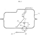
- the structure of a fuel tank 10 comprises a post 31 fixed upright on a drain plug 20 of the fuel tank 10 by a screw fit and a fuel level sensor 30 installed on the end portion of the post 31.
- the drain plug 20 is installed in the fuel tank 10 for removing fuel containing impurities.
- a thread is formed and on one end of the post 31, a screw portion is formed, so the post 31 is fixed on the inner side of the drain plug 20 with a screw fit.
- the fuel level sensor 30 is installed on the opposite end of the post 31, and connected to a warning light (not shown) and connector 33.
- a nut 32 is further comprised for setting a proper height "H" from the drain plug 20 and attaching the post 31 to the drain plug 20.
- the structure for installing a fuel level sensor in a fuel tank for automobiles of the present invention can be applied as a common use regardless of the shape of the fuel tank and the model of a car because the height of the post can be regulated, and can prevent malfunctions of a warning light of the fuel level sensor caused by abrupt braking, abrupt accelerating, and cornering.
Landscapes
- Physics & Mathematics (AREA)
- Fluid Mechanics (AREA)
- General Physics & Mathematics (AREA)
- Thermal Sciences (AREA)
- Engineering & Computer Science (AREA)
- Sustainable Development (AREA)
- Life Sciences & Earth Sciences (AREA)
- Sustainable Energy (AREA)
- Chemical & Material Sciences (AREA)
- Combustion & Propulsion (AREA)
- Transportation (AREA)
- Mechanical Engineering (AREA)
- Measurement Of Levels Of Liquids Or Fluent Solid Materials (AREA)
- Cooling, Air Intake And Gas Exhaust, And Fuel Tank Arrangements In Propulsion Units (AREA)
- Level Indicators Using A Float (AREA)
Abstract
Description
- The present invention relates to a structure for a fuel tank for automobiles, more particularly, a structure for installing a thermistor as a fuel level sensor for detecting the amount of fuel in a fuel tank, which can be applied as a common use regardless of the shape of the fuel tank and the model of a car and can prevent malfunctions of a warning light of a fuel level sensor caused by abrupt braking, abrupt accelerating, and cornering.
- As shown in FIG. 1 and FIG. 2, a general fuel tank comprises a fuel
gauge unit sensor 6 having a variable resister plate VR2 and afloat 3 installed on one end of a rod and the other end of the rod is installed on the variable resister plate VR2 pivotally. - The operation of the fuel gauge having above structure is as follows.
- The
float 3 and the rod move pivotally with respect to the level of fuel infuel tank 1 by the buoyancy, so the resistance of the variable resister plate VR2 varies according to the displacement of thefloat 3 and the rod. - Therefore, a driver knows the amount of the remaining fuel in the
fuel tank 1 from the indicator of thefuel gauge 7 operated by a voltage. - However, because it is possible that a driver is confused by the breakdown of the fuel gauge unit and the float when depending on only the fuel gauge unit, it further comprises a
fuel level sensor 4 for alarming a driver when amount of fuel in the fuel tank is less than a predetermined level. - The
fuel level sensor 4 comprises a thermistor VR1 installed on one end of apost 5 connected with the fuelgauge unit body 6. - When fuel level is over a predetermined level, because the thermistor VR1 is immersed in the fuel, the resistance has high value, so a
warning light 8 is not turned on. Whereas thewarning light 8 is turned on in case the thermistor VR1 comes out of the fuel when the fuel level is below a predetermined level, because the resistance has low value. - However the shape of the fuel tank is different according to a design of a car, the fuel gauge unit and the fuel level sensor having above structure must be newly designed.
- Moreover, there is a problem in that the position and the height of the fuel level sensor must be changed according to the capacity of the fuel tank and a fuel consumption of each design of a car.
- Also, it is possible that the warning light works badly when a driver puts on a brake or accelerates a car abruptly and corners a car. That is because the position of the fuel level sensor is nearer to base of the fuel tank than that of the fuel gauge unit in above structure, so the fuel level sensor is immersed and comes out of the fuel according to the slopping of the fuel from side to side.
- It is an object of the present invention to provide a structure for installing a fuel level sensor in a fuel tank for automobiles, which can be applied as a common use regardless of the shape of the fuel tank and the model of a car and can prevent malfunctions of a warning light of the fuel level sensor caused by abrupt braking, abrupt accelerating, and cornering.
- According to the aspect of the above object, there is provided a structure for installing a fuel level sensor in a fuel tank for automobiles, the structure comprising: a post fixed upright on a drain plug of a fuel tank by a screw fit; a fuel level sensor that is installed on the end portion of the post.
-
- FIG. 1 is a section view of a fuel tank of an automobile showing an installing structure for a fuel level sensor of prior art;
- FIG. 2 is a circuit diagram showing a connection of a fuel gauge and a warning light operated by a fuel level sensor;
- FIG. 3 is a section view of a fuel tank of an automobile showing an installing structure for a fuel level sensor of the present invention.
-
- The embodiment of the structure for installing a fuel sensor in a fuel tank fro automobiles of the present invention will be described with reference to the drawing.
- As shown in FIG. 3, the structure of a
fuel tank 10 comprises apost 31 fixed upright on adrain plug 20 of thefuel tank 10 by a screw fit and afuel level sensor 30 installed on the end portion of thepost 31. - The
drain plug 20 is installed in thefuel tank 10 for removing fuel containing impurities. - In the inner side of the
drain plug 20, a thread is formed and on one end of thepost 31, a screw portion is formed, so thepost 31 is fixed on the inner side of thedrain plug 20 with a screw fit. - The
fuel level sensor 30 is installed on the opposite end of thepost 31, and connected to a warning light (not shown) andconnector 33. - On the screw portion of the
post 31, anut 32 is further comprised for setting a proper height "H" from thedrain plug 20 and attaching thepost 31 to thedrain plug 20. - Therefore, it is not necessary to design
new post 31 in case of applying on a fuel tank having different shape to set a proper height. - As described above, the structure for installing a fuel level sensor in a fuel tank for automobiles of the present invention can be applied as a common use regardless of the shape of the fuel tank and the model of a car because the height of the post can be regulated, and can prevent malfunctions of a warning light of the fuel level sensor caused by abrupt braking, abrupt accelerating, and cornering.
Claims (2)
- Structure for installing a fuel level sensor in a fuel tank for automobiles, comprising:a post fixed upright on a drain plug of a fuel tank by a screw fit;a fuel level sensor that is installed on the end portion of the post.
- Structure for installing a fuel level sensor in a fuel tank for automobiles as claimed in claim 1, further comprising a nut in the opposite end portion of the post.
Applications Claiming Priority (2)
| Application Number | Priority Date | Filing Date | Title |
|---|---|---|---|
| KR10-2000-0046527A KR100387777B1 (en) | 2000-08-11 | 2000-08-11 | Structure for installing a fuel level sensor in a fuel tank for automobiles |
| KR2000046527 | 2000-08-11 |
Publications (1)
| Publication Number | Publication Date |
|---|---|
| EP1180666A1 true EP1180666A1 (en) | 2002-02-20 |
Family
ID=19682778
Family Applications (1)
| Application Number | Title | Priority Date | Filing Date |
|---|---|---|---|
| EP01105615A Withdrawn EP1180666A1 (en) | 2000-08-11 | 2001-03-06 | Structure for installing a fuel level sensor in a fuel tank for automobiles |
Country Status (4)
| Country | Link |
|---|---|
| US (1) | US6834545B2 (en) |
| EP (1) | EP1180666A1 (en) |
| JP (1) | JP3458126B2 (en) |
| KR (1) | KR100387777B1 (en) |
Families Citing this family (6)
| Publication number | Priority date | Publication date | Assignee | Title |
|---|---|---|---|---|
| DE10140678A1 (en) * | 2001-08-24 | 2003-03-13 | Sew Eurodrive Gmbh & Co | Combined sealing plug and vibration sensor for sealing a drive sump or oil reservoir and for providing vibration measurements, whereby the sensor is mounted in the head of the sealing plug in a tapped hole |
| JP2007126981A (en) * | 2005-11-01 | 2007-05-24 | Mitsubishi Electric Corp | Fuel supply device |
| EP2310814A4 (en) * | 2008-08-07 | 2014-01-15 | Illinois Tool Works | Liquid level sensing system |
| JP5985832B2 (en) * | 2012-02-06 | 2016-09-06 | 不双産業株式会社 | Solid assembly weighing device |
| CN104175872A (en) * | 2014-08-07 | 2014-12-03 | 东风裕隆汽车有限公司 | Method for quickly and safely discharging oil to automobile adopting electronic injection oil supply mode |
| JP5960764B2 (en) * | 2014-09-02 | 2016-08-02 | 本田技研工業株式会社 | Remaining fuel amount detection device for vehicle fuel tank |
Citations (6)
| Publication number | Priority date | Publication date | Assignee | Title |
|---|---|---|---|---|
| US3258968A (en) * | 1963-10-02 | 1966-07-05 | Stewart Warner Corp | Liquid level indicating device |
| US4121457A (en) * | 1976-06-25 | 1978-10-24 | Nippon Soken, Inc. | Liquid sensor |
| GB2065336A (en) * | 1979-11-23 | 1981-06-24 | Mackenzie J R S | Automatic level control system for an oil contaminant |
| US4410885A (en) * | 1981-12-23 | 1983-10-18 | Stenstrom Stephen M | Conductive fluid detecting method and apparatus |
| US4470301A (en) * | 1982-09-22 | 1984-09-11 | Fram Corporation | Probe and drain assembly for fuel oil/water separator |
| US4649898A (en) * | 1984-03-05 | 1987-03-17 | Martinson Monitors Inc. | Apparatus for controlling condensate level in steam retort |
Family Cites Families (26)
| Publication number | Priority date | Publication date | Assignee | Title |
|---|---|---|---|---|
| US1357986A (en) * | 1920-11-09 | of toledo | ||
| US695007A (en) * | 1900-01-02 | 1902-03-11 | Charles Strutt | Water-level indicator. |
| US1132833A (en) * | 1912-09-25 | 1915-03-23 | Jeffrey Mfg Co | Liquid-fuel tank. |
| US1357988A (en) * | 1919-04-18 | 1920-11-09 | Ind Res Corp | Fuel-reserve-supply system |
| US1613028A (en) * | 1925-01-13 | 1927-01-04 | Charles O Fisher | Gasoline-reserve control |
| US1714250A (en) * | 1927-03-14 | 1929-05-21 | Samuel S Stahl | Reserve valve for tanks |
| US1904793A (en) * | 1932-04-02 | 1933-04-18 | Lavoie Louis | Outlet control for liquid containers |
| US2191700A (en) * | 1938-04-19 | 1940-02-27 | George W Stetson | Liquid level controller |
| US2468676A (en) * | 1945-04-20 | 1949-04-26 | Premier Crystal Lab Inc | Level indicating device for fluent materials |
| US3326264A (en) * | 1964-11-05 | 1967-06-20 | Durrell U Howard | Reserve fuel systems |
| US4051726A (en) * | 1976-04-06 | 1977-10-04 | Hastbacka Albin A | Electro-optical liquid level indicator |
| US4342328A (en) | 1977-06-16 | 1982-08-03 | The United States Of America As Represented By The Secretary Of The Army | Two stage float valve |
| US4338907A (en) * | 1981-08-28 | 1982-07-13 | Lindbeck Laurel B | Gasoline fume generator and mixer |
| US4397333A (en) | 1981-09-04 | 1983-08-09 | Chrysler Corporation | Fuel collector assembly |
| DE3264452D1 (en) | 1982-02-25 | 1985-08-01 | Vdo Schindling | Suction device |
| US4454759A (en) * | 1982-05-10 | 1984-06-19 | Ogontz Controls Company | Fuel gauge for locomotives |
| US4591839A (en) * | 1982-05-20 | 1986-05-27 | Gulf & Western Manufacturing Company | System for detecting low liquid level and probe therefor |
| US4854406A (en) * | 1986-10-20 | 1989-08-08 | Breakthru Industries, Inc. | Weighing system |
| JPH05312621A (en) * | 1992-05-12 | 1993-11-22 | Hino Motors Ltd | Liquid level sensor |
| US5789665A (en) * | 1996-04-25 | 1998-08-04 | Voelker Sensors, Inc. | Oil quality sensor for use in a motor |
| GB2289542B (en) * | 1994-05-09 | 1998-08-26 | Automotive Tech Int | Method and apparatus for measuring the quantity of fuel in a land vehicle fuel tank subject to external forces |
| KR100250345B1 (en) * | 1996-12-31 | 2000-05-01 | 정몽규 | Remaining fuel detecting device of fuel tank |
| US5808187A (en) * | 1997-03-31 | 1998-09-15 | Ford Global Technologies, Inc. | Fluid level indicator |
| US6223765B1 (en) * | 1997-10-09 | 2001-05-01 | Marley Pump | Casing construction for fuel dispensing systems |
| JP2000145564A (en) * | 1998-11-05 | 2000-05-26 | Toyo Roki Mfg Co Ltd | Fuel supplying device |
| US6538261B1 (en) * | 2000-10-27 | 2003-03-25 | Delaware Capital Formation, Inc. | Wet line fluid removal system with optical sensor |
-
2000
- 2000-08-11 KR KR10-2000-0046527A patent/KR100387777B1/en not_active Expired - Fee Related
-
2001
- 2001-02-22 JP JP2001047224A patent/JP3458126B2/en not_active Expired - Fee Related
- 2001-03-06 EP EP01105615A patent/EP1180666A1/en not_active Withdrawn
- 2001-03-06 US US09/799,081 patent/US6834545B2/en not_active Expired - Fee Related
Patent Citations (6)
| Publication number | Priority date | Publication date | Assignee | Title |
|---|---|---|---|---|
| US3258968A (en) * | 1963-10-02 | 1966-07-05 | Stewart Warner Corp | Liquid level indicating device |
| US4121457A (en) * | 1976-06-25 | 1978-10-24 | Nippon Soken, Inc. | Liquid sensor |
| GB2065336A (en) * | 1979-11-23 | 1981-06-24 | Mackenzie J R S | Automatic level control system for an oil contaminant |
| US4410885A (en) * | 1981-12-23 | 1983-10-18 | Stenstrom Stephen M | Conductive fluid detecting method and apparatus |
| US4470301A (en) * | 1982-09-22 | 1984-09-11 | Fram Corporation | Probe and drain assembly for fuel oil/water separator |
| US4649898A (en) * | 1984-03-05 | 1987-03-17 | Martinson Monitors Inc. | Apparatus for controlling condensate level in steam retort |
Also Published As
| Publication number | Publication date |
|---|---|
| JP3458126B2 (en) | 2003-10-20 |
| KR20020013112A (en) | 2002-02-20 |
| JP2002059751A (en) | 2002-02-26 |
| US20020029631A1 (en) | 2002-03-14 |
| US6834545B2 (en) | 2004-12-28 |
| KR100387777B1 (en) | 2003-06-18 |
Similar Documents
| Publication | Publication Date | Title |
|---|---|---|
| US20040094913A1 (en) | Inclination-measuring device | |
| CN1423602A (en) | Device used to warn motorists of speeding on bends | |
| WO2012080437A1 (en) | Wading vehicle advisory speed display | |
| JP4534742B2 (en) | Rollover suppression control device for vehicle | |
| CN111551230A (en) | Method and system for detecting liquid level of oil tank in inclined state and vehicle-mounted terminal | |
| US6834545B2 (en) | Structure for installing a fuel level sensor in a fuel tank for automobiles | |
| CN110103813B (en) | Turn signal auxiliary control method and turn signal auxiliary control device | |
| US2866866A (en) | Fluid supply and level indicating system | |
| CN113954820A (en) | Drive control method, system, device, and storage medium for vehicle | |
| CN203305888U (en) | Automatic turn-on device of automobile left-turn signal lamp and automobile with same | |
| CN216742228U (en) | Steering oil tank assembly and vehicle with same | |
| CN211696597U (en) | Switch position sensor | |
| WO2003026939A1 (en) | An anti-skid apparatus for a vehicle | |
| CN107316776A (en) | A kind of collision sensing device | |
| CN107662643B (en) | Turning control method and system of vehicle and vehicle | |
| KR100506672B1 (en) | Method for conclusion fault of fuel sender for automobile | |
| KR200178026Y1 (en) | A fuel sender of non-contact type mounted with magnet | |
| CN217227689U (en) | Wheel position acquisition device and vehicle | |
| CN207403662U (en) | Automobile filter shell mounting structure | |
| JP2008203086A (en) | Fuel remaining amount notification device and saddle riding type vehicle | |
| JP2510970Y2 (en) | Tank level warning device | |
| KR100488776B1 (en) | Lighting system of fuel gauge alarm lamp for vehicle | |
| GB2555448A (en) | Fuel filter with water sensor, and sensor therefor | |
| JP2009029238A (en) | Fuel status notification system for fuel tank | |
| KR200196086Y1 (en) | Structure of vehicle cluster preventing indicator error |
Legal Events
| Date | Code | Title | Description |
|---|---|---|---|
| PUAI | Public reference made under article 153(3) epc to a published international application that has entered the european phase |
Free format text: ORIGINAL CODE: 0009012 |
|
| AK | Designated contracting states |
Kind code of ref document: A1 Designated state(s): AT BE CH CY DE DK ES FI FR GB GR IE IT LI LU MC NL PT SE TR Kind code of ref document: A1 Designated state(s): DE FR GB |
|
| AX | Request for extension of the european patent |
Free format text: AL;LT;LV;MK;RO;SI |
|
| 17P | Request for examination filed |
Effective date: 20020820 |
|
| AKX | Designation fees paid |
Free format text: DE FR GB |
|
| STAA | Information on the status of an ep patent application or granted ep patent |
Free format text: STATUS: THE APPLICATION HAS BEEN WITHDRAWN |
|
| 18W | Application withdrawn |
Effective date: 20050422 |