EP1180615A2 - Power transmission belt - Google Patents
Power transmission belt Download PDFInfo
- Publication number
- EP1180615A2 EP1180615A2 EP01118734A EP01118734A EP1180615A2 EP 1180615 A2 EP1180615 A2 EP 1180615A2 EP 01118734 A EP01118734 A EP 01118734A EP 01118734 A EP01118734 A EP 01118734A EP 1180615 A2 EP1180615 A2 EP 1180615A2
- Authority
- EP
- European Patent Office
- Prior art keywords
- power transmission
- transmission belt
- peroxide
- butyl
- thermoplastic
- Prior art date
- Legal status (The legal status is an assumption and is not a legal conclusion. Google has not performed a legal analysis and makes no representation as to the accuracy of the status listed.)
- Granted
Links
Images

Classifications
-
- F—MECHANICAL ENGINEERING; LIGHTING; HEATING; WEAPONS; BLASTING
- F16—ENGINEERING ELEMENTS AND UNITS; GENERAL MEASURES FOR PRODUCING AND MAINTAINING EFFECTIVE FUNCTIONING OF MACHINES OR INSTALLATIONS; THERMAL INSULATION IN GENERAL
- F16G—BELTS, CABLES, OR ROPES, PREDOMINANTLY USED FOR DRIVING PURPOSES; CHAINS; FITTINGS PREDOMINANTLY USED THEREFOR
- F16G1/00—Driving-belts
- F16G1/28—Driving-belts with a contact surface of special shape, e.g. toothed
-
- F—MECHANICAL ENGINEERING; LIGHTING; HEATING; WEAPONS; BLASTING
- F16—ENGINEERING ELEMENTS AND UNITS; GENERAL MEASURES FOR PRODUCING AND MAINTAINING EFFECTIVE FUNCTIONING OF MACHINES OR INSTALLATIONS; THERMAL INSULATION IN GENERAL
- F16G—BELTS, CABLES, OR ROPES, PREDOMINANTLY USED FOR DRIVING PURPOSES; CHAINS; FITTINGS PREDOMINANTLY USED THEREFOR
- F16G5/00—V-belts, i.e. belts of tapered cross-section
- F16G5/20—V-belts, i.e. belts of tapered cross-section with a contact surface of special shape, e.g. toothed
Definitions
- the present invention relates to a power transmission belt that is characterized by a layer of thermoplastic located between a fabric layer on the drive surface and the cushion section of the belt.
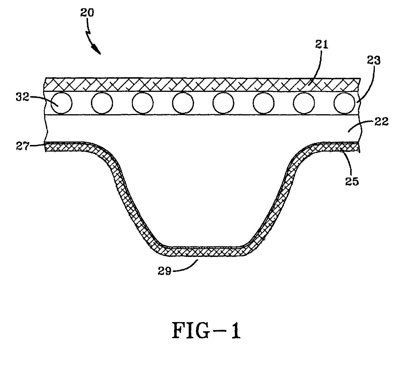
- Figure 1 is a fragmentary perspective view illustrating one embodiment of an endless power transmission belt of this invention.
- an endless power transmission belt comprising
- FIG. 1 of the drawing illustrates an endless power transmission belt structure or belt of this invention which is designated generally by the reference numeral 20.
- the belt 20 is particularly adapted to be used in associated sheaves in accordance with techniques known in the art.
- the belt is particularly suited for use in synchronous drive applications.
- the belt 20 is adapted to be used in so-called torque sensing drives, application where shock loads of varying belt tension are imposed on the belt, applications where the belt is operated at variable speeds, applications where the belt is spring-loaded to control its tension and the like.
- the belt 20 comprises a tension section or backing 21, a cushion section 22, a load-carrying section 23 disposed between the tension section 21 and cushion section 22, and a fabric layer 25 adhered to drive surface 29.
- the belt has a layer of thermoplastic 27 which is located between the cushion section 22 and the fabric layer 25 to prevent or decrease the amount of rubber with cushion section 22 permeating through the fabric 25 to the drive surface 29.
- the belts of the present invention there is at least one drive surface 29 having a fabric layer 25 bonded to the outer surface.
- the belt 20 may have multiple drive surfaces of two or more.
- the fabric layer may also be on the outer surface of the belt which is not a drive surface.
- the fabric layer 25 may be made from a woven, non-woven or knitted fabric.
- the fabrics for use in the present invention are made of conventional materials including nylon (such as nylon 4,6, nylon 6,6 and nylon 6), cotton, polyester, cotton/polyester, nylon/polyester, cotton/nylon, LycraTM (segmented polyurethane), aramid, rayon and the like.
- the fabric is made of nylon 6,6.
- the load-carrying section 23 has load-carrying means in the form of load-carrying cords 32 or filaments which are suitably embedded in an elastomeric load-carrying section 23 in accordance with techniques which are well known in the art.
- the cords may be transverse or parallel to the length of the belt.
- the cords 32 or filaments may be made of any suitable material known and used in the art. Representative examples of such materials include aramids, fiberglass, nylon, polyester, cotton, steel, carbon fiber and polybenzoxazole.
- the drive surface 29 of the belt 20 of Figure 1 is synchronous.
- the belts of the present invention also include those belts where the drive surface of the belt may be smooth, single V-grooved, and multi-V-grooved.
- Representative examples of synchronous include belts having trapezoidal or curvilinear teeth.
- the tooth design may have a helical offset tooth design such as shown in US-A- 5,209,705 and 5,421,789.
- the rubber compositions for use in the tension section 21, cushion section 22 and load-carrying section 23 may be the same or different.
- Conventional elastomers which may be used in one or both of these sections include natural rubber, polychloroprene, acrylonitrile-butadiene copolymers (NBR), polyisoprene, zinc salts of unsaturated carboxylic acid ester grafted hydrogenated nitrile butadiene elastomers, styrene-butadiene rubbers, polybutadiene, EPDM, hydrogenated acrylonitrile-butadiene copolymers (HNBR), polyurethane, elastomers marketed under the VitonTM designation and ethylene-acrylic elastomers sold under the name VAMAC and blends thereof.
- the elastomers for use in the tension section 21, cushion section 22 and load carrying section 23 may be crosslinked by various peroxide containing curing agents.
- Curing agents which may be employed in the compositions of the invention include, for example, di-tertbutyl peroxide, dicumyl peroxide, benzoyl peroxide, 2,4-dichlorobenzol peroxide, t-butyl-cumyl peroxide, t-butyl perbenzoate, t-butyl peroxide, t-butylperoxy (2-ethyl hexanoate), 2,5-dimethyl-2,5-di(benzoylperoxy)-hexane, benzoyl peroxide, 2,5-dimethyl-2,5-(t-butyl peroxy)-hexane, 1,1-ditert-butyl peroxy-3,3,5-trimethyl cyclohexane, 4,4-ditert-butyl peroxy n
- Additional curing agents which may be employed include diacyl or dialkyl peroxides such as ⁇ , ⁇ '-bis(t-butylperoxy)-isopropylbenzene, 2,5-dimethyl-2,5-di(t-butylperoxy) hexane, di-t-butyl peroxide, 2,5-dimethyl-2,5-di-(t-butylperoxy)hexyne-3, lauroyl peroxide, t-butyl hydroperoxide, t-amyl hydroperoxide, cumene hydroperoxide, t-butyl perbenzoate, t-butyl peroxide, t-butylperoxy (2-ethyl hexanoate), 2,5-dimethyl-2,5-di (benzoylperoxy)-hexane and benzoyl peroxide. All of the above curing agents are commercially available.
- diacyl or dialkyl peroxides
- the amount of curing agent that is used may vary. Generally speaking, the level will range of from 0.1 to 10 phr (based on active parts of peroxide). Preferably, the level ranges from 1.8 to 3.0 phr.
- thermoplastic 27 there is one drive surface 29 having a fabric layer 25 bonded to the outer surface. Between the fabric layer 25 and the cushion section is the layer of thermoplastic 27.
- the thermoplastics which may be used in the present invention are well known to those skilled in the art. Generally speaking, the thermoplastic should have a melting point of from 82°C to 265°C.
- thermoplastic is polyvinylidene fluoride.
- the polyvinylidene fluoride layer may be the homopolymer of vinylidene fluoride or a copolymer of vinylidene fluoride and another monomer.
- One or more monomers selected from the group consisting of tetrafluoroethylene, hexafluoropropylene, monochlorotrifluoroethylene, vinyl fluoride, perfluorovinylalkyl ethers, vinyl acetate and ethylene can be used for copolymerization with vinylidene fluoride.
- the thermoplastic fluoride layer is preferably applied in the form of a film.
- the film is generally transparent and may be an unoriented film produced by the techniques of extrusion or casting or an oriented film obtained by stretching the unoriented film.
- films of polyvinylidene fluoride may be used to construct the belts of the present invention.
- Such films include those that are commercially available from Westlake Plastics Company of Lenni, Pennsylvania.
- the thickness of the thermoplastic layer may vary. Generally speaking, the thickness may range from 0.0125 mm (0.5 mil) to 1.25 mm (50 mils). Preferably, the thickness ranges from 0.05 mm (2 mils) to 0.20 mm (8 mils).
- thermoplastic layer 27 may be applied to the fabric and heated to adhere the thermoplastic to the fabric. Preferably, this is done prior to application of the fabric to the cushion section 22 during construction of the belt 20.
- the power transmission belts may be built on a drum device. First, the fabric and thermoplastic layer are applied to the drum. Next, the cord or tensile member (load carrying section) is spiraled onto the drum. Thereafter, the cushion section is applied onto the tension section.
- the thermoplastic layer or film may be heat bonded to the facing fabric and thereafter laminated onto the cushion section. Another alternative is to apply the thermoplastic layer film and fabric separately relying on the heat during cure to mechanically bond the two layers.
- the assembled laminate or slab is then placed in a mold, cured and cut into the belts in a manner known to those skilled in the art.
- the belts of the present invention were prepared in the following manner.
- a resorcinol formaldehyde latex dipped nylon 6,6 knit fabric was laminated with 0.1 mm of a polyvinylidene fluoride film obtained from Westlake Plastic Company.
- the filer was laminated to the fabric in a flat platen press at 191°C.
- This fabric laminate was placed on the drum with the polyvinylidene fluoride layer out.
- Fiberglass cord dipped in an adhesive was spiraled onto the drum.
- a rubber sheet of hydrogenated NBR was applied onto the cord to form the cushion section.
- a cotton/polyester fabric backing was applied to the drum device.
- the belts were cured at 176°C and cut in widths of 32 mm (1.25 inches).
Landscapes
- Engineering & Computer Science (AREA)
- General Engineering & Computer Science (AREA)
- Mechanical Engineering (AREA)
- Laminated Bodies (AREA)
- Devices For Conveying Motion By Means Of Endless Flexible Members (AREA)
- Woven Fabrics (AREA)
- Compositions Of Macromolecular Compounds (AREA)
Abstract
Description
- Recent developments in the automotive industry have resulted in an increase in the demands on the properties of power transmission belts. As a result, power transmission belts on these engines have been required to operate under higher loads, at higher speeds and at higher temperatures while reducing belt width and noise. The automotive industry demands a high quality belt capable of withstanding these severe conditions. One method to improve the properties of such belts has been to improve the materials from which the belts are made. For example, conventional polychloroprene rubber has been replaced with hydrogenated nitrile rubber and chlorosulfonated polyethylene. In addition, solid lubricants have been added to the rubber compositions to improve the abrasion properties of the belt by reducing the coefficient of friction.
- The present invention relates to a power transmission belt that is characterized by a layer of thermoplastic located between a fabric layer on the drive surface and the cushion section of the belt.
- The accompanying figures show embodiments of this invention in which Figure 1 is a fragmentary perspective view illustrating one embodiment of an endless power transmission belt of this invention.
- There is disclosed an endless power transmission belt comprising
- (a) a tension section;
- (b) a cushion section;
- (c) a load-carrying section disposed between said tension section and cushion section;
- (d) at least one drive surface having a fabric layer bonded to an outer surface of the belt; and
- (e) a layer of thermoplastic located between the fabric layer and the cushion section of the power transmission belt.
-
- Reference is now made to Figure 1 of the drawing which illustrates an endless power transmission belt structure or belt of this invention which is designated generally by the
reference numeral 20. Thebelt 20 is particularly adapted to be used in associated sheaves in accordance with techniques known in the art. The belt is particularly suited for use in synchronous drive applications. Thebelt 20 is adapted to be used in so-called torque sensing drives, application where shock loads of varying belt tension are imposed on the belt, applications where the belt is operated at variable speeds, applications where the belt is spring-loaded to control its tension and the like. - The
belt 20 comprises a tension section or backing 21, acushion section 22, a load-carryingsection 23 disposed between thetension section 21 andcushion section 22, and afabric layer 25 adhered to drivesurface 29. The belt has a layer of thermoplastic 27 which is located between thecushion section 22 and thefabric layer 25 to prevent or decrease the amount of rubber withcushion section 22 permeating through thefabric 25 to thedrive surface 29. - In the belts of the present invention, there is at least one
drive surface 29 having afabric layer 25 bonded to the outer surface. In the embodiment shown in Figure 1, there is onedrive surface 29 having afabric layer 25. In accordance with other embodiments, thebelt 20 may have multiple drive surfaces of two or more. The fabric layer may also be on the outer surface of the belt which is not a drive surface. - The
fabric layer 25 may be made from a woven, non-woven or knitted fabric. The fabrics for use in the present invention are made of conventional materials including nylon (such as nylon 4,6, nylon 6,6 and nylon 6), cotton, polyester, cotton/polyester, nylon/polyester, cotton/nylon, Lycra™ (segmented polyurethane), aramid, rayon and the like. Preferably, the fabric is made of nylon 6,6. - The load-carrying
section 23 has load-carrying means in the form of load-carryingcords 32 or filaments which are suitably embedded in an elastomeric load-carryingsection 23 in accordance with techniques which are well known in the art. The cords may be transverse or parallel to the length of the belt. Thecords 32 or filaments may be made of any suitable material known and used in the art. Representative examples of such materials include aramids, fiberglass, nylon, polyester, cotton, steel, carbon fiber and polybenzoxazole. - The
drive surface 29 of thebelt 20 of Figure 1 is synchronous. In accordance with other embodiments and as discussed later, it is contemplated herein the belts of the present invention also include those belts where the drive surface of the belt may be smooth, single V-grooved, and multi-V-grooved. Representative examples of synchronous include belts having trapezoidal or curvilinear teeth. The tooth design may have a helical offset tooth design such as shown in US-A- 5,209,705 and 5,421,789. - The rubber compositions for use in the
tension section 21,cushion section 22 and load-carryingsection 23 may be the same or different. Conventional elastomers which may be used in one or both of these sections include natural rubber, polychloroprene, acrylonitrile-butadiene copolymers (NBR), polyisoprene, zinc salts of unsaturated carboxylic acid ester grafted hydrogenated nitrile butadiene elastomers, styrene-butadiene rubbers, polybutadiene, EPDM, hydrogenated acrylonitrile-butadiene copolymers (HNBR), polyurethane, elastomers marketed under the Viton™ designation and ethylene-acrylic elastomers sold under the name VAMAC and blends thereof. - The elastomers for use in the
tension section 21,cushion section 22 andload carrying section 23 may be crosslinked by various peroxide containing curing agents. Curing agents which may be employed in the compositions of the invention include, for example, di-tertbutyl peroxide, dicumyl peroxide, benzoyl peroxide, 2,4-dichlorobenzol peroxide, t-butyl-cumyl peroxide, t-butyl perbenzoate, t-butyl peroxide, t-butylperoxy (2-ethyl hexanoate), 2,5-dimethyl-2,5-di(benzoylperoxy)-hexane, benzoyl peroxide, 2,5-dimethyl-2,5-(t-butyl peroxy)-hexane, 1,1-ditert-butyl peroxy-3,3,5-trimethyl cyclohexane, 4,4-ditert-butyl peroxy n-butyl valerate and n-butyl-4,4-bis(t-butyl peroxy) valerate. Additional curing agents which may be employed include diacyl or dialkyl peroxides such as α,α'-bis(t-butylperoxy)-isopropylbenzene, 2,5-dimethyl-2,5-di(t-butylperoxy) hexane, di-t-butyl peroxide, 2,5-dimethyl-2,5-di-(t-butylperoxy)hexyne-3, lauroyl peroxide, t-butyl hydroperoxide, t-amyl hydroperoxide, cumene hydroperoxide, t-butyl perbenzoate, t-butyl peroxide, t-butylperoxy (2-ethyl hexanoate), 2,5-dimethyl-2,5-di (benzoylperoxy)-hexane and benzoyl peroxide. All of the above curing agents are commercially available. - The amount of curing agent that is used may vary. Generally speaking, the level will range of from 0.1 to 10 phr (based on active parts of peroxide). Preferably, the level ranges from 1.8 to 3.0 phr.
- In the belt of Figure 1, there is one
drive surface 29 having afabric layer 25 bonded to the outer surface. Between thefabric layer 25 and the cushion section is the layer of thermoplastic 27. The thermoplastics which may be used in the present invention are well known to those skilled in the art. Generally speaking, the thermoplastic should have a melting point of from 82°C to 265°C. Amongst those which can be used include polyethylene, polypropylene, polystyrene, acrylonitrile-butadienestyrene, polybutylene terephthalate, polyamide 6, polyamide 66, polyamide 7, polyamide 11, polyamide 12, polyvinyl fluoride, polyvinyl chloride, polyether, polybutylenes, polyamides, polycarbonates, polyether amides, polyurethanes and polyvinylidene fluoride. Preferably, the thermoplastic is polyvinylidene fluoride. The polyvinylidene fluoride layer may be the homopolymer of vinylidene fluoride or a copolymer of vinylidene fluoride and another monomer. One or more monomers selected from the group consisting of tetrafluoroethylene, hexafluoropropylene, monochlorotrifluoroethylene, vinyl fluoride, perfluorovinylalkyl ethers, vinyl acetate and ethylene can be used for copolymerization with vinylidene fluoride. - The thermoplastic fluoride layer is preferably applied in the form of a film. The film is generally transparent and may be an unoriented film produced by the techniques of extrusion or casting or an oriented film obtained by stretching the unoriented film.
- Commercially available films of polyvinylidene fluoride may be used to construct the belts of the present invention. Such films include those that are commercially available from Westlake Plastics Company of Lenni, Pennsylvania.
- The thickness of the thermoplastic layer may vary. Generally speaking, the thickness may range from 0.0125 mm (0.5 mil) to 1.25 mm (50 mils). Preferably, the thickness ranges from 0.05 mm (2 mils) to 0.20 mm (8 mils).
- The
thermoplastic layer 27 may be applied to the fabric and heated to adhere the thermoplastic to the fabric. Preferably, this is done prior to application of the fabric to thecushion section 22 during construction of thebelt 20. - The power transmission belts may be built on a drum device. First, the fabric and thermoplastic layer are applied to the drum. Next, the cord or tensile member (load carrying section) is spiraled onto the drum. Thereafter, the cushion section is applied onto the tension section. The thermoplastic layer or film may be heat bonded to the facing fabric and thereafter laminated onto the cushion section. Another alternative is to apply the thermoplastic layer film and fabric separately relying on the heat during cure to mechanically bond the two layers. The assembled laminate or slab is then placed in a mold, cured and cut into the belts in a manner known to those skilled in the art.
- The belts of the present invention were prepared in the following manner. A resorcinol formaldehyde latex dipped nylon 6,6 knit fabric was laminated with 0.1 mm of a polyvinylidene fluoride film obtained from Westlake Plastic Company. The filer was laminated to the fabric in a flat platen press at 191°C. This fabric laminate was placed on the drum with the polyvinylidene fluoride layer out. Fiberglass cord dipped in an adhesive was spiraled onto the drum. A rubber sheet of hydrogenated NBR was applied onto the cord to form the cushion section. Finally, a cotton/polyester fabric backing was applied to the drum device. The belts were cured at 176°C and cut in widths of 32 mm (1.25 inches).
Claims (10)
- An endless power transmission belt characterized by(a) a tension section (21);(b) a cushion section (22);(c) a load-carrying section (23) disposed between said tension section and cushion section;(d) at least one drive surface (29) having a fabric layer (25) bonded to an outer surface of the belt; and(e) a layer of thermoplastic (27) located between the fabric layer (25) and the cushion section (22) of the power transmission belt.
- The power transmission belt of claim 1 wherein the layer of thermoplastic (27) ranges from 0.0125 mm to 1.25 mm thick.
- The power transmission belt of claim 1 wherein said thermoplastic is selected from the group consisting of polyvinylidene fluoride, polyethylene, polypropylene, polystyrene, acrylonitrile-butadiene-styrene, polybutylene terephthalate, polyamide 6, polyamide 66, polyamide 7, polyamide 11, polyamide 12, polyvinyl fluoride, polyvinyl chloride, polyether, polybutylenes, polyamides, polycarbonates, polyether amides, polyurethanes and polyvinylidene fluoride.
- The power transmission belt of claim 3 wherein said thermoplastic is polyvinylidene fluoride.
- The power transmission belt of claim 1 wherein said thermoplastic has a melting point ranging from 82°C to 265°C.
- The power transmission belt of claim 1 wherein the fabric layer (25) is selected from the group consisting of woven, non-woven and knitted fabrics.
- The power transmission belt of claim 1 wherein a peroxide containing curing agent is present.
- The power transmission belt of claim 7 wherein said peroxide containing curing agent is selected from the group consisting of di-tertbutyl peroxide, dicumyl peroxide, benzoyl peroxide, 2,4-dichlorobenzol peroxide, t-butyl-cumyl peroxide, t-butyl perbenzoate, t-butyl peroxide, t-butylperoxy (2-ethyl hexanoate), 2,5-dimethyl-2,5-di (benzoylperoxy)-hexane, benzoyl peroxide, 2,5-dimethyl-2,5-(t-butyl peroxy)-hexane, 1,1-ditert-butyl peroxy-3,3,5-trimethyl cyclohexane, 4,4-ditert-butyl peroxy n-butyl valerate, n-butyl-4,4-bis (t-butyl peroxy) valerate, α,α-bis(t-butylperoxy)-isopropylbenzene, 2,5-dimethyl-2,5-di(5-butylperoxy) hexane, di-t-butyl peroxide, 2,5-dimethyl-2,5-di-(t-butylperoxy)hexyne-3, lauroyl peroxide, t-butyl hydroperoxide, t-amyl hydroperoxide, cumene hydroperoxide, t-butyl perbenzoate, t-butyl peroxide, t-butylperoxy (2-ethyl hexanoate), 2,5-dimethyl-2,5-di(benzoylperoxy)-hexane, benzoyl peroxide and mixtures thereof.
- The power transmission belt of claim 4 wherein said polyvinylidene fluoride is selected from the group consisting of a homopolymer of vinylidene fluoride and copolymers of vinylidene fluoride and another monomer.
- The power transmission belt of claim 9 wherein said additional monomer is selected from the group consisting of tetrafluoroethylene, hexafluoropropylene, monochlorotrifluoroethylene, vinyl fluoride, perfluorovinylalkyl ethers, vinyl acetate and ethylene.
Applications Claiming Priority (2)
| Application Number | Priority Date | Filing Date | Title |
|---|---|---|---|
| US638633 | 2000-08-14 | ||
| US09/638,633 US6443866B1 (en) | 2000-08-14 | 2000-08-14 | Power transmission belt |
Publications (3)
| Publication Number | Publication Date |
|---|---|
| EP1180615A2 true EP1180615A2 (en) | 2002-02-20 |
| EP1180615A3 EP1180615A3 (en) | 2003-09-03 |
| EP1180615B1 EP1180615B1 (en) | 2005-11-23 |
Family
ID=24560823
Family Applications (1)
| Application Number | Title | Priority Date | Filing Date |
|---|---|---|---|
| EP01118734A Expired - Lifetime EP1180615B1 (en) | 2000-08-14 | 2001-08-06 | Power transmission belt |
Country Status (5)
| Country | Link |
|---|---|
| US (1) | US6443866B1 (en) |
| EP (1) | EP1180615B1 (en) |
| JP (1) | JP2002122187A (en) |
| BR (1) | BR0106685A (en) |
| DE (1) | DE60115166T2 (en) |
Cited By (7)
| Publication number | Priority date | Publication date | Assignee | Title |
|---|---|---|---|---|
| WO2004011822A1 (en) * | 2002-07-29 | 2004-02-05 | The Gates Corporation | Belt |
| EP1696150A1 (en) * | 2005-02-28 | 2006-08-30 | Megadyne S.r.l. | Toothed belt |
| EP2166251A1 (en) | 2008-09-23 | 2010-03-24 | Hutchinson | Power transmission belt |
| WO2013091809A1 (en) * | 2011-12-20 | 2013-06-27 | Arntz Beteiligungs Gmbh & Co. Kg | Belt having a textile overlay |
| WO2013091808A1 (en) * | 2011-12-20 | 2013-06-27 | Arntz Beteiligungs Gmbh & Co. Kg | Belt having a multilayer impregnated textile overlay |
| DE102008037561B4 (en) | 2008-11-18 | 2020-06-18 | Contitech Antriebssysteme Gmbh | Articles, in particular drive belts, with a textile covering and method for producing a drive belt |
| DE102008055497B4 (en) | 2008-12-10 | 2020-06-18 | Contitech Antriebssysteme Gmbh | Elastic article, in particular drive belt, with a textile cover and an adhesion promoter made of meltable plastic |
Families Citing this family (20)
| Publication number | Priority date | Publication date | Assignee | Title |
|---|---|---|---|---|
| IT1320359B1 (en) * | 2000-05-23 | 2003-11-26 | Dayco Europe Srl | TOOTHED BELT. |
| US6750293B2 (en) * | 2001-03-29 | 2004-06-15 | Alliant Techsystems, Inc. | High-strength rubber formulations, and shear ply made from the same |
| WO2002084144A1 (en) * | 2001-04-12 | 2002-10-24 | The Gates Corporation | Thermoplastic jacket belt |
| US7025699B2 (en) * | 2003-04-23 | 2006-04-11 | Dayco Products, Llc | Elastomer composition for power transmission belt tooth facing |
| US20060084543A1 (en) * | 2004-10-20 | 2006-04-20 | The Goodyear Tire & Rubber Company. | Apparatus and method for controlling rubber flow in positive drive belts |
| FR2898171B1 (en) * | 2006-03-03 | 2009-02-27 | Hutchinson Sa | POWER TRANSMISSION BELT. |
| US7909719B2 (en) * | 2008-03-14 | 2011-03-22 | Forbo Siegling, Llc | Belt |
| KR101992943B1 (en) | 2012-01-11 | 2019-06-25 | 반도 카가쿠 가부시키가이샤 | Friction transmission belt, manufacturing method thereof, and belt transmission device |
| ITTO20120419A1 (en) * | 2012-05-09 | 2013-11-10 | Dayco Europe Srl | POLI-V BELT INCLUDING A LAYER OF THERMOPLASTIC MATERIAL AND A KNITTED FABRIC IMMERSED IN AN ELASTOMERIC LAYER |
| JP6059004B2 (en) * | 2012-12-26 | 2017-01-11 | 三ツ星ベルト株式会社 | Transmission belt and manufacturing method thereof |
| JP6023736B2 (en) * | 2013-03-29 | 2016-11-09 | 三ツ星ベルト株式会社 | V-ribbed belt |
| EP2881342B1 (en) * | 2013-08-02 | 2016-12-14 | Veyance Technologies, Inc. | Conveyor belt |
| FR3019609B1 (en) * | 2014-04-03 | 2016-05-13 | Hutchinson | POWER TRANSMISSION BELT. |
| US9829066B2 (en) | 2014-04-07 | 2017-11-28 | Gates Corporation | Electrically conductive power transmission belt |
| DE102014008622A1 (en) * | 2014-06-17 | 2015-12-17 | Arntz Beteiligungs Gmbh & Co. Kg | Power transmission belt with a polyethylene coating |
| JP6748133B2 (en) * | 2017-03-21 | 2020-08-26 | 三ツ星ベルト株式会社 | Friction transmission belt and manufacturing method thereof |
| EP3820686B1 (en) * | 2018-07-10 | 2022-09-21 | Walther Flender GmbH | Method for producing driving belts |
| DE102018221886A1 (en) * | 2018-12-17 | 2020-06-18 | Contitech Antriebssysteme Gmbh | belt |
| US12123475B2 (en) * | 2020-01-16 | 2024-10-22 | Mitsuboshi Belting Ltd. | Core wire for drive belt, drive belt, and method for manufacturing core wire and drive belt |
| JP7323560B2 (en) | 2021-01-29 | 2023-08-08 | バンドー化学株式会社 | friction transmission belt |
Citations (1)
| Publication number | Priority date | Publication date | Assignee | Title |
|---|---|---|---|---|
| US5209705A (en) | 1992-05-29 | 1993-05-11 | The Goodyear Tire & Rubber Company | Synchronous drive belt with oblique and offset teeth |
Family Cites Families (18)
| Publication number | Priority date | Publication date | Assignee | Title |
|---|---|---|---|---|
| US3964328A (en) | 1973-09-07 | 1976-06-22 | The Gates Rubber Company | Elastomer-free fabric surface for power transmission belt tooth facing |
| US3894900A (en) | 1973-09-07 | 1975-07-15 | Gates Rubber Co | Elastomer-free fabric surface for power transmission belt tooth facing |
| US4066732A (en) | 1976-11-19 | 1978-01-03 | The Gates Rubber Company | Toothed belt making |
| US4246055A (en) | 1979-09-04 | 1981-01-20 | Dayco Corporation | Method of making an endless power transmission belt |
| US4692291A (en) * | 1980-04-14 | 1987-09-08 | Union Carbide Corporation | Molding method using fast curing fiber reinforced, low viscosity thermosetting resin |
| US4571230A (en) * | 1984-09-04 | 1986-02-18 | Dayco Corporation | Endless power transmission belt having a toothed compression section and method of making the same |
| DE3880710T2 (en) | 1987-02-27 | 1993-12-02 | Nitta Kk | Manufacturing process for endless belts. |
| US4952293A (en) | 1989-12-29 | 1990-08-28 | Xerox Corporation | Polymer electrodeposition process |
| JPH0434253A (en) * | 1990-05-29 | 1992-02-05 | Bando Chem Ind Ltd | toothed belt |
| JPH04151048A (en) * | 1990-10-09 | 1992-05-25 | Mitsuboshi Belting Ltd | V-ribbed and manufacture of belt thereof |
| US5112282A (en) * | 1990-12-27 | 1992-05-12 | The Gates Rubber Company | High temperature polyurethane belt |
| ES2104140T3 (en) | 1992-03-02 | 1997-10-01 | Dayco Products Inc | BELT STRUCTURE ESSENTIALLY FORMED OF THERMOPLASTIC MATERIAL, AND MANUFACTURING PROCEDURE THEREOF. |
| US5610217A (en) * | 1994-10-31 | 1997-03-11 | The Gates Corporation | Ethylene-alpha-olefin belting |
| US5464488A (en) * | 1994-12-22 | 1995-11-07 | Albany International Corp. | Method of seaming plastic fabrics |
| EP0780594A1 (en) | 1995-12-21 | 1997-06-25 | Elf Atochem S.A. | Antistatic belts |
| CA2203617C (en) * | 1996-04-26 | 2000-08-08 | Hiroshi Jonen | Power transmission belt |
| US5971879A (en) * | 1997-04-22 | 1999-10-26 | The Gates Corporation | Belt reinforcing material and belt constructed therewith |
| US6409621B1 (en) * | 2000-05-12 | 2002-06-25 | The Goodyear Tire & Rubber Company | Power transmission belt |
-
2000
- 2000-08-14 US US09/638,633 patent/US6443866B1/en not_active Expired - Fee Related
-
2001
- 2001-08-06 DE DE60115166T patent/DE60115166T2/en not_active Expired - Fee Related
- 2001-08-06 EP EP01118734A patent/EP1180615B1/en not_active Expired - Lifetime
- 2001-08-07 BR BR0106685-4A patent/BR0106685A/en not_active Application Discontinuation
- 2001-08-09 JP JP2001241842A patent/JP2002122187A/en not_active Withdrawn
Patent Citations (2)
| Publication number | Priority date | Publication date | Assignee | Title |
|---|---|---|---|---|
| US5209705A (en) | 1992-05-29 | 1993-05-11 | The Goodyear Tire & Rubber Company | Synchronous drive belt with oblique and offset teeth |
| US5421789A (en) | 1992-05-29 | 1995-06-06 | The Goodyear Tire & Rubber Company | Synchronous drive pulley and its combination with a belt having oblique and offset teeth |
Cited By (11)
| Publication number | Priority date | Publication date | Assignee | Title |
|---|---|---|---|---|
| WO2004011822A1 (en) * | 2002-07-29 | 2004-02-05 | The Gates Corporation | Belt |
| EP1696150A1 (en) * | 2005-02-28 | 2006-08-30 | Megadyne S.r.l. | Toothed belt |
| EP2166251A1 (en) | 2008-09-23 | 2010-03-24 | Hutchinson | Power transmission belt |
| US8293357B2 (en) | 2008-09-23 | 2012-10-23 | Hutchinson | Power transmission belt |
| DE102008037561B4 (en) | 2008-11-18 | 2020-06-18 | Contitech Antriebssysteme Gmbh | Articles, in particular drive belts, with a textile covering and method for producing a drive belt |
| DE102008055497B4 (en) | 2008-12-10 | 2020-06-18 | Contitech Antriebssysteme Gmbh | Elastic article, in particular drive belt, with a textile cover and an adhesion promoter made of meltable plastic |
| WO2013091809A1 (en) * | 2011-12-20 | 2013-06-27 | Arntz Beteiligungs Gmbh & Co. Kg | Belt having a textile overlay |
| WO2013091808A1 (en) * | 2011-12-20 | 2013-06-27 | Arntz Beteiligungs Gmbh & Co. Kg | Belt having a multilayer impregnated textile overlay |
| EP3109508A1 (en) * | 2011-12-20 | 2016-12-28 | Arntz Beteiligungs GmbH & Co. KG | Belt having a textile overlay |
| US9644706B2 (en) | 2011-12-20 | 2017-05-09 | Arntz Beteiligungs Gmbh & Co. Kg | Belt having a multilayer impregnated textile overlay |
| AU2012359250B2 (en) * | 2011-12-20 | 2017-06-22 | Arntz Beteiligungs Gmbh & Co. Kg | Belt having a textile overlay |
Also Published As
| Publication number | Publication date |
|---|---|
| JP2002122187A (en) | 2002-04-26 |
| EP1180615B1 (en) | 2005-11-23 |
| DE60115166T2 (en) | 2006-08-10 |
| US6443866B1 (en) | 2002-09-03 |
| DE60115166D1 (en) | 2005-12-29 |
| EP1180615A3 (en) | 2003-09-03 |
| BR0106685A (en) | 2002-05-21 |
Similar Documents
| Publication | Publication Date | Title |
|---|---|---|
| US6443866B1 (en) | Power transmission belt | |
| EP1154171B1 (en) | Power transmission belt | |
| EP1930622B1 (en) | Power transmission belts | |
| US8507391B2 (en) | Elastic articles, particularly drive belts, having a textile overlay and a bonding agent made from meltable plastic | |
| KR100379880B1 (en) | Wear resistant belts, and a process for their manufacture | |
| US20170299017A1 (en) | Cross linked elastomeric facing on cast polyurethane synchronous drive belts | |
| US20070155566A1 (en) | Power transmission belt | |
| TWI273030B (en) | Belt | |
| EP1225368B1 (en) | Fabric cushion V-ribbed belt | |
| US5478286A (en) | Synchronous belt | |
| EP4314595B1 (en) | Power transmission belt and its transmission system | |
| EP1650472A2 (en) | Apparatus and method for controlling rubber flow in positive drive belts | |
| JP2009051204A (en) | Cogged v-belt and its manufacturing method | |
| JP2007144714A (en) | Manufacturing method of v-belt | |
| WO2024165985A1 (en) | Power transmittion belt and corresponding transmission system | |
| JP2908250B2 (en) | V-ribbed belt | |
| JP4634986B2 (en) | Transmission flat belt | |
| JPH07293641A (en) | Ribbed belt | |
| JP2020041693A (en) | Transmission V-belt and method of manufacturing the same | |
| JP2006282763A (en) | METHOD FOR PRODUCING BONDED BODY OF ETHYLENE-alpha-OLEFIN ELASTOMER COMPOSITION AND FIBER AND POWER TRANSMISSION BELT | |
| JP2001099235A (en) | Speed change belt | |
| AU2003253659A1 (en) | Power transmission belt |
Legal Events
| Date | Code | Title | Description |
|---|---|---|---|
| PUAI | Public reference made under article 153(3) epc to a published international application that has entered the european phase |
Free format text: ORIGINAL CODE: 0009012 |
|
| AK | Designated contracting states |
Kind code of ref document: A2 Designated state(s): AT BE CH CY DE DK ES FI FR GB GR IE IT LI LU MC NL PT SE TR |
|
| AX | Request for extension of the european patent |
Free format text: AL;LT;LV;MK;RO;SI |
|
| PUAL | Search report despatched |
Free format text: ORIGINAL CODE: 0009013 |
|
| AK | Designated contracting states |
Kind code of ref document: A3 Designated state(s): AT BE CH CY DE DK ES FI FR GB GR IE IT LI LU MC NL PT SE TR |
|
| AX | Request for extension of the european patent |
Extension state: AL LT LV MK RO SI |
|
| 17P | Request for examination filed |
Effective date: 20040303 |
|
| AKX | Designation fees paid |
Designated state(s): DE FR GB |
|
| 17Q | First examination report despatched |
Effective date: 20040721 |
|
| GRAP | Despatch of communication of intention to grant a patent |
Free format text: ORIGINAL CODE: EPIDOSNIGR1 |
|
| GRAS | Grant fee paid |
Free format text: ORIGINAL CODE: EPIDOSNIGR3 |
|
| GRAA | (expected) grant |
Free format text: ORIGINAL CODE: 0009210 |
|
| AK | Designated contracting states |
Kind code of ref document: B1 Designated state(s): DE FR GB |
|
| REG | Reference to a national code |
Ref country code: GB Ref legal event code: FG4D |
|
| REF | Corresponds to: |
Ref document number: 60115166 Country of ref document: DE Date of ref document: 20051229 Kind code of ref document: P |
|
| ET | Fr: translation filed | ||
| PLBE | No opposition filed within time limit |
Free format text: ORIGINAL CODE: 0009261 |
|
| STAA | Information on the status of an ep patent application or granted ep patent |
Free format text: STATUS: NO OPPOSITION FILED WITHIN TIME LIMIT |
|
| 26N | No opposition filed |
Effective date: 20060824 |
|
| PGFP | Annual fee paid to national office [announced via postgrant information from national office to epo] |
Ref country code: DE Payment date: 20070831 Year of fee payment: 7 |
|
| PGFP | Annual fee paid to national office [announced via postgrant information from national office to epo] |
Ref country code: GB Payment date: 20070705 Year of fee payment: 7 |
|
| PGFP | Annual fee paid to national office [announced via postgrant information from national office to epo] |
Ref country code: FR Payment date: 20070803 Year of fee payment: 7 |
|
| GBPC | Gb: european patent ceased through non-payment of renewal fee |
Effective date: 20080806 |
|
| REG | Reference to a national code |
Ref country code: FR Ref legal event code: ST Effective date: 20090430 |
|
| PG25 | Lapsed in a contracting state [announced via postgrant information from national office to epo] |
Ref country code: FR Free format text: LAPSE BECAUSE OF NON-PAYMENT OF DUE FEES Effective date: 20080901 Ref country code: DE Free format text: LAPSE BECAUSE OF NON-PAYMENT OF DUE FEES Effective date: 20090303 |
|
| PG25 | Lapsed in a contracting state [announced via postgrant information from national office to epo] |
Ref country code: GB Free format text: LAPSE BECAUSE OF NON-PAYMENT OF DUE FEES Effective date: 20080806 |