EP1179689A1 - Belt for continuously variable transmission - Google Patents
Belt for continuously variable transmission Download PDFInfo
- Publication number
- EP1179689A1 EP1179689A1 EP01119002A EP01119002A EP1179689A1 EP 1179689 A1 EP1179689 A1 EP 1179689A1 EP 01119002 A EP01119002 A EP 01119002A EP 01119002 A EP01119002 A EP 01119002A EP 1179689 A1 EP1179689 A1 EP 1179689A1
- Authority
- EP
- European Patent Office
- Prior art keywords
- metal
- ring assembly
- belt
- metal ring
- radially
- Prior art date
- Legal status (The legal status is an assumption and is not a legal conclusion. Google has not performed a legal analysis and makes no representation as to the accuracy of the status listed.)
- Granted
Links
- 230000005540 biological transmission Effects 0.000 title claims abstract description 17
- 229910052751 metal Inorganic materials 0.000 claims abstract description 158
- 239000002184 metal Substances 0.000 claims abstract description 124
- 230000002093 peripheral effect Effects 0.000 claims abstract description 28
- 230000003139 buffering effect Effects 0.000 abstract description 7
- 230000002452 interceptive effect Effects 0.000 abstract description 4
- 230000000712 assembly Effects 0.000 description 17
- 238000000429 assembly Methods 0.000 description 17
- 238000005096 rolling process Methods 0.000 description 5
- 230000002829 reductive effect Effects 0.000 description 4
- 230000035939 shock Effects 0.000 description 4
- 230000002401 inhibitory effect Effects 0.000 description 3
- 230000002159 abnormal effect Effects 0.000 description 2
- 238000010586 diagram Methods 0.000 description 2
- 230000000694 effects Effects 0.000 description 2
- 239000000463 material Substances 0.000 description 2
- 238000012986 modification Methods 0.000 description 1
- 230000004048 modification Effects 0.000 description 1
- 230000036961 partial effect Effects 0.000 description 1
- 238000004080 punching Methods 0.000 description 1
- 239000012858 resilient material Substances 0.000 description 1
- 238000004804 winding Methods 0.000 description 1
Images







Classifications
-
- F—MECHANICAL ENGINEERING; LIGHTING; HEATING; WEAPONS; BLASTING
- F16—ENGINEERING ELEMENTS AND UNITS; GENERAL MEASURES FOR PRODUCING AND MAINTAINING EFFECTIVE FUNCTIONING OF MACHINES OR INSTALLATIONS; THERMAL INSULATION IN GENERAL
- F16G—BELTS, CABLES, OR ROPES, PREDOMINANTLY USED FOR DRIVING PURPOSES; CHAINS; FITTINGS PREDOMINANTLY USED THEREFOR
- F16G5/00—V-belts, i.e. belts of tapered cross-section
- F16G5/16—V-belts, i.e. belts of tapered cross-section consisting of several parts
Definitions
- the present invention relates to a belt for a continuously variable transmission, which is wound around a drive pulley and a driven pulley for transmitting a driving force between both the pulleys, and which comprises a metal ring assembly formed of a plurality of endless metal rings laminated one on another, and a large number of metal elements each having a ring slot into which the metal ring assembly is fitted.
- the metal elements 32 are supported on the metal ring assemblies 31, 31 which are fitted into the ring slots 35, 35. If the metal elements 32 are inclined forwards in a travel direction, rear ends a of saddle faces 38L, 38L in the travel direction abut against inner peripheral surfaces of the metal ring assemblies 31, 31, and front ends b of the lower faces 38U, 38U of an ear abut against the outer peripheral surfaces of the metal ring assemblies 31, 31. For this reason, there is a possibility that a large stress ⁇ H (Hertz's stress) is generated at such abutment portions and as a result, the metal ring assemblies 31, 31 are worn.
- ⁇ H Hertz's stress
- the forward inclination of the metal elements 32 in the travel direction is caused by a tangent frictional force F received by the metal elements 32 at their contact faces with the pulleys, and an urging force between the metal elements 32, and is particularly significant at an exit portion of the driven pulley. The reason will be described below.
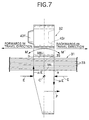
- a moment generated in a direction of an arrow M by the tangent frictional force F acts to incline the metal elements 32 forwards in the travel direction about a swinging center C.
- a radial frictional force ⁇ E generated by the urging force E between the metal elements 32 generates a moment in a direction of an arrow M' on the metal elements 32. This moment acts to incline the metal elements 32 rearwards in the travel direction about the swinging center C.
- the tangent frictional force F received by the metal elements 32 from the pulleys 6 and 11 is large at the exit portions of the drive pulley 6 and the driven pulley 11 as shown in Fig.9A, and its value reaches four times a value provided when it is supposed that the tangent frictional force F has been averagely distributed over the entire wound regions of the pulleys 6 and 11.
- the urging force between the metal elements 32 has a larger value at the exit portion of the drive pulley 6, but assumes 0 (zero) at the exit portion of the driven pulley 11.
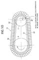
- the metal elements 32 are liable to be inclined forwards in the travel direction to the largest extent at a location where the tangent frictional force F inclining the metal element 32 forwards in the travel direction is largest and the urging force E inhibiting the forward inclination of the metal element 32 in the travel direction is 0 (zero), i.e., at the exit portion of the driven pulley 11 (see Fig.10).
- the longitudinal shapes of the saddle face of the metal element are formed asymmetrically in such a manner that the rear portion of the saddle face in the travel direction is lower in height level than the front portion in the travel direction, for the purpose of preventing the inclination of the metal element in the longitudinal direction by a pitching moment.
- These belts suffer from a problem of an increase in processing cost for the metal element, because the shape of the saddle face is complicated.
- the belts described in the above Japanese Patent Publication Nos. 2-19338 and 7-12177, and Japanese Patent Publication No. 2,617,784 are for suppressing a rolling of the metal elements, and cannot solve the problem of wear in the metal ring assemblies due to a pitching of the metal elements.
- the present invention has been accomplished with the above circumstance in view, and it is an object of the present invention to prevent the wear of the metal ring assembly due to the inclination of the metal element without increasing of the processing cost for the metal element.
- a belt for a continuously variable transmission which is wound around a drive pulley and a driven pulley for transmitting a driving force between both the pulleys
- the belt comprising a metal ring assembly formed of a plurality of endless metal rings laminated one on another, and a large number of metal elements each having a ring slot into which the metal ring assembly is fitted, wherein an endless resilient member which is deformable radially is disposed between a radially outer edge of the ring slot in the metal element and a radially outer peripheral surface of the metal ring assembly.
- the endless resilient member which is deformable radially is disposed between the radially outer edge of the ring slot in the metal element and the radially outer peripheral surface of the metal ring assembly. Therefore, when the metal elements are inclined in such a manner that they are fallen forwards in the vicinity of an exit portion of the driven pulley of the metal belt type continuously variable transmission, the metal ring assembly can be prevented from strongly interfering with the radially outer and inner edges of the ring slot in the metal ring assembly by a buffering action provided when the resilient member is deformed radially, thereby preventing wear of the metal belt to enhance the durability thereof.
- the belt is of a simple structure in which the resilient member is only added without subjecting the metal element to a special processing, and hence, the belt can be realized at an extremely low cost.
- the peripheral length of the radially inner peripheral surface of the resilient member is set longer than that of the radially outer peripheral surface of the metal ring assembly.
- the peripheral length of the radially inner peripheral surface of the resilient member is longer than that of the radially outer peripheral surface of the metal ring assembly, and hence, a clearance can be created between the resilient member and the metal ring assembly, to thereby further increase the buffering action of the resilient member.
- Figs.1 to 7 shows a first embodiment of the present invention.
- Fig.1 schematically shows the structure of a metal belt type continuously variable transmission T mounted on an automobile.
- An input shaft 3 connected to a crankshaft 1 of an engine E through a damper 2 is connected to a driving shaft 5 of the metal belt type continuously variable transmission T through a starting clutch 4.
- a drive pulley 6 provided on the driving shaft 5 comprises a stationary pulley half 7 secured to the driving shaft 5, and a movable pulley half 8 capable of moving toward and away from the stationary pulley half 7.
- the movable pulley half 8 is forced toward the stationary pulley half 7 by a hydraulic pressure applied to an oil chamber 9.
- a driven pulley 11 is provided on a driven shaft 10 disposed in parallel to the driving shaft 5, and comprises a stationary pulley half 12 secured to the driven shaft 10, and a movable pulley half 13 capable of moving toward and away from the stationary pulley half 12.
- the movable pulley half 13 is forced toward the stationary pulley half 12 by a hydraulic pressure applied to an oil chamber 14.
- a metal belt 15 is wound around the drive pulley 6 and the driven pulley 11, and comprises a large number of metal elements 32 supported on a pair of left and right metal ring assemblies 31, 31 (see Fig.2).
- Each of the metal ring assemblies 31, 31 comprises, for example, 12 metal rings 33 which are laminated on one another.
- a forward drive gear 16 and a backward drive gear 17 are relatively rotatably supported on the driven shaft 10.
- the forward drive gear 16 and the backward drive gear 17 can be coupled selectively to the driven shaft 10 by a selector 18.
- a forward driven gear 20 meshed with the forward drive gear 16 and a backward driven gear 22 meshed with the backward drive gear 17 through a backward idling gear 21 are secured to an output shaft 19 which is disposed in parallel to the driven shaft 10.
- the rotation of the output shaft 19 is input to a differential 25 through a final drive gear 23 and a final driven gear 24, and is transmitted therefrom through left and right axles 26, 26 to driven wheels W, W.
- a driving force of the engine E is transmitted to the driven shaft 10 through the crankshaft 1, the damper 2, the input shaft 3, the start clutch 4, the drive shaft 5, the driven pulley 6, the metal belt 15 and the driven pulley 11.
- the driving force of the driven shaft 10 is transmitted to the output shaft 19 through the forward drive gear 16 and the forward driven gear 20, thereby allowing the vehicle to travel forwards.
- the driving force of the driven shaft 10 is transmitted to the output shaft 19 through the backward drive gear 17, the backward idling gear 21 and the backward driven gear 22, thereby allowing the vehicle to travel backwards.
- this metal belt type continuously variable transmission T hydraulic pressures applied to the oil chamber 9 of the drive pulley 6 and the oil chamber 14 of the driven pulley 11 are controlled by a hydraulic pressure control unit U2 which is operated by a command from an electronic control unit U1, thereby continuously adjusting the change gear ratio. Specifically, if a hydraulic pressure applied to the oil chamber 14 of the driven pulley 11 is increased relative to a hydraulic pressure applied to the oil chamber 9 of the drive pulley 6, the grove width of the driven pulley 11 is reduced, leading to an increased effective radius, and correspondingly, the groove width of the drive pulley 6 is increased, leading to a reduced effective radius. Therefore, the change gear ratio of the metal belt type continuous variable transmission T is continuously varied toward "LOW".
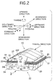
- each of the metal elements 32 formed from a metal plate by punching includes a substantially trapezoidal element body 34, a neck 36 located between a pair of left and right ring slots 35, 35 into which the metal ring assemblies 31, 31 are fitted, and a substantially triangular ear 37 connected to an upper portion of the element body 34 through the neck 36.
- the metal ring assemblies 31, 31 are sandwiched between saddle faces 38L, 38L constituting radially inner edges of the ring slots 35, 35 and lower faces 38U, 38U of the ear constituting radially outer edges of the ring slots 35, 35.
- the innermost metal rings 33, 33 of the metal ring assemblies 31, 31 are supported on the saddle faces 38L, 38L, and clearances are defined between the outermost metal rings 33, 33 of the metal ring assemblies 31, 31 and the lower faces 38U, 38U of the ear.
- Retainers 44, 44 formed into an endless band-shape from an resilient material are disposed in the clearances.
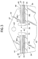
- the peripheral length of an inner surface of each of the retainers 44, 44 is set larger than that of an outer surface of each of the outermost metal rings 33, 33 and hence, a clearance ⁇ is defined between each of the retainers 44 and each of the outermost metal rings 33, 33 (see Fig.3).
- a clearance ⁇ is also defined between each of the retainers 44, 44 and each of the lower faces 38U, 38U of the ear (see Fig.3).
- the clearance ⁇ is set at 0.10 mm, and the clearance ⁇ is set at 0.05 mm. Setting the clearance ⁇ smaller than the clearance ⁇ ensures that the clearances can be defined between the outermost metal rings 33, 33 and the retainers 44, 44 over the entire peripheries of the metal belt assemblies, thereby providing a buffering effect.
- Each of the metal ring assemblies 31, 31 comprises a laminate of eleven metal rings 33, and each of the retainers 44, 44 comprises two metal rings 45, 45 longer than the peripheral length of the outer surface of the outermost metal ring 33.
- the retainer 44 constitutes a resilient member of the present invention.
- a pair of pulley-abutment faces 39, 39 are formed at laterally opposite ends of the element body 34 and capable of abutting against V-faces of the drive pulley 6 and the driven pulley 11.
- Formed on the front and rear portions of the metal element 32 is a pair of front and rear main surfaces 40, 40 which are perpendicular to the travel direction and parallel to each other.
- An inclined face 42 is formed below the front main surface 40 with a laterally extending locking edge 41 located therebetween.
- a projection 43f and a recess 43r are formed on the front and rear surfaces of the ear 37 for connecting the metal elements 32, 32 in the forward and backward directions
- the metal elements 32 are inclined in such a manner that they are fallen forwards.
- the conventional metal belt 15 having no retainers 44, 44 there is a possibility that rear ends a of the saddle faces 38L, 38L of the ring slots 35, 35 in the metal element 32 and front ends b of the lower faces 38U, 38U of the ear as viewed in the travel direction strongly abut against the inner and outer peripheral surfaces of the metal ring assemblies 31, 31, respectively, as shown in Fig.8, and the metal rings 33 are worn by a stress ⁇ H generated at such abutment portions (see Fig.8).
- the outer peripheral surfaces of the metal ring assemblies 31, 31 are put into contact with the front ends b of the lower faces 38U, 38U of the ear via the retainers 44, 44, as shown in Fig. 4, and the retainers 44, 44 can be resiliently deformed to absorb a shock (see Fig.4), because the clearances ⁇ and ⁇ exist radially inside and outside the retainers 44, 44.
- the metal element 32 can be smoothly meshed with the drive pulley 6, thereby inhibiting the generation of the abnormal wear and noise, to enhance the durability of the metal element 32 and the drive pulley 6.
- the flexural rigidity of the retainers 44, 44 is set lower than that of the metal ring assemblies 31, 31 so that there is no influence on the efficiency.
- the retainer 44 in the first embodiment comprises the laminate of the two metal rings 45, 45, but a retainer 44 in the second embodiment comprises a single metal ring.
- the thickness of a material can be set as desired according to the resilience performance of the metal ring.
- the thickness of the metal ring of the retainer 44 in the present embodiment is larger than that of the metal ring 33 of the metal ring assembly 31, but the metal ring of the retainer 44 in the present embodiment may be formed to have a thickness smaller than that of the metal ring 33 by using a material having a higher rigidity.
- a retainer 44 in the third embodiment also comprises a single metal ring, but has a widthwise-central portion curved radially outwards in a convex shape. This curved portion can exert a shock-absorbing function to achieve an effect similar to that in each of the first and second embodiments.
- the retainer 44 may be in contact with the metal ring assembly 31 and the lower face 38U of the ear.
- the endless resilient member which is deformable radially is disposed between the radially outer edge of the ring slot in the metal element and the radially outer peripheral surface of the metal ring assembly. Therefore, when the metal elements are inclined in such a manner that they are fallen forwards in the vicinity of an exit portion of the driven pulley of the metal belt-type continuously variable transmission, the metal element can be prevented from strongly interfering with the radially outer and inner edges of the ring slot in the metal ring assembly by a buffering action provided when the resilient member is deformed radially, thereby preventing the wear of the metal belt to enhance the durability thereof.
- the belt is of a simple structure in which the resilient member is only added without subjecting the metal element to a special processing, and hence, the belt can be realized at an extremely low cost.
- the peripheral length of the radially inner peripheral surface of the resilient member is longer than that of the radially outer peripheral surface of the metal ring assembly, and hence, a clearance can be created between the resilient member and the metal ring assembly, to thereby further increase the buffering action of the resilient member.
- a metal belt for a continuously variable transmission includes many metal elements assembled to an endless metal ring assembly, and is wound around drive and driven pulleys to transmit a driving force.
- a retainer comprising an endless resilient member deformable radially is disposed between a lower face of an ear of a ring slot in the metal element and a radially outer peripheral surface of the metal ring assembly.
Landscapes
- Engineering & Computer Science (AREA)
- General Engineering & Computer Science (AREA)
- Mechanical Engineering (AREA)
- Transmissions By Endless Flexible Members (AREA)
Abstract
Description
- The present invention relates to a belt for a continuously variable transmission, which is wound around a drive pulley and a driven pulley for transmitting a driving force between both the pulleys, and which comprises a metal ring assembly formed of a plurality of endless metal rings laminated one on another, and a large number of metal elements each having a ring slot into which the metal ring assembly is fitted.
- As shown in Fig.8, the
metal elements 32 are supported on themetal ring assemblies ring slots metal elements 32 are inclined forwards in a travel direction, rear ends a ofsaddle faces metal ring assemblies lower faces metal ring assemblies metal elements 32 in the travel direction is caused by a tangent frictional force F received by themetal elements 32 at their contact faces with the pulleys, and an urging force between themetal elements 32, and is particularly significant at an exit portion of the driven pulley. The reason will be described below. - As can be seen from Fig.7, a moment generated in a direction of an arrow M by the tangent frictional force F acts to incline the
metal elements 32 forwards in the travel direction about a swinging center C. On the other hand, a radial frictional force µE generated by the urging force E between themetal elements 32 generates a moment in a direction of an arrow M' on themetal elements 32. This moment acts to incline themetal elements 32 rearwards in the travel direction about the swinging center C. - It is known that the tangent frictional force F received by the
metal elements 32 from thepulleys drive pulley 6 and the drivenpulley 11 as shown in Fig.9A, and its value reaches four times a value provided when it is supposed that the tangent frictional force F has been averagely distributed over the entire wound regions of thepulleys metal elements 32 has a larger value at the exit portion of thedrive pulley 6, but assumes 0 (zero) at the exit portion of the drivenpulley 11. Therefore, themetal elements 32 are liable to be inclined forwards in the travel direction to the largest extent at a location where the tangent frictional force F inclining themetal element 32 forwards in the travel direction is largest and the urging force E inhibiting the forward inclination of themetal element 32 in the travel direction is 0 (zero), i.e., at the exit portion of the driven pulley 11 (see Fig.10). - For this reason, when the
metal elements 32 are inclined largely forwards in the travel direction at the exit portion of the drivenpulley 11, the following problem is encountered: The rear ends a of the saddle faces 38L, 38L of themetal element 32 and the front ends b of thelower faces metal ring assembly 31, respectively (see Fig.8) and as a result, the metal ring assemblies 31, 31 are worn by a stress σH generated at such abutment portions. - There are conventionally known metal elements which are described in Japanese Utility Model Application Laid-open Nos. 59-79653 and 63-17353, Japanese Patent Application Laid-open No. 6-10993 and Japanese Utility Model Application Laid-open No. 60-107444, and which have a feature in shape of a saddle face against which an inner peripheral surface of a metal ring assembly abuts.
- Belts designed so that the rolling of a metal element is inhibited to enhance the durability of a metal ring assembly, are conventionally known from Japanese Patent Publication No. 2-19338, Japanese Patent Application Laid-open No. 7-12177 and Japanese Patent Publication No. 2,617,784.
- In the belt described in Japanese Utility Model Application Laid-open No.59-79653, opposite edges of a saddle face of the metal element in a travel direction are smoothly chamfered. In the belt described in Japanese Utility Model Application Laid-open No.63-17353, a stepped protrusion is formed at a central portion in a travel direction of the saddle face of the metal element, and an arcuate face having a radius equal to a minimum winding radius of the metal ring assembly is formed on top of the protrusion. The purpose of this arrangement is not described clearly in the specification, but it seems that the purpose is to alleviate the strong abutment between the opposite ends of the saddle face in the travel direction and the inner peripheral surface of the metal ring assembly at the portions of the belt for continuously variable transmission which are wound around the pulleys . In these belts , the shapes of the saddle faces are symmetrical longitudinally in the travel direction and for this reason, it is difficult to effectively alleviate the Hertz's stress generated by the abutment between the opposite ends of the saddle face in the travel direction and the inner peripheral surface of the metal ring assembly.
- In the belts described in Japanese Patent Application Laid-open No.6-10993 and Japanese Utility Model Application Laid-open No.60-107444, the longitudinal shapes of the saddle face of the metal element are formed asymmetrically in such a manner that the rear portion of the saddle face in the travel direction is lower in height level than the front portion in the travel direction, for the purpose of preventing the inclination of the metal element in the longitudinal direction by a pitching moment. These belts suffer from a problem of an increase in processing cost for the metal element, because the shape of the saddle face is complicated.
- The belts described in the above Japanese Patent Publication Nos. 2-19338 and 7-12177, and Japanese Patent Publication No. 2,617,784 are for suppressing a rolling of the metal elements, and cannot solve the problem of wear in the metal ring assemblies due to a pitching of the metal elements.
- The present invention has been accomplished with the above circumstance in view, and it is an object of the present invention to prevent the wear of the metal ring assembly due to the inclination of the metal element without increasing of the processing cost for the metal element.
- To achieve the above object, according to a first feature of the present invention, there is provided a belt for a continuously variable transmission, which is wound around a drive pulley and a driven pulley for transmitting a driving force between both the pulleys, the belt comprising a metal ring assembly formed of a plurality of endless metal rings laminated one on another, and a large number of metal elements each having a ring slot into which the metal ring assembly is fitted, wherein an endless resilient member which is deformable radially is disposed between a radially outer edge of the ring slot in the metal element and a radially outer peripheral surface of the metal ring assembly.
- With the above arrangement, the endless resilient member which is deformable radially is disposed between the radially outer edge of the ring slot in the metal element and the radially outer peripheral surface of the metal ring assembly. Therefore, when the metal elements are inclined in such a manner that they are fallen forwards in the vicinity of an exit portion of the driven pulley of the metal belt type continuously variable transmission, the metal ring assembly can be prevented from strongly interfering with the radially outer and inner edges of the ring slot in the metal ring assembly by a buffering action provided when the resilient member is deformed radially, thereby preventing wear of the metal belt to enhance the durability thereof. Moreover, the belt is of a simple structure in which the resilient member is only added without subjecting the metal element to a special processing, and hence, the belt can be realized at an extremely low cost.
- According to a second feature of the present invention, the peripheral length of the radially inner peripheral surface of the resilient member is set longer than that of the radially outer peripheral surface of the metal ring assembly.
- With the above arrangement, the peripheral length of the radially inner peripheral surface of the resilient member is longer than that of the radially outer peripheral surface of the metal ring assembly, and hence, a clearance can be created between the resilient member and the metal ring assembly, to thereby further increase the buffering action of the resilient member.
-
- Fig.1 is a skeleton illustration of a power transmitting system for a vehicle equipped with a continuously variable transmission.
- Fig.2 is a partial perspective view of a metal belt.
- Fig. 3 is an enlarged view taken in a direction of an
arrow 3 in Fig.2. - Fig.4 is a diagram for explaining the shock-absorbing action of a retainer.
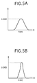
- Figs.5A and 5B are graphs for explaining the shock-absorbing performance of the retainer.
- Figs.6A and 6B are views for explaining a function by the retainer for inhibiting the rolling of a metal element.
- Fig.7 is a side view of the metal element in an upright state.
- Fig.8 is a side view of the metal element in an inclined state.
- Fig.9A and 9B are a diagram showing the distribution of a tangent frictional force F received by the metal element from a pulley and the distribution of an urging force E between the metal elements.
- Fig.10 is an illustration showing the inclination of the metal elements in the vicinity of an exit portion of a driven pulley.
- Fig.11 is a view similar to Fig.3, but according to a second embodiment of the present invention.
- Fig. 12 is a view similar to Fig.3, but according to a third embodiment of the present invention.
-
- The mode for carrying out the present invention will now be described by way of embodiments of the present invention shown in the accompanying drawings.
- Figs.1 to 7 shows a first embodiment of the present invention.
- Fig.1 schematically shows the structure of a metal belt type continuously variable transmission T mounted on an automobile. An
input shaft 3 connected to a crankshaft 1 of an engine E through adamper 2 is connected to adriving shaft 5 of the metal belt type continuously variable transmission T through a startingclutch 4. Adrive pulley 6 provided on thedriving shaft 5 comprises a stationary pulley half 7 secured to thedriving shaft 5, and amovable pulley half 8 capable of moving toward and away from the stationary pulley half 7. Themovable pulley half 8 is forced toward the stationary pulley half 7 by a hydraulic pressure applied to anoil chamber 9. - A driven
pulley 11 is provided on a drivenshaft 10 disposed in parallel to thedriving shaft 5, and comprises astationary pulley half 12 secured to the drivenshaft 10, and amovable pulley half 13 capable of moving toward and away from thestationary pulley half 12. Themovable pulley half 13 is forced toward thestationary pulley half 12 by a hydraulic pressure applied to anoil chamber 14. Ametal belt 15 is wound around thedrive pulley 6 and the drivenpulley 11, and comprises a large number ofmetal elements 32 supported on a pair of left and rightmetal ring assemblies 31, 31 (see Fig.2). Each of the metal ring assemblies 31, 31 comprises, for example, 12metal rings 33 which are laminated on one another. - A
forward drive gear 16 and a backwarddrive gear 17 are relatively rotatably supported on the drivenshaft 10. Theforward drive gear 16 and the backwarddrive gear 17 can be coupled selectively to the drivenshaft 10 by aselector 18. A forward drivengear 20 meshed with theforward drive gear 16 and a backward drivengear 22 meshed with the backwarddrive gear 17 through a backwardidling gear 21 are secured to anoutput shaft 19 which is disposed in parallel to the drivenshaft 10. - The rotation of the
output shaft 19 is input to adifferential 25 through afinal drive gear 23 and a final drivengear 24, and is transmitted therefrom through left andright axles - A driving force of the engine E is transmitted to the driven
shaft 10 through the crankshaft 1, thedamper 2, theinput shaft 3, thestart clutch 4, thedrive shaft 5, the drivenpulley 6, themetal belt 15 and the drivenpulley 11. When a forward travel range is selected, the driving force of the drivenshaft 10 is transmitted to theoutput shaft 19 through theforward drive gear 16 and the forward drivengear 20, thereby allowing the vehicle to travel forwards. When a backward travel range is selected, the driving force of the drivenshaft 10 is transmitted to theoutput shaft 19 through the backwarddrive gear 17, the backwardidling gear 21 and the backward drivengear 22, thereby allowing the vehicle to travel backwards. - In this metal belt type continuously variable transmission T, hydraulic pressures applied to the
oil chamber 9 of thedrive pulley 6 and theoil chamber 14 of the drivenpulley 11 are controlled by a hydraulic pressure control unit U2 which is operated by a command from an electronic control unit U1, thereby continuously adjusting the change gear ratio. Specifically, if a hydraulic pressure applied to theoil chamber 14 of the drivenpulley 11 is increased relative to a hydraulic pressure applied to theoil chamber 9 of thedrive pulley 6, the grove width of the drivenpulley 11 is reduced, leading to an increased effective radius, and correspondingly, the groove width of thedrive pulley 6 is increased, leading to a reduced effective radius. Therefore, the change gear ratio of the metal belt type continuous variable transmission T is continuously varied toward "LOW". On the other hand, if the hydraulic pressure applied to theoil chamber 9 of thedrive pulley 6 is increased relative to the hydraulic pressure applied to theoil chamber 14 of the drivenpulley 11, the groove width of thedrive pulley 6 is reduced, leading to an increased effective radius, and correspondingly, the groove width of the drivenpulley 11 is increased, leading to a reduced effective radius . Therefore, the change gear ratio of the metal belt type continuous variable transmission T is continuously varied toward "TOP". - As shown in Fig.2, each of the
metal elements 32 formed from a metal plate by punching, includes a substantiallytrapezoidal element body 34, aneck 36 located between a pair of left andright ring slots metal ring assemblies triangular ear 37 connected to an upper portion of theelement body 34 through theneck 36. Themetal ring assemblies ring slots lower faces ring slots metal ring assemblies metal ring assemblies Retainers retainers retainers 44 and each of the outermost metal rings 33, 33 (see Fig.3). A clearance β is also defined between each of theretainers retainers - Each of the
metal ring assemblies retainers outermost metal ring 33. Theretainer 44 constitutes a resilient member of the present invention. - A pair of pulley-abutment faces 39, 39 are formed at laterally opposite ends of the
element body 34 and capable of abutting against V-faces of thedrive pulley 6 and the drivenpulley 11. Formed on the front and rear portions of themetal element 32 is a pair of front and rearmain surfaces inclined face 42 is formed below the frontmain surface 40 with a laterally extending lockingedge 41 located therebetween. Further, formed on the front and rear surfaces of theear 37 are aprojection 43f and arecess 43r (see Fig.4) for connecting themetal elements - As already described with reference to Figs.7 to 10, in the vicinity of an exit of the driven
pulley 11 of the metal belt type continuously variable transmission T, themetal elements 32 are inclined in such a manner that they are fallen forwards. In this case, in theconventional metal belt 15 having noretainers ring slots metal element 32 and front ends b of the lower faces 38U, 38U of the ear as viewed in the travel direction strongly abut against the inner and outer peripheral surfaces of themetal ring assemblies metal ring assemblies retainers retainers retainers - As described above, when the shock acting on the front ends b of the lower faces 38U, 38U of the ear as viewed in the travel direction by the resilient deformation of the
retainers metal belt 15 can be prevented by a simple structure in which the tworetainers metal elements 32 to a special processing. - If there is a rolling of the
metal element 32 generated when themetal element 32 is meshed with thedrive pulley 6, the following problem is encountered: The pulley-abutment faces 39, 39 of themetal element 32 cannot be smoothly engaged with the V-faces of thedrive pulley 6, thereby generating an abnormal wear and/or noise. However, the rolling of themetal element 32 is inhibited by the shock absorbing effect provided by mounting theretainers 44, 44 (see Fig.6A), because the clearances between theretainers metal element 32 can be smoothly meshed with thedrive pulley 6, thereby inhibiting the generation of the abnormal wear and noise, to enhance the durability of themetal element 32 and thedrive pulley 6. The flexural rigidity of theretainers metal ring assemblies - A second embodiment of the present invention will now be described with reference to Fig.11.
- The
retainer 44 in the first embodiment comprises the laminate of the two metal rings 45, 45, but aretainer 44 in the second embodiment comprises a single metal ring. In this case, the thickness of a material can be set as desired according to the resilience performance of the metal ring. The thickness of the metal ring of theretainer 44 in the present embodiment is larger than that of themetal ring 33 of themetal ring assembly 31, but the metal ring of theretainer 44 in the present embodiment may be formed to have a thickness smaller than that of themetal ring 33 by using a material having a higher rigidity. - A third embodiment of the present invention will be described below with reference to Fig.12.
- A
retainer 44 in the third embodiment also comprises a single metal ring, but has a widthwise-central portion curved radially outwards in a convex shape. This curved portion can exert a shock-absorbing function to achieve an effect similar to that in each of the first and second embodiments. In this case, theretainer 44 may be in contact with themetal ring assembly 31 and thelower face 38U of the ear. - As discussed above, according to the first feature of the present invention, the endless resilient member which is deformable radially is disposed between the radially outer edge of the ring slot in the metal element and the radially outer peripheral surface of the metal ring assembly. Therefore, when the metal elements are inclined in such a manner that they are fallen forwards in the vicinity of an exit portion of the driven pulley of the metal belt-type continuously variable transmission, the metal element can be prevented from strongly interfering with the radially outer and inner edges of the ring slot in the metal ring assembly by a buffering action provided when the resilient member is deformed radially, thereby preventing the wear of the metal belt to enhance the durability thereof. Moreover, the belt is of a simple structure in which the resilient member is only added without subjecting the metal element to a special processing, and hence, the belt can be realized at an extremely low cost.
- According to the second feature of the present invention, the peripheral length of the radially inner peripheral surface of the resilient member is longer than that of the radially outer peripheral surface of the metal ring assembly, and hence, a clearance can be created between the resilient member and the metal ring assembly, to thereby further increase the buffering action of the resilient member.
- Although the embodiments of the present invention have been described in detail, it will be understood that various modifications in design may be made without departing from the subject matter of the invention.
- A metal belt for a continuously variable transmission includes many metal elements assembled to an endless metal ring assembly, and is wound around drive and driven pulleys to transmit a driving force. A retainer comprising an endless resilient member deformable radially is disposed between a lower face of an ear of a ring slot in the metal element and a radially outer peripheral surface of the metal ring assembly. When the metal elements are inclined in such a manner that they are fallen forwards in the vicinity of an exit portion of the driven pulley, the metal ring assembly is prevented from strongly interfering with a lower face of the ear and a saddle face by a buffering action provided when the retainer is deformed radially, thereby preventing the wear of the metal belt to enhance its durability without increasing the processing cost for the metal elements.
Claims (2)
- A belt for a continuously variable transmission, which is wound around a drive pulley and a driven pulley for transmitting a driving force between both the pulleys, the belt comprising a metal ring assembly formed of a plurality of endless metal rings laminated one on another, and a large number of metal elements each having a ring slot into which the metal ring assembly is fitted, wherein
an endless resilient member which is deformable radially is disposed between a radially outer edge of the ring slot in the metal element and a radially outer peripheral surface of the metal ring assembly. - A belt for a continuously variable transmission according to claim 1, wherein the peripheral length of the radially inner peripheral surface of the resilient member is set longer than that of the radially outer peripheral surface of the metal ring assembly.
Applications Claiming Priority (2)
| Application Number | Priority Date | Filing Date | Title |
|---|---|---|---|
| JP2000238184 | 2000-08-07 | ||
| JP2000238184A JP2002054690A (en) | 2000-08-07 | 2000-08-07 | Belt for continuously variable transmission |
Publications (3)
| Publication Number | Publication Date |
|---|---|
| EP1179689A1 true EP1179689A1 (en) | 2002-02-13 |
| EP1179689B1 EP1179689B1 (en) | 2006-03-08 |
| EP1179689B8 EP1179689B8 (en) | 2007-01-24 |
Family
ID=18729927
Family Applications (1)
| Application Number | Title | Priority Date | Filing Date |
|---|---|---|---|
| EP01119002A Expired - Lifetime EP1179689B8 (en) | 2000-08-07 | 2001-08-06 | Belt for continuously variable transmission |
Country Status (4)
| Country | Link |
|---|---|
| US (1) | US7077775B2 (en) |
| EP (1) | EP1179689B8 (en) |
| JP (1) | JP2002054690A (en) |
| DE (1) | DE60117647T8 (en) |
Cited By (1)
| Publication number | Priority date | Publication date | Assignee | Title |
|---|---|---|---|---|
| WO2006068462A1 (en) * | 2004-12-24 | 2006-06-29 | Robert Bosch Gmbh | Method for manufacturing push belts of distinguishable type and a composition of push belt types |
Families Citing this family (9)
| Publication number | Priority date | Publication date | Assignee | Title |
|---|---|---|---|---|
| JP2014141976A (en) * | 2011-03-28 | 2014-08-07 | Jatco Ltd | Element and belt of belt-type continuously variable transmission |
| DE112012006666T5 (en) * | 2012-07-06 | 2015-03-19 | Honda Motor Co., Ltd. | Element for metallic belt |
| JP6506062B2 (en) * | 2015-03-24 | 2019-04-24 | 本田技研工業株式会社 | Method of manufacturing metal element for continuously variable transmission |
| JP6444355B2 (en) * | 2016-11-04 | 2018-12-26 | 本田技研工業株式会社 | Metal element for continuously variable transmission and method for manufacturing metal element for continuously variable transmission |
| NL1042192B1 (en) * | 2016-12-22 | 2018-06-29 | Bosch Gmbh Robert | A drive belt for a continuously variable transmission with transverse segments and a ring stack and its manufacutring method |
| US11149820B2 (en) * | 2017-03-03 | 2021-10-19 | Aisin Aw Co., Ltd. | Element designing method and power transfer belt |
| JP6747377B2 (en) * | 2017-05-16 | 2020-08-26 | アイシン・エィ・ダブリュ株式会社 | Continuously variable transmission and transmission belt |
| JP6523381B2 (en) * | 2017-07-28 | 2019-05-29 | 本田技研工業株式会社 | Method of manufacturing metal element for continuously variable transmission |
| JP2020070809A (en) * | 2018-10-29 | 2020-05-07 | トヨタ自動車株式会社 | Transmission belt |
Citations (12)
| Publication number | Priority date | Publication date | Assignee | Title |
|---|---|---|---|---|
| DE2414989A1 (en) * | 1974-03-28 | 1975-10-09 | Heynau Gmbh Hans | Link V-belt with trapezoidal links - have slots to engage with traction element with no free play |
| JPS5979653A (en) | 1982-10-27 | 1984-05-08 | Fujitsu Ltd | Majority decision circuit |
| US4498892A (en) * | 1983-03-14 | 1985-02-12 | Borg-Warner Corporation | Power transmission belt |
| JPS60107444A (en) | 1983-11-12 | 1985-06-12 | Nissin Kogyo Kk | Hydraulic booster for tandem type master cylinder |
| EP0151396A2 (en) * | 1984-01-24 | 1985-08-14 | Van Doorne's Transmissie B.V. | Driving belts for use on V-belt pulleys |
| JPH0219338A (en) | 1988-06-29 | 1990-01-23 | Century Lab Inc | Extraction and purification of poly (unsaturated fatty acid) from natural source |
| EP0367620A1 (en) * | 1988-11-04 | 1990-05-09 | Fuji Jukogyo Kabushiki Kaisha | Belt for a continously variable transmission |
| EP0510990A2 (en) * | 1991-04-25 | 1992-10-28 | Matsumoto Sangyo Kabushiki Kaisha | Driving belt for stepless speed variation |
| EP0562654A1 (en) * | 1992-03-24 | 1993-09-29 | Van Doorne's Transmissie B.V. | Transverse element for a drive belt |
| JPH06317353A (en) | 1993-05-07 | 1994-11-15 | Sekisui Chem Co Ltd | Electric water heater |
| EP0626526A1 (en) * | 1993-05-24 | 1994-11-30 | Van Doorne's Transmissie B.V. | Drive belt |
| JP2617784B2 (en) * | 1988-11-04 | 1997-06-04 | 富士重工業株式会社 | Belt for continuously variable transmission |
Family Cites Families (9)
| Publication number | Priority date | Publication date | Assignee | Title |
|---|---|---|---|---|
| DE2414891C3 (en) * | 1974-03-28 | 1982-09-23 | Hans Heynau GmbH, 8000 München | Link belt |
| DE2557724B2 (en) * | 1975-12-20 | 1978-10-12 | Hans Heynau Gmbh, 8000 Muenchen | Link V-belt |
| IT1197513B (en) * | 1979-10-26 | 1988-11-30 | S I R A Societe Ind Ricerche A | METAL BELT FOR POWER TRANSMISSION |
| JPS59197641A (en) * | 1983-04-23 | 1984-11-09 | Honda Motor Co Ltd | V-belt transmission device |
| JPS5950252A (en) * | 1983-07-18 | 1984-03-23 | Honda Motor Co Ltd | V belt transmission device |
| FR2625783B1 (en) * | 1988-01-11 | 1990-05-11 | Caoutchouc Manuf Plastique | TRANSMISSION MEMBER FOR CONTINUOUS SPEED VARIATOR, WITH PUSHING CROSS LINKS AND FLEXIBLE CORE, OPERATING BY DRY FRICTION |
| JPH0723643Y2 (en) * | 1989-11-16 | 1995-05-31 | 本田技研工業株式会社 | Metal V belt |
| JP3524766B2 (en) * | 1998-06-08 | 2004-05-10 | 本田技研工業株式会社 | Metal V belt |
| EP1132649B1 (en) * | 1998-11-05 | 2005-02-02 | Fukuju Kogyo Kabushiki Kaisha | Metal belt element |
-
2000
- 2000-08-07 JP JP2000238184A patent/JP2002054690A/en active Pending
-
2001
- 2001-08-06 DE DE60117647T patent/DE60117647T8/en not_active Expired - Fee Related
- 2001-08-06 US US09/921,996 patent/US7077775B2/en not_active Expired - Fee Related
- 2001-08-06 EP EP01119002A patent/EP1179689B8/en not_active Expired - Lifetime
Patent Citations (15)
| Publication number | Priority date | Publication date | Assignee | Title |
|---|---|---|---|---|
| DE2414989A1 (en) * | 1974-03-28 | 1975-10-09 | Heynau Gmbh Hans | Link V-belt with trapezoidal links - have slots to engage with traction element with no free play |
| JPS5979653A (en) | 1982-10-27 | 1984-05-08 | Fujitsu Ltd | Majority decision circuit |
| US4498892A (en) * | 1983-03-14 | 1985-02-12 | Borg-Warner Corporation | Power transmission belt |
| JPS60107444A (en) | 1983-11-12 | 1985-06-12 | Nissin Kogyo Kk | Hydraulic booster for tandem type master cylinder |
| JPH0219338B2 (en) * | 1984-01-24 | 1990-05-01 | Doornes Transmissie Bv | |
| EP0151396A2 (en) * | 1984-01-24 | 1985-08-14 | Van Doorne's Transmissie B.V. | Driving belts for use on V-belt pulleys |
| JPH0219338A (en) | 1988-06-29 | 1990-01-23 | Century Lab Inc | Extraction and purification of poly (unsaturated fatty acid) from natural source |
| EP0367620A1 (en) * | 1988-11-04 | 1990-05-09 | Fuji Jukogyo Kabushiki Kaisha | Belt for a continously variable transmission |
| JP2617784B2 (en) * | 1988-11-04 | 1997-06-04 | 富士重工業株式会社 | Belt for continuously variable transmission |
| EP0510990A2 (en) * | 1991-04-25 | 1992-10-28 | Matsumoto Sangyo Kabushiki Kaisha | Driving belt for stepless speed variation |
| EP0562654A1 (en) * | 1992-03-24 | 1993-09-29 | Van Doorne's Transmissie B.V. | Transverse element for a drive belt |
| JPH0610993A (en) | 1992-03-24 | 1994-01-21 | Van Doornes Transmissie Bv | Transverse member for driving belt |
| JPH06317353A (en) | 1993-05-07 | 1994-11-15 | Sekisui Chem Co Ltd | Electric water heater |
| EP0626526A1 (en) * | 1993-05-24 | 1994-11-30 | Van Doorne's Transmissie B.V. | Drive belt |
| JPH0712177A (en) | 1993-05-24 | 1995-01-17 | Van Doornes Transmissie Bv | Belt for driving |
Cited By (2)
| Publication number | Priority date | Publication date | Assignee | Title |
|---|---|---|---|---|
| WO2006068462A1 (en) * | 2004-12-24 | 2006-06-29 | Robert Bosch Gmbh | Method for manufacturing push belts of distinguishable type and a composition of push belt types |
| CN101084388B (en) * | 2004-12-24 | 2010-04-28 | 罗伯特·博世有限公司 | Push belt manufacturing method capable of distinguishing models and group product of push belt with multiple models |
Also Published As
| Publication number | Publication date |
|---|---|
| DE60117647D1 (en) | 2006-05-04 |
| EP1179689B1 (en) | 2006-03-08 |
| EP1179689B8 (en) | 2007-01-24 |
| DE60117647T2 (en) | 2006-11-23 |
| US7077775B2 (en) | 2006-07-18 |
| DE60117647T8 (en) | 2007-03-08 |
| JP2002054690A (en) | 2002-02-20 |
| US20020025872A1 (en) | 2002-02-28 |
Similar Documents
| Publication | Publication Date | Title |
|---|---|---|
| EP1061285B1 (en) | Belt for continuously variable transmission | |
| US6440025B1 (en) | Belt for continuously variable transmission | |
| EP1067311B1 (en) | Belt for continuously variable transmission | |
| EP1162387B1 (en) | Belt for non-stage transmissions | |
| EP1179690B1 (en) | Belt for continuously variable transmission | |
| CA2372245C (en) | Belt for continuously variable transmission | |
| EP1179689B1 (en) | Belt for continuously variable transmission | |
| EP1371876B1 (en) | Belt for continuously variable transmission | |
| US6409620B1 (en) | Belt for continuosly variable transmission | |
| EP1199494B1 (en) | Belt for continuously variable transmission | |
| EP1069343A1 (en) | Belt for continuously variable transmission | |
| US6270437B1 (en) | Belt for continuously variable transmission | |
| EP1566567B1 (en) | Metallic belt for stepless speed changer | |
| US6672984B2 (en) | Belt for continuously variable transmission | |
| US6336884B1 (en) | Belt for continuously variable transmission | |
| EP1179691B1 (en) | Belt for continuously variable transmission | |
| US20090118042A1 (en) | Power Transmission Chain and Power Transmission Apparatus | |
| US6626783B1 (en) | Belt for continuously variable transmission | |
| EP1283378A2 (en) | Belt for countinuously variable transmission | |
| JP2009085411A (en) | Belt for continuously variable transmission |
Legal Events
| Date | Code | Title | Description |
|---|---|---|---|
| PUAI | Public reference made under article 153(3) epc to a published international application that has entered the european phase |
Free format text: ORIGINAL CODE: 0009012 |
|
| AK | Designated contracting states |
Kind code of ref document: A1 Designated state(s): AT BE CH CY DE DK ES FI FR GB GR IE IT LI LU MC NL PT SE TR Kind code of ref document: A1 Designated state(s): DE NL |
|
| AX | Request for extension of the european patent |
Free format text: AL;LT;LV;MK;RO;SI |
|
| 17P | Request for examination filed |
Effective date: 20020405 |
|
| AKX | Designation fees paid |
Free format text: DE NL |
|
| 17Q | First examination report despatched |
Effective date: 20040727 |
|
| GRAP | Despatch of communication of intention to grant a patent |
Free format text: ORIGINAL CODE: EPIDOSNIGR1 |
|
| GRAS | Grant fee paid |
Free format text: ORIGINAL CODE: EPIDOSNIGR3 |
|
| GRAA | (expected) grant |
Free format text: ORIGINAL CODE: 0009210 |
|
| AK | Designated contracting states |
Kind code of ref document: B1 Designated state(s): DE NL |
|
| REF | Corresponds to: |
Ref document number: 60117647 Country of ref document: DE Date of ref document: 20060504 Kind code of ref document: P |
|
| PGFP | Annual fee paid to national office [announced via postgrant information from national office to epo] |
Ref country code: NL Payment date: 20060803 Year of fee payment: 6 Ref country code: DE Payment date: 20060803 Year of fee payment: 6 |
|
| RIN2 | Information on inventor provided after grant (corrected) |
Inventor name: SHIBA, TOYOMIC/O K. K. HONDA GIJUTSU KENKYUSHO |
|
| PLBE | No opposition filed within time limit |
Free format text: ORIGINAL CODE: 0009261 |
|
| STAA | Information on the status of an ep patent application or granted ep patent |
Free format text: STATUS: NO OPPOSITION FILED WITHIN TIME LIMIT |
|
| 26N | No opposition filed |
Effective date: 20061211 |
|
| PG25 | Lapsed in a contracting state [announced via postgrant information from national office to epo] |
Ref country code: NL Free format text: LAPSE BECAUSE OF NON-PAYMENT OF DUE FEES Effective date: 20080301 |
|
| NLV4 | Nl: lapsed or anulled due to non-payment of the annual fee |
Effective date: 20080301 |
|
| PG25 | Lapsed in a contracting state [announced via postgrant information from national office to epo] |
Ref country code: DE Free format text: LAPSE BECAUSE OF NON-PAYMENT OF DUE FEES Effective date: 20080301 |