EP1179382A2 - Laser beam machining head and laser beam machining apparatus having same - Google Patents
Laser beam machining head and laser beam machining apparatus having same Download PDFInfo
- Publication number
- EP1179382A2 EP1179382A2 EP01118789A EP01118789A EP1179382A2 EP 1179382 A2 EP1179382 A2 EP 1179382A2 EP 01118789 A EP01118789 A EP 01118789A EP 01118789 A EP01118789 A EP 01118789A EP 1179382 A2 EP1179382 A2 EP 1179382A2
- Authority
- EP
- European Patent Office
- Prior art keywords
- laser beam
- laser light
- divisional
- laser
- reflecting mirror
- Prior art date
- Legal status (The legal status is an assumption and is not a legal conclusion. Google has not performed a legal analysis and makes no representation as to the accuracy of the status listed.)
- Granted
Links
Images





Classifications
-
- B—PERFORMING OPERATIONS; TRANSPORTING
- B23—MACHINE TOOLS; METAL-WORKING NOT OTHERWISE PROVIDED FOR
- B23K—SOLDERING OR UNSOLDERING; WELDING; CLADDING OR PLATING BY SOLDERING OR WELDING; CUTTING BY APPLYING HEAT LOCALLY, e.g. FLAME CUTTING; WORKING BY LASER BEAM
- B23K26/00—Working by laser beam, e.g. welding, cutting or boring
- B23K26/02—Positioning or observing the workpiece, e.g. with respect to the point of impact; Aligning, aiming or focusing the laser beam
- B23K26/06—Shaping the laser beam, e.g. by masks or multi-focusing
- B23K26/0604—Shaping the laser beam, e.g. by masks or multi-focusing by a combination of beams
- B23K26/0608—Shaping the laser beam, e.g. by masks or multi-focusing by a combination of beams in the same heat affected zone [HAZ]
-
- B—PERFORMING OPERATIONS; TRANSPORTING
- B23—MACHINE TOOLS; METAL-WORKING NOT OTHERWISE PROVIDED FOR
- B23K—SOLDERING OR UNSOLDERING; WELDING; CLADDING OR PLATING BY SOLDERING OR WELDING; CUTTING BY APPLYING HEAT LOCALLY, e.g. FLAME CUTTING; WORKING BY LASER BEAM
- B23K26/00—Working by laser beam, e.g. welding, cutting or boring
- B23K26/02—Positioning or observing the workpiece, e.g. with respect to the point of impact; Aligning, aiming or focusing the laser beam
- B23K26/06—Shaping the laser beam, e.g. by masks or multi-focusing
- B23K26/0604—Shaping the laser beam, e.g. by masks or multi-focusing by a combination of beams
-
- B—PERFORMING OPERATIONS; TRANSPORTING
- B23—MACHINE TOOLS; METAL-WORKING NOT OTHERWISE PROVIDED FOR
- B23K—SOLDERING OR UNSOLDERING; WELDING; CLADDING OR PLATING BY SOLDERING OR WELDING; CUTTING BY APPLYING HEAT LOCALLY, e.g. FLAME CUTTING; WORKING BY LASER BEAM
- B23K26/00—Working by laser beam, e.g. welding, cutting or boring
- B23K26/02—Positioning or observing the workpiece, e.g. with respect to the point of impact; Aligning, aiming or focusing the laser beam
- B23K26/06—Shaping the laser beam, e.g. by masks or multi-focusing
- B23K26/067—Dividing the beam into multiple beams, e.g. multi-focusing
-
- B—PERFORMING OPERATIONS; TRANSPORTING
- B23—MACHINE TOOLS; METAL-WORKING NOT OTHERWISE PROVIDED FOR
- B23K—SOLDERING OR UNSOLDERING; WELDING; CLADDING OR PLATING BY SOLDERING OR WELDING; CUTTING BY APPLYING HEAT LOCALLY, e.g. FLAME CUTTING; WORKING BY LASER BEAM
- B23K26/00—Working by laser beam, e.g. welding, cutting or boring
- B23K26/08—Devices involving relative movement between laser beam and workpiece
- B23K26/082—Scanning systems, i.e. devices involving movement of the laser beam relative to the laser head
-
- B—PERFORMING OPERATIONS; TRANSPORTING
- B23—MACHINE TOOLS; METAL-WORKING NOT OTHERWISE PROVIDED FOR
- B23K—SOLDERING OR UNSOLDERING; WELDING; CLADDING OR PLATING BY SOLDERING OR WELDING; CUTTING BY APPLYING HEAT LOCALLY, e.g. FLAME CUTTING; WORKING BY LASER BEAM
- B23K26/00—Working by laser beam, e.g. welding, cutting or boring
- B23K26/08—Devices involving relative movement between laser beam and workpiece
- B23K26/0869—Devices involving movement of the laser head in at least one axial direction
- B23K26/0876—Devices involving movement of the laser head in at least one axial direction in at least two axial directions
- B23K26/0884—Devices involving movement of the laser head in at least one axial direction in at least two axial directions in at least three axial directions, e.g. manipulators, robots
-
- B—PERFORMING OPERATIONS; TRANSPORTING
- B23—MACHINE TOOLS; METAL-WORKING NOT OTHERWISE PROVIDED FOR
- B23K—SOLDERING OR UNSOLDERING; WELDING; CLADDING OR PLATING BY SOLDERING OR WELDING; CUTTING BY APPLYING HEAT LOCALLY, e.g. FLAME CUTTING; WORKING BY LASER BEAM
- B23K26/00—Working by laser beam, e.g. welding, cutting or boring
- B23K26/14—Working by laser beam, e.g. welding, cutting or boring using a fluid stream, e.g. a jet of gas, in conjunction with the laser beam; Nozzles therefor
- B23K26/144—Working by laser beam, e.g. welding, cutting or boring using a fluid stream, e.g. a jet of gas, in conjunction with the laser beam; Nozzles therefor the fluid stream containing particles, e.g. powder
-
- B—PERFORMING OPERATIONS; TRANSPORTING
- B23—MACHINE TOOLS; METAL-WORKING NOT OTHERWISE PROVIDED FOR
- B23K—SOLDERING OR UNSOLDERING; WELDING; CLADDING OR PLATING BY SOLDERING OR WELDING; CUTTING BY APPLYING HEAT LOCALLY, e.g. FLAME CUTTING; WORKING BY LASER BEAM
- B23K26/00—Working by laser beam, e.g. welding, cutting or boring
- B23K26/14—Working by laser beam, e.g. welding, cutting or boring using a fluid stream, e.g. a jet of gas, in conjunction with the laser beam; Nozzles therefor
- B23K26/1462—Nozzles; Features related to nozzles
- B23K26/1464—Supply to, or discharge from, nozzles of media, e.g. gas, powder, wire
- B23K26/1476—Features inside the nozzle for feeding the fluid stream through the nozzle
-
- B—PERFORMING OPERATIONS; TRANSPORTING
- B23—MACHINE TOOLS; METAL-WORKING NOT OTHERWISE PROVIDED FOR
- B23K—SOLDERING OR UNSOLDERING; WELDING; CLADDING OR PLATING BY SOLDERING OR WELDING; CUTTING BY APPLYING HEAT LOCALLY, e.g. FLAME CUTTING; WORKING BY LASER BEAM
- B23K26/00—Working by laser beam, e.g. welding, cutting or boring
- B23K26/346—Working by laser beam, e.g. welding, cutting or boring in combination with welding or cutting covered by groups B23K5/00 - B23K25/00, e.g. in combination with resistance welding
- B23K26/348—Working by laser beam, e.g. welding, cutting or boring in combination with welding or cutting covered by groups B23K5/00 - B23K25/00, e.g. in combination with resistance welding in combination with arc heating, e.g. tungsten inert gas [TIG], metal inert gas [MIG] or plasma welding
Definitions
- This invention relates to a laser beam machining head and a laser beam machining apparatus equipped with it, which are useful when applied in performing laser beam welding and arc welding at the same time.
- Laser beam welding is performed using a CO 2 laser oscillator or a YAG laser oscillator.
- CO 2 laser light has to be mirror transmitted, and thus its adjustment is laborious, while YAG laser light can be transmitted by an optical fiber. Under these circumstances, expectations are rising for laser beam welding using a YAG laser oscillator.
- Arc welding comes in types, including gas shielded consumable electrode arc welding (GMA welding) such as MIG welding, and gas shielded non-consumable electrode arc welding such as TIG welding.
- GMA welding gas shielded consumable electrode arc welding
- TIG welding gas shielded non-consumable electrode arc welding
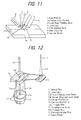
- a laser beam machining head which performs laser beam welding and arc welding simultaneously, has a configuration, for example, disclosed in Japanese Unexamined Patent Publication No. 1998-216972. As shown in FIG. 11, this laser beam machining head performs laser beam welding and arc welding by applying laser light 3 from a laser beam welding head 2 to a portion 1a, to be welded, of a base material 1, and simultaneously applying an arc discharge from an electrode 5 of a GMA welding head 4, while jetting a shielding gas at the portion 1a from a gas jet nozzle 6.
- this laser beam machining head is large in size as a whole, since the laser beam welding head 2 and the GMA welding head 4 are independent in the laser beam machining head.
- the laser beam machining head is not suitable, particularly, for three-dimensional machining by a robot.
- the inventors of the present invention proposed in Japanese Unexamined Patent Publication No. 1999-156573 a laser beam machining head capable of solving the above-described problems.
- this laser beam machining head as shown in FIG. 12, laser light 12 transmitted by an optical fiber 11 is reflected by a convex roof mirror 13 and a concave roof mirror 14, and divided thereby into two divisional beams, a first divisional laser beam 12a and a second divisional laser beam 12b, with a space portion 17 being formed therebetween.
- These divisional laser beams 12a and 12b are focused by a focusing lens array 15 onto a portion to be welded.
- the concave roof mirror 14 and the focusing lens array 15 are perforated, at the center thereof, with through-holes 14a and 15a, respectively.
- An electrode holding pipe 16 for holding an arc electrode such as a TIG electrode or a GMA electrode, is inserted through the through-holes 14a, 15a, whereby the arc electrode held by the electrode holding pipe 16 is located in the space portion 17 between the divisional laser beams 12a and 12b and rendered coaxial with these laser beams.
- the through-holes 14a and 15b are provided in the concave roof mirror 14 and the focusing lens array 15.
- the present invention has been accomplished to solve the above problems, and its object is to provide a coaxial laser beam machining head which is small in size, free from the risk of damaging optical instruments, and inexpensive, and a laser beam machining apparatus having this head.
- a laser beam machining head as a first aspect of the present invention for attaining the above object, comprises:
- the above laser beam machining head of the first aspect is very small in size, inexpensive, and free from the risk of damage to the optical instruments, in comparison with the conventional laser beam machining head.
- This laser beam machining head is so small in size that it can be easily mounted, for example, to a multi-axis NC robot.
- the tip machining portion of the machining means and the laser light are coaxial.
- the laser beam machining head can be easily positioned and moved to an arbitrary position by the multi-axis NC robot, and three-dimensional machining can be performed with ease.
- the tip machining portion of the machining means is a GMA electrode
- coaxial welding by this GMA electrode and the laser light makes welding at a very high speed possible.
- irradiation with laser light can stabilize an arc.
- welding of an SUS material or a high Cr material in a pure Ar gas atmosphere becomes possible, without the use of a special wire.
- a laser beam machining head as a second aspect of the invention is the laser beam machining head of the first aspect, wherein
- the rotation angle of the second reflecting mirror is set as desired to widen the spacing between the focused tip of the first divisional laser beam and the focused tip of the second divisional laser beam to a suitable degree, whereby a base material with a broad gap width can be welded.
- a laser beam machining head as a third aspect of the invention is the laser beam machining head of the first aspect, wherein
- the moving position of the first reflecting mirror is set as desired to decrease the proportion of the first divisional laser beam to a suitable degree and increase the proportion of the second divisional laser beam to a suitable degree
- the rotation angle of the second reflecting mirror is set as desired to widen the spacing between the focused tip of the first divisional laser beam and the focused tip of the second divisional laser beam to a suitable degree, whereby the second divisional laser beam is first applied to the base material with a deep weld penetration, and then the first divisional laser beam is applied to form an adequate bead. On this occasion, satisfactory welding without porosity (voids) can be performed.
- a laser beam machining head as a fourth aspect of the invention is the laser beam machining head of the first, second or third aspect, wherein
- the first divisional laser beam and the second divisional laser beam can be focused even by the focusing optical system of a smaller diameter, and the entire laser beam machining head can be made smaller in size.
- a laser beam machining head as a fifth aspect of the invention comprises:
- the laser beam machining head of the fifth aspect is very small in size, inexpensive, and free from the risk of damage to the optical instruments, in comparison with the conventional laser beam machining head.
- This laser beam machining head is so small in size that it can be easily mounted to a multi-axis NC robot.
- the tip machining portion of the machining means and the body of laser light are coaxial.
- the laser beam machining head can be easily positioned and moved to an arbitrary position by the multi-axis NC robot, and three-dimensional machining can be performed with ease.
- the tip machining portion of the machining means is a GMA electrode
- coaxial welding makes welding at a very high speed possible.
- welding of an SUS material or a high Cr material in a pure Ar gas atmosphere becomes possible.
- a laser beam machining head as a sixth aspect of the invention comprises:
- the laser beam machining head of the sixth aspect is very small in size, inexpensive, and free from the risk of damage to the optical instruments, in comparison with the conventional laser beam machining head.
- This laser beam machining head is so small in size that it can be easily mounted to a multi-axis NC robot.
- the tip machining portion of the machining means and the body of laser light are coaxial.
- the laser beam machining head can be easily positioned and moved to an arbitrary position by the multi-axis NC robot, and three-dimensional machining can be performed with ease.
- the tip machining portion of the machining means is a GMA electrode
- coaxial welding makes welding at a very high speed possible.
- welding of an SUS material or a high Cr material in a pure Ar gas atmosphere becomes possible.
- part of the laser light taken out of the body of the laser light by the first reflecting mirror is further reflected by the second reflecting mirror, and focused to the portion to be machined, together with the body of the laser light, by the focusing optical system.
- the energy of the laser light is not wasted, but can be effectively used, minimizing a loss of the laser light.
- a laser beam machining head as a seventh aspect of the invention is the laser beam machining head of the sixth aspect, wherein
- part of the laser light taken out of the body of the laser light is located just beside the body of the laser light.
- the diameter of the focusing optical system can be rendered smaller, and the entire laser beam machining head can be made smaller in size.
- a laser beam machining head as an eighth aspect of the invention is the laser beam machining head of the sixth or seventh aspect, wherein
- the body of the laser light and part of the laser light can be focused even by the focusing optical system of a smaller diameter, and the entire laser beam machining head can be made smaller in size.
- a laser beam machining head as a ninth aspect of the invention is the laser beam machining head of the first, second, third, fourth, fifth, sixth, seventh or eighth aspect, wherein
- the laser beam machining head of the ninth aspect is so small in size that it can be easily mounted to a multi-axis NC robot. Moreover, the laser beam machining head can be easily positioned and moved to an arbitrary position by the multi-axis NC robot. Furthermore, the laser beam machining head is inexpensive, and free from the risk of damaging the optical instruments.
- a laser beam machining head as a tenth aspect of the invention is the laser beam machining head of the first, second, third, fourth, fifth, sixth, seventh or eighth aspect, wherein
- the assist gas can be jetted at a very high speed, so that the cutting speed or the drilling speed increases markedly.
- a laser beam machining apparatus as an eleventh aspect of the invention comprises:
- the laser beam machining apparatus of the eleventh aspect is an inexpensive laser beam machining apparatus with excellent ability at machining, such as welding or cutting.
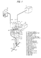
- FIG. 1 is a perspective view showing a system configuration of a laser beam machining apparatus according to Embodiment 1 of the present invention.
- FIG. 2A is a side view showing the configuration of an essential part of a laser beam machining head provided in the laser beam machining apparatus
- FIG. 2B is a sectional view taken on line E-E of FIG. 2A.
- FIGS. 3A to 3E are perspective views showing various machining means provided in the laser beam machining apparatus.
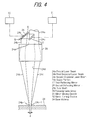
- FIG. 4 is an explanation drawing showing a state in which focused tips of laser beams formed by division in the laser beam machining head are spaced.
- FIG. 5 is an explanation drawing showing a state in which the division ratio for laser beams formed by division in the laser beam machining head is changed, and the focused tips of the laser beams are spaced.
- a laser beam machining apparatus As shown in FIG. 1, a laser beam machining apparatus according to the present Embodiment 1 is equipped with a YAG laser oscillator 21, an optical fiber 25 as laser beam transmission means, a laser beam machining head 22, and a multi-axis NC robot 23 as laser beam machining head moving means.
- Laser light 24 oscillated from the YAG laser oscillator 21 is transmitted to an input portion of the laser beam machining head 22 by the optical fiber 25.
- the laser beam machining head 22 is mounted to the multi-axis NC robot 23, and positioned and moved to an arbitrary position by the multi-axis NC robot 23.
- the laser beam machining head 22 has in an outer cylinder 30 a collimating lens array 26 as one collimating optical system, a first reflecting mirror 27, a second reflecting mirror 28, a focusing lens array 29 as one focusing optical system, and a GMA electrode (MIG electrode or the like) 33 as a tip machining portion of GMA welding means (MIG welding means or the like).
- a mirror turning device 32 comprising an electric motor or the like is provided as mirror turning means.
- a mirror moving device 31 comprising an electric motor or the like is provided as mirror moving means.
- the collimating lens array 26 is composed of a plurality of lenses arranged in series for making the laser light 24, which has been transmitted by the optical fiber 25, into a parallel beam.
- the first reflecting mirror 27 and the second reflecting mirror 28 are disposed below the collimating lens array 26 in the drawings, and the focusing lens array 29 is disposed below these reflecting mirrors 27 and 28 in the drawings.
- the first reflecting mirror 27 is a flat mirror, and is inserted into a laser beam 24a, which has been rendered parallel by the collimating lens array 26, in a direction perpendicular to the optical axis of the laser beam 24a as far as a central part of a cross sectional plane of the laser beam 24a, and a reflecting surface 27a of the first reflecting mirror 27 is inclined upward (toward the collimating lens array) and outward (leftward in the drawings).
- the first reflecting mirror 27 reflects part of the laser beam 24a (a left half thereof in the drawings) outward (leftward in the drawings) to divide the laser beam 24a into two halves, i.e., a first divisional laser beam 24b and a second divisional laser beam 24c.
- the second reflecting mirror 28 is a flat mirror similar to the first reflecting mirror 27.
- the second reflecting mirror 28 is disposed sideways of the first reflecting mirror 27, and has a reflecting surface 28a inclined downward (toward the focusing lens array) and toward the first reflecting mirror 27 (rightward in the drawings).
- the first divisional laser beam 24b reflected by the first reflecting mirror 27 is further reflected downward in the drawings parallel to the second divisional laser beam 24c to form a space portion (spacing) 24d between the first divisional laser beam 24b and the second divisional laser beam 24c.
- the focusing lens array 29 is composed of a plurality of lenses arranged in series, and focuses the first divisional laser beam 24b, which has been reflected by the first and second reflecting mirrors 27 and 28, and the second divisional laser beam 24c, which has been transmitted as such downwardly in the drawings without being reflected by the first reflecting mirror 27, onto a portion 34a, to be welded, of a base material 34.
- the first divisional laser beam 24b and the second divisional laser beam 24c are focused to one point. That is, the laser beam 24a is a parallel beam.
- the focusing lens array 29 is somewhat greater in diameter than the collimating lens array 26.
- the optical axis of the collimating lens array 26 and the optical axis of the focusing lens array 29 are displaced in a direction perpendicular to these optical axes, whereby the collimating lens array 26 is brought to one side (right side in the drawings) relative to the focusing lens array 29, and the first divisional laser beam 24b reflected by the first and second reflecting mirrors 27 and 28 is entered into the other side (left side in the drawings) of the focusing lens array 29.
- the second divisional laser beam 24c transmitted straightly from the collimating lens array 26 to the focusing lens array 29, and the first divisional laser beam 24b separated in a direction perpendicular to the optical axis with respect to the second divisional laser beam 24c (i.e., in a leftward direction in the drawings) are incident on the single focusing lens array 29. Since the single focusing lens array 29 focuses both of the divisional laser beams 24b and 24c, the entire laser beam machining head is very small in size.
- the diameter of the focusing lens array 29 is, for example, about 70 mm.
- the GMA electrode 33 is supported by the outer cylinder 30, and disposed in the space portion 24d between the first divisional laser beam 24b and the second divisional laser beam 24c coaxially with these laser beams.
- GMA welding means performs power supply and feeding of an inert gas from a GMA welding machine 36 to a GMA head 35 at the tip via a guide tube 38, and feeding of the GMA electrode (filler wire) 33 from a wire feeder 37, thereby carrying out GMA welding.
- a tip machining portion of any other machining means as shown in FIGS. 3A to 3E may be disposed in the space portion 24d between the first divisional laser beam 24b and the second divisional laser beam 24c.
- a TIG (tungsten) electrode 42 is held by a TIG head 41, and fed with an electric power and an inert gas from a TIG welding machine 43 via a guide tube 44 to perform TIG welding.
- the TIG electrode 42 is disposed in the space portion 24d between the first divisional laser beam 24b and the second divisional laser beam 24c coaxially with these laser beams. In this condition, laser beam welding and TIG welding are performed simultaneously.
- an assist gas fed from an assist gas feeder 62 via a guide tube 63 is jetted from an assist gas nozzle 61 located at the tip.
- the assist gas nozzle 61 is disposed in the space portion 24d between the first divisional laser beam 24b and the second divisional laser beam 24c coaxially with these laser beams.
- laser light is applied to a portion to be cut or drilled, with the assist gas being jetted at the portion to be cut or drilled, to perform laser beam cutting or drilling.
- the assist gas nozzle 61 is a nozzle of a shape having a channel once narrowed and then widened, as shown in FIG. 3D.
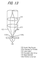
- Such a nozzle is generally known as a divergent nozzle in the field of gas cutting. So far, there has been a configuration, as shown in FIG. 13, in which an assist gas nozzle 103 is provided so as to surround the periphery of laser light 104 focused by a focusing lens array 105, and an assist gas is jetted from an opening tip portion 103a of the assist gas nozzle 103 toward a portion 106a, to be cut, of a base material 106. To increase the flow velocity of the assist gas, or to feed the assist gas efficiently to the portion 106a to be cut, it has been attempted to thin the opening tip portion 103a. However, there have been limits, because interference with laser light has to be avoided.
- the assist gas nozzle 61 when the assist gas nozzle 61 is disposed in the space portion 24d between the first divisional laser beam 24b and the second divisional laser beam 24c coaxially with these laser beams, as stated above, the assist gas nozzle 61 can be thinned to a desirable degree. Thus, the flow velocity of the assist gas can be increased, or the assist gas can be efficiently fed to the portion to be cut. Also, the assist gas can be brought to a desired pressure to increase the flow velocity and the flow rate.
- a divergent nozzle can be employed as the assist gas nozzle 61, so that the assist gas can be jetted at a very high speed, thereby increasing the cutting speed remarkably.
- a conventional coaxial assist gas nozzle as illustrated in FIG. 13 gave a cutting speed of about 0.05 m/min with the use of, for example, 8 kw laser light.
- the coaxial assist gas nozzle according to the present embodiment achieves a high cutting speed of 0.1 m/min with 4 kw laser light, for example.
- a powder of a metal (such as iron, stainless steel, or aluminum) fed from a powder feeder 72 via a guide tube 73 is ejected from a powder nozzle 71 located at the tip.
- the powder nozzle 71 is disposed in the space portion 24d between the first divisional laser beam 24b and the second divisional laser beam 24c coaxially with these laser beams.
- laser light is applied to the metal powder, with the metal powder being ejected from the powder nozzle 71, to form an arbitrary three-dimensional shape.
- the mirror turning device 32 rotates the second reflecting mirror 28 in a direction of an arrow A or the opposite direction of an arrow B about a center shaft 28b.
- the angle of reflection of the first divisional laser beam 24b by the second reflecting mirror 28 is changed to provide spacing d between a focused tip 24b-1 of the first divisional laser beam 24b and a focused tip 24c-1 of the second divisional laser beam 24c.
- This spacing d can be set, as desired, by adjusting the rotation angle of the second reflecting mirror 28.
- the mirror moving device 31 moves the first reflecting mirror 27 in a direction perpendicular to the optical axis of the laser beam 24a (i.e., in a direction of an arrow C or the opposite direction of an arrow D).
- the first reflecting mirror 27 is moved in the direction of the arrow C by the mirror moving device 31 as shown in FIG. 5
- the proportion of the first divisional laser beam 24b reflected by the first reflecting mirror 27 decreases, while the proportion of the second divisional laser beam 24c increases.
- This division ratio can be set, as desired, by adjusting the position to which the first reflecting mirror 27 is moved.
- the spacing d between the focused tip 24b-1 of the first divisional laser beam 24b and the focused tip 24c-1 of the second divisional laser beam 24c is enlarged.
- the movement of the first reflecting mirror 27 or the rotation of the second reflecting mirror 28 is not necessarily restricted to performance by the mirror moving device 31 or the mirror turning device 32, but may be performed manually.
- the laser beam machining head 22 is composed of the single collimating lens array 26 for making the laser light 24 into a parallel beam; the first reflecting mirror 27 for reflecting part of the laser beam 24a made parallel by the collimating lens array 26 to divide the laser beam 24a into the first divisional laser beam 24b and the second divisional laser beam 24c; the second reflecting mirror 28 for further reflecting the first divisional laser beam 24b reflected by the first reflecting mirror 27 to provide the space portion 24d between the first divisional laser beam 24b and the second divisional laser beam 24c; the single focusing lens array 29 for focusing the first divisional laser beam 24b and the second divisional laser beam 24c onto the portion 34a to be cut; and the GMA electrode 33 disposed in the space portion 24d between the first divisional laser beam 24b and the second divisional laser beam 24c coaxially with the laser beams.
- the laser beam machining head 22 obtains the following actions and effects:
- the arc can be stabilized by application of the laser beams 24b, 24c as stated earlier.
- welding of an SUS material or a high Cr material can be performed in a pure Ar gas atmosphere without the use of a special wire.
- the same actions and effects as described above can be obtained. Since the laser beam machining head 22 is very compact, its mounting on the multi-axis NC robot 23 is easy, and the laser beam machining head 22 can be easily positioned and moved to an arbitrary position by the multi-axis NC robot 23. Also, the laser beam machining head 22 is inexpensive, is free from the risk of damaging optical instruments, makes high speed welding possible, and permits welding in a pure Ar gas atmosphere.
- the laser beam machining head 22 is very compact, its mounting on the multi-axis NC robot 23 is easy, and the laser beam machining head 22 can be easily positioned and moved to an arbitrary position by the multi-axis NC robot 23. Also, the laser beam machining head 22 is inexpensive, and is free from the risk of damaging optical instruments.
- the assist gas nozzle 61 When the assist gas nozzle 61 is disposed coaxially in the laser beam machining head 22, the following actions and effects can be obtained: Since the laser beam machining head 22 is very compact, its mounting on the multi-axis NC robot 23 is easy, and the laser beam machining head 22 can be easily positioned and moved to an arbitrary position by the multi-axis NC robot 23. Also, the laser beam machining head 22 is inexpensive, and is free from the risk of damaging optical instruments. Moreover, the assist gas nozzle 61 can be thinned to a desirable degree to increase the flow velocity of the assist gas or feed the assist gas efficiently to the portion to be cut or drilled. Furthermore, the assist gas can be brought to a desired pressure to increase the flow velocity and the flow rate. Besides, a divergent nozzle can be employed as the assist gas nozzle 61, so that the assist gas can be jetted at a very high speed, thereby increasing the cutting speed or drilling speed remarkably.
- the laser beam machining head 22 is very compact, its mounting on the multi-axis NC robot 23 is easy, and the laser beam machining head 22 can be easily positioned and moved to an arbitrary position by the multi-axis NC robot 23. Also, the laser beam machining head 22 is inexpensive, and is free from the risk of damaging optical instruments.
- the spacing between the first divisional laser beam 24b and the second divisional laser beam 24c may be rendered adjustable by making the second reflecting mirror 28 rotatable by means of the mirror turning device 32 or by a manual operation.
- the rotation angle of the second reflecting mirror 28 is set appropriately to enlarge the spacing d between the focused tip 24b-1 of the first divisional laser beam 24b and the focused tip 24c-1 of the second divisional laser beam 24c appropriately, as shown in FIG. 4.
- the base material 34 with a large gap width e.g., a gap width of 1 mm
- the division ratio between the first divisional laser beam 24b and the second divisional laser beam 24c may be rendered adjustable by making the first reflecting mirror 27 movable by means of the mirror moving device 31 or by a manual operation
- the spacing between the first, divisional laser beam 24b and the second divisional laser beam 24c may be rendered adjustable by making the second reflecting mirror 28 rotatable by means of the mirror turning device 32 or by a manual operation. In this case, as shown in FIG.
- the moving position of the first reflecting mirror 27 is appropriately set to decrease the proportion of the first divisional laser beam 24b appropriately and increase the proportion of the second divisional laser beam 24c appropriately, and the rotation angle of the second reflecting mirror 28 is appropriately set to enlarge the spacing d between the focused tip 24b-1 of the first divisional laser beam 24b and the focused tip 24c-1 of the second divisional laser beam 24c appropriately.
- the second divisional laser beam 24c is first applied to the base material 34 as indicated by an arrow F to achieve deep weld penetration, and then the first divisional laser beam 24b is applied, whereby a high quality bead can be formed. At this time, satisfactory welding free from porosity (voids) can be performed.
- porosity tends to occur in the portion to be welded.
- porosity which has been once enclosed during application of the second divisional laser beam 24c, is broken open by irradiation with the first divisional laser beam 24b, whereby the porosity can be eliminated.
- the coaxial laser beam machining head 22 is configured such that the optical axis of the collimating lens array 26 and the optical axis of the focusing lens array 29 are displaced in a direction perpendicular to the optical axes, whereby the collimating lens array 26 is moved over toward one side relative to the focusing lens array 29 so that the first divisional laser beam 24b reflected by the first and second reflecting mirrors 27 and 28 is entered into the other side of the focusing lens array 29.
- the first divisional laser beam 24b and the second divisional laser beam 24c can be focused even by the focusing lens array 29 of a smaller diameter, and the entire laser beam machining head can be made smaller in size.
- the laser beam machining apparatus provided with the above-described laser beam machining head 22 is an inexpensive laser beam machining apparatus with excellent machining ability for welding and cutting.
- FIG. 6 is a perspective view showing a system configuration of a laser beam machining apparatus according to Embodiment 2 of the present invention.
- FIGS. 7A and 7B are side views showing the configuration of an essential part of a laser beam machining head provided in the laser beam machining apparatus, FIG. 7A being a view as viewed in a direction of an arrow G in FIG. 9A, and FIG. 7B being a view as viewed in a direction of an arrow H in FIG. 9A.
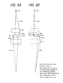
- FIGS. 8A and 8B are side views showing only part of laser light reflected by reflecting mirrors, FIG. 8A being a view corresponding to FIG. 7A, and FIG. 8B being a view corresponding to FIG. 7B.
- FIG. 8A being a view corresponding to FIG. 7A
- FIG. 8B being a view corresponding to FIG. 7B.
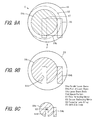
- FIGS. 10A to 10D are explanation drawings showing other arrangement examples of reflecting mirrors, in which FIG. 10A is a side view, FIG. 10B is a view as viewed from a direction of L in FIG. 10A, FIG. 10C is a sectional view taken on line M-M of FIG. 10A, and FIG. 10D is a sectional view taken on line N-N of FIG. 10A.
- the laser beam machining apparatus has a YAG laser oscillator 81, an optical fiber 85 as laser light transmission means, a laser beam machining head 82, and a multi-axis NC robot 83 as laser beam machining head moving means.
- Laser light 84 oscillated from the YAG laser oscillator 81 is transmitted to an input portion of the laser beam machining head 82 by the optical fiber 85.
- the laser beam machining head 82 is mounted on the multi-axis NC robot 83, and positioned and moved to an arbitrary position by the multi-axis NC robot 83.
- the laser beam machining head 82 has in an outer cylinder 90 a collimating lens array 86 as one collimating optical system, a first reflecting mirror 87, a second reflecting mirror 88, a focusing lens array 89 as one focusing optical system, and a GMA electrode (MIG electrode or the like) 33 as a tip machining portion of GMA welding means (MIG welding means or the like).
- a collimating lens array 86 as one collimating optical system
- a first reflecting mirror 87, a second reflecting mirror 88, a focusing lens array 89 as one focusing optical system
- GMA electrode MIG electrode or the like
- the collimating lens array 86 is composed of a plurality of lenses arranged in series for making laser light 84, which has been transmitted by the optical fiber 85, into a parallel beam.
- the first reflecting mirror 87 and the second reflecting mirror 88 are disposed below the collimating lens array 86 in the drawings, and the focusing lens array 89 is disposed below these reflecting mirrors 87 and 88 in the drawings.
- the first reflecting mirror 87 is a slender, rectangular, flat mirror having a predetermined width (a width which enables a space portion of a desired width to be formed in a body of the laser light).
- the first reflecting mirror 87 is inserted into a laser beam 84a, which has been rendered parallel by the collimating lens array 86, horizontally along a diametrical direction of a cross sectional plane of the laser beam 84a (in a direction perpendicular to the optical axis of the laser beam 84a) as far as a central part of the cross sectional plane (see FIGS.
- a reflecting surface 87a of the first reflecting mirror 87 is inclined upward (toward the collimating lens array) and in a direction perpendicular to the direction of insertion of the first reflecting mirror 87 (see FIGS. 7B and 8B; inclined rightward in the drawings in the illustrated embodiment).
- the first reflecting mirror 87 reflects part 84b of the laser beam 84a to withdraw it out of a laser beam body 84c.
- a slender space portion 84d is formed in the laser beam body 84c (FIGS. 7B and 8B).
- the second reflecting mirror 88 is a slender, flat mirror similar to the first reflecting mirror 87.
- the second reflecting mirror 88 is disposed outside the laser beam body 84c, and has a reflecting surface 88a inclined downward (toward the focusing lens array) and toward the first reflecting mirror 87.
- the part 84b of the laser light reflected by the first reflecting mirror 87 is reflected so as to be parallel to the laser beam body 84c and to be contiguous to or close to the outer peripheral surface of the laser beam body 84c (see FIGS. 7B and 9B).
- the part 84b of the laser light is in contact with the outer peripheral surface of the laser beam body 84c, thereby making the diameter of the focusing lens array 89 as small as possible.
- the arrangement of the first and second reflecting mirrors 87 and 88 is not restricted to the above-mentioned arrangement, but may be as shown in FIG. 10A to 10D.
- the first reflecting mirror 87 is inserted into the laser beam 84a along the diametrical direction of the cross sectional plane of the laser beam 84a and obliquely with respect to the optical axis of the laser beam 84a (obliquely toward the focusing lens array) (see FIG. 10A), with the reflecting surface 87a being directed upward (toward the collimating lens array), and is inclined in a direction perpendicular to the direction of insertion of the first reflecting mirror 87 (see FIG. 10B).
- the first reflecting mirror 87 reflects part 84b of the laser light outwardly of the laser beam body 84c and obliquely (see FIG. 10C).
- the second reflecting mirror 88 is disposed outside the laser beam body 84c, is oblique relative to the optical axis of the laser beam 84a like the first reflecting mirror 87, and is inclined toward the first reflecting mirror 87 (see FIG. 10B), with its reflecting surface 88a being directed downward (toward the focusing lens array).
- the part 84b of the laser light reflected by the first reflecting mirror 87 is reflected so as to be parallel to the laser beam body 84c and to be contiguous to or close to the outer peripheral surface of the laser beam body 84c (see FIG. 10B).
- the part 84b of the laser light is positioned directly beside the laser beam body 84c, as shown in FIG. 10D.
- the diameter of the focusing lens array 89 can be made smaller than when the part 84b of the laser light is located at a position displaced from the position just beside the laser beam body 84c, as shown in FIG. 9B.
- the focusing lens array 89 is composed of a plurality of lenses arranged in series, and focuses the laser beam body 84c, in which the space portion 84d has been formed by the first reflecting mirror 87, and the part 84b of the laser light, which has been reflected by the first and second reflecting mirrors 87 and 88, onto a portion 94a, to be welded, of a base material 94.
- the laser beam body 84c and the part 84b of the laser light are focused to one point. That is, the laser beam 84a is a parallel beam.
- the focusing lens array 89 is somewhat greater in diameter than the collimating lens array 86.
- the optical axis of the collimating lens array 86 and the optical axis of the focusing lens array 89 are displaced in a direction perpendicular to these optical axes, whereby the collimating lens array 86 is brought to one side (left side in FIG.
- the laser beam body 84c transmitted straightly from the collimating lens array 86 to the focusing lens array 89, and the part 84b of the laser light withdrawn outside of the laser beam body 84c are incident on the single focusing lens array 89. Since the single focusing lens array 89 focuses both of the laser beam body 84c and the part 84b of the laser light, the entire laser beam machining head is very small in size.
- the diameter of the focusing lens array 89 is, for example, about 70 mm.
- the GMA electrode 93 is supported by the outer cylinder 90 and disposed in the space portion 84d of the laser beam body 84c coaxially with the laser beam body.
- GMA/YAG coaxial welding is possible.
- an electric power and an inert gas are fed from a GMA welding machine 96 to a GMA head 95 at the tip via a guide tube 98, and a GMA electrode (filler wire) 93 is fed from a wire feeder 97, whereby GMA welding is performed.
- the tip machining portion of any other machining means as shown in FIGS. 3A to 3E may be disposed in the space portion 84d of the laser beam body 84c coaxially with the laser beam body 84c, as in the aforementioned Embodiment 1, although concrete explanations for these alternatives are omitted.
- the laser beam machining head 82 is composed of the single collimating lens array 86 for making the laser light 84 into a parallel beam; the first reflecting mirror 87 for reflecting part 84b of the laser beam 84a made parallel by the collimating lens array 86 to withdraw the part 84b of the laser beam 84a outside of the laser beam body 84c, thereby forming the space portion 84d in the laser beam body 84c; the second reflecting mirror 88 disposed outside the laser beam body 84c and adapted to reflect the part 84b of the laser light reflected by the first reflecting mirror 87 so as to be parallel to the laser beam body 84c and contact or approach the outer peripheral surface of the laser beam body 84c; the single focusing lens array 89 for focusing the laser beam body 84c, in which the space portion 84d has been formed by the first reflecting mirror 87, and the part 84b of the laser
- the laser beam machining head 22 is very small in size and inexpensive, and is free from the risk of damaging optical instruments, in comparison with conventional laser beam machining heads. Since the laser beam machining head 82 is very compact, moreover, it can be easily mounted on the multi-axis NC robot 83. Since the GMA electrode 83 and the YAG laser light 84 (laser beam body 84c) are coaxial, furthermore, the laser beam machining head 82 can be easily positioned and moved to an arbitrary position by the multi-axis NC robot 83, and can perform three-dimensional machining easily.
- welding can be performed at a very high speed by coaxial welding using the GMA electrode 83 and the YAG laser light 84 (the laser beam body 84c and part 84b of the laser light).
- welding of an SUS material or a high Cr material in a pure Ar gas atmosphere also becomes possible.
- the part 84b of the laser beam taken out of the laser beam body 84c by the first reflecting mirror 87 is further reflected by the second reflecting mirror 88, and focused, along with the laser beam body 84c, onto the portion 94a, to be welded, by the focusing lens array 89.
- the energy of the laser light 84 can be effectively used without waste to minimize the loss of the laser light 84.
- the first reflecting mirror 87 is inserted into the laser beam 84a, which has been rendered parallel by the collimating lens array 86, along a diametrical direction of the cross sectional plane of the laser beam 84a and obliquely relative to the optical axis of the laser beam 84a, and is inclined in a direction perpendicular to the direction of insertion of the first reflecting mirror 87.
- part 84b of the laser beam is reflected obliquely to the outside of the laser beam body 84c.
- part 84b of the laser light is positioned just beside the laser beam body 84c.
- the diameter of the focusing lens array 89 can be rendered smaller, and the entire laser beam machining head can be made smaller in size.
- the laser beam machining head 82 is configured such that the optical axis of the collimating lens array 86 and the optical axis of the focusing lens array 89 are displaced in a direction perpendicular to the optical axes, whereby the collimating lens array 86 is moved over toward one side relative to the focusing lens array 89 so that part 84b of the laser light reflected by the first and second reflecting mirrors 87 and 88 is entered into the other side of the focusing lens array 89.
- the laser beam body 84c and part 84b of the laser beam can be focused even by the focusing lens array 89 of a smaller diameter, and the entire laser beam machining head can be made smaller in size.
- the laser beam machining apparatus provided with the above-described laser beam machining head 82 is an inexpensive laser beam machining apparatus with excellent machining ability for welding and cutting.
Landscapes
- Physics & Mathematics (AREA)
- Optics & Photonics (AREA)
- Engineering & Computer Science (AREA)
- Plasma & Fusion (AREA)
- Mechanical Engineering (AREA)
- Robotics (AREA)
- Laser Beam Processing (AREA)
- Arc Welding In General (AREA)
Abstract
Description
Claims (11)
- A laser beam machining head comprising:one collimating optical system for making laser light into a parallel beam;a first reflecting mirror for reflecting part of the laser light made into the parallel beam by the collimating optical system to divide the laser light into two beams, a first divisional laser beam and a second divisional laser beam;a second reflecting mirror for further reflecting the first divisional laser beam reflected by the first reflecting mirror to form a space portion between the first divisional laser beam and the second divisional laser beam;one focusing optical system for focusing the first divisional laser beam and the second divisional laser beam onto a portion to be machined; anda tip machining portion of machining means disposed in the space portion between the first divisional laser beam and the second divisional laser beam coaxially with the laser beams.
- The laser beam machining head of claim 1, whereinthe second reflecting mirror is rendered normally and reversely rotatable, whereby spacing between a focused tip of the first divisional laser beam and a focused tip of the second divisional laser beam is adjustable.
- The laser beam machining head of claim 1, whereinthe first reflecting mirror is rendered movable, whereby a division ratio for the first divisional laser beam and the second divisional laser beam can be adjusted, and the second reflecting mirror is rendered normally and reversely rotatable, whereby spacing between a focused tip of the first divisional laser beam and a focused tip of the second divisional laser beam can be adjusted.
- The laser beam machining head of claim 1, 2 or 3, whereinan optical axis of the collimating optical system and an optical axis of the focusing optical system are displaced in a direction perpendicular to the optical axes, whereby the collimating optical system is moved over toward one side relative to the focusing optical system so that the first divisional laser beam reflected by the first and second reflecting mirrors is entered into other side of the focusing optical system.
- A laser beam machining head comprising:one collimating optical system for making laser light into a parallel beam;a reflecting mirror for reflecting part of the laser light made into the parallel beam by the collimating optical system to withdraw the part of the laser light out of a body of the laser light, thereby forming a space portion in the body of the laser light;one focusing optical system for focusing the body of the laser light, where the space portion has been formed, onto a portion to be machined; anda tip machining portion of machining means disposed in the space portion of the body of the laser light coaxially with the body of the laser light.
- A laser beam machining head comprising:one collimating optical system for making laser light into a parallel beam;a first reflecting mirror for reflecting part of the laser light made into the parallel beam by the collimating optical system to withdraw the part of the laser light out of a body of the laser light, thereby forming a space portion in the body of the laser light;a second reflecting mirror located outside the body of the laser light and adapted to reflect the part of the laser light reflected by the first reflecting mirror so as to be parallel to the body of the laser light and be in contact with or in proximity to an outer peripheral surface of the body of the laser light;one focusing optical system for focusing the body of the laser light, where the space portion has been formed by the first reflecting mirror, and the part of the laser light reflected by the first and second reflecting mirrors, onto a portion to be machined; anda tip machining portion of machining means disposed in the space portion of the body of the laser light coaxially with the body of the laser light.
- The laser beam machining head of claim 6, whereinthe first reflecting mirror is inserted into the laser light, which has been made into the parallel beam by the collimating optical system, along a diametrical direction of a cross sectional plane of the laser light and obliquely relative to an optical axis of the laser light, and is also inclined in a direction perpendicular to a direction of insertion of the first reflecting mirror, whereby the part of the laser light is reflected obliquely to an outside of the body of the laser light.
- The laser beam machining head of claim 6 or 7, whereinan optical axis of the collimating optical system and an optical axis of the focusing optical system are displaced in a direction perpendicular to the optical axes, whereby the collimating optical system is moved over toward one side relative to the focusing optical system so that the part of the laser light reflected by the first and second reflecting mirrors is entered into other side of the focusing optical system.
- The laser beam machining head of claim 1, 2, 3, 4, 5, 6, 7 or 8, whereinthe tip machining portion of the machining means is a GMA electrode, a TIG electrode, a filler wire, an assist gas nozzle, or a powder nozzle.
- The laser beam machining head of claim 1, 2, 3, 4, 5, 6, 7 or 8, whereinthe tip machining portion of the machining means is the assist gas nozzle, and the assist gas nozzle is a divergent nozzle.
- A laser beam machining apparatus comprising:the laser beam machining head of claim 1, 2, 3, 4, 5, 6, 7, 8, 9 or 10;a laser oscillator for oscillating laser light;laser light transmission means for transmitting the laser light oscillated by the laser oscillator to the laser beam machining head; andlaser beam machining head moving means for positioning and moving the laser beam machining head to an arbitrary position.
Applications Claiming Priority (2)
| Application Number | Priority Date | Filing Date | Title |
|---|---|---|---|
| JP2000242367 | 2000-08-10 | ||
| JP2000242367A JP3686317B2 (en) | 2000-08-10 | 2000-08-10 | Laser processing head and laser processing apparatus provided with the same |
Publications (3)
| Publication Number | Publication Date |
|---|---|
| EP1179382A2 true EP1179382A2 (en) | 2002-02-13 |
| EP1179382A3 EP1179382A3 (en) | 2004-08-18 |
| EP1179382B1 EP1179382B1 (en) | 2007-12-19 |
Family
ID=18733398
Family Applications (1)
| Application Number | Title | Priority Date | Filing Date |
|---|---|---|---|
| EP01118789A Expired - Lifetime EP1179382B1 (en) | 2000-08-10 | 2001-08-09 | Laser beam machining head and laser beam machining apparatus having same |
Country Status (4)
| Country | Link |
|---|---|
| US (1) | US6608281B2 (en) |
| EP (1) | EP1179382B1 (en) |
| JP (1) | JP3686317B2 (en) |
| DE (1) | DE60131935T2 (en) |
Cited By (14)
| Publication number | Priority date | Publication date | Assignee | Title |
|---|---|---|---|---|
| WO2003082511A1 (en) * | 2002-04-01 | 2003-10-09 | Honda Giken Kogyo Kabushiki Kaisha | Yag laser induced arc filler wire composite welding method and welding equipment |
| WO2005118209A1 (en) * | 2004-05-27 | 2005-12-15 | Hentze-Lissotschenko Patentverwaltungs Gmbh & Co. Kg | Device for welding or soldering by means of laser radiation |
| CN100387380C (en) * | 2006-03-01 | 2008-05-14 | 苏州大学 | A laser spot-variable cladding molding process and a coaxial nozzle used in the process |
| EP1935552A2 (en) | 2006-12-20 | 2008-06-25 | Erlas Erlanger Lasertechnik GmbH | Multi-beam laser processing head |
| US7974735B2 (en) * | 2004-12-10 | 2011-07-05 | Kabushiki Kaisha Yaskawa Denki | Laser tool robot system with coordinated drive shaft control |
| WO2012052525A1 (en) * | 2010-10-23 | 2012-04-26 | Trumpf Werkzeugmaschinen Gmbh + Co. Kg | Device for the highly dynamic movement of the working point of a beam |
| DE102012207201B3 (en) * | 2012-04-30 | 2013-04-11 | Trumpf Werkzeugmaschinen Gmbh + Co. Kg | Method for laser-assisted plasma cutting or plasma welding and apparatus therefor |
| US20130309000A1 (en) * | 2012-05-21 | 2013-11-21 | General Electric Comapny | Hybrid laser arc welding process and apparatus |
| WO2015086781A1 (en) * | 2013-12-12 | 2015-06-18 | Autotech Engineering A.I.E. | Methods for joining two blanks and blanks and products obtained |
| CN105499793A (en) * | 2016-01-26 | 2016-04-20 | 华中科技大学 | Light path beam-splitting unit of coaxial wire-feeding and depositing laser head |
| CN106944756A (en) * | 2017-03-05 | 2017-07-14 | 北京工业大学 | The double light beam laser TIG composite welding process that a kind of thin plate butt welding shapes only |
| CN107520444A (en) * | 2016-06-20 | 2017-12-29 | 黄吉川 | Deposition apparatus and deposition method |
| US10471544B2 (en) | 2014-05-09 | 2019-11-12 | Autotech Engineering A.I.E. | Methods for joining two blanks |
| CN112548322A (en) * | 2020-11-23 | 2021-03-26 | 上海嘉强自动化技术有限公司 | Double-beam laser welding equipment |
Families Citing this family (74)
| Publication number | Priority date | Publication date | Assignee | Title |
|---|---|---|---|---|
| US7045015B2 (en) | 1998-09-30 | 2006-05-16 | Optomec Design Company | Apparatuses and method for maskless mesoscale material deposition |
| JP3686317B2 (en) | 2000-08-10 | 2005-08-24 | 三菱重工業株式会社 | Laser processing head and laser processing apparatus provided with the same |
| US7286223B2 (en) | 2003-03-18 | 2007-10-23 | Loma Linda University Medical Center | Method and apparatus for detecting embedded rebar within an interaction region of a structure irradiated with laser light |
| US7880116B2 (en) * | 2003-03-18 | 2011-02-01 | Loma Linda University Medical Center | Laser head for irradiation and removal of material from a surface of a structure |
| US7057134B2 (en) | 2003-03-18 | 2006-06-06 | Loma Linda University Medical Center | Laser manipulation system for controllably moving a laser head for irradiation and removal of material from a surface of a structure |
| US6947454B2 (en) * | 2003-06-30 | 2005-09-20 | Electro Scientific Industries, Inc. | Laser pulse picking employing controlled AOM loading |
| CA2489941C (en) * | 2003-12-18 | 2012-08-14 | Comau S.P.A. | A method and device for laser welding |
| ITTO20040361A1 (en) * | 2004-05-28 | 2004-08-28 | Comau Spa | METHOD AND DEVICE FOR REMOTE LASER WELDING USING A ROBOT, WITH SIMPLIFIED CONTROL OF THE FOCUSING DIRECTION OF THE LASER BEAM. |
| US7938341B2 (en) | 2004-12-13 | 2011-05-10 | Optomec Design Company | Miniature aerosol jet and aerosol jet array |
| US7674671B2 (en) | 2004-12-13 | 2010-03-09 | Optomec Design Company | Aerodynamic jetting of aerosolized fluids for fabrication of passive structures |
| US7253377B2 (en) * | 2005-02-08 | 2007-08-07 | General Motors Corporation | System and method of joining overlapping workpieces |
| US20060261045A1 (en) * | 2005-05-18 | 2006-11-23 | Pei-Chung Wang | Multi-heat source laser brazing system and method |
| US7879394B1 (en) * | 2006-06-02 | 2011-02-01 | Optomec, Inc. | Deep deposition head |
| JP2008296266A (en) * | 2007-06-01 | 2008-12-11 | Nippon Sharyo Seizo Kaisha Ltd | Laser cutting apparatus |
| TWI482662B (en) | 2007-08-30 | 2015-05-01 | 阿普托麥克股份有限公司 | Mechanically integrated and tightly coupled print heads and spray sources |
| CN101386111A (en) * | 2007-09-14 | 2009-03-18 | 苏州大学 | Laser optical inner wire feeding cladding method and optical inner wire feeding device |
| JP2009195964A (en) * | 2008-02-25 | 2009-09-03 | Mitsubishi Heavy Ind Ltd | Laser arc composite welding head |
| JP5398165B2 (en) * | 2008-04-24 | 2014-01-29 | 三菱重工業株式会社 | Laser / arc combined welding head and method thereof |
| DE102009020146B3 (en) * | 2009-04-08 | 2010-06-10 | V & M Deutschland Gmbh | Connecting ends of steel tubes by orbital welding in laser-light-arc hybrid technology, comprises connecting tube ends with welding positions, and guiding laser- and light arc welding head as tool over guiding ring during welding process |
| US20100288738A1 (en) * | 2009-05-15 | 2010-11-18 | General Electric Company | Welding apparatus and method |
| WO2011055373A1 (en) * | 2009-11-03 | 2011-05-12 | The Secretary, Department Of Atomic Energy,Govt.Of India. | Niobium based superconducting radio frequency (scrf) cavities comprising niobium components joined by laser welding; method and apparatus for manufacturing such cavities |
| JP5646646B2 (en) * | 2009-12-16 | 2014-12-24 | イーエスエービー・エービー | Welding method and welding apparatus |
| WO2011127601A1 (en) * | 2010-04-13 | 2011-10-20 | National Research Council Of Canada | Laser processing control method |
| US8378248B2 (en) | 2010-05-21 | 2013-02-19 | General Electric Company | System and method for heat treating a weld joint |
| CN102248303A (en) * | 2011-01-13 | 2011-11-23 | 苏州德龙激光有限公司 | Picosecond laser device for processing blood vessel stent |
| US12397363B2 (en) | 2011-03-31 | 2025-08-26 | Norsk Titanium As | Method and arrangement for building metallic objects by solid freeform fabrication |
| GB2489493B (en) | 2011-03-31 | 2013-03-13 | Norsk Titanium Components As | Method and arrangement for building metallic objects by solid freeform fabrication |
| JP2012210659A (en) * | 2012-07-23 | 2012-11-01 | Sumitomo Metal Ind Ltd | Laser welding method and laser welding device |
| JP2012210660A (en) * | 2012-07-23 | 2012-11-01 | Sumitomo Metal Ind Ltd | Laser welding method and laser welding device |
| JP2012236228A (en) * | 2012-07-23 | 2012-12-06 | Nippon Steel & Sumitomo Metal Corp | Laser welding method and laser welding device |
| US10328513B2 (en) * | 2013-05-31 | 2019-06-25 | General Electric Company | Welding process, welding system, and welded article |
| CN104289811A (en) * | 2013-07-18 | 2015-01-21 | 沈阳新松机器人自动化股份有限公司 | Multi-beam center wire feeding laser processing head and processing method thereof |
| US11141815B2 (en) * | 2013-09-24 | 2021-10-12 | Ipg Photonics Corporation | Laser processing systems capable of dithering |
| GB2546016B (en) | 2014-06-20 | 2018-11-28 | Velo3D Inc | Apparatuses, systems and methods for three-dimensional printing |
| DE102015101263B4 (en) * | 2015-01-28 | 2016-12-15 | Precitec Gmbh & Co. Kg | Device for processing materials by means of laser radiation |
| CN104668562B (en) * | 2015-01-30 | 2017-02-22 | 湖南大学 | Shielding-free laser-path-coaxial powder conveying method and shielding-free laser-path-coaxial powder conveying device |
| WO2016130709A1 (en) | 2015-02-10 | 2016-08-18 | Optomec, Inc. | Fabrication of three-dimensional structures by in-flight curing of aerosols |
| JP2018535121A (en) | 2015-11-06 | 2018-11-29 | ヴェロ・スリー・ディー・インコーポレイテッド | Proficient 3D printing |
| US10207454B2 (en) | 2015-12-10 | 2019-02-19 | Velo3D, Inc. | Systems for three-dimensional printing |
| KR101728504B1 (en) * | 2015-12-18 | 2017-04-19 | (주)엔에스 | Laser cutting device |
| EP3265263B1 (en) * | 2016-02-23 | 2018-12-12 | Fronius International GmbH | Welding device with a laser preheating device for filler wire |
| US11691343B2 (en) | 2016-06-29 | 2023-07-04 | Velo3D, Inc. | Three-dimensional printing and three-dimensional printers |
| WO2018005439A1 (en) | 2016-06-29 | 2018-01-04 | Velo3D, Inc. | Three-dimensional printing and three-dimensional printers |
| EP3481579A1 (en) | 2016-07-08 | 2019-05-15 | Norsk Titanium AS | Method and arrangement for building metallic objects by solid freeform fabrication with two welding guns |
| US20180095450A1 (en) | 2016-09-30 | 2018-04-05 | Velo3D, Inc. | Three-dimensional objects and their formation |
| CN106392314B (en) * | 2016-11-01 | 2018-05-22 | 苏州大学 | Laser melting coating feed device |
| CN106312304B (en) * | 2016-11-01 | 2018-09-04 | 苏州大学 | Laser melting coating feed device |
| US10661341B2 (en) | 2016-11-07 | 2020-05-26 | Velo3D, Inc. | Gas flow in three-dimensional printing |
| KR102520120B1 (en) | 2017-01-05 | 2023-04-07 | 아이피지 포토닉스 코포레이션 | Additional laser machining systems and methods |
| WO2018160807A1 (en) * | 2017-03-02 | 2018-09-07 | Velo3D, Inc. | Three-dimensional printing of three dimensional objects |
| US10449696B2 (en) | 2017-03-28 | 2019-10-22 | Velo3D, Inc. | Material manipulation in three-dimensional printing |
| JP7014226B2 (en) | 2017-05-01 | 2022-02-01 | 株式会社ニコン | Processing equipment |
| JP6972670B2 (en) * | 2017-06-02 | 2021-11-24 | 株式会社豊田中央研究所 | Laser processing equipment |
| US11383316B2 (en) | 2017-10-16 | 2022-07-12 | Karl F. HRANKA | Wire arc hybrid manufacturing |
| EP3723909B1 (en) | 2017-11-13 | 2023-10-25 | Optomec, Inc. | Shuttering of aerosol streams |
| US10272525B1 (en) | 2017-12-27 | 2019-04-30 | Velo3D, Inc. | Three-dimensional printing systems and methods of their use |
| WO2020090074A1 (en) | 2018-10-31 | 2020-05-07 | 株式会社ニコン | Processing system and processing method |
| WO2020090075A1 (en) | 2018-10-31 | 2020-05-07 | 株式会社ニコン | Processing system and processing method |
| JP7098053B2 (en) | 2019-03-29 | 2022-07-08 | Dmg森精機株式会社 | Processing machine |
| CA3148849A1 (en) | 2019-07-26 | 2021-02-04 | Velo3D, Inc. | Quality assurance in formation of three-dimensional objects |
| US20210031297A1 (en) * | 2019-08-01 | 2021-02-04 | GM Global Technology Operations LLC | System and method for multi-task laser welding |
| IL290911B2 (en) * | 2019-08-27 | 2026-01-01 | Edison Welding Inst Inc | Coaxial laser-wire optical system for use in additive manufacturing |
| EP3892414A1 (en) * | 2020-04-06 | 2021-10-13 | Bystronic Laser AG | Laser processing machine |
| JP7485014B2 (en) | 2020-04-15 | 2024-05-16 | 株式会社ニコン | Processing systems and measuring components |
| FR3118598B1 (en) * | 2021-01-04 | 2023-06-23 | Sotimeco | LASER 3D PRINTING HEAD |
| TW202247905A (en) | 2021-04-29 | 2022-12-16 | 美商阿普托麥克股份有限公司 | High reliability sheathed transport path for aerosol jet devices |
| JPWO2023073833A1 (en) | 2021-10-27 | 2023-05-04 | ||
| EP4527541A4 (en) | 2022-05-19 | 2026-04-29 | Nikon Corp | PROCESSING METHOD AND PROCESSING EQUIPMENT |
| US20250319544A1 (en) | 2022-05-27 | 2025-10-16 | Nikon Corporation | Processing system |
| US12589447B2 (en) | 2022-05-30 | 2026-03-31 | Ii-Vi Delaware, Inc. | Laser beam brilliance enhancing beam splitting for laser welding/brazing |
| CN115007851B (en) * | 2022-06-20 | 2024-02-06 | 华材(山东)新材料有限公司 | Device and method for producing superfine spherical ruthenium powder for 3D printing by one-step method |
| WO2024105851A1 (en) | 2022-11-17 | 2024-05-23 | 株式会社ニコン | Processing system |
| CN117564454B (en) * | 2023-12-29 | 2026-04-21 | 无锡锐科光纤激光技术有限责任公司 | Laser coaxial hot filament device and method |
| GB2641393A (en) * | 2024-05-30 | 2025-12-03 | Gkn Aerospace Services Ltd | System and method for laser deposition |
Family Cites Families (14)
| Publication number | Priority date | Publication date | Assignee | Title |
|---|---|---|---|---|
| US4167662A (en) * | 1978-03-27 | 1979-09-11 | National Research Development Corporation | Methods and apparatus for cutting and welding |
| JPS6167980U (en) * | 1984-10-10 | 1986-05-09 | ||
| JPH0259190A (en) * | 1988-08-25 | 1990-02-28 | Mitsubishi Heavy Ind Ltd | Method for cutting thick plate by laser beam |
| US4958900A (en) * | 1989-03-27 | 1990-09-25 | General Electric Company | Multi-fiber holder for output coupler and methods using same |
| DE4129239A1 (en) * | 1991-09-03 | 1993-03-04 | Krupp Ag | Laser beam welding - using additive powder material feed maintained at constant angle to focussed laser beam axis |
| JP3157798B2 (en) * | 1994-01-25 | 2001-04-16 | 住友重機械工業株式会社 | Laser processing machine |
| JPH10216972A (en) | 1997-02-04 | 1998-08-18 | Kubota Corp | Composite welding method of laser and consumable electrode arc |
| JP3468660B2 (en) * | 1997-03-27 | 2003-11-17 | 三菱電機株式会社 | Laser beam splitter |
| JP3868116B2 (en) * | 1997-09-26 | 2007-01-17 | 三菱重工業株式会社 | Laser processing head |
| JP3664904B2 (en) * | 1999-01-14 | 2005-06-29 | 三菱重工業株式会社 | Laser processing head |
| JP2000107879A (en) * | 1998-10-05 | 2000-04-18 | Amada Co Ltd | Laser cutting method and laser nozzle used in its method |
| JP2001276988A (en) * | 2000-03-30 | 2001-10-09 | Mitsubishi Heavy Ind Ltd | Laser processing apparatus |
| WO2001076806A1 (en) * | 2000-04-10 | 2001-10-18 | Mitsubishi Heavy Industries, Ltd. | Welding system |
| JP3686317B2 (en) | 2000-08-10 | 2005-08-24 | 三菱重工業株式会社 | Laser processing head and laser processing apparatus provided with the same |
-
2000
- 2000-08-10 JP JP2000242367A patent/JP3686317B2/en not_active Expired - Lifetime
-
2001
- 2001-08-09 DE DE60131935T patent/DE60131935T2/en not_active Expired - Lifetime
- 2001-08-09 EP EP01118789A patent/EP1179382B1/en not_active Expired - Lifetime
- 2001-08-10 US US09/925,464 patent/US6608281B2/en not_active Expired - Lifetime
Cited By (20)
| Publication number | Priority date | Publication date | Assignee | Title |
|---|---|---|---|---|
| US7408130B2 (en) | 2002-04-01 | 2008-08-05 | Honda Giken Kogyo Kabushiki Kaisha | YAG laser induced arc filler wire composite welding method and weldimg equipment |
| WO2003082511A1 (en) * | 2002-04-01 | 2003-10-09 | Honda Giken Kogyo Kabushiki Kaisha | Yag laser induced arc filler wire composite welding method and welding equipment |
| WO2005118209A1 (en) * | 2004-05-27 | 2005-12-15 | Hentze-Lissotschenko Patentverwaltungs Gmbh & Co. Kg | Device for welding or soldering by means of laser radiation |
| US7974735B2 (en) * | 2004-12-10 | 2011-07-05 | Kabushiki Kaisha Yaskawa Denki | Laser tool robot system with coordinated drive shaft control |
| CN100387380C (en) * | 2006-03-01 | 2008-05-14 | 苏州大学 | A laser spot-variable cladding molding process and a coaxial nozzle used in the process |
| EP1935552A2 (en) | 2006-12-20 | 2008-06-25 | Erlas Erlanger Lasertechnik GmbH | Multi-beam laser processing head |
| DE102006060116A1 (en) * | 2006-12-20 | 2008-07-03 | Erlas Erlanger Lasertechnik Gmbh | Multibeam laser processing head |
| DE102006060116B4 (en) * | 2006-12-20 | 2009-12-03 | Erlas Erlanger Lasertechnik Gmbh | Multibeam laser processing head |
| WO2012052525A1 (en) * | 2010-10-23 | 2012-04-26 | Trumpf Werkzeugmaschinen Gmbh + Co. Kg | Device for the highly dynamic movement of the working point of a beam |
| US9849545B2 (en) | 2012-04-30 | 2017-12-26 | Trumpf Werkzeugmaschinen Gmbh + Co. Kg | Laser-supported plasma processing |
| DE102012207201B3 (en) * | 2012-04-30 | 2013-04-11 | Trumpf Werkzeugmaschinen Gmbh + Co. Kg | Method for laser-assisted plasma cutting or plasma welding and apparatus therefor |
| US20130309000A1 (en) * | 2012-05-21 | 2013-11-21 | General Electric Comapny | Hybrid laser arc welding process and apparatus |
| US9616513B2 (en) | 2013-12-12 | 2017-04-11 | Autotech Engineering A.I.E. | Methods for joining two blanks and blanks and products obtained |
| WO2015086781A1 (en) * | 2013-12-12 | 2015-06-18 | Autotech Engineering A.I.E. | Methods for joining two blanks and blanks and products obtained |
| US10471544B2 (en) | 2014-05-09 | 2019-11-12 | Autotech Engineering A.I.E. | Methods for joining two blanks |
| CN105499793A (en) * | 2016-01-26 | 2016-04-20 | 华中科技大学 | Light path beam-splitting unit of coaxial wire-feeding and depositing laser head |
| CN105499793B (en) * | 2016-01-26 | 2017-07-18 | 华中科技大学 | A kind of light path spectrophotometric unit of coaxial wire feed deposition laser head |
| CN107520444A (en) * | 2016-06-20 | 2017-12-29 | 黄吉川 | Deposition apparatus and deposition method |
| CN106944756A (en) * | 2017-03-05 | 2017-07-14 | 北京工业大学 | The double light beam laser TIG composite welding process that a kind of thin plate butt welding shapes only |
| CN112548322A (en) * | 2020-11-23 | 2021-03-26 | 上海嘉强自动化技术有限公司 | Double-beam laser welding equipment |
Also Published As
| Publication number | Publication date |
|---|---|
| DE60131935D1 (en) | 2008-01-31 |
| JP3686317B2 (en) | 2005-08-24 |
| DE60131935T2 (en) | 2008-12-18 |
| US20020017509A1 (en) | 2002-02-14 |
| US6608281B2 (en) | 2003-08-19 |
| JP2002059286A (en) | 2002-02-26 |
| EP1179382A3 (en) | 2004-08-18 |
| EP1179382B1 (en) | 2007-12-19 |
Similar Documents
| Publication | Publication Date | Title |
|---|---|---|
| EP1179382B1 (en) | Laser beam machining head and laser beam machining apparatus having same | |
| EP1574279B1 (en) | Laser beam machining apparatus | |
| US9102009B2 (en) | Method and apparatus for laser welding with mixed gas plasma suppression | |
| RU2750313C2 (en) | Method for laser processing of metal material with a high level of dynamic control of the axes of movement of the laser beam along a pre-selected processing path, as well as a machine and a computer program for implementing this method | |
| US6294754B1 (en) | Laser beam machining head | |
| US6469277B1 (en) | Method and apparatus for hybrid welding under shielding gas | |
| US20120234802A1 (en) | Machining Work Pieces with a Laser Apparatus and an Electric Arc Apparatus | |
| KR20110038073A (en) | Method for obliquely cutting by eccentrically aligning the laser cutting beam with respect to the nozzle axis, the corresponding laser processing head and laser processing machine | |
| KR20210042398A (en) | Gas shielding device for use with laser processing heads | |
| US20090212028A1 (en) | Laser-arc hybrid welding head | |
| JP3595511B2 (en) | Laser processing head and laser processing apparatus provided with the same | |
| JP3040720B2 (en) | Laser processing head and laser processing method | |
| WO2007000717A1 (en) | Laser welding system and method | |
| JP3245027B2 (en) | Composite welding head | |
| JP3457952B2 (en) | Laser arc combined welding head | |
| JP2817555B2 (en) | Laser processing machine | |
| JPH11156573A (en) | Laser processing head | |
| Toenshoff et al. | Fiber laser–Compact source for micro-welding | |
| EP4706864A1 (en) | Angled nozzles for directional control of a laser beam for a laser welding tool | |
| JP2003053565A (en) | Laser-arc composite welding head, device and nozzle | |
| JP6465125B2 (en) | Dissimilar metal member joining apparatus and joining method | |
| JPH02108486A (en) | Laser processing method and device | |
| JPH0596394A (en) | Laser processing head |
Legal Events
| Date | Code | Title | Description |
|---|---|---|---|
| PUAI | Public reference made under article 153(3) epc to a published international application that has entered the european phase |
Free format text: ORIGINAL CODE: 0009012 |
|
| 17P | Request for examination filed |
Effective date: 20010809 |
|
| AK | Designated contracting states |
Kind code of ref document: A2 Designated state(s): AT BE CH CY DE DK ES FI FR GB GR IE IT LI LU MC NL PT SE TR |
|
| AX | Request for extension of the european patent |
Free format text: AL;LT;LV;MK;RO;SI |
|
| PUAL | Search report despatched |
Free format text: ORIGINAL CODE: 0009013 |
|
| AK | Designated contracting states |
Kind code of ref document: A3 Designated state(s): AT BE CH CY DE DK ES FI FR GB GR IE IT LI LU MC NL PT SE TR |
|
| AX | Request for extension of the european patent |
Extension state: AL LT LV MK RO SI |
|
| RIC1 | Information provided on ipc code assigned before grant |
Ipc: 7B 23K 26/067 A Ipc: 7B 23K 26/06 B Ipc: 7B 23K 26/14 B |
|
| AKX | Designation fees paid |
Designated state(s): DE FR GB |
|
| 17Q | First examination report despatched |
Effective date: 20050420 |
|
| RBV | Designated contracting states (corrected) |
Designated state(s): DE FR GB |
|
| GRAP | Despatch of communication of intention to grant a patent |
Free format text: ORIGINAL CODE: EPIDOSNIGR1 |
|
| GRAS | Grant fee paid |
Free format text: ORIGINAL CODE: EPIDOSNIGR3 |
|
| GRAA | (expected) grant |
Free format text: ORIGINAL CODE: 0009210 |
|
| AK | Designated contracting states |
Kind code of ref document: B1 Designated state(s): DE FR GB |
|
| REG | Reference to a national code |
Ref country code: GB Ref legal event code: FG4D |
|
| RIN1 | Information on inventor provided before grant (corrected) |
Inventor name: HASHIMOTO, YOSHIO,MITSUBISHI HEAVY INDUST., LTD. Inventor name: AKABA, TAKASHI,MITSUBISHI HEAVY INDUSTRIES, LTD. Inventor name: ISHIDE, TAKASHI,MITSUBISHI HEAVY INDUSTRIES, LTD. Inventor name: WATANABE, MASAO,MITSUBISHI HEAVY INDUSTRIES, LTD. Inventor name: FUJIE, DAIJIRO |
|
| REF | Corresponds to: |
Ref document number: 60131935 Country of ref document: DE Date of ref document: 20080131 Kind code of ref document: P |
|
| ET | Fr: translation filed | ||
| PLBE | No opposition filed within time limit |
Free format text: ORIGINAL CODE: 0009261 |
|
| STAA | Information on the status of an ep patent application or granted ep patent |
Free format text: STATUS: NO OPPOSITION FILED WITHIN TIME LIMIT |
|
| 26N | No opposition filed |
Effective date: 20080922 |
|
| REG | Reference to a national code |
Ref country code: FR Ref legal event code: PLFP Year of fee payment: 15 |
|
| REG | Reference to a national code |
Ref country code: DE Ref legal event code: R082 Ref document number: 60131935 Country of ref document: DE Representative=s name: HOFFMANN - EITLE PATENT- UND RECHTSANWAELTE PA, DE Ref country code: DE Ref legal event code: R081 Ref document number: 60131935 Country of ref document: DE Owner name: MITSUBISHI HEAVY INDUSTRIES MACHINE TOOL CO., , JP Free format text: FORMER OWNER: MITSUBISHI HEAVY INDUSTRIES, LTD., TOKYO, JP |
|
| REG | Reference to a national code |
Ref country code: FR Ref legal event code: PLFP Year of fee payment: 16 |
|
| REG | Reference to a national code |
Ref country code: FR Ref legal event code: TP Owner name: MITSUBISHI HEAVY INDUSTRIES MACHINE TOOL CO.,L, JP Effective date: 20160929 Ref country code: FR Ref legal event code: CA Effective date: 20160929 |
|
| REG | Reference to a national code |
Ref country code: GB Ref legal event code: 732E Free format text: REGISTERED BETWEEN 20170216 AND 20170222 |
|
| REG | Reference to a national code |
Ref country code: FR Ref legal event code: PLFP Year of fee payment: 17 |
|
| REG | Reference to a national code |
Ref country code: FR Ref legal event code: PLFP Year of fee payment: 18 |
|
| PGFP | Annual fee paid to national office [announced via postgrant information from national office to epo] |
Ref country code: DE Payment date: 20200729 Year of fee payment: 20 Ref country code: GB Payment date: 20200729 Year of fee payment: 20 Ref country code: FR Payment date: 20200715 Year of fee payment: 20 |
|
| REG | Reference to a national code |
Ref country code: DE Ref legal event code: R071 Ref document number: 60131935 Country of ref document: DE |
|
| REG | Reference to a national code |
Ref country code: GB Ref legal event code: PE20 Expiry date: 20210808 |
|
| PG25 | Lapsed in a contracting state [announced via postgrant information from national office to epo] |
Ref country code: GB Free format text: LAPSE BECAUSE OF EXPIRATION OF PROTECTION Effective date: 20210808 |