EP1179291A1 - Portable mower - Google Patents
Portable mower Download PDFInfo
- Publication number
- EP1179291A1 EP1179291A1 EP01118779A EP01118779A EP1179291A1 EP 1179291 A1 EP1179291 A1 EP 1179291A1 EP 01118779 A EP01118779 A EP 01118779A EP 01118779 A EP01118779 A EP 01118779A EP 1179291 A1 EP1179291 A1 EP 1179291A1
- Authority
- EP
- European Patent Office
- Prior art keywords
- cutting
- motor
- shaft
- axis
- cutting head
- Prior art date
- Legal status (The legal status is an assumption and is not a legal conclusion. Google has not performed a legal analysis and makes no representation as to the accuracy of the status listed.)
- Withdrawn
Links
Images


Classifications
-
- A—HUMAN NECESSITIES
- A01—AGRICULTURE; FORESTRY; ANIMAL HUSBANDRY; HUNTING; TRAPPING; FISHING
- A01D—HARVESTING; MOWING
- A01D34/00—Mowers; Mowing apparatus of harvesters
- A01D34/835—Mowers; Mowing apparatus of harvesters specially adapted for particular purposes
- A01D34/90—Mowers; Mowing apparatus of harvesters specially adapted for particular purposes for carrying by the operator
- A01D34/902—Ergonomic provisions
Landscapes
- Life Sciences & Earth Sciences (AREA)
- Environmental Sciences (AREA)
- Harvester Elements (AREA)
Abstract
Description
Die Erfindung betrifft ein Freischneidegerät, insbesondere einen Fadenschneider, mit einem rotierenden Schneidkopf mit einem Schneidwerkzeug und einem dieses umgebenden Schutzgehäuse, mit einem Getriebeelement zwischen der Abtriebswelle eines Motors und der Antriebswelle des Schneidkopfes und mit einer Halte- und Führungseinrichtung.The invention relates to a brush cutter, in particular a thread cutter, with a rotating cutting head with a cutting tool and a protective housing surrounding it, with a gear element between the output shaft of an engine and the drive shaft the cutting head and with a holding and guiding device.
Ein Freischneidegerät dieser Art ist aus der DE-U1 90 13 294 bekannt, bei der ein elektromotorisch betriebener Freischneider für Unkraut, Rasen oder dergleichen vorgesehen ist, wobei eine Schneidscheibe oder eine Fadenkassette unterhalb eines Schutzschirmes am unteren Ende einer Haltestange angebracht ist. Zwischen einem dort mit horizontaler Achse oberhalb des Schutzschirmes angebrachten Elektromotor und dem Schneidkopf ist ein Winkelgetriebe vorgesehen, das dazu dient, die Drehzahl des Elektromotors auf eine niedrigere Drehzahl der Arbeitswelle herunterzusetzen, um zum einen für den dort ebenfalls vorgesehenen Betrieb mit einer Schneidscheibe ein erhöhtes Drehmoment zu schaffen, andererseits aber auch die bei Fadenbetrieb für die starre Fadenstreckung erforderliche Drehzahl einzuhalten. Freischneidegeräte dieser Art erfordern wegen des relativ schweren Motoraggregates vom Benutzer im praktischen Einsatz im Gegensatz zu Freischneidegeräten, die am oberen Ende einer Führungsstange mit einem Antriebsmotor versehen und daher gewichtsmäßig weitgehend ausgeglichen sind, verhältnismäßig hohe Kräfte, die bei längerem Einsatz zur Ermüdung führen.A brush cutter of this type is known from DE-U1 90 13 294, with an electric motor-operated brush cutter for weeds, lawns or the like is provided, wherein a cutting disc or a thread cassette below a protective screen at the lower end a handrail is attached. Between one there with horizontal Electric motor and axis mounted above the protective screen the cutting head is provided with an angular gear, which serves the Speed of the electric motor to a lower speed of the working shaft to reduce, on the one hand, for the one also provided there Operation with a cutting disc to create increased torque on the other hand, but also for thread operation for rigid thread stretching maintain the required speed. Brush cutters of this type require by the user because of the relatively heavy motor unit in practical use in contrast to brush cutters, which on Provide the upper end of a guide rod with a drive motor and are therefore largely balanced in weight, proportionately high forces that lead to fatigue when used for a long time.
Es ist die Aufgabe der vorliegenden Erfindung, ein Freischneidegerät der eingangs genannten Art so auszubilden, dass die Handhabung des Freischneidegerätes möglichst wenig Kraftaufwand erfordert und daher den Einsatz des Freischneidegerätes auch über einen längeren Zeitraum ermöglicht.It is the object of the present invention to provide a brush cutter of the type mentioned in such a way that the handling of the Brush cutter requires as little effort as possible and therefore the use of the brush cutter even over a longer period of time allows.
Ausgehend von der Erkenntnis, dass zu diesem Zweck der Gesamtschwerpunkt des Gerätes möglichst nahe beim Benutzer liegen soll, so dass dieser das Gerätegewicht im wesentlichen mit hängendem Arm abfangen kann, besteht die Erfindung darin, dass zwischen Schutzgehäuse und einem oberen Handgriff ein von der Halte- und Führungseinrichtung seitlich abragender weiterer Handgriff angeordnet ist und die Motorwelle parallel zu der Schneidkopfwelle so nach hinten zum Benutzer hin versetzt ist, dass der Schwerpunkt des Gesamtgerätes in der Arbeitsstellung der Halte- und Führungseinrichtung, in der die Rotationsachse des Schneidwerkzeuges vertikal verläuft, etwa senkrecht unterhalb des weiteren Handgriffes liegt.Based on the knowledge that for this purpose the overall focus the device should be as close as possible to the user, so that the device weight essentially with a hanging arm intercept, the invention is that between the protective housing and an upper handle one of the holding and guiding device laterally protruding handle is arranged and the Motor shaft parallel to the cutting head shaft so back to the user is offset that the center of gravity of the entire device in the working position the holding and guiding device in which the axis of rotation of the cutting tool runs vertically, approximately vertically below further handle is.
Diese Ausgestaltung ermöglicht die vorher erwähnte Aufnahme des Gewichtes des Gerätes durch den Benutzer mit hängendem Arm, weil es möglich wird, den Schwerpunkt des Gerätes etwa senkrecht unterhalb einer Schulter des Benutzers anzuordnen. Gleichwohl kann bei einer solchen Ausgestaltung aber der Vorteil beibehalten werden, dass der Schneidkopf mit dem Schneidfaden auf der vom Benutzer abgewandten Seite des Gerätes liegt und so größtmögliche Sicherheit gegeben ist. Durch eine solche Anordnung wird es auch möglich, wenn das Schutzgehäuse für den Schneidfaden niedrig gehalten wird, in verhältnismäßig einfacher Weise seitlich unter Hecken oder Sträucher zu fahren.This configuration enables the previously mentioned inclusion of the Weight of the device by the user with a hanging arm because it becomes possible to place the center of gravity of the device approximately vertically below to arrange a shoulder of the user. Nevertheless, with one Such an arrangement, however, the advantage that the cutting head with the cutting line facing away from the user Side of the device is located and thus given the greatest possible security is. Such an arrangement also makes it possible if that Protective housing for the cutting line is kept low in proportion easy to drive sideways under hedges or bushes.
In Weiterbildung der Erfindung kann vorgesehen werden, dass die Achse der Abtriebswelle des Motors im Rotationsbereich des Schneidwerkzeuges verläuft. Auf diese Weise wird der Platzbedarf für das Gerät gegenüber Geräten mit direktem Motorantrieb nicht wesentlich vergrößert, was beispielsweise für die Lagerung und Verpackung des Gerätes von Vorteil ist. Durch die Beschränkung des horizontalen Abstandes von Schneidkopf und Motor ergeben sich auch Handhabungsvorteile.In a development of the invention it can be provided that the axis the output shaft of the motor in the rotation area of the cutting tool runs. In this way, the space requirement for the device is compared Devices with direct motor drive not significantly enlarged, what for example for the storage and packaging of the device Advantage is. By restricting the horizontal distance from Cutting head and motor also result in handling advantages.
In Weiterbildung der Erfindung kann der Motor, der zweckmäßig ein Elektromotor ist, auch so angeordnet und ausgebildet sein, dass er das Schutzgehäuse nicht nach außen überragt. Auch diese Ausgestaltung führt zu einem kompakten Aufbau.In a further development of the invention, the motor, which is expediently an electric motor is also arranged and designed so that it Protective housing does not protrude outwards. This configuration too leads to a compact structure.
Schließlich ist es in einfacher Weise möglich, die Motorleistung von der Motorwelle über einen Riementrieb, insbesondere einen Zahnriementrieb auf die Schneidkopfwelle zu übertragen und zwar durch die Ausgestaltung des Getriebes, das in der vorher erwähnten Art und Weise auch zu einer Drehzahlverminderung der Schneidkopfwelle führt. Es wird dadurch möglich, den Elektromotor zum einen im Schneidkopfgehäuse zu integrieren und dafür zu sorgen, dass Belastungsschläge auf den Schneidfaden bzw. die Schneidkopfwelle über den Riemen nur stark gedämpft auf die Motorwelle des Elektromotors zurückschlagen. Da der Motor dabei gegenüber der Position der Schneidkopfwelle vom Schneidbereich weg nach hinten versetzt angeordnet ist, findet keine Beeinträchtigung bei der Handhabung des Gerätes statt. Dazu kommt, dass eine sehr stabile Lagerung der Schneidkopfwelle in Schneidkopflagern möglich ist, ohne dass die Bauhöhe ungebührlich erhöht wird. Finally, it is easily possible to change the engine power from the Motor shaft via a belt drive, in particular a toothed belt drive to be transferred to the cutting head shaft by the design of the gearbox in the aforementioned manner also leads to a reduction in the speed of the cutting head shaft. It This makes it possible for the electric motor to be in the cutter head housing integrate and make sure that strikes on the cutting line or the cutting head shaft only strongly over the belt hit back on the motor shaft of the electric motor. Since the Motor compared to the position of the cutting head shaft from Cutting area is arranged offset to the rear, does not find Impairment when handling the device instead. In addition, that a very stable bearing of the cutting head shaft in cutting head bearings is possible without unduly increasing the overall height.
Grundsätzlich ist durch die Verwendung eines Getriebes zwischen Motor und Schneidkopfwelle der Vorteil gegeben, dass ein relativ hoch drehender Elektromotor verwendet werden kann, der in einem Arbeitspunkt betrieben wird, welcher nur zu einer geringen Drehzahlabsenkung zwischen Leerlauf und Belastung des Schneidfadens führt. Hierdurch kann die Leerlaufdrehzahl des Schneidkopfes im Vergleich zu gebräuchlichen Geräten geringer gehalten werden, was auch die Geräuschentwicklung des Gerätes im Leerlauf erheblich vermindert bzw. besondere Maßnahme zur Drehzahlsteuerung und Drehzahlverminderung des Geräts im Leerlauf erübrigt. So kann beispielsweise mit dem Einsatz solcher höher drehenden Motoren ein Betrieb des Freischneidegeräts erreicht werden, bei welchem die Leerlaufdrehzahl ohne gesonderte Regelungsmaßnahmen um höchstens 20%, insbesondere höchstens um 10% über der Lastdrehzahl liegt. Die Zwischenschaltung eines drehzahlreduzierenden Getriebeelements - insbesondere eines Zahnriemens - erhöht dabei gleichzeitig das Drehmoment von der Motorwelle zur Schneidkopfwelle. Der Einsatz des in geringem Umfang elastischen Getriebeelements in der Form eines Zahnriemens kann zudem Belastungsstöße, welche auf den Schneidkopf wirken dämpfen und somit auch die Belastung der Motorwellenlagerung verringern, wie vorstehend schon angedeutet wurde.Basically, by using a gearbox between the engine and cutting head shaft given the advantage of being a relatively high rotating Electric motor can be used in one working point is operated, which only to a small speed reduction between Idling and loading of the cutting line leads. This can the idle speed of the cutting head compared to the usual Devices are kept lower, which also reduces noise of the device significantly reduced when idling or special measure for speed control and speed reduction of the device in Idling is unnecessary. For example, with the use of such higher rotating motors an operation of the brush cutter can be achieved at which the idle speed without separate control measures by a maximum of 20%, in particular a maximum of 10% above the Load speed is. The interposition of a speed-reducing Gear element - in particular a toothed belt - increases at the same time the torque from the motor shaft to the cutting head shaft. The use of the slightly elastic gear element in The shape of a toothed belt can also impact loads, which dampen the cutting head and thus also the load on the motor shaft bearing decrease, as already indicated above.
Die Erfindung ist in der Zeichnung anhand von Ausführungsbeispielen dargestellt und wird im folgenden erläutert. Es zeigen:
- Fig. 1
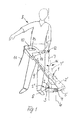
- eine schematische Darstellung des neuen Freischneidegerätes, das von einem Benutzer in der Arbeitsstellung gehalten wird,
- Fig. 2
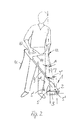
- eine Darstellung ähnlich Fig. 1, jedoch während des Schneidbetriebes,
- Fig. 3
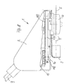
- eine vergrößerte Darstellung eines Längsschnittes durch ein Freischneidegerät nach der Erfindung in einer von dem Freischneidegerät nach den Fig. 1 und 2 etwas abweichenden Form,
- Fig. 4
- eine vergrößerte Seitenansicht eines Freischneidegerätes nach der Erfindung in einer anderen Ausführungsform, und
- Fig. 5
- eine vergrößerte Seitenansicht eines Freischneidegerätes in einer weiteren Ausführungsform, die der Form nach Fig. 1 und 2 nahe kommt.
- Fig. 1
- 1 shows a schematic representation of the new brush cutter which is held in the working position by a user,
- Fig. 2
- 1, but during the cutting operation,
- Fig. 3
- 2 shows an enlarged illustration of a longitudinal section through a brush cutter according to the invention in a form slightly different from the brush cutter according to FIGS. 1 and 2,
- Fig. 4
- an enlarged side view of a brush cutter according to the invention in another embodiment, and
- Fig. 5
- an enlarged side view of a brush cutter in a further embodiment, which comes close to the shape of FIGS. 1 and 2.
Die Fig. 1 zeigt zunächst, dass das Freischneidegerät 1 gemäß der Erfindung
aus einem Gehäuse 2 mit einem integrierten Schutzgehäuse 3
besteht, welches einen von einem Schneidkopf 4 in Rotation versetzten
Schneidfaden 5 umgibt. Der Schneidfaden 5 und der Schneidkopf 4 rotieren
um eine vertikale Achse 6, welches im vorliegenden Fall auch die
Achse der Schneidkopfwelle ist. Der Schneidkopf 4 bzw. dessen auf der
Achse 6 liegende Welle, wird dabei in ähnlicher Weise, wie das später
anhand von Fig. 3 erläutert werden wird, über ein Getriebe, beispielsweise
in Form eines Riemens, insbesondere eines Zahnriemens, von
einem Elektromotor angetrieben, dessen Abtriebswelle parallel zur Achse
6 verläuft und mit der Achse 7 zusammenfällt, die, wie Fig. 1 erkennen
lässt, ganz nahe am Benutzer 8 liegt und in etwa durch den Bereich
der linken Schulter des Benutzers 8 verläuft.Fig. 1 shows first that the
Das Freischneidegerät 1 besitzt eine Halte- und Führungseinrichtung in
Form einer Stange 9, die am Gehäuse 2 befestigt ist und am oberen
Ende mit einem Handgriff als Führungs- und Betätigungsgriff 10 versehen
ist, an dem sich auch ein Schalter zur Zu- und Abschaltung der Energieversorgung
des Elektromotors innerhalb des Gehäuses 2 befindet.
Die Energieversorgung erfolgt dabei in bekannter Weise über ein Stromführungskabel
11, wobei ein weiteres Kabel von dem nicht gezeigten
Schalter im Bereich des Handgriffes 10 aus innerhalb der hohlen Stange
9 zum Elektromotor geführt ist.The
Zwischen dem Haltegriff 10 und dem Gehäuse 2 befindet sich an der
Stange 9 ein seitlich abragender Arm 14 mit einem weiteren Handgriff
12, der gemäß Fig. 1 zum Tragen des Freischneidegerätes 1 und zum
Halten während der Bearbeitung dient und von einer Hand der Bedienungsperson
übergriffen wird. Es ist zu erkennen, dass die senkrechte
Achse 7, die mit der Achse des in Fig. 1 nicht gezeigten Elektromotors
zusammenfällt, durch den Bereich der Position der Hand am Handgriff
12 führt, so dass dadurch der Schwerpunkt des Gerätes 1, der sich aus
den Gewichten des Schutzgehäuses 3, des Schneidkopfes 4, des - nicht
gezeigten - Elektromotors der Stange 9 mit dem abragenden Arm und
den beiden Handgriffen zusammensetzt, auf der Achse 7 liegt. Dies
deshalb, weil das Gewicht des Elektromotors, der auf dieser Achse 7
liegt, wesentlich größer als das Gewicht des Schneidkopfes 4 und des in
der Regel aus Kunststoff hergestellten Gehäuses 2, des Schutzgehäuses
3 oder anderer Teile ist, so dass die Lage des Elektromotors im wesentlichen
auch verantwortlich ist für die Lage des Gesamtschwerpunktes.
Die Konstruktion des neuen Freischneidegerätes ist nun so gewählt,
was auch noch anhand von Fig. 3 bis 5 deutlich werden wird, dass der
Gesamtschwerpunkt des Freischneidegerätes 1 in etwa unterhalb des
Handgriffes 12 auf der Achse 7 liegt. Das Gewicht des Gerätes kann
durch diese Ausgestaltung, bei der der Handgriff 12 entsprechend angeordnet
wurde, mit hängendem Arm vom Benutzer 8 aufgenommen
werden. Dies gewährleistet eine weitgehend ohne Kraftanstrengung verlaufende
Handhabung während der Benutzung.Between the
Die Fig. 2 erläutert, dass sich diese Tragfunktion des neuen Gerätes 1
während der Benutzung des Gerätes nicht verändert. Der linke Arm
bleibt am Zusatzgriff und nimmt daher bei der Benutzung das Gewicht
des Freischneidegerätes 1 auf. Die rechte Hand wird zum Betätigungsgriff
13 geführt.2 explains that this supporting function of the
Die Fig. 1 und 2 zeigen, dass der Handgriff 12 an dem seitlich von der
Stange 9 in Richtung zur Achse 7 abragenden Arm 14 angeordnet ist,
der wiederum Teil des bügelartig mit dem Arm 14 verbundenen Handgriffes
10 ist. Dieser Handgriff 12 bildet den Schwenkpunkt für das gesamte
Gerät. Fig. 1 zeigt, dass der Schwerpunkt S des Gesamtgerätes
so gewählt werden kann, dass er - auf der Achse 7 - senkrecht unter
dem Handgriff 12 liegt. Er kann aber auch so gewählt werden, dass das
Gerät im Gegenuhrzeigersinn auspendelt, wenn es lediglich am Handgriff
12 gehalten wird. In diesem Fall ist der Schwerpunkt S' für das Gesamtgerät
vom Schwerpunkt S der ursprünglichen Bauart gesehen weiter
nach links verlagert, was durch entsprechende Gewichtsverteilung
des gesamten Gerätes erreicht werden kann und was schematisch in
Fig. 1 eingezeichnet ist. Wird in diesem Fall das Gesamtgerät, dessen
Schwerpunkt S' also anders gelegt ist als der ursprüngliche Schwerpunkt
S, am Handgerät 12 gemäß Fig. 1 gehalten, so wird sich das Gehäuse
des Gerätes in die Stellung 2' verschwenken, in der der Schwerpunkt
S' nunmehr die Lage S einnimmt. Eine solche Schwerpunktlage S'
des Gesamtgerätes, bei welcher das Gerät 1 abweichend von der
durchgezogenen Stellung in Fig. 1 bei einhändigem Halten mit seinem
Schneidkopf 4 leicht vom Benutzer 8 weg pendelt, ist eine durchaus bevorzugte
Anordnung. In der in Fig. 2 dargestellten Arbeitsstellung kann
nämlich dann vom Benutzer mit seiner zweiten Hand zusätzlich ein Gewichtsanteil
des Geräts aufgenommen werden. Zum einen wird dadurch
der hängende Arm - also der linke Arm des dargestellten Benutzers 8-geringfügig
von Gewicht entlastet, zum anderen ist der am oberen Griffteil
10 und am Bedienschalter 12 ansetzende Bedienarm des Benutzers
immer leicht auf Zug beansprucht (da er das Gesamtgerät um den
Schwenkpunkt am Handgriff 12 im Uhrzeigersinn verschwenkt) und
macht bei Betrieb des Gerätes stets auftretende Schwenkbewegungen zum Anpassen
an gegebene Untergründe oder sonstige Schneidsituationen, im
wesentlichen keine Lastwechsel zwischen ziehender und drückender
Kraftbeaufschlagung durch, was ein gleichmäßigeres Arbeiten begünstigt.
Natürlich wäre es auch möglich, den Schwerpunkt in der Ausgangslage
rechts vom ursprünglichen Schwerpunkt S anzuordnen, so dass
dann das Gerät beim Halten nach Fig. 1 um den Schwenkpunkt beim
Handgriff 12 im Uhrzeigersinn gegenüber der durchgezogenen Stellung
verschwenkt wird. Bei einer solchen Anordnung müsste eine gewisse
Druckkraft während des Betriebes von der Bedienungsperson ausgeübt
werden.1 and 2 show that the
Es hat sich als zweckmäßig erwiesen, den Gesamtschwerpunkt S des
Gerätes in der ausgezogenen Darstellung nach Fig. 1 bei senkrecht stehender
Schneidachse 6 und senkrecht stehender Achse 7 des Antriebsmotor
maximal um einen Winkel α von 30°, vorzugsweise aber
maximal 20°, zum Benutzer 8 hinweisend, also in der Lage S' anzuordnen.
Bei einer solchen Ausgestaltung pendelt sich das Gerät 1 mit seinem
Gehäuse in die Lage 2' und mit seiner Motorachse in die Lage 7'
aus, die vom Benutzer 8 weggerichtet ist. Es können dann die vorher
erwähnten Vorteile erreicht werden. Bei einer Verlagerung des Schwerpunktes,
wie in Fig. 2 mit S" angedeutet, vom Benutzer weg und bei einer
demzufolge eintretenden Auspendelung des Gerätes um den Handgriff
12 zum Benutzer hin, sollten jedoch nur Winkel β auftreten, die maximal
15°, vorzugsweise maximal 10° betragen, wenn die angestrebte
leichte Bearbeitungsmöglichkeit gegeben sein soll.It has proven to be useful to focus on the overall S
Device in the solid representation of FIG. 1 with vertical
Cutting axis 6 and
Das Freischneidegerät 1 kann, wie Fig. 3 zeigt, in einer besonders vorteilhaften
Ausführungsform mit einem Elektromotor 15 versehen sein,
der im Gehäuse 2' des Gerätes, das natürlich auch in der in den Fig. 1
und 2 gezeigten Form ausgebildet sein kann, integriert ist. Die Motorwelle
16 ist gegenüber der Schneidkopfwelle 17 parallel und seitlich versetzt.
Motorwelle 16 und Schneidkopfwelle 17 tragen jeweils ein Zahnrad
18 bzw. 19, wobei diese Zahnräder 18 und 19 zur Verringerung der
Drehzahl unterschiedliche Zahnzahlen aufweisen. Das Zahnrad 19 der
Schneidkopfwelle 17 besitzt eine größere Zahnzahl. Diese beiden Zahnräder
18 und 19 sind durch einen Zahnriemen 20 untereinander verbunden,
der die Motorleistung von der Motorwelle 16 aus auf die Schneidkopfwelle
17 überträgt. Auf der Schneidkopfwelle 17 ist der Schneidkopf
4 befestigt, der mit dem Schneidfaden 5 versehen ist. Der Schneidkopf 4
dreht sich im Betrieb mit einer gegenüber der Motorwelle 16 reduzierten
Drehzahl. Beispielsweise liegt die Motordrehzahl bei mindestens 20 000
Umdrehungen pro Minute und die Schneidkopfwellendrehzahl bei lediglich
8000 bis 11.000 Umdrehungen pro Minute. Der Elektromotor 15 ist
gegenüber der Position der Schneidkopfwelle 17 vom Schneidbereich
weg nach hinten - zu der in Fig. 3 nicht gezeigten Bedienungsperson-versetzt
angeordnet, so dass keine Beeinträchtigung bei der Handhabung
des Geräts auftritt. Bei der skizzierten Anordnung ist ferner vorteilhaft,
dass eine sehr stabile Lagerung der Schneidkopfwelle 17 in
Schneidkopflagern 21 möglich ist, ohne dass die Bauhöhe ungebührlich
erhöht werden muss. Belastungsschläge auf den Schneidfaden bzw. die
Schneidkopfwelle 17 werden über den Zahnriemen 20 nur stark gedämpft
auf die Motorwelle 16 des Elektromotors 15 übertragen. Das
Schneidkopflager 21 und der Motor 15 sind in dem gemeinsamen Gehäuse
2' untergebracht, welches auch eine Befestigungsaufnahme 22
für eine Gerätetragstange 9' umfasst. Wie vorher bereits angedeutet
wurde, kann diese Befestigungsaufnahme 22 auch in der Weise schräg
am Gehäuse 2' angeordnet sein, wie das in den Fig. 1 und 2 gezeigt ist.The
Die Fig. 3 zeigt auch den Rotationsbereich des Schneidfadens 5 innerhalb
des Schutzgehäuses 3. Es ist zu erkennen, dass das Schutzgehäuse
3 bis in den Bereich unterhalb des Elektromotors 15 reicht und
dass der Schneidfaden 5 bei seiner Rotation im Bereich unterhalb des
Elektromotors 15 umläuft. Dies ist durch das Bezugszeichen 5' angedeutet.
Die Motorwelle 16, beim gezeigten Ausführungsbeispiel aber
auch der gesamte Elektromotor 15, liegen dabei im Rotationsbereich
des Schneidfadens 5, wobei beim Ausführungsbeispiel der Motor 15
auch so angeordnet und ausgebildet ist, dass er das Schutzgehäuse 3
nicht nach außen überragt. Eine solche Ausgestaltung ergibt daher ein
kompaktes Fadenschneidgerät, dessen Umfang nicht größer ist, als der
eines Fadenschneidgerätes, das über eine flexible Welle durch eine
Führungsstange hindurch von einem Motor, beispielsweise von einem
mit Kraftstoff betriebenen Motor, angetrieben ist, der sich am oberen
Ende der Halte- und Führungsstange befindet. Der Raumbedarf für das
neue Freischneidegerät kann daher sehr gering, insbesondere nicht
oder nicht wesentlich größer als bei vergleichbaren Geräten herkömmlichen
Aufbaus, gehalten werden.3 also shows the range of rotation of the cutting
Wie aber bei der Betrachtung von Fig. 3 auch deutlich wird, liegt der Gesamtschwerpunkt
des Fadenschneidgeräts 1 in jedem Fall im Bereich
der Achse 7, weil sich hier der relativ schwere Elektromotor befindet,
dessen Antriebskraft über den Zahnriemen 20 zu der seitlich versetzt
angeordneten Schneidkopfwelle 17 übertragen wird. Diese Ausgestaltung
ermöglicht daher die anhand der Fig. 1 und 2 beschriebene vorteilhafte
Handhabung.However, as is also clear when looking at FIG. 3, the overall focus is on
of the
Die Fig. 4 zeigt eine Ausgestaltung, bei der das Gehäuse 2 relativ flach
ausgebildet ist. Auch hier sind jedoch die Achsen 7 und 17 parallel zueinander
so versetzt, dass der Gesamtschwerpunkt des Freischneidegerätes
in etwa in der vertikalen Achse 7 liegt. Auch in diesem Fall ist das
Gehäuse des Elektromotors 15 in das Gehäuse 2 des Gerätes integriert,
und das Schutzgehäuse 3 reicht bis in den Bereich unterhalb des Elektromotors
15, der also auch hier dieses Schutzgehäuse 3 seitlich nicht
überragt und im Rotationsbereich des Schneidfadens 5 liegt. Die in Fig.
4 gezeigte Ausführungsform weist den Vorteil auf, dass die vom Benutzer
abgewandte Seite des Gehäuses 2 sehr flach ist, so dass damit ohne
Probleme seitlich auch unter Hecken oder dergleichen eine Mähbearbeitung
möglich ist. Die Führungs- und Haltestange 9" wird hier in einer
Befestigungsmuffe 22' gehalten, die mit dem Gehäuseteil 2a fluchtet,
in dem der Elektromotor 15 angebracht ist. Auch bei dieser Ausführungsform
ist an der Führungsstange 9" der weitere Handgriff 12 in der
in den Fig. 1 und 2 gezeigten Weise so angebracht, dass er auf der
Achse 7 liegt.4 shows an embodiment in which the
Fig. 5 schließlich zeigt ein Gehäuse 2, das in seiner Form jenem der Fig.
1 und 2 recht nahe kommt. Hier ist der Elektromotor 15 an seiner Abtriebswelle
16 mit einer Riemenscheibe 118 versehen, die einen Riemen
120 aufnimmt, der die Motorleistung auf eine weitere Riemenscheibe
119 überträgt, die auf der Antriebsachse 17 des Schneidkopfes 4 befestigt
ist, der auch hier mit einem Schneidfaden 5 versehen ist. Die Drehachse
16 des Motors 15 liegt auch hier im Rotationsbereich des
Schneidfadens 5. Denkbar wäre aber auch, dass sie bis zu 30 % des
Abstandes zwischen Drehachse 16 und Antriebsachse 17 des Schneidkopfes
über den Rotationsbereich des Schneidwerkzeuges hinausragt.FIG. 5 finally shows a
Die in den Fig. 3 bis 5 beschriebenen Ausführungsbeispiele sehen als
Bearbeitungswerkzeug einen Schneidfaden 5 vor. Denkbar wäre es aber
auch, den Schneidkopf 4 mit einer Schneidscheibe zu bestücken, wenn
dies zweckmäßig erscheinen sollte. Die Ausführungsform mit einem
Schneidfaden allerdings gewährleistet, wegen des geringen Fadengewichts,
in sehr viel einfacherer Weise, dass der Gesamtschwerpunkt des
Gerätes 1 auch in etwa mit der Achse 7 zusammenfällt, die in etwa auch
der Motorachse entspricht.The exemplary embodiments described in FIGS. 3 to 5 see as
Machining tool a cutting
Claims (5)
dadurch gekennzeichnet, dass
zwischen Schutzgehäuse (3) und einem oberen Handgriff (10) ein seitlich abragender weiterer Handgriff (12) angeordnet ist und die Motorachse (7) parallel zu der Achse (6) der Schneidewelle so nach hinten zum Benutzer hin versetzt ist, dass der Schwerpunkt (5) des Gesamtgerätes (1) in der Arbeitsstellung der Halte- und Führungseinrichtung, in der die Rotationsachse (6) des Schneidwerkzeuges vertikal verläuft, etwa senkrecht unterhalb des weiteren Handgriffes (12) liegt.Brush cutter, in particular thread cutter, with a rotating cutting head with a cutting tool and a protective housing (3) surrounding it, with a gear element (20) between the output shaft of a motor and the drive shaft of the cutting head and with a holding and guiding device (9),
characterized in that
A laterally protruding further handle (12) is arranged between the protective housing (3) and an upper handle (10) and the motor axis (7) is offset parallel to the axis (6) of the cutting shaft towards the user in such a way that the center of gravity ( 5) of the entire device (1) in the working position of the holding and guiding device, in which the axis of rotation (6) of the cutting tool runs vertically, approximately perpendicularly below the further handle (12).
Applications Claiming Priority (2)
| Application Number | Priority Date | Filing Date | Title |
|---|---|---|---|
| DE2000138903 DE10038903A1 (en) | 2000-08-09 | 2000-08-09 | Brush cutter powered by an electric motor |
| DE10038903 | 2000-08-09 |
Publications (1)
| Publication Number | Publication Date |
|---|---|
| EP1179291A1 true EP1179291A1 (en) | 2002-02-13 |
Family
ID=7651876
Family Applications (1)
| Application Number | Title | Priority Date | Filing Date |
|---|---|---|---|
| EP01118779A Withdrawn EP1179291A1 (en) | 2000-08-09 | 2001-08-09 | Portable mower |
Country Status (2)
| Country | Link |
|---|---|
| EP (1) | EP1179291A1 (en) |
| DE (1) | DE10038903A1 (en) |
Cited By (3)
| Publication number | Priority date | Publication date | Assignee | Title |
|---|---|---|---|---|
| EP1508267A1 (en) * | 2003-08-19 | 2005-02-23 | Arnetoli Motor Di Arnetoli Fabrizio | Device for cutting vegetation or for other applications, with electric motor and reducing gear |
| WO2013032373A1 (en) | 2011-08-26 | 2013-03-07 | Husqvarna Ab | Battery powered hand held cutting tool |
| EP2952083A4 (en) * | 2013-02-01 | 2016-11-09 | Makita Corp | Mower |
Citations (5)
| Publication number | Priority date | Publication date | Assignee | Title |
|---|---|---|---|---|
| US4202094A (en) * | 1977-07-05 | 1980-05-13 | Irene Kalmar | Rotary machine attachment |
| US4286675A (en) * | 1979-06-25 | 1981-09-01 | Beaird-Poulan Division Of Emerson Electric Co. | Narrow profile power handle for line trimmer and the like |
| WO1992015193A1 (en) * | 1991-03-01 | 1992-09-17 | Inertia Dynamics Corporation | Battery powered line trimmer |
| EP0515909A1 (en) * | 1991-05-27 | 1992-12-02 | WOLF-Geräte GmbH Vertriebsgesellschaft KG | Line trimmer |
| EP0753245A1 (en) * | 1995-07-13 | 1997-01-15 | Valex S.P.A. | Portable gardening implement with adjustable safety handgrip |
Family Cites Families (1)
| Publication number | Priority date | Publication date | Assignee | Title |
|---|---|---|---|---|
| DE3629039C2 (en) * | 1986-08-27 | 1994-10-20 | Stihl Maschf Andreas | Portable work tool |
-
2000
- 2000-08-09 DE DE2000138903 patent/DE10038903A1/en not_active Withdrawn
-
2001
- 2001-08-09 EP EP01118779A patent/EP1179291A1/en not_active Withdrawn
Patent Citations (5)
| Publication number | Priority date | Publication date | Assignee | Title |
|---|---|---|---|---|
| US4202094A (en) * | 1977-07-05 | 1980-05-13 | Irene Kalmar | Rotary machine attachment |
| US4286675A (en) * | 1979-06-25 | 1981-09-01 | Beaird-Poulan Division Of Emerson Electric Co. | Narrow profile power handle for line trimmer and the like |
| WO1992015193A1 (en) * | 1991-03-01 | 1992-09-17 | Inertia Dynamics Corporation | Battery powered line trimmer |
| EP0515909A1 (en) * | 1991-05-27 | 1992-12-02 | WOLF-Geräte GmbH Vertriebsgesellschaft KG | Line trimmer |
| EP0753245A1 (en) * | 1995-07-13 | 1997-01-15 | Valex S.P.A. | Portable gardening implement with adjustable safety handgrip |
Cited By (8)
| Publication number | Priority date | Publication date | Assignee | Title |
|---|---|---|---|---|
| EP1508267A1 (en) * | 2003-08-19 | 2005-02-23 | Arnetoli Motor Di Arnetoli Fabrizio | Device for cutting vegetation or for other applications, with electric motor and reducing gear |
| WO2013032373A1 (en) | 2011-08-26 | 2013-03-07 | Husqvarna Ab | Battery powered hand held cutting tool |
| CN103763912A (en) * | 2011-08-26 | 2014-04-30 | 胡斯华纳有限公司 | Battery powered hand held cutting tool |
| EP2747543A1 (en) * | 2011-08-26 | 2014-07-02 | Husqvarna AB | Battery powered hand held cutting tool |
| EP2747543A4 (en) * | 2011-08-26 | 2015-04-22 | Husqvarna Ab | Battery powered hand held cutting tool |
| EP2952083A4 (en) * | 2013-02-01 | 2016-11-09 | Makita Corp | Mower |
| EP2952083B1 (en) | 2013-02-01 | 2020-03-25 | Makita Corporation | Brush cutter |
| USRE48068E1 (en) | 2013-02-01 | 2020-06-30 | Makita Corporation | Brush cutter |
Also Published As
| Publication number | Publication date |
|---|---|
| DE10038903A1 (en) | 2002-02-21 |
Similar Documents
| Publication | Publication Date | Title |
|---|---|---|
| DE3629039C2 (en) | Portable work tool | |
| DE60106085T2 (en) | PORTABLE SCISSORS WITH MOTOR DRIVE | |
| DE102006041947B4 (en) | Vibration-absorbing coupling and portable bush cutter equipped with the vibration-absorbing coupling | |
| DE19619081B4 (en) | Cutting head for a pruner | |
| DE4013512A1 (en) | SWITCHING DEVICE FOR SWITCHING A POWERED TOOL | |
| DE3518984A1 (en) | BALANCED ORBIT SANDER | |
| DE19919385A1 (en) | Strimmer | |
| DE2551842A1 (en) | ELECTRIC MOTOR DRIVE UNIT, IN PARTICULAR FOR KITCHEN MACHINES OR THE LIKE. | |
| DE2217351A1 (en) | ELECTRIC POWERED LAWN MOWER | |
| EP2556922B1 (en) | Power tool | |
| DE102006061625A1 (en) | Electric hand tool e.g. drill hammer, has motor connectable with spindle and/or sliding tool over transmission and pivotable around axis, where middle axle of shaft of transmission or central axle of drive shaft forms axis | |
| EP1428625B1 (en) | Oscillating drive | |
| EP0868264B1 (en) | Electric hand tool | |
| DE19833790C1 (en) | Agitating pole for harvesting fruit from trees | |
| EP1179291A1 (en) | Portable mower | |
| EP3272207A1 (en) | Working device with partial housings connected via a swivel joint | |
| DE102013210391A1 (en) | power tool | |
| EP1295520B1 (en) | Rotary harrow with improved rotor driving | |
| EP1564424B1 (en) | Device for lawn, garden and field maintenance | |
| DE19954026B4 (en) | Harrow | |
| DE1299579B (en) | Transportable, motor-driven rotary impact device | |
| DE1582863A1 (en) | Cutting device | |
| DE102006051153B4 (en) | Joint cutting device with oscillating cutting element | |
| EP1180320B1 (en) | Lawn tractor | |
| DE4319409A1 (en) | Blade drive for hand-guided motor-driven mower - has swivel mounted angular bar between eccentric drive and cutter entrainment member to adapt freely to uneven ground. |
Legal Events
| Date | Code | Title | Description |
|---|---|---|---|
| PUAI | Public reference made under article 153(3) epc to a published international application that has entered the european phase |
Free format text: ORIGINAL CODE: 0009012 |
|
| AK | Designated contracting states |
Kind code of ref document: A1 Designated state(s): AT BE CH CY DE DK ES FI FR GB GR IE IT LI LU MC NL PT SE TR |
|
| AX | Request for extension of the european patent |
Free format text: AL;LT;LV;MK;RO;SI |
|
| 17P | Request for examination filed |
Effective date: 20020615 |
|
| AKX | Designation fees paid |
Free format text: AT BE CH CY DE DK ES FI FR GB GR IE IT LI LU MC NL PT SE TR |
|
| AXX | Extension fees paid |
Free format text: RO PAYMENT 20020615;SI PAYMENT 20020615 |
|
| RAP1 | Party data changed (applicant data changed or rights of an application transferred) |
Owner name: GARDENA MANUFACTURING GMBH |
|
| STAA | Information on the status of an ep patent application or granted ep patent |
Free format text: STATUS: THE APPLICATION IS DEEMED TO BE WITHDRAWN |
|
| 18D | Application deemed to be withdrawn |
Effective date: 20050301 |