EP1179153B1 - Flexible schlauchleitung, insbesondere unter druckeinwirkung einer verformung unterliegende hochdruckschlauchleitung - Google Patents
Flexible schlauchleitung, insbesondere unter druckeinwirkung einer verformung unterliegende hochdruckschlauchleitung Download PDFInfo
- Publication number
- EP1179153B1 EP1179153B1 EP00927168A EP00927168A EP1179153B1 EP 1179153 B1 EP1179153 B1 EP 1179153B1 EP 00927168 A EP00927168 A EP 00927168A EP 00927168 A EP00927168 A EP 00927168A EP 1179153 B1 EP1179153 B1 EP 1179153B1
- Authority
- EP
- European Patent Office
- Prior art keywords
- inner layer
- hose line
- layer
- flexible hose
- reinforcing layer
- Prior art date
- Legal status (The legal status is an assumption and is not a legal conclusion. Google has not performed a legal analysis and makes no representation as to the accuracy of the status listed.)
- Expired - Lifetime
Links
- 238000000034 method Methods 0.000 title claims abstract description 5
- 230000003014 reinforcing effect Effects 0.000 claims abstract description 28
- 238000006073 displacement reaction Methods 0.000 claims description 3
- 229920001971 elastomer Polymers 0.000 claims description 3
- 239000000806 elastomer Substances 0.000 claims description 3
- 238000004519 manufacturing process Methods 0.000 claims description 2
- 239000007769 metal material Substances 0.000 claims description 2
- 229920002725 thermoplastic elastomer Polymers 0.000 claims description 2
- 239000012815 thermoplastic material Substances 0.000 claims 1
- 230000002787 reinforcement Effects 0.000 description 18
- 239000000463 material Substances 0.000 description 6
- 239000002184 metal Substances 0.000 description 4
- 239000002131 composite material Substances 0.000 description 2
- 239000000945 filler Substances 0.000 description 2
- 239000012530 fluid Substances 0.000 description 2
- 230000036316 preload Effects 0.000 description 2
- 230000001681 protective effect Effects 0.000 description 2
- 238000010521 absorption reaction Methods 0.000 description 1
- 238000006243 chemical reaction Methods 0.000 description 1
- 239000004744 fabric Substances 0.000 description 1
- 230000002349 favourable effect Effects 0.000 description 1
- 238000007373 indentation Methods 0.000 description 1
- 230000001404 mediated effect Effects 0.000 description 1
- 230000000149 penetrating effect Effects 0.000 description 1
- 230000002035 prolonged effect Effects 0.000 description 1
- 239000012858 resilient material Substances 0.000 description 1
- 239000004753 textile Substances 0.000 description 1
- 229920001169 thermoplastic Polymers 0.000 description 1
- 239000004416 thermosoftening plastic Substances 0.000 description 1
- 230000007704 transition Effects 0.000 description 1
Images

Classifications
-
- F—MECHANICAL ENGINEERING; LIGHTING; HEATING; WEAPONS; BLASTING
- F16—ENGINEERING ELEMENTS AND UNITS; GENERAL MEASURES FOR PRODUCING AND MAINTAINING EFFECTIVE FUNCTIONING OF MACHINES OR INSTALLATIONS; THERMAL INSULATION IN GENERAL
- F16L—PIPES; JOINTS OR FITTINGS FOR PIPES; SUPPORTS FOR PIPES, CABLES OR PROTECTIVE TUBING; MEANS FOR THERMAL INSULATION IN GENERAL
- F16L11/00—Hoses, i.e. flexible pipes
- F16L11/14—Hoses, i.e. flexible pipes made of rigid material, e.g. metal or hard plastics
- F16L11/15—Hoses, i.e. flexible pipes made of rigid material, e.g. metal or hard plastics corrugated
-
- F—MECHANICAL ENGINEERING; LIGHTING; HEATING; WEAPONS; BLASTING
- F16—ENGINEERING ELEMENTS AND UNITS; GENERAL MEASURES FOR PRODUCING AND MAINTAINING EFFECTIVE FUNCTIONING OF MACHINES OR INSTALLATIONS; THERMAL INSULATION IN GENERAL
- F16L—PIPES; JOINTS OR FITTINGS FOR PIPES; SUPPORTS FOR PIPES, CABLES OR PROTECTIVE TUBING; MEANS FOR THERMAL INSULATION IN GENERAL
- F16L27/00—Adjustable joints; Joints allowing movement
- F16L27/10—Adjustable joints; Joints allowing movement comprising a flexible connection only
- F16L27/107—Adjustable joints; Joints allowing movement comprising a flexible connection only the ends of the pipe being interconnected by a flexible sleeve
- F16L27/11—Adjustable joints; Joints allowing movement comprising a flexible connection only the ends of the pipe being interconnected by a flexible sleeve the sleeve having the form of a bellows with multiple corrugations
- F16L27/111—Adjustable joints; Joints allowing movement comprising a flexible connection only the ends of the pipe being interconnected by a flexible sleeve the sleeve having the form of a bellows with multiple corrugations the bellows being reinforced
Definitions
- the invention relates to a flexible hose line, in particular under pressure a high pressure hose line subject to deformation, preferably for changing pressure loads, and a method for producing such Hose lines according to the preamble of claims 1 and 12.
- GB-A-1506776 is a flexible, tubular structure for forwarding of a fluid known.
- the structure consists of an inner, tubular, with corrugations in the form of depressions and elevations, provided layer, which from a deformable material and is impermeable to the fluid, one tubular filler layer made of a deformable material with which the recesses fill up and cover the elevations with a given material thickness and an outer tubular reinforcement layer around the fill layer, which consists of groups of interwoven textile fabrics or Metal wires is built up.
- the reinforcing layer is in the axial direction with the underlying filler layer firmly connected in such a way that a shift is limited in the axial direction between these two layers to the extent that Displacements in the axial direction, causing the two layers to slide would lead against each other, is avoided, but a slight shift is possible.
- the transition area between the metal hose and Connection element made more resilient.
- the invention has for its object to develop a hose line can be exposed to high pressures and in particular a pressure change load withstands over a comparatively long period of time.
- an inner layer which is at least one has profiling that can be elastically loaded in the longitudinal direction of the hose, through a reinforcement layer, which is used to hold the hose in the longitudinal direction acting tensile forces is formed by a between the inner layer and the Reinforcement layer arranged, the compensation of the relative movement of this Layers to each other and the radial support of the inner layer on the reinforcing layer serving compensation area and through connection areas of the inner layer with the reinforcement layer, the inner layer of an axially is formed elastically pretensionable body, the component in the pretensioned state the hose line is.
- the preload is expediently chosen in such a way that that even with the greatest possible pressure amplitude, a certain preload remains to the material fatigue even with prolonged use and high pulse change rates to keep low.
- the invention is associated with the advantage that with extensive flexibility Hose line this a high pressure, in particular one Pressure fluctuations can also be exposed to large amplitudes.
- a Such a possibility results from the inherently high flexibility of the inner layer due to the reinforcement layer in connection with the compensation zone depending on pressure is reduced.
- the compensation zone serves the largely uniform absorption and distribution of the inner layer outgoing forces.
- each connection area is more direct positive and / or non-positive contact of the inner layer with the reinforcing layer educated.
- the profiling of the inner layer is similar to corrugated pipe educated.
- the inner layer can also be a corrugated pipe act that allows a change in length with only low material stress.
- the inner layer can be highly gas impermeable be formed, which is preferably achieved in which the inner layer from a metallic material.
- the reinforcement layer is formed from a braid in which the threads of the braid have an axial orientation have and the preferred braid angle ⁇ , based on the longitudinal axis of the hose, Does not exceed 50 ° and is expedient in the range between 35 ° and 45 ° lies.
- the compensation zone is preferably made of one Elastomer, a thermoplastic elastomer or a thermoplastic formed. Another favorable distribution of the forces introduced into the overall system is achieved by at least the compensation zone in the profiling of the inner layer immersed in or filled in the connection areas.
- a method according to the invention for producing a flexible hose line is that the inner layer and / or the reinforcing layer with a the respective layer adhering compensation zone that the interior layer and the reinforcement layer by relative displacement in the required Position are brought to each other, the inner layer in the longitudinal direction of the Hose line is pre-tensioned before connecting the inner layer and Reinforcement layer in the area of the hose fittings.
- a non-positive and / or positive connection between the inner layer and the reinforcing layer can be expediently applied to it by radial force the reinforcing layer enveloping component are produced.
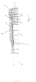
- the hose shown in Figure 1 in its end region consists of a metallic inner layer 1, an elastomeric compensation zone 2, one as Mesh reinforcement layer 3 and an elastomer Outer layer 4.
- the corrugated tube-shaped inner layer 1 is rigid with the hose end a, having a sawtooth-shaped contour on the outer circumference Connection piece 5 connected in a hollow cylindrical connecting piece 6 passes.
- the connector 5 and the connector 5 adjacent Area 7 of the inner layer 1 and those adjoining it radially outwards Sections of the compensation zone 2, the reinforcement layer 3 and the Outer layer 4 are surrounded by a socket 8.
- the socket 8 is deformed as a result of radial force such that on the connector 5 a direct positive and / or non-positive contact Inner layer 1 is made with the reinforcing layer 3 and a Connection area 9 is formed, from which the compensation zone 2 as a result of radial force has been displaced. Furthermore, there is one Form fit between the inner layer 1 and in the recesses of the Profiling of the inner layer 1 penetrating segments 10 of the compensation zone Second
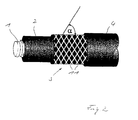
- the braid of the reinforcement layer 3 is made of threads or thread groups 11 constructed, which - as can be seen from Figure 2 - axially oriented, d. H. , in Hose longitudinal direction are resilient and at a braid angle ⁇ of preferably run 35 ° to 45 °.
- connection area 9 As shown in FIG. 3, a support ring 12 can be used be provided over which the radial distance of the reinforcing layer 3 in Connection area 9 is set.
- a support ring 12 with a suitable choice of material in the form Increase connection area 9 by the braid of the reinforcement layer 3 is at least partially pressed radially into the support ring 12 and therefore axially is resilient.
- the corrugated tube-shaped ones are formed metallic inner layer 1 and - from compensation zone 2, reinforcement layer 3 and outer layer 4 formed - composite body relative to each other in position brought so that the inner layer 1 is enveloped by the composite body.
- the sockets 8 in the connection areas 9 of the inner layer 1 and Reinforcement layer 3 is arranged, after which the inner layer 1 is axially prestressed and in the prestressed state by radial, if necessary also by axial, Force applied to the sockets 8 connected to the reinforcing layer 3 and is thus fixed.
Landscapes
- Engineering & Computer Science (AREA)
- General Engineering & Computer Science (AREA)
- Mechanical Engineering (AREA)
- Rigid Pipes And Flexible Pipes (AREA)
- Laminated Bodies (AREA)
- Pipe Accessories (AREA)
Description
- Fig. 1
- einen Schlauchleitungsbereich, teilweise im Schnitt,
- Fig. 2
- einen Schlauchabschnitt mit freigelegter Verstärkungsschicht und
- Fig. 3
- einen Schlauchleitungsbereich mit gegenüber Figur 1 geändertem Verbindungsbereich von Innenschicht und Verstärkungsschicht.
Claims (13)
- Flexible Schlauchleitung, insbesondere unter Druckeinwirkung einer Verformung unterliegende Hochdruckschlauchleitung, vorzugsweise für wechselnde Druckbeanspruchung, bestehend aus einer Innenschicht (1), die eine zumindest in Schlauchlängsrichtung elastisch beanspruchbare Profilierung aufweist, aus einer Verstärkungsschicht (3), die zur Aufnahme von in Schlauchlängsrichtung wirkenden Zugkräften ausgebildet ist, aus einer zwischen der Innenschicht (1) und der Verstärkungsschicht (3) angeordneten, dem Ausgleich der Relativbewegung dieser Schichten zueinander und der radialen Abstützung der Innenschicht (1) auf der Verstärkungsschicht (3) dienenden Ausgleichszone (2) und aus Verbindungsbereichen (9) der Innenschicht (1) mit der Verstärkungsschicht (3), dadurch gekennzeichnet, dass die Innenschicht (1) von einem axial elastisch vorspannbaren Körper gebildet ist, der in vorgespanntem Zustand Bestandteil der Schlauchleitung ist.
- Flexible Schlauchleitung nach Anspruch 1, dadurch gekennzeichnet, dass jeder Verbindungsbereich (9) als direkter form- und/oder kraftschlüssiger Kontakt der Innenschicht (1) mit der Verstärkungsschicht (3) ausgebildet ist.
- Flexible Schlauchleitung nach Anspruch 1 oder 2, dadurch gekennzeichnet, dass die Profilierung der Innenschicht (1) wellrohrähnlich ausgebildet ist.
- Flexible Schlauchleitung nach einem der Ansprüche 1 bis 3, dadurch gekennzeichnet, dass es sich bei der Innenschicht (1) um ein Wellrohr handelt.
- Flexible Schlauchleitung nach Anspruch 1, dadurch gekennzeichnet, dass die Innenschicht (1) hochgradig gasundurchlässig ausgeführt ist.
- Flexible Schlauchleitung nach Anspruch 5, dadurch gekennzeichnet, dass die Innenschicht (1) aus einem metallischen Werkstoff besteht.
- Flexible Schlauchleitung nach Anspruch 1, dadurch gekennzeichnet, dass die Verstärkungsschicht (3) aus einem Geflecht gebildet ist.
- Flexible Schlauchleitung nach Anspruch 7, dadurch gekennzeichnet, dass die Fäden des Geflechtes eine axiale Orientierung aufweisen und der Geflechtswinkel α, bezogen auf die Schlauchlängsachse, 50° nicht übersteigt.
- Flexible Schlauchleitung nach Anspruch 8, dadurch gekennzeichnet, dass der Geflechtswinkel α, bezogen auf die Schlauchlängsachse, im Bereich zwischen 35° und 45° liegt.
- Flexible Schlauchleitung nach Anspruch 1, dadurch gekennzeichnet, dass die Ausgleichszone (2) aus einem Elastomer, einem thermoplastischen Elastomer oder einem Thermoplast gebildet ist.
- Flexible Schlauchleitung nach Anspruch 10, dadurch gekennzeichnet, dass die Ausgleichszone (2) in die Profilierung der Innenschicht (1), zumindest in den Verbindungsbereichen (9), eintaucht oder diese ausfüllt.
- Verfahren zur Herstellung einer flexiblen Schlauchleitung, bei dem eine Innenschicht (1) mit weiteren die Innenschicht (1) umhüllenden Schichten verbunden wird, von denen mindestens eine als Verstärkungsschicht (3) ausgebildet ist, dass die Innenschicht (1) und/oder die Verstärkungsschicht (3) mit einer auf der jeweiligen Schicht haftenden Ausgleichszone (2) versehen werden, dass die Innenschicht (1) und die Verstärkungsschicht (3) durch Relativverschiebung in die erforderliche Lage zueinander gebracht werden, dadurch gekennzeichnet, dass die Innenschicht (1) in Längsrichtung der Schlauchleitung vorgespannt wird, bevor die Innenschicht (1) mit der Verstärkungsschicht (3) im Bereich der Schlaucharmaturen verbunden wird.
- Verfahren nach Anspruch 12, dadurch gekennzeichnet, dass eine direkte kraftund/oder formschlüssige Verbindung zwischen der Innenschicht (1) und der Verstärkungsschicht (3) durch radiale Krafteinwirkung auf ein die Verstärkungsschicht (3) umhüllendes Bauteil (8) hergestellt wird.
Applications Claiming Priority (3)
| Application Number | Priority Date | Filing Date | Title |
|---|---|---|---|
| DE19921724 | 1999-05-12 | ||
| DE19921724A DE19921724C1 (de) | 1999-05-12 | 1999-05-12 | Flexible Schlauchleitung, insbesondere unter Druckeinwirkung einer Verformung unterliegende Hochdruckschlauchleitung, sowie Verfahren zur Herstellung derartiger Schlauchleitungen |
| PCT/EP2000/004127 WO2000070257A1 (de) | 1999-05-12 | 2000-05-09 | Flexible schlauchleitung, insbesondere unter druckeinwirkung einer verformung unterliegende hochdruckschlauchleitung |
Publications (2)
| Publication Number | Publication Date |
|---|---|
| EP1179153A1 EP1179153A1 (de) | 2002-02-13 |
| EP1179153B1 true EP1179153B1 (de) | 2003-12-10 |
Family
ID=7907729
Family Applications (1)
| Application Number | Title | Priority Date | Filing Date |
|---|---|---|---|
| EP00927168A Expired - Lifetime EP1179153B1 (de) | 1999-05-12 | 2000-05-09 | Flexible schlauchleitung, insbesondere unter druckeinwirkung einer verformung unterliegende hochdruckschlauchleitung |
Country Status (7)
| Country | Link |
|---|---|
| US (1) | US6761188B1 (de) |
| EP (1) | EP1179153B1 (de) |
| JP (1) | JP2002544460A (de) |
| AT (1) | ATE256262T1 (de) |
| DE (2) | DE19921724C1 (de) |
| ES (1) | ES2212771T3 (de) |
| WO (1) | WO2000070257A1 (de) |
Families Citing this family (14)
| Publication number | Priority date | Publication date | Assignee | Title |
|---|---|---|---|---|
| JP4168691B2 (ja) * | 2002-07-30 | 2008-10-22 | 東海ゴム工業株式会社 | 蛇腹金属管付ホース |
| WO2004023022A1 (ja) * | 2002-09-03 | 2004-03-18 | Nichirin Co., Ltd. | 振動吸収管 |
| DE10249085A1 (de) * | 2002-10-21 | 2004-05-06 | S.M.A. Metalltechnik Gmbh & Co. Kg | Schlauchleitung |
| DE10249044A1 (de) * | 2002-10-22 | 2004-05-06 | Contitech Schlauch Gmbh | Schlauchverbindung |
| GB2395539B (en) * | 2002-11-20 | 2005-08-17 | Coflexip | Umbilical |
| DE20218734U1 (de) * | 2002-12-03 | 2003-02-20 | Fränkische Rohrwerke Gebr. Kirchner GmbH + Co. KG, 97486 Königsberg | Wellrohr-Verbindungsanordnung sowie Wellrohr |
| JP2005282703A (ja) * | 2004-03-29 | 2005-10-13 | Tokai Rubber Ind Ltd | 金属蛇腹管複合ホース |
| US20050211326A1 (en) * | 2004-03-29 | 2005-09-29 | Motoshige Hibino | Composite hose with a corrugated metal tube and method for making the same |
| US20080245434A1 (en) | 2005-03-28 | 2008-10-09 | Motoshige Hibino | Composite Hose with a Corrugated Metal Tube and Method for Making the Same |
| US7624761B2 (en) * | 2005-10-04 | 2009-12-01 | Gm Global Technology Operations, Inc. | Tube shaped high pressure storage tank |
| DE102007047495B4 (de) * | 2007-10-04 | 2009-07-16 | Contitech Kühner Gmbh & Cie. Kg | Wellrohrschlauchleitung sowie Verfahren zu deren Herstellung |
| EP2194304A1 (de) * | 2008-12-02 | 2010-06-09 | M.B.M. S.r.l. | Verstärkte Umhüllung für Gasleitung |
| US12031658B2 (en) | 2016-07-15 | 2024-07-09 | Nordson Corporation | Adhesive transfer hose having a barrier layer and method of use |
| CN107327639A (zh) * | 2017-07-20 | 2017-11-07 | 宁波星箭航空机械制造有限公司 | 一种复合材料软管组件 |
Family Cites Families (15)
| Publication number | Priority date | Publication date | Assignee | Title |
|---|---|---|---|---|
| DE702860C (de) * | 1937-03-19 | 1941-02-18 | Jacob G M B H Geb | Faltenschlauch fuer hohe Druecke |
| US3420553A (en) | 1966-02-09 | 1969-01-07 | Calumet & Hecla | Apparatus for absorbing sound and vibration in a piping system |
| IT1012858B (it) * | 1974-05-28 | 1977-03-10 | Pirelli | Struttura tubolare flessibile per il convogliamento di un fluido e relativo procedimento di fabbrica zione |
| FR2381229A1 (fr) * | 1977-02-21 | 1978-09-15 | Kleber Colombes | Isolation electrique des brides metalliques de tuyaux |
| JPS54163423A (en) * | 1978-06-14 | 1979-12-26 | Bridgestone Tire Co Ltd | Reinforced rubber hose |
| HU183563B (en) * | 1981-09-03 | 1984-05-28 | Taurus Gumiipari Vallalat | High-pressure hose suitable for carrying gases and gas-containing fluids |
| DE8518194U1 (de) * | 1985-06-22 | 1985-09-12 | Witzenmann GmbH, Metallschlauch-Fabrik Pforzheim, 7530 Pforzheim | Biegbarer, fluiddichter Schlauch oder Balg mit einer Umhüllung zur Längsabstützung |
| US4805942A (en) * | 1987-08-24 | 1989-02-21 | Stuart Goodridge | Field attachable and reusable hose end fitting for convoluted end |
| US5129686A (en) * | 1989-09-15 | 1992-07-14 | Dayco Products, Inc. | Hose construction, coupling therefor and methods of making the same |
| US5413147A (en) * | 1993-04-29 | 1995-05-09 | Parker-Hannifin Corporation | Flexible hose and fitting assembly |
| US5813438A (en) | 1994-04-28 | 1998-09-29 | Packless Metal Hose, Inc. | Braided conduit and method of making a braided conduit |
| CA2176328A1 (en) * | 1995-05-12 | 1996-11-13 | Edward P. Goett | Field repairable shielded conduit termination system |
| IT1281402B1 (it) * | 1995-12-12 | 1998-02-18 | Flexider Spa | Condotto flessibile con doppia parete ondulata per disaccoppiare tubazioni di scarico di autoveicoli. |
| DE19728383C2 (de) * | 1997-07-03 | 1999-12-02 | Witzenmann Metallschlauchfab | Flexible Schlauchleitung für Hochdruckmedien |
| KR100294471B1 (ko) | 1998-07-20 | 2001-09-17 | 김용호 | 자동차배기관용플랙시블튜브 |
-
1999
- 1999-05-12 DE DE19921724A patent/DE19921724C1/de not_active Expired - Lifetime
-
2000
- 2000-05-09 JP JP2000618647A patent/JP2002544460A/ja not_active Withdrawn
- 2000-05-09 ES ES00927168T patent/ES2212771T3/es not_active Expired - Lifetime
- 2000-05-09 WO PCT/EP2000/004127 patent/WO2000070257A1/de not_active Ceased
- 2000-05-09 US US09/959,807 patent/US6761188B1/en not_active Expired - Lifetime
- 2000-05-09 DE DE50004733T patent/DE50004733D1/de not_active Expired - Lifetime
- 2000-05-09 AT AT00927168T patent/ATE256262T1/de not_active IP Right Cessation
- 2000-05-09 EP EP00927168A patent/EP1179153B1/de not_active Expired - Lifetime
Also Published As
| Publication number | Publication date |
|---|---|
| JP2002544460A (ja) | 2002-12-24 |
| DE19921724C1 (de) | 2001-05-23 |
| WO2000070257A1 (de) | 2000-11-23 |
| ES2212771T3 (es) | 2004-08-01 |
| US6761188B1 (en) | 2004-07-13 |
| DE50004733D1 (de) | 2004-01-22 |
| EP1179153A1 (de) | 2002-02-13 |
| ATE256262T1 (de) | 2003-12-15 |
Similar Documents
| Publication | Publication Date | Title |
|---|---|---|
| DE19921724C1 (de) | Flexible Schlauchleitung, insbesondere unter Druckeinwirkung einer Verformung unterliegende Hochdruckschlauchleitung, sowie Verfahren zur Herstellung derartiger Schlauchleitungen | |
| DE10119534B4 (de) | Metallische Dichtung | |
| EP0332853B1 (de) | Leitungsverbindung | |
| EP2330326B1 (de) | Rohrförmiges Bauteil | |
| EP2090801B1 (de) | Luftfeder-Rollbalg | |
| DE10056405B4 (de) | Kraftstoffhochdruckspeicher für ein Kraftstoffeinspritzsystem für Brennkraftmaschinen | |
| EP1048881A2 (de) | Kältemittelleitung für Klimaanlagen | |
| EP0458011B1 (de) | Leitungselement, insbesondere für die Abgasleitung von Verbrennungskraftmaschinen | |
| EP1819928B1 (de) | Zylinder für hochdruckhydraulik | |
| EP2247883B1 (de) | Verwendung eines verbundrohrs mit einem rohr aus vernetztem polyethylen zum transport von fernwärme | |
| DE202019101108U1 (de) | Mehrschichtverbundrohr | |
| WO1996037721A1 (de) | Rohrleitung | |
| WO2014060135A1 (de) | Medienleitung mit radialen erhebungen bzw. vertiefungen | |
| DE3151845A1 (de) | Wellrohr mit zugentlastung und verfahren zu dessen herstellung aus kunststoff | |
| DE102018208298A1 (de) | Koppelstange, Radaufhängung und Verfahren zur Herstellung einer Koppelstange | |
| DE19728383A1 (de) | Flexible Schlauchleitung für Hochdruckmedien | |
| DE102017003024A1 (de) | Abschlusselement zur Krafteinleitung in ein vorgefertigtes Faserkunststoffverbundrohr | |
| EP1927803B1 (de) | Flexibles Leitungselement für innendruckbeaufschlagte Leitungen | |
| EP2060832B1 (de) | Klemmkontur für ein druckbeaufschlagbares Bauteil und Spannmittel dafür | |
| DE4403068C1 (de) | Rohrleitungskompensator | |
| EP1806517A1 (de) | Elastomer-Metall-Gelenklager, insbesondere als Zentralgelenklager eines Dreieckslenkers zur Verbindung eines Achskörpers mit einem Fahrzeugaufbau | |
| EP1985388A1 (de) | Hochdruckfester Metallbalg und Verfahren zum Herstellen eines solchen | |
| DE8518194U1 (de) | Biegbarer, fluiddichter Schlauch oder Balg mit einer Umhüllung zur Längsabstützung | |
| EP2179208A2 (de) | Rohrkupplung | |
| DE4446218A1 (de) | Flexible Verbindung von Rohren, insbesondere von Abgasleitungsrohren bei Kraftfahrzeugen |
Legal Events
| Date | Code | Title | Description |
|---|---|---|---|
| PUAI | Public reference made under article 153(3) epc to a published international application that has entered the european phase |
Free format text: ORIGINAL CODE: 0009012 |
|
| 17P | Request for examination filed |
Effective date: 20011212 |
|
| AK | Designated contracting states |
Kind code of ref document: A1 Designated state(s): AT BE CH CY DE DK ES FI FR GB GR IE IT LI LU MC NL PT SE |
|
| 17Q | First examination report despatched |
Effective date: 20030404 |
|
| GRAH | Despatch of communication of intention to grant a patent |
Free format text: ORIGINAL CODE: EPIDOS IGRA |
|
| GRAS | Grant fee paid |
Free format text: ORIGINAL CODE: EPIDOSNIGR3 |
|
| GRAA | (expected) grant |
Free format text: ORIGINAL CODE: 0009210 |
|
| AK | Designated contracting states |
Kind code of ref document: B1 Designated state(s): AT BE CH CY DE DK ES FI FR GB GR IE IT LI LU MC NL PT SE |
|
| PG25 | Lapsed in a contracting state [announced via postgrant information from national office to epo] |
Ref country code: FI Free format text: LAPSE BECAUSE OF FAILURE TO SUBMIT A TRANSLATION OF THE DESCRIPTION OR TO PAY THE FEE WITHIN THE PRESCRIBED TIME-LIMIT Effective date: 20031210 Ref country code: IE Free format text: LAPSE BECAUSE OF FAILURE TO SUBMIT A TRANSLATION OF THE DESCRIPTION OR TO PAY THE FEE WITHIN THE PRESCRIBED TIME-LIMIT Effective date: 20031210 Ref country code: CY Free format text: LAPSE BECAUSE OF FAILURE TO SUBMIT A TRANSLATION OF THE DESCRIPTION OR TO PAY THE FEE WITHIN THE PRESCRIBED TIME-LIMIT Effective date: 20031210 Ref country code: NL Free format text: LAPSE BECAUSE OF FAILURE TO SUBMIT A TRANSLATION OF THE DESCRIPTION OR TO PAY THE FEE WITHIN THE PRESCRIBED TIME-LIMIT Effective date: 20031210 |
|
| REG | Reference to a national code |
Ref country code: GB Ref legal event code: FG4D Free format text: NOT ENGLISH |
|
| REG | Reference to a national code |
Ref country code: CH Ref legal event code: EP |
|
| REG | Reference to a national code |
Ref country code: IE Ref legal event code: FG4D Free format text: GERMAN |
|
| REF | Corresponds to: |
Ref document number: 50004733 Country of ref document: DE Date of ref document: 20040122 Kind code of ref document: P |
|
| PG25 | Lapsed in a contracting state [announced via postgrant information from national office to epo] |
Ref country code: GR Free format text: LAPSE BECAUSE OF FAILURE TO SUBMIT A TRANSLATION OF THE DESCRIPTION OR TO PAY THE FEE WITHIN THE PRESCRIBED TIME-LIMIT Effective date: 20040310 Ref country code: DK Free format text: LAPSE BECAUSE OF FAILURE TO SUBMIT A TRANSLATION OF THE DESCRIPTION OR TO PAY THE FEE WITHIN THE PRESCRIBED TIME-LIMIT Effective date: 20040310 |
|
| REG | Reference to a national code |
Ref country code: SE Ref legal event code: TRGR |
|
| PG25 | Lapsed in a contracting state [announced via postgrant information from national office to epo] |
Ref country code: LU Free format text: LAPSE BECAUSE OF NON-PAYMENT OF DUE FEES Effective date: 20040509 Ref country code: AT Free format text: LAPSE BECAUSE OF NON-PAYMENT OF DUE FEES Effective date: 20040509 |
|
| GBT | Gb: translation of ep patent filed (gb section 77(6)(a)/1977) |
Effective date: 20040421 |
|
| PG25 | Lapsed in a contracting state [announced via postgrant information from national office to epo] |
Ref country code: BE Free format text: LAPSE BECAUSE OF NON-PAYMENT OF DUE FEES Effective date: 20040531 Ref country code: LI Free format text: LAPSE BECAUSE OF NON-PAYMENT OF DUE FEES Effective date: 20040531 Ref country code: MC Free format text: LAPSE BECAUSE OF NON-PAYMENT OF DUE FEES Effective date: 20040531 Ref country code: CH Free format text: LAPSE BECAUSE OF NON-PAYMENT OF DUE FEES Effective date: 20040531 |
|
| NLV1 | Nl: lapsed or annulled due to failure to fulfill the requirements of art. 29p and 29m of the patents act | ||
| ET | Fr: translation filed | ||
| REG | Reference to a national code |
Ref country code: IE Ref legal event code: FD4D |
|
| REG | Reference to a national code |
Ref country code: ES Ref legal event code: FG2A Ref document number: 2212771 Country of ref document: ES Kind code of ref document: T3 |
|
| PLBE | No opposition filed within time limit |
Free format text: ORIGINAL CODE: 0009261 |
|
| STAA | Information on the status of an ep patent application or granted ep patent |
Free format text: STATUS: NO OPPOSITION FILED WITHIN TIME LIMIT |
|
| BERE | Be: lapsed |
Owner name: *CONTITECH SCHLAUCH G.M.B.H. Effective date: 20040531 |
|
| 26N | No opposition filed |
Effective date: 20040913 |
|
| REG | Reference to a national code |
Ref country code: CH Ref legal event code: PL |
|
| PG25 | Lapsed in a contracting state [announced via postgrant information from national office to epo] |
Ref country code: PT Free format text: LAPSE BECAUSE OF NON-PAYMENT OF DUE FEES Effective date: 20040510 |
|
| PGFP | Annual fee paid to national office [announced via postgrant information from national office to epo] |
Ref country code: ES Payment date: 20090521 Year of fee payment: 10 |
|
| PGFP | Annual fee paid to national office [announced via postgrant information from national office to epo] |
Ref country code: FR Payment date: 20090513 Year of fee payment: 10 Ref country code: SE Payment date: 20090514 Year of fee payment: 10 Ref country code: IT Payment date: 20090525 Year of fee payment: 10 |
|
| PGFP | Annual fee paid to national office [announced via postgrant information from national office to epo] |
Ref country code: GB Payment date: 20090522 Year of fee payment: 10 |
|
| GBPC | Gb: european patent ceased through non-payment of renewal fee |
Effective date: 20100509 |
|
| EUG | Se: european patent has lapsed | ||
| REG | Reference to a national code |
Ref country code: FR Ref legal event code: ST Effective date: 20110131 |
|
| PG25 | Lapsed in a contracting state [announced via postgrant information from national office to epo] |
Ref country code: IT Free format text: LAPSE BECAUSE OF NON-PAYMENT OF DUE FEES Effective date: 20100509 Ref country code: SE Free format text: LAPSE BECAUSE OF NON-PAYMENT OF DUE FEES Effective date: 20100510 |
|
| PG25 | Lapsed in a contracting state [announced via postgrant information from national office to epo] |
Ref country code: FR Free format text: LAPSE BECAUSE OF NON-PAYMENT OF DUE FEES Effective date: 20100531 |
|
| REG | Reference to a national code |
Ref country code: ES Ref legal event code: FD2A Effective date: 20110715 |
|
| PG25 | Lapsed in a contracting state [announced via postgrant information from national office to epo] |
Ref country code: GB Free format text: LAPSE BECAUSE OF NON-PAYMENT OF DUE FEES Effective date: 20100509 Ref country code: ES Free format text: LAPSE BECAUSE OF NON-PAYMENT OF DUE FEES Effective date: 20110705 |
|
| PG25 | Lapsed in a contracting state [announced via postgrant information from national office to epo] |
Ref country code: ES Free format text: LAPSE BECAUSE OF NON-PAYMENT OF DUE FEES Effective date: 20100510 |
|
| PGFP | Annual fee paid to national office [announced via postgrant information from national office to epo] |
Ref country code: DE Payment date: 20160531 Year of fee payment: 17 |
|
| REG | Reference to a national code |
Ref country code: DE Ref legal event code: R231 Ref document number: 50004733 Country of ref document: DE |
|
| PG25 | Lapsed in a contracting state [announced via postgrant information from national office to epo] |
Ref country code: DE Free format text: LAPSE BECAUSE OF THE APPLICANT RENOUNCES Effective date: 20160831 |