Japanese Patent Application No. 2000-230950, filed on
July 31, 2000, is hereby incorporated by reference in its
entirety.
Field of the Invention
The present invention relates to an environment-compliant
image display system and information storage
medium.
Background of the Invention
When displaying images at a plurality of different
locations (in presentations, meetings, medical treatments,
the design and fashion field, business activities,
education, as well as general-purpose images such as those
in movies, TV, video, and games), an important part of
achieving effective presentations is to make it possible to
reproduce images exactly as the creator of those images
intended, whatever the location.
One way of considering how to adjust the viewing of
such images is management of the input-output
characteristics of the device to achieve color management
in the reproduction of colors. Specific methods of how to
achieve this are not, however, clear.
When projecting and displaying an image with a
projector and screen, in particular, it is difficult to
reproduce colors in a suitable manner without considering
not only ambient light but also the screen type.
Recent advances in increasing resolution of
projectors have made color reproducibility important as
well.
In a prior-art projector, a one-dimensional look-up
table (1D-LUT) is used with the objective of providing
refinements such as color temperature adjustment, γ
correction, and correction of the characteristics of the
display elements.
To achieve high-quality color management, however, it
is necessary to aim for consistency of reproducible color
gamut between other display devices having different
reproducible color gamuts and a standard color space (sRGB,
for example).
It is also necessary to match the reproducible color
gamut of a display device that has been affected by its
environment with the reproducible color gamut of other
display devices or the standard color space. To achieve
such matching of the reproducible color gamut, corrections
called color compression and color expansion are applied.
When it comes to matching two reproducible color
gamuts, a part of one reproducible color gamut projects
from the other reproducible color gamut, and another part
of the one reproducible color gamut is within the range of
the other reproducible color gamut. For that reason, it is
necessary to perform corrections that apply compression to
a specific color range or expansion to another specific
color range, within the same reproducible color gamut.
It is difficult to implement such color control over
specific range by using ID-LUTs to control the gamma values
of each RGB color. Even though a 1D-LUT is a mapping table,
it can only control primary colors and it is difficult to
apply different levels of control for each color.
SUMMARY
The present invention was devised in the light of the
above-described technical problem and has as an objective
thereof the provision of an environment-compliant image
display system and information storage medium that make it
possible to reproduce substantially the same colors rapidly
at a plurality of different locations.
These aspects of the present invention make it
possible to adjust brightness and color in a more flexible
manner, by separating brightness correction information and
color correction information for management, while
correcting an image by using environmental information.In the prior art, a one-dimensional look-up table
(1D-LUT) is used with the objective of providing
refinements such as color temperature adjustment, γ
correction, and correction of the characteristics of the
display elements, by way of example.To achieve high-quality color management, however, it
is necessary to aim for consistency of reproducible color
gamut between other display devices having different
reproducible color gamuts and a standard color space (sRGB,
for example).It is also necessary to match the reproducible color
gamut of a display device that has been affected by its
environment with the reproducible color gamut of other
display devices or the standard color space. To achieve
such matching of the reproducible color gamut, corrections
called color compression and color expansion are applied.When it comes to matching two reproducible color
gamuts, a part of one reproducible color gamut projects
from the other reproducible color gamut, and another part
of the one reproducible color gamut is within the range of
the other reproducible color gamut. For that reason, it is
necessary to perform corrections that apply compression to
a specific color range or expansion to another specific
color range, within the same reproducible color gamut.It is difficult to implement such color control over
specific range by using 1D-LUTs to control the gamma values
of each RGB color. Even though a 1D-LUT is a mapping table,
it can only control primary colors and it is difficult to
apply different levels of control for each color. On the
other hand, a three-dimensional look-up table (3D-LUT)
makes it possible to control each color, even if they are
not primary colors, which enables variable control (color
compression and color expansion) for each range of color
such as those described above.The use of a 3D-LUT makes it possible to control
features such as variable color compression and color
expansion for each range of color, which is difficult with
a 1D-LUT, thus enabling accurate color reproduction.In this manner, it is possible to achieve suitable
color reproduction by managing a 1D-LUT for brightness
correction independently of a 3D-LUT for color correction.This makes it possible to absorb differences between
display environments and thus display the same image
regardless of the environment to which it is applied. It is
therefore possible to reproduce substantially the same
colors in a plurality of different locations, within a
short time.Note that "visual environment" in this case refers to
factors such as ambient light (such as artificial light,
natural light) and the object on which the image is
displayed (such as display device, wall surface, screen).This environmental information could be values that
indicate color and brightness, such as xyY, or color and
brightness correction amounts, such as Δ
xΔ
yΔ
Y.When implementing such an image display system, it is
possible to do so by using means such as a projector or
monitor.
(3) In this image display system and information
storage medium, the brightness correction information may
comprise a one-dimensional look-up table, and the color
correction information may comprise a three-dimensional
look-up table.
Similarly, the one-dimensional look-up table may
comprise at least one of a gamma table and a color balance
table, and the three-dimensional look-up table may comprise
at least one of a color gamut correction table and a color
temperature correction table. (4) In this image display system and information storage
medium, the correction means may comprise means for
collecting a plurality of types of environmental
information that is input thereto all together, and may
correct the image information based on the collected
environmental information.
Even when a plurality of types of environmental
information is input, this ensures that subsequent
correction processing can be performed rapidly by
collecting these types.In such a case, information in a form such as xyY,
Luv, Lab, or XYZ can be used as the information after the
collection. (5) In this image display system and information storage
medium, the correction means may modify a predetermined
correction coefficient that is used in a correction of the
image information, based on the environmental information.
This makes it possible to reproduce colors in a
manner to suit the actual visual environment, by taking
default correction coefficients that have been set by the
manufacturer and varying them in accordance with target
colors, by way of example. (6) This image display system may comprise visual
environment detection means for measuring at least one of
the color value, gamma, and color temperature of an image
that is displayed in the image-displayed area. (7) In this information storage medium, the environmental
information may be information from a visual environment
detection means for measuring at least one of the color
value, gamma, and color temperature of an image that is
displayed in the image-displayed area.
Note that this visual environment detection means
could be one or a combination of several different devices,
such as a luminance sensor that measures the luminance
value of the image-displayed area, a colored-light sensor
that measures the RGB values or XYZ values of the image-displayed
area, or a chromaticity sensor that measures the
chromaticity values of the image-displayed area.In this case, "color values" refers to indices that
express colors by factors such as tri-stimulus values,
chromaticity coordinates, spectrum distribution, excitation
purity, or main wavelength. (8) In this image display system and information storage
medium, the image-displayed area may be an area on a screen.
This image display system can be applied in a
satisfactory manner even when the way in which colors are
seen is greatly changed by materials such as the screen.
This image display system may comprise:
This information storage medium may comprise a
program for a computer to realize:
This makes it possible to correct the colors and
brightness of an image in a suitable manner, by determining
the visual environment of the screen in a manner that
cannot be considered in the prior art.
In particular, since there is only a small number of
screen types and people can easily distinguish between them,
there is little likelihood of a decision error during input
of this screen type and thus it is possible to determine
the screen type accurately.
Note that this screen could be of a reflective type
or a transparent type.
The visual environment detection means may determine
the visual environment with reference to the screen type.
This visual environment detection means could
comprise a sensor that determines the screen
characteristics, by way of example.
More specifically, the screen characteristics could
be determined by using a sensor such as a colored-light
sensor to measure reflected light (passed light) when a
white light is projected.
This makes it possible to determine the visual
environment in light of the screen type, and also absorb
differences in screen type by applying correction such as
gamma correction or color temperature correction that is
based on the result of this determination. It is thus
possible to reproduce the same image with colors that are
independent of the screen type.
With PCs or the like that use operating systems with
internal prior-art color management systems, in particular,
the only consideration is the type of display connected to
the PC. In addition, methods of performing color correction
from consideration of ambient light have been proposed, but
there is nothing that considers the screen that forms the
area in which the image is displayed.
The present invention makes it possible to create and
display images that reflect the visual environment in a
suitable manner, by applying color correction after
determining the visual environment with reference to the
screen type.
In this image display system, the visual environment
detection means could also comprise means for determining
the visual environment by measuring at least ambient light.
Similarly, the information storage medium could also
ensure that the visual environment detection means
determines the visual environment by measuring at least
ambient light.
This makes it possible to determine the visual
environment by a method such as measuring the ambient light.
Ambient light within the visual environment has a huge
effect on the way in which an image is seen. The visual
environment can be determined in a suitable manner by
measuring the ambient light which is a major factor in how
an image is seen.
BRIEF DESCRIPTION OF THE DRAWINGS
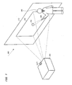
Fig. 1 is a schematic illustrative view of a
presentation system that uses a laser pointer in accordance
with an example of this embodiment of the present
invention;
Fig. 2 is a functional block diagram of the image
processing section within a prior-art projector;
Fig. 3 is a functional block diagram of the image
processing section within a projector in accordance with an
example of this embodiment of the present invention; and
Fig. 4 shows an example of the method of deriving the
chromaticity correction coefficients δ when Y = Y1.
DETAILED DESCRIPTION
The description below relates to a case in which the
present invention is applied to an image display system
which uses a liquid-crystal projector and which can adapt
to the environment, by way of example, with reference to
the accompanying figures.
Description of Overall System
A schematic illustrative view shown in Fig. 1 is of a
presentation system that makes use of a laser pointer 50,
in accordance with an example of this embodiment of the
present invention.
A projector 20 that is provided substantially facing
a screen 10 projects an image for a predetermined
presentation. A presenter 30 gives a presentation to an
audience, while using a light spot 70 projected from the
laser pointer 50 to point at a desired position of an image
in an image display region 12, which is a image-displayed
area on the screen.
During such a presentation, the way in which images
on the image display region 12 are seen will vary greatly,
depending on factors such as the type of the screen 10 and
ambient light 80. When the same white is displayed, for
example, it could seem to be white with a yellow cast or
white with a blue cast, depending on the type of the screen
10. Even when the same white is displayed, it could seem to
be a bright white or a dull white if the ambient light 80
differs.
Recently, the projector 20 has become smaller and
easy to transport. For that reason, it has become possible
to perform presentations at a client's location, by way of
example, but it is difficult to adjust colors to match the
environment at the client's location and the manual
adjustment of colors at the client's location takes too
much time.
A functional block diagram of the image processing
section within a prior-art projector is shown in Fig. 2.
This prior-art projector inputs an R1 signal, a G1
signal, and a B1 signal (which for RGB signals in analog
format, sent from a PC or the like) to an A/D conversion
section 110, and uses a projector image processing section
100 to perform color modification on an R2 signal, a G2
signal, and a B2 signal which have been converted into
digital form by the A/D conversion section 110.
A D/A conversion section 180 converts an R3 signal, a
G3 signal, and a B3 signal, which have been subjected to
the color modification of the projector image processing
section 100, into analog form and outputs them as an R4
signal, a G4 signal, and a B4 signal. A light valve (L/V)
drive section 190 drives liquid-crystal light bulbs to
display an image, based on the R4 signal G4 signal, and B4
signal.
The projector image processing section 100, which is
controlled by a CPU 200, comprises a projector color
conversion section 120 and a profile management section 130.
The projector color conversion section 120 converts
the RGB digital signals (the R2 signal, G2 signal, and B2
signal) into RGB digital signals for projector output (the
R3 signal, G3 signal, and B3 signal), based on a projector
input-output profile that is managed by the profile
management section 130. Note that "profile" in this case
refers to characteristic data.
In this manner, the prior-art projector can only
perform color modification based on an input-output profile
that indicates input-output characteristics that are
specific to that particular projector, so no consideration
is paid to the visual environment in which the image is
projected and displayed.
However, it is difficult to make the way in which
colors are seen uniform in this manner, without taking the
visual environment into account. The way in which colors
are seen is determined by three factors: light, the
reflection or transmission of light by objects, and vision.
This embodiment of the present invention implements
an image display system that can reproduce an image with
the same visual appearance, by determining the visual
environment of light and the reflection or transmission of
light by objects, irrespective of the environment in which
it is applied.
More specifically, the device is provided with a
colored-light sensor 417 that functions as visual
environment detection means for determining the visual
environment, as shown in Fig. 1, and environmental
information from the colored-light sensor 417 is input to
the projector 20. To be more specific, the colored-light
sensor 417 measures colored-light information (more
specifically, information indicating xyY colors and
brightness) of the image display region 12 within the
screen 10.
The projector 20 is provided with color control
processing means that stores and manages brightness
correction information, for correcting the brightness of
the image based on this environmental information, and
color correction information, for correcting the colors of
the image based on this environmental information, and
correction means that corrects the image information for
displaying the image, based on the environmental
information, the brightness correction information, and the
color correction information.
The description now turns to the function blocks of
the image processing section of the projector 20, which
comprises this color control processing means and this
correction means.
A functional block diagram of the image processing
section within the projector 20 in accordance with an
example of this embodiment of the invention is shown in Fig.
3.
The image processing section comprises an input
signal processing section 401 to which RGB signals are
input, a color control processing section 420, a
calibration section 430 that functions as correction means,
an output signal processing section 405, and an L/V drive
section 406.
The input signal processing section 401 comprises an
A/D conversion section 440 that converts the R1, G1, and B1
analog image signals into the R2, G2, and B2 digital image
signals.
The color control processing section 420 comprises a
one-dimensional look-up table (1D-LUT) 402 for input signal
processing, a three-dimensional look-up table (3D-LUT)
storage section 403 that is used in correcting the color
information, and a 1D-LUT storage section 404 that is used
in correcting the brightness information.
Note that a gamma table and color balance table (or
just one of them) are stored as part of the brightness
correction information in the 1D-LUT storage sections 402
and 404. Similarly, a color gamut correction table and a
color temperature correction table (or just one of them)
are stored as part of the color correction information in
the 3D-LUT storage section 403.
In the art, color control is done with a 1D-LUT and
brightness correction is done by determining what potential
is used when sampling the input signal.
During the correction of the brightness of colors to
be reproduced, it is necessary to boost the output of
lower-range grayscale. In this case, brightness correction
is performed by a 1D-LUT that can manipulate a grayscale
characteristic.
As previously described, color correction is done
with a 3D-LUT, to ensure appropriate color compression or
color expansion for each color when it comes to matching
other reproducible color gamuts by color control.
In this manner, brightness and color can be corrected
separately, based on environmental information relating to
brightness and environmental information relating to color,
making it possible to perform each type of correction more
precisely.
The description now turns to color correction, which
will be followed by a description of brightness correction.
Color Correction
The calibration section 430 comprises a calibration
image presentation section 407 which inputs image signals
for calibration (correction) to the input signal processing
section 401, a color conversion section 408 which converts
colors for conversion (stored in the 3D-LUT storage section
403) from the RGB color system into the XYZ color system,
and an environmental correction processing section 410
which performs color and brightness correction, based on
environmental information that is input from the colored-light
sensor 417.
Note that the RGB system results in device-dependent
colors that vary with the input-output device, such as a
projector, but the XYZ system results in non-device-dependent
colors.
The calibration section 430 comprises a Gamut
information management section 412 and a chromaticity
correction coefficient processing section 411.
The Gamut information management section 412 manages
the color gamut information of the image to be depicted.
The color gamut information is supplied to the chromaticity
correction coefficient processing section 411 and used in
the derivation of chromaticity correction coefficients δ.
The chromaticity correction coefficient processing
section 411 draws a plurality of similarly-shaped triangles
of the reproducible color gamut, based on the RGB colors
from the Gamut information management section 412. The
chromaticity correction coefficient processing section 411
derives chromaticity correction coefficients (such as δ (x1,y1
, Y1)) that are based on color information (such as x1,y1
, Y1) from the environmental correction processing
section 410.
An example of the method of deriving the chromaticity
correction coefficients δ when Y = Y1 is shown in Fig. 4.
When RGBW (where W means white (or gray)) color
triangles are drawn on an xy chromaticity chart, the result
is as shown in Fig. 4, by way of example.
The chromaticity correction coefficient processing
section 411 assumes that the chromaticity correction
coefficient for the color of the range between the
outermost triangle and the one within it (the center
triangle) is δ = m ξ. Similarly, it assumes that the
chromaticity correction coefficient for the color of the
range between the center triangle and the innermost
triangular is δ = n ξ. In this case, m and n are
coefficients. It also assumes that the chromaticity
correction coefficient for the color of the range within
the innermost triangle is δ = ξ.
Thus the chromaticity correction coefficient
processing section 411 obtains chromaticity correction
coefficients ( δ (x1, y1, Y1)) relating to the color
information (x1, y1, Y1) that is input from the input
signal processing section 401, and outputs those
chromaticity correction coefficients to the environmental
correction processing section 410.
It is therefore possible to reproduce colors suitably
(perform color correction), by modifying the chromaticity
correction coefficients in accordance with the input colors.
The environmental correction processing section 410
also inputs environmental information from the colored-light
sensor 417.
The colored-light sensor 417 functions as a visual
environment detection means that determines the visual
environment. The colored-light sensor 417 could be one or a
combination of several different devices, such as a
luminance sensor that measures the luminance value of the
image-displayed area, a colored-light sensor that measures
the RGB values or XYZ values of the image-displayed area,
or a chromaticity sensor that measures the chromaticity
values of the image-displayed area.
In other words, the environmental correction
processing section 410 could also input a plurality of
items of environmental information from the colored-light
sensor 417. In such a case, the environmental correction
processing section 410 would have to perform weighting in
accordance with the input environmental information (such
as weighting of luminance, color temperature, and color
information).
To reduce the processing load due to such weighting,
the environmental correction processing section 410 is
provided with an environmental information collecting
section 450 that collects a plurality of items of
environmental information all together.
The environmental information collecting section 450
performs predetermined processing on a plurality of items
of environmental information to obtain a single of
environmental information.
Since it is possible to express color temperature and
correlated color temperature in chromaticity coordinates (x,
y), these can be collected as xyX.
The following equations can be applied as a more
specific example of the collection for a single item of
environmental information, by way of example.
Δx = a1x1 + a2x2 + ··· + apxp
Δy = a1y1 + a2y2 + ··· + aqyq
ΔY = b1Y1 + b2Y2 + ··· + brYr
In this case, a and b are the previously described
weighting coefficients. In this manner, weighting can be
done in a collected manner to derive coordinated correction
requests Δx, Δy, and ΔY that are necessary for correcting
for various environmental influences. The subsequent
circuitry can perform the necessary corrections in a simple
manner, by using Δx, Δy, and ΔY. Note that Δx, Δy, and
ΔY in this case are derived from a comparison with
environmental information for an ideal state.
The environmental correction processing section 410
performs color correction by using the color information
(Δx, Δy) from within the collected environmental
information.
More specifically, the environmental correction
processing section 410 performs the processing described
below upon color information (such as X1, Y1, and Z1) from
a 3D-LUT storage section 409, in order to overwrite
corresponding colors of the 3D-LUT storage section 403.
First of all, the environmental correction processing
section 410 performs the following calculations to obtain
chromaticity coordinates (x1, y1):
x1 = X1 / (X1 + Y1 + Z1)
y1 = Y1 / (X1 + Y1 + Z1)
The environmental correction processing section 410
then outputs color information (x1, y1, Y1) to the
chromaticity correction coefficient processing section 411
and inputs chromaticity correction information (δ (x1, y1,
Y1)) from the chromaticity correction coefficient
processing section 411.
The environmental correction processing section 410
obtains chromaticity (x2, y2) based on environmental
information (Δ x, Δ y), chromatic correction information
( δ ) that has been collected by the environmental
information collecting section 450, and chromaticity (x1,y1
). More specifically, following equations could be used
for the conversion, by way of example:
x2 = Kx(x1, Δx, δ)
y2 = Ky(y1, Δy, δ)
z2 = 1 - x2 - y2
X'1 = x2(X1 + Y1 + Z1)
Y'1 = y2(X1 + Y1 + Z1)
Z'1 = z2(X1 + Y1 + Z1)
The environmental correction processing section 410
outputs the thus-obtained tri-stimulus values (X'1, Y'1,
Z'1) to a post-correction 3D-LUT storage section 414.
The color conversion section 408 converts the (X'1,
Y'1, Z'1) values in the post-correction 3D-LUT storage
section 414 into (R'1, G'1, B'1) values, then outputs the
converted (R'1, G'1, B'1) values to the 3D-LUT storage
section 403.
In the 3D-LUT storage section 403, the colors at the
mapping destination of the 3D-LUT are overwritten by using
(R'1, G'1, and B'1).
In this manner, it is possible to reproduce colors to
suit the visual environment, by overwriting the colors of
the 3D-LUT in the 3D-LUT storage section 403, based on the
visual environment.
Brightness Correction
The description now turns to brightness correction.
This brightness correction is mainly done by
correcting the γ values in each 1D-LUT stored in the 1D-LUT
storage section 402 and the 1D-LUT storage section 404, by
γ correction section 413.
The γ correction parameter ΔY that was obtained by
the environmental correction processing section 410, using
the above described method, is input by the environmental
correction processing section 410 to the γ correction
section 413.
The γ correction section 413 performs γ correction
processing based on ΔY from the environmental correction
processing section 410, to convert γ 1 of the 1D-LUT
storage section 402 into γ1' and γ2 of the 1D-LUT storage
section 404 into γ2'.
In this manner, it is possible to reproduce
brightness to suit the visual environment, by overwriting
the 1D-LUTs of the 1D-LUT storage sections 402 and 404,
based on the visual environment.
The output signal processing section 405 inputs image
signals (R5, G5, and B5) that have been adjusted by using
the look-up tables (LUTs) that have been subjected to
brightness correction by the 1D-LUT storage sections 402
and 404 and color correction by the 3D-LUT storage section
403.
The output signal processing section 405 uses a D/A
conversion section 441 to convert the digital image signals
(R5, G5, and B5) into analog image signals (R6, G6, and B6),
then outputs the converted analog image signals to the L/V
drive section 406.
The L/V drive section 406 uses those analog image
signals to drive liquid-crystal light bulbs to regulate the
image projected from the projector 20.
In this above described manner, the way in which the
image is seen in the image display region 12 of the screen
10 can be adjusted as appropriate by adjusting the image
projected by the projector 20.
This embodiment of the present invention therefore
ensures that the projector 20 takes the visual environment
into consideration when projecting and displaying an image.
This makes it possible for the projector 20 to absorb
differences between display environments and thus display
the same image regardless of the environment in which it is
used. This embodiment of the present invention therefore
enables the reproduction of substantially the same colors
within a short time, in a plurality of different locations.
The projector 20 can also boost the output of lower-range
grayscale and correct the brightness of the
reproduced colors by using a 1D-LUT that enables
manipulation of the grayscale characteristic during the
brightness correction.
The projector 20 can also apply color compression and
color expansion independently for each color, by using a
3D-LUT for the color correction.
In this manner, the projector 20 can apply brightness
correction and color correction separately, based on
environmental information relating to brightness and
environmental information relating to color, thus enabling
it to apply both types of correction more precisely.
Description of Hardware
Note that the various means described below could be
applied as hardware to be used in the previously described
components.
For example, the input signal processing section 401
could be implemented by using an A/D converter or the like,
the color control processing section 420 could be
implemented by using RAM or a CPU or the like, the output
signal processing section 405 could be implemented by using
a D/A converter or the like, the L/V drive section 406
could be implemented by using a liquid-crystal light bulb
driver or the like, and the calibration section 430 could
be implemented by using an image processing circuit or the
like. Note that these components could be implemented by
hardware such as circuitry, or by software such as drivers.
The functions of these components could also be
implemented by the reading of information from an
information storage medium 500. Means such as a CD-ROM,
DVD-ROM, ROM, RAM, or hard disk can be used as the
information storage medium 500, and either a direct method
or an indirect method could be used for reading that
information.
Instead of the information storage medium 500, it is
also possible to implement the above described functions by
downloading a program for implementing those functions from
a host device or the like, through a transfer path. In
other words, a program or the like for implementing the
above described functions could be embodied over carrier
waves.
The present invention has been described above by way
of an ideal embodiment thereof but the application of the
present invention is not limited to that embodiment.
Modifications
The LUTs stored in the previously described 1D-LUT
storage sections 402 and 404 could provide values that are
scattered, such as in a mapping table form, or they could
provide continuous values, such as those derived from
functions.
Note that if values are in a dispersed form, such as
in a mapping table, substantially continuous values
(corresponding colors) can be obtained by interpolation
using a method such as Lagrange interpolation or linear
interpolation.
In the embodiment of the present invention described
above, the colored-light sensor 417 was used as the visual
environment detection means by way of example, but an input
means that inputs at least some part of the environmental
information (such as the presence/absence of external light,
the illumination type, or the screen type) or an image
display means that displays an image for prompting the
input of such details could be used therefor. Both the
colored-light sensor 417 and means for displaying a screentype
input image for acquiring information such as the
screen type could be used together as the visual
environment detection means.
With a screen, in particular, it is easy for people to
distinguish the type of the screen easily, so it is
possible to use the above described image display means to
show choices for selecting the screen type, thus making it
possible to reproduce colors with accurate consideration of
the screen type.
In this case, the visual environment determined by
the visual environment detection means applies to factors
such as ambient light (such as artificial light or natural
light) and the object on which the image is displayed (such
as a display, wall surface, or screen).
In particular, this embodiment of the present
invention makes it possible to apply more appropriate image
correction by obtaining information on a component that is
not much considered in the prior art (i.e., the screen),
thus enabling the reproduction of more uniform image colors.
Note that the screen 10 described above is of a
reflective type, but it could equally well be of a
transparent type. If the screen is of a transparent type, a
sensor that scans the screen directly could be used as the
colored-light sensor.
Similarly, the present invention can also be applied
to presentations done by displaying images by a display
means other than a projection means such as the previously
described projector. Other than a liquid-crystal projector,
a projector using a digital micromirror device (DMD), a
cathode ray tube (CRT), a plasma display panel (PDP), a
field emission display (FED) device, an electroluminescence
(EL) device, or a direct-vision type of liquid
crystal display device could be used as such a display
means. Note that DMD is a trademark registered to Texas
Instruments Inc. of the USA.
It should be obvious that the present invention would
also be effective when displaying images in applications
that are not presentations, such as in meetings, for
medical treatment, in the design or fashion world, in
business activities, and in education, as well as for
general-purpose image displays such as movies, TV, video,
and games.
In some cases, the A/D conversion section 440 is not
necessary when the input signal (R1, G1, B1) is in digital
form, and the D/A conversion section is also not necessary
when the output signal (R6, G6, B6) is digital form. This
can be done as necessary in accordance with the input
devices and output devices that are used.
Note that the functions of the previously described
image processing section of the projector 20 could be
implemented by a simple image display device (such as the
projector 20), or they could be implemented by being
distributed between a plurality of processing devices (such
as processing that is distributed between the projector 20
and a PC).
In above embodiment, information in xyY (or Yxy) form
is used as color information comprising brightness
information, but it could equally well be in another format
such as Lab, Luv, or LCh.
The above described environmental information could
also be values that express color and brightness in a form
such as xyY, but it could also be color and brightness
correction amounts in a form such as ΔxΔyΔY.
In addition, the embodiment described above related
to application to a front-projection type of projector, but
the present invention can equally well be applied to a
rear-projection type of projector.