EP1178599B1 - Open-loop step motor control system - Google Patents
Open-loop step motor control system Download PDFInfo
- Publication number
- EP1178599B1 EP1178599B1 EP01121258A EP01121258A EP1178599B1 EP 1178599 B1 EP1178599 B1 EP 1178599B1 EP 01121258 A EP01121258 A EP 01121258A EP 01121258 A EP01121258 A EP 01121258A EP 1178599 B1 EP1178599 B1 EP 1178599B1
- Authority
- EP
- European Patent Office
- Prior art keywords
- motor
- microsteps
- controller
- phase
- energy
- Prior art date
- Legal status (The legal status is an assumption and is not a legal conclusion. Google has not performed a legal analysis and makes no representation as to the accuracy of the status listed.)
- Expired - Lifetime
Links
- 238000004804 winding Methods 0.000 claims abstract description 63
- 230000001965 increasing effect Effects 0.000 claims abstract description 17
- 230000003247 decreasing effect Effects 0.000 claims abstract description 13
- 238000000034 method Methods 0.000 claims description 18
- 238000006073 displacement reaction Methods 0.000 claims description 16
- 230000008859 change Effects 0.000 claims description 12
- 230000000630 rising effect Effects 0.000 claims description 10
- 239000012530 fluid Substances 0.000 claims description 7
- 230000007246 mechanism Effects 0.000 claims description 7
- 230000001133 acceleration Effects 0.000 description 34
- 239000013598 vector Substances 0.000 description 16
- 230000005534 acoustic noise Effects 0.000 description 8
- 238000010586 diagram Methods 0.000 description 6
- 230000000694 effects Effects 0.000 description 5
- 238000001802 infusion Methods 0.000 description 5
- 238000013459 approach Methods 0.000 description 4
- 230000002572 peristaltic effect Effects 0.000 description 4
- 230000008901 benefit Effects 0.000 description 3
- 230000006870 function Effects 0.000 description 3
- 230000004048 modification Effects 0.000 description 3
- 238000012986 modification Methods 0.000 description 3
- 238000012886 linear function Methods 0.000 description 2
- 230000009467 reduction Effects 0.000 description 2
- 238000012546 transfer Methods 0.000 description 2
- 230000006978 adaptation Effects 0.000 description 1
- 238000004364 calculation method Methods 0.000 description 1
- 230000007423 decrease Effects 0.000 description 1
- 238000010438 heat treatment Methods 0.000 description 1
- 230000001939 inductive effect Effects 0.000 description 1
- 239000003978 infusion fluid Substances 0.000 description 1
- 238000004519 manufacturing process Methods 0.000 description 1
- 230000010355 oscillation Effects 0.000 description 1
- 238000005086 pumping Methods 0.000 description 1
- 230000004044 response Effects 0.000 description 1
- 239000007787 solid Substances 0.000 description 1
- 230000003068 static effect Effects 0.000 description 1
- 230000007704 transition Effects 0.000 description 1
Images


Classifications
-
- H—ELECTRICITY
- H02—GENERATION; CONVERSION OR DISTRIBUTION OF ELECTRIC POWER
- H02P—CONTROL OR REGULATION OF ELECTRIC MOTORS, ELECTRIC GENERATORS OR DYNAMO-ELECTRIC CONVERTERS; CONTROLLING TRANSFORMERS, REACTORS OR CHOKE COILS
- H02P8/00—Arrangements for controlling dynamo-electric motors rotating step by step
- H02P8/22—Control of step size; Intermediate stepping, e.g. microstepping
-
- H—ELECTRICITY
- H02—GENERATION; CONVERSION OR DISTRIBUTION OF ELECTRIC POWER
- H02P—CONTROL OR REGULATION OF ELECTRIC MOTORS, ELECTRIC GENERATORS OR DYNAMO-ELECTRIC CONVERTERS; CONTROLLING TRANSFORMERS, REACTORS OR CHOKE COILS
- H02P8/00—Arrangements for controlling dynamo-electric motors rotating step by step
- H02P8/04—Arrangements for starting
-
- H—ELECTRICITY
- H02—GENERATION; CONVERSION OR DISTRIBUTION OF ELECTRIC POWER
- H02P—CONTROL OR REGULATION OF ELECTRIC MOTORS, ELECTRIC GENERATORS OR DYNAMO-ELECTRIC CONVERTERS; CONTROLLING TRANSFORMERS, REACTORS OR CHOKE COILS
- H02P8/00—Arrangements for controlling dynamo-electric motors rotating step by step
- H02P8/24—Arrangements for stopping
-
- H—ELECTRICITY
- H02—GENERATION; CONVERSION OR DISTRIBUTION OF ELECTRIC POWER
- H02P—CONTROL OR REGULATION OF ELECTRIC MOTORS, ELECTRIC GENERATORS OR DYNAMO-ELECTRIC CONVERTERS; CONTROLLING TRANSFORMERS, REACTORS OR CHOKE COILS
- H02P8/00—Arrangements for controlling dynamo-electric motors rotating step by step
- H02P8/32—Reducing overshoot or oscillation, e.g. damping
Definitions
- the invention relates generally to motor control and more particularly, to open-loop step motor control systems that reduce acoustic noise while maintaining sufficient torque.
- a step motor applies torque to its load in a series of discrete steps and consequently may act as a sound transducer, generating an audible tone with a fundamental frequency equal to its step rate. If the motor is to be operable over a wide range of step rates, one or more of these rates will probably excite resonant frequencies of the motor's mechanical load, or of the motor itself, resulting in the production of objectionable amounts of acoustic noise and in less efficient operation. In the medical equipment field, it is usually desirable to lower the noise level of the equipment for the benefit of the patient and others.
- infusion pumps containing step motors are generally located next to a patient and may operate for hours. It can be disturbing to a patient when the pump generates a large amount of noise.
- certain medical equipment including many infusion pumps, must be powered by a portable power supply having a limited reservoir of power, such as batteries, and therefore the equipment must be designed to consume as little power as possible. In this way, the equipment can support the patient for as long as possible before a battery change or recharge is required.
- lowered levels of noise and lowered levels of power consumption are desirable characteristics in infusion pumps and other medical equipment.
- a source of acoustic noise in a step motor is the wave shape of the motor drive.
- the simplest means of driving a step motor is the "full step” mode in which a two-phase motor is driven by a current or voltage square wave of constant magnitude.
- each step corresponds to one of 2 N possible motor winding current polarity states where N is the number of motor windings (or phases).
- This type of drive generates acoustic noise with high harmonic content due to the high angular acceleration resulting from the high rate of change of torque that occurs at the leading edge of each step.
- the noise component can be reduced if the magnitude of the torque pulses is decreased by reducing the magnitude of the motor drive pulse.
- the motor's rated torque should be high enough to handle all of these circumstances but in any case, its rated torque plus its torque reserve must be high enough or motor pullout may occur.
- a mechanism has a rated torque and a torque reserve.
- the reserve torque is set at seventy percent of the rated "no stall" torque. It has been found that motor noise can be significantly reduced by the technique known as “microstepping.” "Microstepping” is a means of driving a motor through a step with a series of current magnitude states that generate smaller angular displacements of the motor magnetic field vector position. The sum of these displacements equals that of one step.
- microstepping In the microstep technique, motor winding currents, that define the state sequence, must be maintained throughout the sequence, resulting in relatively high power consumption.
- Other lower power consumption step modes are available, such as "one phase on” mode where winding currents are turned off after the initial acceleration to conserve power. However, these modes are noisier than the microstepping mode.
- Microstepping is also not desirable where controller bandwidth is limited. As the number of microsteps increases, the controller bandwidth requirement increases requiring greater hardware capability to support a faster clock speed. This greater ability results in increased expense and complexity.
- the type of motor drive circuit can also have a direct effect on expense.
- closed-loop drive circuits typically require sensors to provide the necessary feedback for control.
- the cost of sensor as well as the additional processor bandwidth required to use the sensor inputs to control the drive circuit can result in a substantial increase in cost.
- An open-loop system is preferable in this regard.
- US 4,683,408 discloses a stepping motor control apparatus which calculates a motor-coil exciting current corresponding to a holding position, the calculation being based on a predetermined wave form pattern.
- the stepping motor is driven towards the final holding position through a microstep transfer distance which is shorter than a regular step transfer interval.
- the stepping motor arrangement disclosed in this document still suffers from disadvantageous acoustic output.
- US 4,418,907 discloses a method and arrangement for controlling a "digital" motor which is configured to allow operation of the motor in a microstepping mode at low velocity, but to allow operation in a non-microstepping mode at a higher motor velocity in order to take advantage of the higher torque available at higher velocities.
- WO91/10946 discloses a motor drive arrangement for controlling and driving a peristaltic pump motor, in which the length of a drive signal is determined by the frequency of a first series of pulses generated by a first circuit at a given frequency.
- a second circuit is also provided which generates a second series of pulses having a frequency which is higher than the frequency of the first series of pulses.
- a third circuit is provided which generates the third series of pulses having a frequency falling between the frequency of the first and second series of pulses.
- the drive signal is divided into two sections, namely an initial pulse stage determined by the frequency of the third series of pulses, and a modulated pulse stage being a series of pulses determined by the frequency of the second series of pulses.
- the present invention is directed to a control system for controlling the movement of a motor, the system comprising an energy source and a controller for controlling the application of energy to the motor from the energy source to control movement of the motor, wherein the controller applies energy to the motor in a non-linear increasing manner to begin movement of the motor.
- a control system for controlling the movement of a step motor comprising:
- the controller maintains a constant microstep period.
- the controller applies energy from the energy source to accelerate the motor through a third motor step, wherein the third motor step includes a third plurality of microsteps, wherein the second plurality of microsteps is greater than the third plurality of microsteps.
- the controller applies energy from the energy source to the motor in a "one phase on” drive mode modified to microstep between the "one phase on” positions during movement of the motor, wherein the controller controls the motor by varying the number of microsteps per motor step while maintaining a constant microstep period; wherein the controller controls the motor to accelerate by decreasing the number of microsteps per motor step while maintaining a constant microstep period.
- controller removes energy from the motor in a "one phase on” drive modified to microstep between the “one phase on” positions during movement of the motor ending in a “one phase on” position for the last step of the motor before power is completely removed, and wherein the controller controls the motor to decelerate by increasing the number of microsteps per motor step while maintaining a constant microstep period.
- the controller applies energy to the motor in a full step drive mode after the motor has achieved a preselected speed.
- the controller applies energy from the energy source to the motor such that the motor moves with one microstep per motor step during which one of at least two phases of the step motor changes polarity while the other phase remains at a constant value, and a step rate being selected such that the polarity change is performed in one motor step period whereby smooth motor field displacement is achieved.
- the step motor drives a pump mechanism for delivering medical fluid to a patient.
- a method of controlling movement of a step motor that moves in a series of motor steps comprising:
- both steps of controlling the step motor to move include maintaining a constant period for the microsteps.
- the step motor has at least two phases and a permanent magnet that defines a detent position at rest, the method further characterised by:
- the method includes :
- the method involves driving a pump mechanism with the step motor for delivering medical fluid to a patient.
- the step motor 10 includes a rotor 12 having a permanent magnet and being rotational about a pivot point 13, and two pairs of stator windings 14 and 16. Each stator winding represents a phase of the step motor.
- the winding 14 will represent phase A
- the winding 16 will represent phase B.
- the rotor 12 moves in steps in accordance with the magnitude and polarity of the current applied to the respective windings 14 and 16.
- the "microstep” drive mode utilizes this effect and subdivides the basic motor step by proportioning the current applied to the two windings. For example, by alternately energizing one winding and then two, the rotor moves through a smaller angular displacement and the number of steps per revolution is doubled. Higher resolution, better smoothness but some loss of torque result.
- This mode is commonly known as "half-step” drive mode.
- the two windings or phases are kept energized, and the current is alternately reversed in each winding on alternate steps.
- FIG. 2 shows a processor 20 that provides signals for driving the step motor 10.
- the processor 20 or other suitable digital system accesses data from look-up tables stored in a memory 22 so as to provide signals defining the waveform for driving the step motor 10 in a particular mode.
- the tables in memory 22 provide values for the polarities and magnitudes of the currents to be applied to the windings of the motor 10.
- the processor 20 supplies the polarity and magnitude signals to the drivers 26 for providing the proper currents to the windings of the step motor 10.
- the values are put through a D/A converter 28 to convert them to analog signals before being input to the drivers 26. As shown in FIG.
- the drivers 26 for the windings 14 and 16 of the two-phase step motor 10 comprise a pair of H bridges 30 controlled by the processor.
- the magnitudes of the H bridge current outputs are controlled by choppers 32.
- the choppers 32 act to turn the motor drive on or off as required to minimize the difference between the sense and the magnitude signals at the comparator inputs 33.
- the magnitude signals are generated via the D/A converters 28 (FIG. 2).
- the processor 20 switches between the separate tables stored in the memory 22 that contain the specific data for providing the appropriate waveform to drive the step motor.
- the memory 22 in one embodiment contained multiple look up tables, each of which was available to the processor for use during operation of the motor through each group of steps.
- the processor is thus able to change motor drive waveforms "on the fly” and automatically does so as described herein.
- the look up table index is changed during motor rotation so that the processor always has the proper waveforms available for controlling the motor. For example, a look up table was stored for the acceleration waveforms and another was stored for the full step waveform.
- FIG. 3 also shows drive current by arrows having dashed stems and decay currents by arrows having solid stems 31 for the phase A winding
- the choppers 32 turn the transistors A1 and A2 on depending on the result of the comparison of the magnitude signal to the sense signal by the comparator 33.
- step motors 10 used with medical infusion pumps such as the linear peristaltic pump 34 shown in FIG.
- a full step drive mode shown in FIG. 4 at a constant step rate may not be the most efficient mode for operating the motor 10 to reduce noise and power consumption.
- the resulting step period can have an excessive duration in which the majority of motion of the motor occurs near the beginning of the period with power wasted as heat in the resistance of the windings 14 and 16 for the remainder of the period and objectionable noise resulting.
- FIG. 5 an embodiment is shown in which energy is applied to the motor in a non-linear manner to begin motor movement.
- the winding current 42 is applied in an exponential manner to cause the motor to attain its maximum torque at a rate faster than if a linear increase in winding current 44 were used.
- FIG. 5 presents a graph of motor movement as a result of the exponential application of power shown in FIG. 5. The motor more quickly attains the maximum angular velocity 43 through exponential acceleration 45 than through a linear acceleration 47.
- each time frame 48 and 50 of phase currents A 51 and B 53 for a step motor drive are shown.
- the motor is moved through a predetermined group of steps 52, 54, and 56 and is then stopped for the remainder of the time frame 58. Therefore, each time frame includes periods of acceleration 52, maximum step rate 54, deceleration 56, and power off or stop 58 (although numerals are only shown on one frame).
- FIG. 8 shows two winding current waveforms 51 and 53 of the group of steps in a single time frame of FIG. 7 in greater detail. FIG. 8 will be considered with the vector diagrams in FIG. 9 in the following discussion.
- the 9 contains graphs showing acceleration-deceleration and constant speed vector sequences for the two-phase step motor 10 driven by the waveform shown in FIG. 8.
- the graphs illustrate the three portions of the waveform, and their corresponding motor steps and microsteps.
- the vectors indicate the direction and magnitude of the motor magnetic field acting on the rotor 12 at each microstep.
- the acceleration portion illustrates the rapidly increasing step rate (i.e., decreasing microsteps for successive steps) as the rotor increases speed by use of a modified "one phase on" mode.
- the high speed portion maintained by the modified full-wave waveform maintains the motor's constant speed with accurate positioning.
- the deceleration portion illustrates the rapidly decreasing step rate as the motor decreases speed again with a modified "one phase on” mode.
- microstep no
- the rotor is near its detent position before current to the motor windings is discontinued.
- the rotor stops in a "one phase on” position before the winding is turned off.
- the rotor is then held in position by the detent torque produced by the permanent magnet of the rotor until the next group of steps is applied to the motor. This results in accurate positioning of the motor without use of current to hold the position.
- the motor is driven with a modified "one phase on" waveform. This corresponds to steps 1-4 and 16-18, wherein each step begins and ends with the motor in a detent position where the one energized winding or phase can be turned on or off without any resulting motor torque.
- a modified "one phase on" drive mode is used to result in smoother acceleration by the motor.
- the magnetic field is not precisely in the detent position but is retarded somewhat at the end of acceleration in motor steps 2 and 3 to prepare the rotor for the transition to high speed drive.
- the field is similarly retarded slightly at the end of each deceleration step to prepare the rotor to coast to a stop precisely at a detent position at the moment the winding current is removed.
- the amount that the second winding is energized to accomplish this modification depends on the physical parameters of the motor.
- the rotor moment of inertia, the frictional loads (static, gravitational, and viscous), the torque output of the motor, the strength of the detent field and the resistance and inductance of the motor windings all may affect the noise of the motor and can be considered in selecting the modification of the "one phase on” waveform.
- the "one phase on” drive modes are modified to microstep between "one phase on” positions of the rotor during movement of the motor.
- the torque may be increased and a smooth field vector displacement sequence provided by temporarily energizing more than one winding during each step.
- Microsteps are used in the modified "one phase on” waveform to lessen the angular displacement and noise and to provide smoother acceleration for the motor.
- a preferred microstep sequence generates an exponentially rising current magnitude throughout the initial acceleration step as shown in FIG. 5.
- the motor is preferably accelerated at the beginning of the time frame at an exponentially rising step rate until the maximum step rate for the motor is attained in a minimum time.
- An exponentially rising step rate allows the step rate to move past the resonance frequencies of the motor more quickly, thereby reducing acoustic noise, after starting the motor from a stationary position with a low initial angular acceleration.
- Noise is reduced by starting the motor from a stationary position with a lower rate of change of torque than would occur with a linear increase in the motor current vector magnitude.
- the final current vector magnitude of a motor step must be sufficient to generate the required "torque reserve" that ensures motor startup with a worst-case mechanical load.
- a rising exponential current profile permits this final value to be attained in a given period, i.e., a step of the motor, with a lower initial rate of change of current and torque.
- the low initial torque reduces power consumption as well as noise. Because torque is a linear function of winding current for operation below saturation, only a low initial winding current is required, that reduces power consumption.
- the current levels in the initial acceleration steps have the most significant effect on power consumption, as these steps are of the longest duration of the group of steps. All of the steps contain microsteps of constant period, and the initial acceleration steps contain the greatest number of microsteps. Use of an exponentially rising acceleration causes the motor to reach its desired maximum speed quickly.
- the acceleration waveform tables stored in the memory 22 can be programmed to increase the winding current as the acceleration progresses in order to supply the increasing torque level required to sustain a nonlinearly rising rate of acceleration.
- the tables stored in the memory contain the values for the microsteps for the step sequences of the waveform for driving the step motor. Furthermore, the controller bandwidth requirement can be minimized by using microsteps having a constant period.
- the motor step rate on succeeding steps during acceleration can be increased by decreasing the number of microsteps per motor step and maintaining a constant microstep period, rather than by decreasing the microstep period and maintaining a constant number of microsteps per step.
- the microstep period is the shortest interval that must be resolved because the microstep determines the required bandwidth of the controller. Normally, acceleration is effected by decreasing this period to achieve a higher rate of microsteps per unit time. Increasing the microstep rate, however, requires an increased controller bandwidth. Keeping the microstep period constant during acceleration keeps the controller bandwidth requirement constant and equal to that for the lowest initial step rate. Since there is one microstep per motor step at the maximum rate, the motor step period at the maximum rate equals the microstep period at the lowest initial rate as shown in FIG.
- a modified full step waveform for the maximum constant rate portion of the group of steps is used for driving the two-phase step motor 10.
- a different waveform may be desirable for step motors having more than two phases. As shown in FIG. 8, for each step of the modified full step waveform 51 and 53, one winding current changes polarity smoothly while the other remains approximately constant.
- V compliance of the controller and the motor inductance, L are constant, the current in the winding undergoing polarity reversal changes approximately as a linear function of time until reaching its final value at the end of the step period.
- Some nonlinearity may be introduced by the resistance of the motor winding.
- the actual field vector displacement is a smooth analog function determined by the inductive decay of the motor windings as shown in FIGS. 10, 11A, and 11B.
- the other winding is held at a constant current 66 equal to or less than the final value of the decay.
- the constant current level 66 is selected to minimize power consumption while providing the required minimum high speed torque for the specified load.
- the motor is driven at its maximum speed, which is chosen to be well above its resonance, the acoustic noise normally associated with full step drive is reduced. Acoustic noise, and power consumption, can be reduced further by optimizing the constant current level as described above to a value that minimizes power consumption while providing the required minimum high speed torque for the specified load. This results in the "modified" full step drive mode. Since one component of the current vector is changing smoothly from initial to final value during each high speed step, the resulting field vector displacement (FIG. 11B) is smooth and less noise is produced.
- each step of the full step waveform 51 and 53 has a period that preferably equals the period of a microstep.
- FIG. 11A shows more detail of part of a waveform of FIG. 10 with arbitrary time increments along the horizontal axis.
- the phase A current 60 can be seen smoothly transitioning polarity within one motor step (eight arbitrary time increments) with resulting lowered noise levels.
- These arbitrary time units are used once again in FIG. 11B to show the field vector displacement within the one motor step. Smooth vector rotation occurs without discrete steps that lead to higher noise levels. Rather than allowing the current to reach the final decay value shown in FIG. 10, the current decay is limited to the constant current level 66 so that it takes one motor step for the polarity reversal.
- the motor is again driven with a "one phase on” waveform modified for microsteps between each "one phase on” position which begins and ends with the motor in a detent position, where the one energized winding or phase at the final step of the group can be turned on or off without any resulting motor torque.
- Microstep drive modes are interspaced with the "one phase on” drive positions to increase torque and to provide a smooth field vector displacement sequence. No power is required to hold the motor in the final stationary detent position for the group of steps.
- the permanent magnet in the rotor 12 holds the step motor 10 in the detent position. Thus power can be turned off between groups of steps to reduce the average power consumption of the step motor 10 over a time frame.
- the processor 20 switches table indices to progress through the separate tables that contain the acceleration, high speed, and deceleration waveforms.
- the number of steps in the time frame, the total time of the time frame, and the length of the unpowered interval are controlled by the processor 20 to precisely determine the average step rate of the motor.
- Certain medical devices, such as fluid pumps, may employ rotation at a selected average rate by grouping steps to dispense infusates at the proper dosage. For example, see U.S. Patent Application serial no. 08/305,677 filed September 12, 1994 to Butterfield et al. entitled System for Increasing Flow Uniformity.
- the same maximum step rate and acceleration-deceleration profile can be used for any desired average step rate, and optimum efficiency can be achieved at all average step rates by selecting an optimally high step rate.
- the same compliance voltage for the step motor can be used at all average rates because the same maximum step rate for the motor is used. Only the number of steps in the group of steps and the unpowered interval need be changed to adjust the average rate desired for the motor.
- the compliance voltage is the maximum voltage required to maintain a specific value of current over a range of load resistances. The required drive algorithm and hardware are simplified from that required to optimize the efficiency of a motor using a maximum rate step drive because the same constant step rate is used to achieve any desired average rate.
- the same maximum step rate for the waveform, selected for optimum motor efficiency, is used regardless of the desired average step rate.
- a lower and less efficient constant step rate must be used in order to attain the desired average step rate.
- the step motor 10 when driven by the combination of drive modes described above has a lower average power consumption than one driven by a constant rate step drive signal. Low power consumption "one phase on” drive modes are used and no power is consumed during the time separating the step groups.
- the efficiency of the motor is optimized by selecting a high maximum step rate whose period matches the required winding current decay time determined by motor inductance and compliance voltage to achieve the waveform shown in FIGS. 10, 11A, and 11B.
- FIG. 12 is a flow chart illustrating the operation of an open-loop control system in accordance with principles of the invention.
- motor movement is to begin 80, the motor accelerates as a result of the exponential application of current to the windings 82.
- a "one phase on” drive mode modified to microstep between "one step on” positions is used with decreasing numbers of microsteps during acceleration 84.
- a modified full step drive is used 88.
- a "one phase on” mode modified to microstep between the "one phase on” positions with increasing numbers of microsteps for deceleration is used 92.
Landscapes
- Engineering & Computer Science (AREA)
- Power Engineering (AREA)
- Control Of Stepping Motors (AREA)
- Control Of Electric Motors In General (AREA)
Abstract
Description
- The invention relates generally to motor control and more particularly, to open-loop step motor control systems that reduce acoustic noise while maintaining sufficient torque.
A step motor applies torque to its load in a series of discrete steps and consequently may act as a sound transducer, generating an audible tone with a fundamental frequency equal to its step rate. If the motor is to be operable over a wide range of step rates, one or more of these rates will probably excite resonant frequencies of the motor's mechanical load, or of the motor itself, resulting in the production of objectionable amounts of acoustic noise and in less efficient operation.
In the medical equipment field, it is usually desirable to lower the noise level of the equipment for the benefit of the patient and others. For example, infusion pumps containing step motors are generally located next to a patient and may operate for hours. It can be disturbing to a patient when the pump generates a large amount of noise. Additionally, certain medical equipment, including many infusion pumps, must be powered by a portable power supply having a limited reservoir of power, such as batteries, and therefore the equipment must be designed to consume as little power as possible. In this way, the equipment can support the patient for as long as possible before a battery change or recharge is required. Thus, lowered levels of noise and lowered levels of power consumption are desirable characteristics in infusion pumps and other medical equipment.
A source of acoustic noise in a step motor is the wave shape of the motor drive. The simplest means of driving a step motor is the "full step" mode in which a two-phase motor is driven by a current or voltage square wave of constant magnitude. In this mode, each step corresponds to one of 2N possible motor winding current polarity states where N is the number of motor windings (or phases). This type of drive generates acoustic noise with high harmonic content due to the high angular acceleration resulting from the high rate of change of torque that occurs at the leading edge of each step. Additionally, where the drive rate is sub-optimum and the rotor reaches its position before the winding currents are switched, a damped oscillation of the rotor about the motor magnetic field position may occur with resulting excess noise and wasted power in providing negative torque to hold the rotor and energy is lost in merely heating the windings due to the resistance encountered.
The noise component can be reduced if the magnitude of the torque pulses is decreased by reducing the magnitude of the motor drive pulse. Such a reduction, however, also reduces the motor's available torque reserve, resulting in an increased risk of motor stall or "pull out" where "pull out" refers to the loss of synchronization because the load on the motor exceeds the power available to the motor to move the load, thus the motor "pulls out" of its movement cycle and loses one or more steps. This condition can result in positioning errors due to the lost steps.
Having an adequate torque reserve is necessary in the case where certain undesirable conditions may occur. In the medical field where a step motor is used to drive a pumping mechanism, such as a peristaltic pump, the head heights of the infusion fluid change, infusates may be particularly viscous, and cold temperatures may require greater power to move the peristaltic mechanism, for example. The motor's rated torque should be high enough to handle all of these circumstances but in any case, its rated torque plus its torque reserve must be high enough or motor pullout may occur. Typically, a mechanism has a rated torque and a torque reserve. In one embodiment, the reserve torque is set at seventy percent of the rated "no stall" torque.
It has been found that motor noise can be significantly reduced by the technique known as "microstepping." "Microstepping" is a means of driving a motor through a step with a series of current magnitude states that generate smaller angular displacements of the motor magnetic field vector position. The sum of these displacements equals that of one step. Because instantaneous torque is approximately a sinusoidal function of the angular displacement of a motor's field vector position from its rotor position, a smaller angular displacement results in a lower instantaneous torque. A lower instantaneous torque generates an angular acceleration at the leading edge of each "microstep" smaller than that which would be generated at the leading edge of each step in "full step" drive mode. The effect is to spread the large acceleration that normally occurs at the beginning of a step over the entire step as a series of small accelerations, thus reducing the level of acoustic noise.
However, "microstepping" is not a satisfactory noise reduction technique if power consumption must be limited, as in battery-powered applications. In the microstep technique, motor winding currents, that define the state sequence, must be maintained throughout the sequence, resulting in relatively high power consumption. Other lower power consumption step modes are available, such as "one phase on" mode where winding currents are turned off after the initial acceleration to conserve power. However, these modes are noisier than the microstepping mode. Microstepping is also not desirable where controller bandwidth is limited. As the number of microsteps increases, the controller bandwidth requirement increases requiring greater hardware capability to support a faster clock speed. This greater ability results in increased expense and complexity. - The type of motor drive circuit can also have a direct effect on expense. For example, closed-loop drive circuits typically require sensors to provide the necessary feedback for control. The cost of sensor as well as the additional processor bandwidth required to use the sensor inputs to control the drive circuit can result in a substantial increase in cost. An open-loop system is preferable in this regard.
- Thus, greater control over power consumption is important in applications where long battery life is desired. Providing excessive power to the step motor windings can cause wasted power and shortened battery life. Power can be lost as heat due to winding resistance. Similarly, moving the motor at its resonance frequency is inefficient and can result in wasted power because relatively little torque is created from the large input power that is provided to the motor. Thus precise motor control is desirable to avoid wasting limited energy.
-
US 4,683,408 discloses a stepping motor control apparatus which calculates a motor-coil exciting current corresponding to a holding position, the calculation being based on a predetermined wave form pattern. The stepping motor is driven towards the final holding position through a microstep transfer distance which is shorter than a regular step transfer interval. However, the stepping motor arrangement disclosed in this document still suffers from disadvantageous acoustic output. -
US 4,418,907 discloses a method and arrangement for controlling a "digital" motor which is configured to allow operation of the motor in a microstepping mode at low velocity, but to allow operation in a non-microstepping mode at a higher motor velocity in order to take advantage of the higher torque available at higher velocities. -
WO91/10946 - Hence those skilled in the art have recognized the need for lowering the acoustic output of medical devices while also lowering the power consumption, but retaining an adequate torque reserve. Additionally, those skilled in the art have also recognized the need for an open-loop control system to reduce hardware and processor costs. The present invention fulfils these needs and others.
- Briefly and in general terms, the present invention is directed to a control system for controlling the movement of a motor, the system comprising an energy source and a controller for controlling the application of energy to the motor from the energy source to control movement of the motor, wherein the controller applies energy to the motor in a non-linear increasing manner to begin movement of the motor.
- According to a first aspect of the present invention, there is provided a control system for controlling the movement of a step motor, comprising:
- an energy source;
- a controller that applies energy from the energy source to accelerate the motor through first and second motor steps, wherein the first motor step includes a first plurality of microsteps, and the second motor step includes a second plurality of microsteps, wherein the first plurality of microsteps is greater than the second plurality of microsteps; characterised in that
- the controller applies energy from the energy source to the motor in a non-linear manner to accelerate the step motor to a preselected motor speed;
- the controller applies energy to maintain the preselected speed for a first predetermined period of time; and
- the controller removes energy from the motor in a non-linear manner to decelerate the step motor to the detent position wherein the motor controller provides no drive signals to the motor after the motor stops in the detent position for a second predetermined period of time.
- Preferably, the controller maintains a constant microstep period.
- Advantageously, the controller applies energy from the energy source to accelerate the motor through a third motor step, wherein the third motor step includes a third plurality of microsteps, wherein the second plurality of microsteps is greater than the third plurality of microsteps.
- Conveniently, the controller applies energy from the energy source to the motor in a "one phase on" drive mode modified to microstep between the "one phase on" positions during movement of the motor, wherein the controller controls the motor by varying the number of microsteps per motor step while maintaining a constant microstep period;
wherein the controller controls the motor to accelerate by decreasing the number of microsteps per motor step while maintaining a constant microstep period. - Preferably, controller removes energy from the motor in a "one phase on" drive modified to microstep between the "one phase on" positions during movement of the motor ending in a "one phase on" position for the last step of the motor before power is completely removed, and
wherein the controller controls the motor to decelerate by increasing the number of microsteps per motor step while maintaining a constant microstep period. - Advantageously, the controller applies energy to the motor in a full step drive mode after the motor has achieved a preselected speed.
- Conveniently, in the full step mode, the controller applies energy from the energy source to the motor such that the motor moves with one microstep per motor step during which one of at least two phases of the step motor changes polarity while the other phase remains at a constant value, and a step rate being selected such that the polarity change is performed in one motor step period whereby smooth motor field displacement is achieved.
- Preferably, the step motor drives a pump mechanism for delivering medical fluid to a patient.
- According to another aspect of the present invention, there is provided a method of controlling movement of a step motor that moves in a series of motor steps, the method comprising:
- controlling the step motor to move through a first accelerating motor step in a first plurality of microsteps;
- controlling the step motor to move through a second accelerating motor step in a second plurality of microsteps, the second motor step being subsequent to the first motor step, wherein the second plurality of microsteps is less than the first plurality of microsteps; the method being characterised by:
- applying energy to the step motor in a rising non-linear manner to accelerate the motor to a preselected motor speed;
- maintaining the preselected speed for a first predetermined period of time; and
- the step motor from the preselected speed to the detent position after the first predetermined period of time, wherein the motor controller provides no drive signals to the motor after the motor stops in the detent position for a second predetermined period of time;
- Preferably, both steps of controlling the step motor to move include maintaining a constant period for the microsteps.
- Advantageously, the step motor has at least two phases and a permanent magnet that defines a detent position at rest, the method further characterised by:
- applying an exponentially increasing winding current in an exponentially rising manner to accelerate the step motor to a preselected motor speed;
- maintaining the preselected speed for a first predetermined period of time; and
- exponentially decreasing the winding current to decelerate the step motor from the preselected speed to the detent position after the first predetermined period of time, wherein the motor stops in the detent position for a second predetermined period of time.
- Conveniently, the method includes :
- decelerating the step motor in a series of decelerating motor steps with a first of said decelerating motor steps divided into a first number of decelerating microsteps, and a second of said decelerating motor steps is divided into a second number of decelerating microsteps;
- Preferably, the method involves driving a pump mechanism with the step motor for delivering medical fluid to a patient.
- Other aspects and advantages of the invention will become apparent from the following detailed description and the accompanying drawings, illustrating by way of example the features of the invention.
-
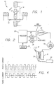
- FIG. 1 is a block diagram illustrating a basic two-phase step motor;
- FIG. 2 is a block diagram of a controller for a step motor in accordance with an aspect of the invention and the application of the controller and step motor to the infusion of medical fluids to a patient;
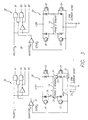
- FIG. 3 is a circuit diagram of the drivers and motor windings shown in FIG. 2 in accordance with an aspect of the invention;
- FIG. 4 presents waveforms of a constant rate two phase step drive for driving a two phase step motor;
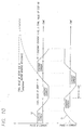
- FIG. 5 is a graph of the non-linear application of energy to a motor to attain a peak winding current, in this case, an exponential application of energy is shown and is compared to a linear application of energy;
- FIG. 6 is a graph of the non-linear acceleration of a motor in response to the exponential application of energy shown in FIG. 5, in this case, an exponential acceleration is shown and is compared to a linear acceleration;
- FIG. 7 includes graphs illustrating the use of multiple drive modes in controlling the application of energy to a step motor;
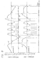
- FIG. 8 illustrates in greater detail, certain waveforms of FIG. 7 in accordance with an aspect of the invention;
- FIG. 9 includes vector diagrams of the drive modes of FIG. 8;
- FIG. 10 illustrates the effect of motor inductance on winding current at high speed resulting in smooth magnetic field displacement;
- FIG. 11A illustrates one of the waveforms of FIG. 10 in further detail and in FIG. 11B, a vector diagram is shown; and
- FIG. 12 is a flow chart of the control of a step motor in accordance with aspects of the invention.
- In the following description, like reference numerals will be used to refer to like or corresponding elements in the different figures of the drawings. The following discussion will be based on the illustrative example of a two-
phase step motor 10 as shown in FIG. 1. Thestep motor 10 includes arotor 12 having a permanent magnet and being rotational about apivot point 13, and two pairs ofstator windings rotor 12 moves in steps in accordance with the magnitude and polarity of the current applied to therespective windings rotor 12, respectively.
There are a number of drive modes for controlling the rotation of the rotor in a step motor. In a "one phase on" drive mode, one winding is fully energized while the other winding is turned off. By changing the current flow from the first winding 14 to the other winding 16, the stator field rotates ninety degrees. Lower power is required in this mode. This results in the rotor turning a step of ninety degrees. As is known in the art, steps of different degrees can be obtained using different rotor and stator configurations. In addition, if the two phase currents are unequal, the rotor will tend to shift to a position towards the stronger pole. The "microstep" drive mode utilizes this effect and subdivides the basic motor step by proportioning the current applied to the two windings. For example, by alternately energizing one winding and then two, the rotor moves through a smaller angular displacement and the number of steps per revolution is doubled. Higher resolution, better smoothness but some loss of torque result. This mode is commonly known as "half-step" drive mode.
For a two-phase step motor driven in "full step" drive mode, the two windings or phases are kept energized, and the current is alternately reversed in each winding on alternate steps. Greater torque can be produced under these conditions because all of the stator poles are influencing the motor. Their individual fields sum to produce a greater magnetic field. However, more power is consumed in this drive mode because both windings are constantly powered.
When there is no current flowing through the windings, the rotor will attempt to minimize the reluctance, or magnetic resistance, of its permanent magnet by aligning itself with the poles of one of the stator windings. The torque holding the motor in this position is referred to as the detent torque. - FIG. 2 shows a
processor 20 that provides signals for driving thestep motor 10. In this embodiment, theprocessor 20 or other suitable digital system accesses data from look-up tables stored in amemory 22 so as to provide signals defining the waveform for driving thestep motor 10 in a particular mode. The tables inmemory 22 provide values for the polarities and magnitudes of the currents to be applied to the windings of themotor 10. Theprocessor 20 supplies the polarity and magnitude signals to thedrivers 26 for providing the proper currents to the windings of thestep motor 10. The values are put through a D/A converter 28 to convert them to analog signals before being input to thedrivers 26.
As shown in FIG. 3, thedrivers 26 for thewindings phase step motor 10 comprise a pair of H bridges 30 controlled by the processor. The magnitudes of the H bridge current outputs are controlled bychoppers 32. Thechoppers 32 act to turn the motor drive on or off as required to minimize the difference between the sense and the magnitude signals at thecomparator inputs 33. The magnitude signals are generated via the D/A converters 28 (FIG. 2). Theprocessor 20 switches between the separate tables stored in thememory 22 that contain the specific data for providing the appropriate waveform to drive the step motor. Thememory 22 in one embodiment contained multiple look up tables, each of which was available to the processor for use during operation of the motor through each group of steps. The processor is thus able to change motor drive waveforms "on the fly" and automatically does so as described herein. The look up table index is changed during motor rotation so that the processor always has the proper waveforms available for controlling the motor. For example, a look up table was stored for the acceleration waveforms and another was stored for the full step waveform.
FIG. 3 also shows drive current by arrows having dashed stems and decay currents by arrows having solid stems 31 for the phase A winding Thechoppers 32 turn the transistors A1 and A2 on depending on the result of the comparison of the magnitude signal to the sense signal by thecomparator 33.
Instep motors 10 used with medical infusion pumps, such as the linearperistaltic pump 34 shown in FIG. 2 acting on atube 36 connected between afluid reservoir 38 and apatient 40, a full step drive mode shown in FIG. 4 at a constant step rate may not be the most efficient mode for operating themotor 10 to reduce noise and power consumption. As discussed above, the resulting step period can have an excessive duration in which the majority of motion of the motor occurs near the beginning of the period with power wasted as heat in the resistance of thewindings
Referring now to FIG. 5, an embodiment is shown in which energy is applied to the motor in a non-linear manner to begin motor movement. The winding current 42 is applied in an exponential manner to cause the motor to attain its maximum torque at a rate faster than if a linear increase in winding current 44 were used. This approach results in smoothly transitioning to a high torque output with a low initial rate of increase of torque, thereby generating less noise and consuming less energy than if a linear approach were used. As shown in FIG. 5, the peak winding current 46 is attained much faster with the exponential application of energy to the motor than with the linear application. In this embodiment, the peak winding current is applied within one motor step. Although not shown, a like approach is used at the point of deceleration of the motor. The power is removed in a non-linear decaying manner, in this embodiment, an exponential decay.
FIG. 6 presents a graph of motor movement as a result of the exponential application of power shown in FIG. 5. The motor more quickly attains the maximumangular velocity 43 throughexponential acceleration 45 than through alinear acceleration 47. This will result in the motor passing through any resonance frequencies that may exist faster with less noise resulting than if the linear approach were used. In this embodiment, the motor has attained its peak angular velocity within four motor steps. Additionally, less power is required to get to the desired speed when accelerating exponentially.
Referring now to FIG. 7, twotime frames B 53 for a step motor drive are shown. In each time frame, the motor is moved through a predetermined group ofsteps time frame 58. Therefore, each time frame includes periods ofacceleration 52,maximum step rate 54,deceleration 56, and power off or stop 58 (although numerals are only shown on one frame). In the unpowered interval in this embodiment, the rotor is held in position by the detent torque of its permanent magnetic field. It has been found that, for the same average step rate, driving the motor in the manner shown; i.e., non-linear acceleration to a selected maximum step rate, deceleration by a non-linear decay of step rate, and power off, results in the use of less average power to control the motor than the constant rate drive shown in FIG. 4.
FIG. 8 shows two windingcurrent waveforms phase step motor 10 driven by the waveform shown in FIG. 8. The graphs illustrate the three portions of the waveform, and their corresponding motor steps and microsteps. The vectors indicate the direction and magnitude of the motor magnetic field acting on therotor 12 at each microstep. The acceleration portion illustrates the rapidly increasing step rate (i.e., decreasing microsteps for successive steps) as the rotor increases speed by use of a modified "one phase on" mode. The high speed portion maintained by the modified full-wave waveform maintains the motor's constant speed with accurate positioning. The deceleration portion illustrates the rapidly decreasing step rate as the motor decreases speed again with a modified "one phase on" mode. At microstep no. 40, the end of the deceleration portion, the rotor is near its detent position before current to the motor windings is discontinued. The rotor stops in a "one phase on" position before the winding is turned off. The rotor is then held in position by the detent torque produced by the permanent magnet of the rotor until the next group of steps is applied to the motor. This results in accurate positioning of the motor without use of current to hold the position.
During acceleration and deceleration, the motor is driven with a modified "one phase on" waveform. This corresponds to steps 1-4 and 16-18, wherein each step begins and ends with the motor in a detent position where the one energized winding or phase can be turned on or off without any resulting motor torque. In the actual embodiment shown, a modified "one phase on" drive mode is used to result in smoother acceleration by the motor. The magnetic field is not precisely in the detent position but is retarded somewhat at the end of acceleration inmotor steps
The "one phase on" drive modes are modified to microstep between "one phase on" positions of the rotor during movement of the motor. The torque may be increased and a smooth field vector displacement sequence provided by temporarily energizing more than one winding during each step. Microsteps are used in the modified "one phase on" waveform to lessen the angular displacement and noise and to provide smoother acceleration for the motor. A preferred microstep sequence generates an exponentially rising current magnitude throughout the initial acceleration step as shown in FIG. 5.
As mentioned above, the motor is preferably accelerated at the beginning of the time frame at an exponentially rising step rate until the maximum step rate for the motor is attained in a minimum time. An exponentially rising step rate allows the step rate to move past the resonance frequencies of the motor more quickly, thereby reducing acoustic noise, after starting the motor from a stationary position with a low initial angular acceleration. The low initial angular acceleration permits use of a low initial motor torque, that may be expressed as:
where τ is the motor torque, α is the angular acceleration, and J is the moment of inertia of the load.
Noise is reduced by starting the motor from a stationary position with a lower rate of change of torque than would occur with a linear increase in the motor current vector magnitude. The final current vector magnitude of a motor step must be sufficient to generate the required "torque reserve" that ensures motor startup with a worst-case mechanical load. A rising exponential current profile permits this final value to be attained in a given period, i.e., a step of the motor, with a lower initial rate of change of current and torque.
The low initial torque reduces power consumption as well as noise. Because torque is a linear function of winding current for operation below saturation, only a low initial winding current is required, that reduces power consumption. The current levels in the initial acceleration steps have the most significant effect on power consumption, as these steps are of the longest duration of the group of steps. All of the steps contain microsteps of constant period, and the initial acceleration steps contain the greatest number of microsteps. Use of an exponentially rising acceleration causes the motor to reach its desired maximum speed quickly. The acceleration waveform tables stored in thememory 22 can be programmed to increase the winding current as the acceleration progresses in order to supply the increasing torque level required to sustain a nonlinearly rising rate of acceleration. The tables stored in the memory contain the values for the microsteps for the step sequences of the waveform for driving the step motor.
Furthermore, the controller bandwidth requirement can be minimized by using microsteps having a constant period. The motor step rate on succeeding steps during acceleration can be increased by decreasing the number of microsteps per motor step and maintaining a constant microstep period, rather than by decreasing the microstep period and maintaining a constant number of microsteps per step. The microstep period is the shortest interval that must be resolved because the microstep determines the required bandwidth of the controller. Normally, acceleration is effected by decreasing this period to achieve a higher rate of microsteps per unit time. Increasing the microstep rate, however, requires an increased controller bandwidth. Keeping the microstep period constant during acceleration keeps the controller bandwidth requirement constant and equal to that for the lowest initial step rate. Since there is one microstep per motor step at the maximum rate, the motor step period at the maximum rate equals the microstep period at the lowest initial rate as shown in FIG. 8 where the microsteps are shown on the horizontal axes and motor steps are shown between the two graphs with arrows surrounding the number of the motor step. Decreasing the number of microsteps per motor step as the motor accelerates is acceptable, because at higher step rates the rate of change of torque is smoothed by the motor inductance, and the motor tends to be less sensitive to torque changes at high speeds.
Once the desired speed for thestep motor 10 is reached, a modified full step waveform for the maximum constant rate portion of the group of steps is used for driving the two-phase step motor 10. A different waveform may be desirable for step motors having more than two phases. As shown in FIG. 8, for each step of the modifiedfull step waveform 
current level 66 is selected to minimize power consumption while providing the required minimum high speed torque for the specified load.
When the motor is driven at its maximum speed, which is chosen to be well above its resonance, the acoustic noise normally associated with full step drive is reduced. Acoustic noise, and power consumption, can be reduced further by optimizing the constant current level as described above to a value that minimizes power consumption while providing the required minimum high speed torque for the specified load. This results in the "modified" full step drive mode. Since one component of the current vector is changing smoothly from initial to final value during each high speed step, the resulting field vector displacement (FIG. 11B) is smooth and less noise is produced. There is no increase required in the controller bandwidth over that of the lowest initial rate drive. As can be seen in FIG. 8, each step of thefull step waveform
FIG. 11A shows more detail of part of a waveform of FIG. 10 with arbitrary time increments along the horizontal axis. The phase A current 60 can be seen smoothly transitioning polarity within one motor step (eight arbitrary time increments) with resulting lowered noise levels. These arbitrary time units are used once again in FIG. 11B to show the field vector displacement within the one motor step. Smooth vector rotation occurs without discrete steps that lead to higher noise levels. Rather than allowing the current to reach the final decay value shown in FIG. 10, the current decay is limited to the constantcurrent level 66 so that it takes one motor step for the polarity reversal. - During deceleration, the motor is again driven with a "one phase on" waveform modified for microsteps between each "one phase on" position which begins and ends with the motor in a detent position, where the one energized winding or phase at the final step of the group can be turned on or off without any resulting motor torque. Microstep drive modes are interspaced with the "one phase on" drive positions to increase torque and to provide a smooth field vector displacement sequence. No power is required to hold the motor in the final stationary detent position for the group of steps. The permanent magnet in the
rotor 12 holds thestep motor 10 in the detent position. Thus power can be turned off between groups of steps to reduce the average power consumption of thestep motor 10 over a time frame.
As the system progresses through the acceleration, high speed, and deceleration periods, theprocessor 20 switches table indices to progress through the separate tables that contain the acceleration, high speed, and deceleration waveforms. The number of steps in the time frame, the total time of the time frame, and the length of the unpowered interval are controlled by theprocessor 20 to precisely determine the average step rate of the motor. Certain medical devices, such as fluid pumps, may employ rotation at a selected average rate by grouping steps to dispense infusates at the proper dosage. For example, seeU.S. Patent Application serial no. 08/305,677 filed September 12, 1994 to Butterfield et al.
Because the average step rate of the motor is determined by the number of steps in the step group and the unpowered interval between groups, the same maximum step rate and acceleration-deceleration profile can be used for any desired average step rate, and optimum efficiency can be achieved at all average step rates by selecting an optimally high step rate. The same compliance voltage for the step motor can be used at all average rates because the same maximum step rate for the motor is used. Only the number of steps in the group of steps and the unpowered interval need be changed to adjust the average rate desired for the motor. The compliance voltage is the maximum voltage required to maintain a specific value of current over a range of load resistances. The required drive algorithm and hardware are simplified from that required to optimize the efficiency of a motor using a maximum rate step drive because the same constant step rate is used to achieve any desired average rate. The same maximum step rate for the waveform, selected for optimum motor efficiency, is used regardless of the desired average step rate. When using a constant rate step drive, a lower and less efficient constant step rate must be used in order to attain the desired average step rate.
Thestep motor 10, when driven by the combination of drive modes described above has a lower average power consumption than one driven by a constant rate step drive signal. Low power consumption "one phase on" drive modes are used and no power is consumed during the time separating the step groups. The efficiency of the motor is optimized by selecting a high maximum step rate whose period matches the required winding current decay time determined by motor inductance and compliance voltage to achieve the waveform shown in FIGS. 10, 11A, and 11B.
FIG. 12 is a flow chart illustrating the operation of an open-loop control system in accordance with principles of the invention. When motor movement is to begin 80, the motor accelerates as a result of the exponential application of current to thewindings 82. A "one phase on" drive mode modified to microstep between "one step on" positions is used with decreasing numbers of microsteps duringacceleration 84. When the motor has reached apreselected speed 86, a modified full step drive is used 88. After having rotated the required number of steps at full step mode and now needing to decelerate 90, a "one phase on" mode modified to microstep between the "one phase on" positions with increasing numbers of microsteps for deceleration is used 92. The deceleration is effected through the exponential removal of power to the motor. When the motor is at adetent position 94, power is shut off 96.
While the invention has been illustrated and described in terms of certain preferred embodiments, it is clear that the invention can be subject to numerous modifications and adaptations within the ability of those skilled in the art. Thus, it should be understood that various changes in form, detail and usage of the present invention may be made without departing from the scope of the appended claims.
Claims (13)
- A control system for controlling the movement of a step motor (10), comprising:an energy source;a controller (20) that applies energy from the energy source to accelerate the motor (10) through first and second motor steps, wherein the first motor step includes a first plurality of microsteps, and the second motor step includes a second plurality of microsteps, wherein the first plurality of microsteps is greater than the second plurality of microsteps; characterised in thatthe controller (20) applies energy from the energy source to the motor (10) in a non-linear manner to accelerate the step motor (10) to a preselected motor speed;the controller (20) applies energy to maintain the preselected speed for a first predetermined period of time; andthe controller (20) removes energy from the motor in a non-linear manner to decelerate the step motor (10) to the detent position wherein the motor controller (20) provides no drive signals to the motor (10) after the motor (10) stops in the detent position for a second predetermined period of time.
- The control system according to any preceding claim further characterised in that the controller (20) maintains a constant microstep period.
- The control system according to either, claim 1 or 2 further characterised in that the controller (20) applies energy from the energy source to accelerate the motor (10) through a third motor step, wherein the third motor step includes a third plurality of microsteps, wherein the second plurality of microsteps is greater than the third plurality of microsteps.
- A control system according to any of claims 1through 3 further characterised in that the controller (20) applies energy from the energy source to the motor (10) in a "one phase on" drive mode modified to microstep between the "one phase on" positions during movement of the motor (10), wherein the controller (20) controls the motor (10) by varying the number of microsteps per motor step while maintaining a constant microstep period;
wherein the controller (20) controls the motor to accelerate by decreasing the number of microsteps per motor step while maintaining a constant microstep period. - The control system according to any of claims 1 through 4 further characterised in that the controller (20) removes energy from the motor (10) in a "one phase on" drive modified to microstep between the "one phase on" positions during movement of the motor (10) ending in a "one phase on" position for the last step of the motor (10) before power is completely removed, and
wherein the controller (20) controls the motor (10) to decelerate by increasing the number of microsteps per motor step while maintaining a constant microstep period. - The control system according to any preceding claim further characterised in that the controller (20) applies energy to the motor (10) in a full step drive mode after the motor (10) has achieved a preselected speed.
- The control system according to claim 6 further characterised in that when in the full step mode, the controller (20) applies energy from the energy source to the motor (10) such that the motor (10) moves with one microstep per motor step during which one of at least two phases of the step motor changes polarity while the other phase remains at a constant value, and a step rate being selected such that the polarity change is performed in one motor step period whereby smooth motor field displacement is achieved.
- The control system according to any preceding claim further characterised in that the step motor (10) drives a pump mechanism (34) for delivering medical fluid to a patient.
- A method of controlling movement of a step motor (10) that moves in a series of motor steps, the method comprising:controlling the step motor (10) to move through a first accelerating motor step in a first plurality of microsteps;controlling the step motor (10) to move through a second accelerating motor step in a second plurality of microsteps, the second motor step being subsequent to the first motor step, wherein the second plurality of microsteps is less than the first plurality of microsteps; the method being characterised by:wherein the step rate is selected such that the polarity change is performed in one motor step period whereby smooth motor field displacement is achieved.applying energy to the step motor (10) in a rising non-linear manner to accelerate the motor to a preselected motor speed;maintaining the preselected speed for a first predetermined period of time; andremoving energy from the step motor in a non-linear manner to decelerate the step motor (10) from the preselected speed to the detent position after the first predetermined period of time, wherein the motor controller (20) provides no drive signals to the motor after the motor stops in the detent position for a second predetermined period of time;
- The method according to claim 9 wherein both steps of controlling the step motor (10) to move include maintaining a constant period for the microsteps.
- The method according to claim 9 or claim 10, wherein the step motor (10) has at least two phases and a permanent magnet that defines a detent position at rest, the method further characterised by:applying an exponentially increasing winding current in an exponentially rising manner to accelerate the step motor (10) to a preselected motor speed;maintaining the preselected speed for a first predetermined period of time; andexponentially decreasing the winding current to decelerate the step motor (10) from the preselected speed to the detent position after the first predetermined period of time, wherein the motor (10) stops in the detent position for a second predetermined period of time.
- The method according to either of any of claims 9 through 11 further characterised by:decelerating the step motor (10) in a series of decelerating motor steps with a first of said decelerating motor steps divided into a first number of decelerating microsteps, and a second of said decelerating motor steps is divided into a second number of decelerating microsteps;wherein the first number of decelerating microsteps is less than the second number of decelerating microsteps.
- The method according to any one of preceding claims 9 through 12 further characterised by:driving a pump mechanism (34) with the step motor (10) for delivering medical fluid to a patient.
Applications Claiming Priority (3)
| Application Number | Priority Date | Filing Date | Title |
|---|---|---|---|
| US08/526,468 US6016044A (en) | 1995-09-11 | 1995-09-11 | Open-loop step motor control system |
| US526468 | 1995-09-11 | ||
| EP96931523A EP0862811B1 (en) | 1995-09-11 | 1996-09-11 | Open-loop step motor control system |
Related Parent Applications (1)
| Application Number | Title | Priority Date | Filing Date |
|---|---|---|---|
| EP96931523A Division EP0862811B1 (en) | 1995-09-11 | 1996-09-11 | Open-loop step motor control system |
Publications (2)
| Publication Number | Publication Date |
|---|---|
| EP1178599A1 EP1178599A1 (en) | 2002-02-06 |
| EP1178599B1 true EP1178599B1 (en) | 2007-06-13 |
Family
ID=24097475
Family Applications (2)
| Application Number | Title | Priority Date | Filing Date |
|---|---|---|---|
| EP01121258A Expired - Lifetime EP1178599B1 (en) | 1995-09-11 | 1996-09-11 | Open-loop step motor control system |
| EP96931523A Expired - Lifetime EP0862811B1 (en) | 1995-09-11 | 1996-09-11 | Open-loop step motor control system |
Family Applications After (1)
| Application Number | Title | Priority Date | Filing Date |
|---|---|---|---|
| EP96931523A Expired - Lifetime EP0862811B1 (en) | 1995-09-11 | 1996-09-11 | Open-loop step motor control system |
Country Status (11)
| Country | Link |
|---|---|
| US (3) | US6016044A (en) |
| EP (2) | EP1178599B1 (en) |
| JP (1) | JPH11512596A (en) |
| AT (2) | ATE364926T1 (en) |
| CA (1) | CA2231644C (en) |
| DE (3) | DE862811T1 (en) |
| DK (1) | DK1178599T3 (en) |
| ES (2) | ES2120390T3 (en) |
| HK (2) | HK1015976A1 (en) |
| PT (1) | PT1178599E (en) |
| WO (1) | WO1997010642A1 (en) |
Families Citing this family (63)
| Publication number | Priority date | Publication date | Assignee | Title |
|---|---|---|---|---|
| US6784572B1 (en) | 1991-03-17 | 2004-08-31 | Anorad Corporation | Path arrangement for a multi-track linear motor system and method to control same |
| US5994798A (en) * | 1998-02-26 | 1999-11-30 | Anorad Corporation | Closed-path linear motor |
| DE4200365A1 (en) * | 1992-01-09 | 1993-07-15 | Mengeringhausen Nachf Gmbh & C | System for automatic central fixing of rotating parts of e.g. grinding wheel - has clamping head or automatic tightening nut which has upper and lower clamping flanges and all clamping parts can be applied simultaneously on rotating part. |
| KR100217789B1 (en) * | 1996-05-22 | 1999-09-01 | 가타오카 마사타카 | Method of driving stepping motor |
| DE19704296C2 (en) * | 1997-02-06 | 2001-03-01 | Leica Microsystems | Method and device for stepper motor control |
| JPH11215894A (en) * | 1998-01-23 | 1999-08-06 | Matsushita Electric Ind Co Ltd | Stepping motor controller |
| US6963148B1 (en) | 1998-02-26 | 2005-11-08 | Anorad Corporation | Wireless encoder |
| US6975081B1 (en) | 1998-02-26 | 2005-12-13 | Anorad Corporation | Path module for a linear motor, modular linear motor system and method to control same |
| US6876105B1 (en) | 1998-02-26 | 2005-04-05 | Anorad Corporation | Wireless encoder |
| US6803681B2 (en) | 1998-02-26 | 2004-10-12 | Anorad Corporation | Path module for a linear motor, modular linear motor system and method to control same |
| US7170241B1 (en) | 1998-02-26 | 2007-01-30 | Anorad Corporation | Path module for a linear motor, modular linear motor system and method to control same |
| US7262523B1 (en) | 1998-02-26 | 2007-08-28 | Anorad Corporation | Wireless encoder |
| JP3328927B2 (en) * | 1998-05-11 | 2002-09-30 | 船井電機株式会社 | Drive control method of stepping motor |
| JP3538319B2 (en) * | 1998-06-04 | 2004-06-14 | オークマ株式会社 | Position control device using servo motor |
| AU1179400A (en) * | 1998-11-12 | 2000-06-05 | Matsushita Electric Industrial Co., Ltd. | Stepping motor control device |
| US6611072B1 (en) * | 1999-11-17 | 2003-08-26 | Parker-Hannifin Corporation | Sensorless stall detection for motors |
| DE10007212A1 (en) * | 2000-02-17 | 2001-08-23 | Zeiss Carl Jena Gmbh | Method for accelerating the adjustment movement in a positioning system with stepper motors |
| US6483265B1 (en) * | 2000-05-23 | 2002-11-19 | General Electric Company | Methods and systems for minimizing vibration in electric machines |
| JP4261752B2 (en) * | 2000-09-07 | 2009-04-30 | キヤノン株式会社 | Drive device |
| FR2819952B1 (en) * | 2001-01-25 | 2003-04-25 | Valeo Climatisation | OPTIMIZED SHUTTER ACTUATOR CONTROL OF A MOTOR VEHICLE AIR CONDITIONING SYSTEM |
| US6441579B1 (en) * | 2001-01-26 | 2002-08-27 | Hewlett-Packard Company | Current magnitude variation correction for open loop stepper motor driver circuit |
| US6927880B2 (en) * | 2001-09-28 | 2005-08-09 | Kabushiki Kaisha Toshiba | Image reading device and method |
| US6670783B2 (en) * | 2001-10-31 | 2003-12-30 | Pelco | Method and apparatus for improved motor control through current/velocity correction |
| US6985870B2 (en) | 2002-01-11 | 2006-01-10 | Baxter International Inc. | Medication delivery system |
| US20030204419A1 (en) * | 2002-04-30 | 2003-10-30 | Wilkes Gordon J. | Automated messaging center system and method for use with a healthcare system |
| US20030201697A1 (en) * | 2002-04-30 | 2003-10-30 | Richardson William R. | Storage device for health care facility |
| US20030225596A1 (en) * | 2002-05-31 | 2003-12-04 | Richardson Bill R. | Biometric security for access to a storage device for a healthcare facility |
| US7422582B2 (en) | 2004-09-29 | 2008-09-09 | Stryker Corporation | Control console to which powered surgical handpieces are connected, the console configured to simultaneously energize more than one and less than all of the handpieces |
| JP4661181B2 (en) * | 2004-11-19 | 2011-03-30 | コニカミノルタオプト株式会社 | Stepping motor servo drive method, drive mechanism, and imaging apparatus |
| US20070264130A1 (en) * | 2006-01-27 | 2007-11-15 | Phluid, Inc. | Infusion Pumps and Methods for Use |
| US7550680B2 (en) * | 2006-06-14 | 2009-06-23 | Stats Chippac Ltd. | Package-on-package system |
| JP5166718B2 (en) * | 2006-10-30 | 2013-03-21 | 日本精機株式会社 | Driving control device and driving control method for stepping motor for pointer type instrument |
| CA2670119C (en) * | 2006-11-21 | 2016-01-19 | Baxter International Inc. | System and method for remote monitoring and/or management of infusion therapies |
| US20080199861A1 (en) * | 2007-02-15 | 2008-08-21 | Honeywell International, Inc. | Real-time microarray apparatus and methods related thereto |
| KR20080088265A (en) * | 2007-03-29 | 2008-10-02 | 삼성전자주식회사 | Image forming apparatus |
| US8986253B2 (en) * | 2008-01-25 | 2015-03-24 | Tandem Diabetes Care, Inc. | Two chamber pumps and related methods |
| JP5315766B2 (en) * | 2008-04-17 | 2013-10-16 | ペンタックスリコーイメージング株式会社 | Aperture drive device for interchangeable lens camera |
| WO2009143188A2 (en) * | 2008-05-19 | 2009-11-26 | Diperna Paul M | Disposable pump reservoir and related methods |
| US8408421B2 (en) * | 2008-09-16 | 2013-04-02 | Tandem Diabetes Care, Inc. | Flow regulating stopcocks and related methods |
| CA2737461A1 (en) * | 2008-09-19 | 2010-03-25 | Tandem Diabetes Care, Inc. | Solute concentration measurement device and related methods |
| US8264256B2 (en) * | 2008-10-15 | 2012-09-11 | Infineon Technologies Austria Ag | Driver and method for driving a device |
| US8616134B2 (en) | 2009-01-23 | 2013-12-31 | Magnemotion, Inc. | Transport system powered by short block linear synchronous motors |
| US9032880B2 (en) | 2009-01-23 | 2015-05-19 | Magnemotion, Inc. | Transport system powered by short block linear synchronous motors and switching mechanism |
| EP3284494A1 (en) | 2009-07-30 | 2018-02-21 | Tandem Diabetes Care, Inc. | Portable infusion pump system |
| US8659259B2 (en) * | 2009-09-04 | 2014-02-25 | Canon Kabushiki Kaisha | Stepping motor driving apparatus |
| US10453157B2 (en) * | 2010-01-22 | 2019-10-22 | Deka Products Limited Partnership | System, method, and apparatus for electronic patient care |
| US8552672B2 (en) | 2010-10-19 | 2013-10-08 | Teknic, Inc. | Method and apparatus to drive two-phase motors from a three-phase bridge |
| US8901867B2 (en) | 2011-04-28 | 2014-12-02 | Regal Beloit America, Inc. | Electrical machine, method of controlling an electrical machine, and system including an electrical machine |
| JP2013005533A (en) * | 2011-06-14 | 2013-01-07 | Semiconductor Components Industries Llc | Drive circuit of single-phase brushless motor |
| JP2013192850A (en) * | 2012-03-22 | 2013-09-30 | Terumo Corp | Drug solution administration device |
| WO2013136803A1 (en) * | 2012-03-16 | 2013-09-19 | テルモ株式会社 | Drug solution administration device |
| US9180242B2 (en) | 2012-05-17 | 2015-11-10 | Tandem Diabetes Care, Inc. | Methods and devices for multiple fluid transfer |
| US9173998B2 (en) | 2013-03-14 | 2015-11-03 | Tandem Diabetes Care, Inc. | System and method for detecting occlusions in an infusion pump |
| US9559623B2 (en) | 2013-08-30 | 2017-01-31 | Regal Beloit America, Inc. | Method of controlling an electrical machine |
| KR102331404B1 (en) | 2013-09-21 | 2021-11-25 | 마그네모션, 인코포레이티드 | Linear motor transport for packaging and other uses |
| US10492141B2 (en) | 2015-11-17 | 2019-11-26 | Tandem Diabetes Care, Inc. | Methods for reduction of battery usage in ambulatory infusion pumps |
| US10311712B2 (en) * | 2016-09-10 | 2019-06-04 | Wearable Technology Limited | Apparatus and methods for controlling functionality and supplying power to a peripheral device attached to an item of clothing |
| CA3086175A1 (en) | 2017-12-19 | 2019-06-27 | Smiths Medical Asd, Inc. | Infusion pump systems and methods for administration sets |
| EP3542842A1 (en) * | 2018-03-23 | 2019-09-25 | Fresenius Vial SAS | Infusion device comprising a drive motor, in particular a brushless dc motor |
| JP7158910B2 (en) * | 2018-06-20 | 2022-10-24 | ミネベアミツミ株式会社 | Stepping motor controller and stepping motor control method |
| DE102019000751B4 (en) | 2019-02-01 | 2023-04-13 | MET-OPTlK elektronische Systeme GmbH | Drive control for stepper motors |
| CN112532146B (en) * | 2020-11-16 | 2023-02-28 | 深圳市科曼医疗设备有限公司 | Acceleration and deceleration motion control method, device, equipment and medium |
| CN113067510B (en) * | 2021-03-16 | 2023-06-20 | 北京瑞控信科技股份有限公司 | Electric adjusting mirror control method and device and electric adjusting mirror system |
Family Cites Families (40)
| Publication number | Priority date | Publication date | Assignee | Title |
|---|---|---|---|---|
| JPS5145765B1 (en) * | 1970-07-06 | 1976-12-06 | ||
| US3746959A (en) * | 1970-10-19 | 1973-07-17 | Fujitsu Ltd | Circuit for driving an electric pulse motor |
| US4016472A (en) * | 1975-01-17 | 1977-04-05 | The Superior Electric Company | Non-linear velocity change circuit for consecutive length commanded digital motor means |
| JPS523106A (en) * | 1975-06-24 | 1977-01-11 | Jeol Ltd | Driving device for pulse motor speed |
| CH625384B (en) * | 1977-12-20 | Ebauches Electroniques Sa | STEP MOTOR NON-ROTATION DETECTION DEVICE FOR CLOCKWORK PART AND LOST STEPS CATCHING UP. | |
| US4362979A (en) * | 1978-01-25 | 1982-12-07 | Dana Corporation | Stepping motor control circuit |
| US4280084A (en) * | 1978-01-26 | 1981-07-21 | David Chiang | Method of and apparatus for operating stepping motors |
| US4353020A (en) * | 1978-11-01 | 1982-10-05 | Plessey Peripheral Systems | Impact printer programmed servo system |
| US4255693A (en) * | 1979-10-29 | 1981-03-10 | International Business Machines Corporation | Closed loop stepper motor circuitry without encoder |
| US4584512A (en) * | 1980-02-27 | 1986-04-22 | Pritchard Eric K | Microstepping drives with waveform tuning and microprocessor control |
| US4333045A (en) * | 1980-09-08 | 1982-06-01 | Bodine Electric Company | Acceleration shaping circuit for a stepper motor |
| US4375049A (en) * | 1980-09-24 | 1983-02-22 | Timex Corporation | Stepping motor drive circuit for bi-directional rotation |
| US4367435A (en) * | 1980-12-15 | 1983-01-04 | Ivac Corporation | Motor control system |
| IT1134781B (en) * | 1980-12-18 | 1986-08-13 | Honeywell Inf Systems | STEP BY STEP MOTOR CONTROL CIRCUIT |
| ATE14815T1 (en) * | 1981-05-02 | 1985-08-15 | Rodime Plc | METHOD AND DEVICE FOR CONTROLLING A STEPPER MOTOR. |
| US4456860A (en) * | 1982-01-25 | 1984-06-26 | Ibm Corporation | X-Y Positioning subsystem electronics |
| US4481453A (en) * | 1982-07-23 | 1984-11-06 | Motornetics Corporation | Torque loop control system and method |
| IT1152695B (en) * | 1982-10-06 | 1987-01-07 | Honeywell Inf Systems | DRIVING CIRCUIT FOR STEP-BY-STEP MOTOR |
| US4496886A (en) * | 1982-11-08 | 1985-01-29 | Hewlett-Packard Company | Three state driver for inductive loads |
| JPS59106899A (en) * | 1982-12-10 | 1984-06-20 | Ricoh Co Ltd | Control device for motor |
| JPS59122400A (en) * | 1982-12-24 | 1984-07-14 | Fujitsu Ltd | Control system for stepping motor |
| US4494711A (en) * | 1983-01-31 | 1985-01-22 | Storage Technology Corporation | Dual mode control system for controlling tape position in a reel to reel transport apparatus |
| US4518907A (en) * | 1983-11-07 | 1985-05-21 | The Superior Electric Company | Digital motor control method and means |
| DE3404127A1 (en) * | 1984-02-07 | 1985-08-14 | Berger Lahr GmbH, 7630 Lahr | CONTROL CIRCUIT FOR A STEPPER MOTOR |
| US4648026A (en) * | 1984-12-20 | 1987-03-03 | Tektronix, Inc. | Microprocessor stepper motor drive |
| JPS61150699A (en) * | 1984-12-25 | 1986-07-09 | Seiko Seiki Co Ltd | Step motor controller |
| NL8600150A (en) * | 1986-01-23 | 1987-08-17 | Nederlanden Staat | DEVICE FOR CONTROLLING CURRENT STRENGTH BY IMPEDANCE. |
| CH670343A5 (en) * | 1986-08-20 | 1989-05-31 | Saia Ag | |
| US4714867A (en) * | 1986-09-30 | 1987-12-22 | Design Components Incorporated | Method and apparatus for controlling a stepper motor with a programmable parabolic velocity profile |
| US4891653A (en) * | 1987-04-27 | 1990-01-02 | Minolta Camera Kabushiki Kaisha | Image recorder with microstep driven motor transport |
| US4788484A (en) * | 1987-08-26 | 1988-11-29 | International Business Machines Corp. | Method and apparatus for driving a stepper motor with multiple voltages |
| US4855660A (en) * | 1988-02-18 | 1989-08-08 | Siemens-Bendix Automotive Electronics L.P. | Microstepping of an unipolar stepping motor |
| FR2638302B1 (en) * | 1988-10-25 | 1994-01-21 | Forsberg Per Anders | SAFETY PROCESS FOR STEPPING MOTOR |
| SE8804628D0 (en) * | 1988-12-22 | 1988-12-22 | Ab Haessle | NEW COMPOUNDS |
| US5105140A (en) * | 1990-01-11 | 1992-04-14 | Baxer International Inc. | Peristaltic pump motor drive |
| US5340108A (en) * | 1991-11-22 | 1994-08-23 | Donald A. Wilson | Apparatus for projecting and moving a spot of light in a scene projected on a screen and for controlling operation of a stepper motor used therewith |
| GB2264405B (en) * | 1992-02-12 | 1996-06-12 | Mars Inc | Stepper motor drive circuit |
| JPH06113596A (en) * | 1992-09-29 | 1994-04-22 | Canon Inc | Step motor |
| KR950703759A (en) * | 1992-09-29 | 1995-09-20 | 발도르프, 옴케 | PROCESS FOR CONTROLLING A STEP MOTOR |
| US5661488A (en) * | 1995-06-21 | 1997-08-26 | Kabushiki Kaisha Toshiba | Antenna drive apparatus equipped with a stepping motor |
-
1995
- 1995-09-11 US US08/526,468 patent/US6016044A/en not_active Expired - Lifetime
-
1996
- 1996-09-11 WO PCT/US1996/014543 patent/WO1997010642A1/en active IP Right Grant
- 1996-09-11 PT PT01121258T patent/PT1178599E/en unknown
- 1996-09-11 AT AT01121258T patent/ATE364926T1/en active
- 1996-09-11 EP EP01121258A patent/EP1178599B1/en not_active Expired - Lifetime
- 1996-09-11 AT AT96931523T patent/ATE215282T1/en not_active IP Right Cessation
- 1996-09-11 DK DK01121258T patent/DK1178599T3/en active
- 1996-09-11 CA CA002231644A patent/CA2231644C/en not_active Expired - Fee Related
- 1996-09-11 DE DE0862811T patent/DE862811T1/en active Pending
- 1996-09-11 DE DE69637134T patent/DE69637134T2/en not_active Expired - Lifetime
- 1996-09-11 DE DE69620219T patent/DE69620219T2/en not_active Expired - Lifetime
- 1996-09-11 ES ES96931523T patent/ES2120390T3/en not_active Expired - Lifetime
- 1996-09-11 JP JP9512052A patent/JPH11512596A/en active Pending
- 1996-09-11 ES ES01121258T patent/ES2288494T3/en not_active Expired - Lifetime
- 1996-09-11 EP EP96931523A patent/EP0862811B1/en not_active Expired - Lifetime
-
1999
- 1999-03-03 HK HK99100900A patent/HK1015976A1/en not_active IP Right Cessation
- 1999-07-20 US US09/356,785 patent/US6211642B1/en not_active Expired - Lifetime
-
2001
- 2001-01-26 US US09/771,068 patent/US6750627B2/en not_active Expired - Fee Related
-
2002
- 2002-08-01 HK HK02105672.2A patent/HK1044078B/en not_active IP Right Cessation
Non-Patent Citations (1)
| Title |
|---|
| None * |
Also Published As
| Publication number | Publication date |
|---|---|
| EP1178599A1 (en) | 2002-02-06 |
| US6016044A (en) | 2000-01-18 |
| US6750627B2 (en) | 2004-06-15 |
| ES2120390T1 (en) | 1998-11-01 |
| HK1044078A1 (en) | 2002-10-04 |
| DK1178599T3 (en) | 2007-10-15 |
| HK1015976A1 (en) | 1999-10-22 |
| HK1044078B (en) | 2008-01-11 |
| ES2288494T3 (en) | 2008-01-16 |
| DE69620219T2 (en) | 2002-07-18 |
| CA2231644C (en) | 2003-03-18 |
| CA2231644A1 (en) | 1997-03-20 |
| ATE215282T1 (en) | 2002-04-15 |
| DE69620219D1 (en) | 2002-05-02 |
| DE862811T1 (en) | 1999-05-06 |
| ATE364926T1 (en) | 2007-07-15 |
| EP0862811A1 (en) | 1998-09-09 |
| US6211642B1 (en) | 2001-04-03 |
| EP0862811B1 (en) | 2002-03-27 |
| JPH11512596A (en) | 1999-10-26 |
| DE69637134D1 (en) | 2007-07-26 |
| DE69637134T2 (en) | 2008-02-14 |
| ES2120390T3 (en) | 2002-12-16 |
| US20020008490A1 (en) | 2002-01-24 |
| PT1178599E (en) | 2007-09-18 |
| WO1997010642A1 (en) | 1997-03-20 |
Similar Documents
| Publication | Publication Date | Title |
|---|---|---|
| EP1178599B1 (en) | Open-loop step motor control system | |
| CA2387158C (en) | For driving step motors without overshoot | |
| US5572105A (en) | Stepping motor control method including varying the number of split sections in one step drive period of a stepping motor | |
| US5530332A (en) | Stepper motor drive circuit | |
| US6870346B2 (en) | Method and apparatus for controlling acceleration and velocity of a stepper motor | |
| US6140793A (en) | Stepper motor controller for microstepping a stepper motor and a method for microstepping a stepper motor | |
| WO1999018655A1 (en) | Direct current command generation for a stepper motor drive | |
| JPH01206896A (en) | Method and apparatus for controlling amplitude and direction of current applied to winding | |
| CA2413997C (en) | Open-loop step motor control system | |
| US6597147B2 (en) | 1/8th and 1/16th micro-stepping motor drive software architecture | |
| US20020113566A1 (en) | Method and actuation control for stopping an electrical drive, by means of closed-loop position control, in a predetermined nominal position | |
| EP0304704B1 (en) | Method and apparatus for driving a stepper motor with multiple voltages | |
| JP4128266B2 (en) | Stepping motor drive control method using variable step angle, its control device, and its stepping motor system | |
| Bechtle et al. | Delayed closed-loop scheme for stepping motor control | |
| JP3089025B2 (en) | Control method and control device for stepping motor | |
| JPS6194588A (en) | Control circuit for stepping motor | |
| JPH06178595A (en) | Motor controlling method | |
| JPH02280698A (en) | Pulse motor driving circuit | |
| JPH0984392A (en) | Stepper motor for micro-step drive | |
| JPS61196797A (en) | Stepping motor drive controller | |
| JPS62221898A (en) | Stepping-motor driving apparatus | |
| JPS6194590A (en) | Control circuit for stepping motor | |
| JPH04150795A (en) | Drive controller for step motor | |
| JPS62285696A (en) | Drive method of stepping motor | |
| JPH0246198A (en) | Control device of pulse motor |
Legal Events
| Date | Code | Title | Description |
|---|---|---|---|
| PUAI | Public reference made under article 153(3) epc to a published international application that has entered the european phase |
Free format text: ORIGINAL CODE: 0009012 |
|
| 17P | Request for examination filed |
Effective date: 20010905 |
|
| AC | Divisional application: reference to earlier application |
Ref document number: 862811 Country of ref document: EP |
|
| AK | Designated contracting states |
Kind code of ref document: A1 Designated state(s): AT BE CH DE DK ES FI FR GB GR IE IT LI LU MC NL PT SE |
|
| AKX | Designation fees paid |
Free format text: AT BE CH DE DK ES FI FR GB GR IE IT LI LU MC NL PT SE |
|
| 17Q | First examination report despatched |
Effective date: 20040219 |
|
| RAP1 | Party data changed (applicant data changed or rights of an application transferred) |
Owner name: CARDINAL HEALTH 303, INC. |
|
| GRAP | Despatch of communication of intention to grant a patent |
Free format text: ORIGINAL CODE: EPIDOSNIGR1 |
|
| GRAS | Grant fee paid |
Free format text: ORIGINAL CODE: EPIDOSNIGR3 |
|
| GRAA | (expected) grant |
Free format text: ORIGINAL CODE: 0009210 |
|
| AC | Divisional application: reference to earlier application |
Ref document number: 0862811 Country of ref document: EP Kind code of ref document: P |
|
| AK | Designated contracting states |
Kind code of ref document: B1 Designated state(s): AT BE CH DE DK ES FI FR GB GR IE IT LI LU MC NL PT SE |
|
| REG | Reference to a national code |
Ref country code: GB Ref legal event code: FG4D |
|
| REG | Reference to a national code |
Ref country code: CH Ref legal event code: EP |
|
| REG | Reference to a national code |
Ref country code: IE Ref legal event code: FG4D |
|
| REF | Corresponds to: |
Ref document number: 69637134 Country of ref document: DE Date of ref document: 20070726 Kind code of ref document: P |
|
| REG | Reference to a national code |
Ref country code: PT Ref legal event code: SC4A Free format text: AVAILABILITY OF NATIONAL TRANSLATION Effective date: 20070906 |
|
| REG | Reference to a national code |
Ref country code: SE Ref legal event code: TRGR |
|
| REG | Reference to a national code |
Ref country code: CH Ref legal event code: NV Representative=s name: RITSCHER & PARTNER AG |
|
| REG | Reference to a national code |
Ref country code: DK Ref legal event code: T3 |
|
| REG | Reference to a national code |
Ref country code: GR Ref legal event code: EP Ref document number: 20070402685 Country of ref document: GR |
|
| ET | Fr: translation filed | ||
| REG | Reference to a national code |
Ref country code: HK Ref legal event code: GR Ref document number: 1044078 Country of ref document: HK |
|
| REG | Reference to a national code |
Ref country code: ES Ref legal event code: FG2A Ref document number: 2288494 Country of ref document: ES Kind code of ref document: T3 |
|
| REG | Reference to a national code |
Ref country code: CH Ref legal event code: PCAR Free format text: RITSCHER & PARTNER AG;RESIRAIN 1;8125 ZOLLIKERBERG (CH) |
|
| PLBE | No opposition filed within time limit |
Free format text: ORIGINAL CODE: 0009261 |
|
| STAA | Information on the status of an ep patent application or granted ep patent |
Free format text: STATUS: NO OPPOSITION FILED WITHIN TIME LIMIT |
|
| 26N | No opposition filed |
Effective date: 20080314 |
|
| REG | Reference to a national code |
Ref country code: CH Ref legal event code: PFA Owner name: CAREFUSION 303, INC. Free format text: CARDINAL HEALTH 303, INC.#10221 WATERIDGE CIRCLE BUILDING A#SAN DIEGO, CA 92121 (US) -TRANSFER TO- CAREFUSION 303, INC.#3750 TORREY VIEW COURT#SAN DIEGO, CA 92130 (US) |
|
| REG | Reference to a national code |
Ref country code: FR Ref legal event code: CA Ref country code: FR Ref legal event code: CD |
|
| REG | Reference to a national code |
Ref country code: NL Ref legal event code: TD Effective date: 20100610 |
|
| PGFP | Annual fee paid to national office [announced via postgrant information from national office to epo] |
Ref country code: LU Payment date: 20110914 Year of fee payment: 16 Ref country code: DK Payment date: 20110912 Year of fee payment: 16 Ref country code: IE Payment date: 20110912 Year of fee payment: 16 Ref country code: MC Payment date: 20110826 Year of fee payment: 16 |
|
| PGFP | Annual fee paid to national office [announced via postgrant information from national office to epo] |
Ref country code: FI Payment date: 20110912 Year of fee payment: 16 Ref country code: SE Payment date: 20110913 Year of fee payment: 16 Ref country code: GR Payment date: 20110812 Year of fee payment: 16 Ref country code: AT Payment date: 20110826 Year of fee payment: 16 |
|
| PGFP | Annual fee paid to national office [announced via postgrant information from national office to epo] |
Ref country code: BE Payment date: 20110913 Year of fee payment: 16 |
|
| PGFP | Annual fee paid to national office [announced via postgrant information from national office to epo] |
Ref country code: PT Payment date: 20120312 Year of fee payment: 17 |
|
| BERE | Be: lapsed |
Owner name: CAREFUSION 303 INC. Effective date: 20120930 |
|
| PG25 | Lapsed in a contracting state [announced via postgrant information from national office to epo] |
Ref country code: SE Free format text: LAPSE BECAUSE OF NON-PAYMENT OF DUE FEES Effective date: 20120912 Ref country code: FI Free format text: LAPSE BECAUSE OF NON-PAYMENT OF DUE FEES Effective date: 20120911 Ref country code: MC Free format text: LAPSE BECAUSE OF NON-PAYMENT OF DUE FEES Effective date: 20120930 |
|
| REG | Reference to a national code |
Ref country code: SE Ref legal event code: EUG |
|
| REG | Reference to a national code |
Ref country code: AT Ref legal event code: MM01 Ref document number: 364926 Country of ref document: AT Kind code of ref document: T Effective date: 20120911 |
|
| REG | Reference to a national code |
Ref country code: GR Ref legal event code: ML Ref document number: 20070402685 Country of ref document: GR Effective date: 20130404 |
|
| REG | Reference to a national code |
Ref country code: DK Ref legal event code: EBP |
|
| REG | Reference to a national code |
Ref country code: IE Ref legal event code: MM4A |
|
| PG25 | Lapsed in a contracting state [announced via postgrant information from national office to epo] |
Ref country code: AT Free format text: LAPSE BECAUSE OF NON-PAYMENT OF DUE FEES Effective date: 20120911 Ref country code: IE Free format text: LAPSE BECAUSE OF NON-PAYMENT OF DUE FEES Effective date: 20120911 Ref country code: BE Free format text: LAPSE BECAUSE OF NON-PAYMENT OF DUE FEES Effective date: 20120930 |
|
| PG25 | Lapsed in a contracting state [announced via postgrant information from national office to epo] |
Ref country code: GR Free format text: LAPSE BECAUSE OF NON-PAYMENT OF DUE FEES Effective date: 20130404 |
|
| PG25 | Lapsed in a contracting state [announced via postgrant information from national office to epo] |
Ref country code: DK Free format text: LAPSE BECAUSE OF NON-PAYMENT OF DUE FEES Effective date: 20121001 |
|
| PGFP | Annual fee paid to national office [announced via postgrant information from national office to epo] |
Ref country code: DE Payment date: 20130904 Year of fee payment: 18 Ref country code: NL Payment date: 20130910 Year of fee payment: 18 Ref country code: ES Payment date: 20130813 Year of fee payment: 18 Ref country code: CH Payment date: 20130912 Year of fee payment: 18 |
|
| PGFP | Annual fee paid to national office [announced via postgrant information from national office to epo] |
Ref country code: GB Payment date: 20130911 Year of fee payment: 18 Ref country code: FR Payment date: 20130910 Year of fee payment: 18 |
|
| REG | Reference to a national code |
Ref country code: CH Ref legal event code: PFA Owner name: CAREFUSION 303, INC., US Free format text: FORMER OWNER: CAREFUSION 303, INC., US |
|
| PGFP | Annual fee paid to national office [announced via postgrant information from national office to epo] |
Ref country code: IT Payment date: 20130909 Year of fee payment: 18 |
|
| REG | Reference to a national code |
Ref country code: PT Ref legal event code: MM4A Free format text: LAPSE DUE TO NON-PAYMENT OF FEES Effective date: 20140311 |
|
| PG25 | Lapsed in a contracting state [announced via postgrant information from national office to epo] |
Ref country code: LU Free format text: LAPSE BECAUSE OF NON-PAYMENT OF DUE FEES Effective date: 20120911 |
|
| PG25 | Lapsed in a contracting state [announced via postgrant information from national office to epo] |
Ref country code: PT Free format text: LAPSE BECAUSE OF NON-PAYMENT OF DUE FEES Effective date: 20140311 |
|
| REG | Reference to a national code |
Ref country code: DE Ref legal event code: R119 Ref document number: 69637134 Country of ref document: DE |
|
| REG | Reference to a national code |
Ref country code: CH Ref legal event code: PL |
|
| GBPC | Gb: european patent ceased through non-payment of renewal fee |
Effective date: 20140911 |
|
| REG | Reference to a national code |
Ref country code: DE Ref legal event code: R119 Ref document number: 69637134 Country of ref document: DE Effective date: 20150401 |
|
| REG | Reference to a national code |
Ref country code: FR Ref legal event code: ST Effective date: 20150529 |
|
| PG25 | Lapsed in a contracting state [announced via postgrant information from national office to epo] |
Ref country code: NL Free format text: LAPSE BECAUSE OF NON-PAYMENT OF DUE FEES Effective date: 20150401 |
|
| PG25 | Lapsed in a contracting state [announced via postgrant information from national office to epo] |
Ref country code: DE Free format text: LAPSE BECAUSE OF NON-PAYMENT OF DUE FEES Effective date: 20150401 Ref country code: GB Free format text: LAPSE BECAUSE OF NON-PAYMENT OF DUE FEES Effective date: 20140911 Ref country code: CH Free format text: LAPSE BECAUSE OF NON-PAYMENT OF DUE FEES Effective date: 20140930 Ref country code: LI Free format text: LAPSE BECAUSE OF NON-PAYMENT OF DUE FEES Effective date: 20140930 |
|
| PG25 | Lapsed in a contracting state [announced via postgrant information from national office to epo] |
Ref country code: FR Free format text: LAPSE BECAUSE OF NON-PAYMENT OF DUE FEES Effective date: 20140930 Ref country code: IT Free format text: LAPSE BECAUSE OF NON-PAYMENT OF DUE FEES Effective date: 20140911 |
|
| REG | Reference to a national code |
Ref country code: ES Ref legal event code: FD2A Effective date: 20151026 |
|
| PG25 | Lapsed in a contracting state [announced via postgrant information from national office to epo] |
Ref country code: ES Free format text: LAPSE BECAUSE OF NON-PAYMENT OF DUE FEES Effective date: 20140912 |