EP1178326A1 - Verfahren und System zur Bestimmung der Orientierung von Magnetfeldern mit GMR-Sensoren - Google Patents
Verfahren und System zur Bestimmung der Orientierung von Magnetfeldern mit GMR-Sensoren Download PDFInfo
- Publication number
- EP1178326A1 EP1178326A1 EP00114447A EP00114447A EP1178326A1 EP 1178326 A1 EP1178326 A1 EP 1178326A1 EP 00114447 A EP00114447 A EP 00114447A EP 00114447 A EP00114447 A EP 00114447A EP 1178326 A1 EP1178326 A1 EP 1178326A1
- Authority
- EP
- European Patent Office
- Prior art keywords
- sensor
- circuit
- gmr
- orientation
- subcircuit
- Prior art date
- Legal status (The legal status is an assumption and is not a legal conclusion. Google has not performed a legal analysis and makes no representation as to the accuracy of the status listed.)
- Granted
Links
- 230000005291 magnetic effect Effects 0.000 title claims abstract description 109
- 238000000034 method Methods 0.000 title claims abstract description 29
- 238000004364 calculation method Methods 0.000 claims description 17
- 238000012545 processing Methods 0.000 abstract description 4
- 238000005259 measurement Methods 0.000 description 13
- 239000013598 vector Substances 0.000 description 8
- 230000008859 change Effects 0.000 description 5
- 230000001934 delay Effects 0.000 description 5
- 230000001419 dependent effect Effects 0.000 description 5
- 230000005290 antiferromagnetic effect Effects 0.000 description 4
- 239000000758 substrate Substances 0.000 description 4
- 230000008901 benefit Effects 0.000 description 2
- 238000001514 detection method Methods 0.000 description 2
- 230000000694 effects Effects 0.000 description 2
- 239000000463 material Substances 0.000 description 2
- 230000008569 process Effects 0.000 description 2
- 229920002472 Starch Polymers 0.000 description 1
- 230000003321 amplification Effects 0.000 description 1
- 239000002885 antiferromagnetic material Substances 0.000 description 1
- 238000010420 art technique Methods 0.000 description 1
- 230000009286 beneficial effect Effects 0.000 description 1
- 238000006243 chemical reaction Methods 0.000 description 1
- 229910017052 cobalt Inorganic materials 0.000 description 1
- 239000010941 cobalt Substances 0.000 description 1
- GUTLYIVDDKVIGB-UHFFFAOYSA-N cobalt atom Chemical compound [Co] GUTLYIVDDKVIGB-UHFFFAOYSA-N 0.000 description 1
- 230000007423 decrease Effects 0.000 description 1
- 238000013461 design Methods 0.000 description 1
- 230000007613 environmental effect Effects 0.000 description 1
- 230000006872 improvement Effects 0.000 description 1
- 239000000696 magnetic material Substances 0.000 description 1
- 238000013507 mapping Methods 0.000 description 1
- 238000003199 nucleic acid amplification method Methods 0.000 description 1
- 230000035945 sensitivity Effects 0.000 description 1
- 238000004544 sputter deposition Methods 0.000 description 1
- 235000019698 starch Nutrition 0.000 description 1
- 239000008107 starch Substances 0.000 description 1
Images


Classifications
-
- G—PHYSICS
- G01—MEASURING; TESTING
- G01R—MEASURING ELECTRIC VARIABLES; MEASURING MAGNETIC VARIABLES
- G01R33/00—Arrangements or instruments for measuring magnetic variables
- G01R33/02—Measuring direction or magnitude of magnetic fields or magnetic flux
- G01R33/06—Measuring direction or magnitude of magnetic fields or magnetic flux using galvano-magnetic devices
- G01R33/09—Magnetoresistive devices
- G01R33/093—Magnetoresistive devices using multilayer structures, e.g. giant magnetoresistance sensors
-
- B—PERFORMING OPERATIONS; TRANSPORTING
- B82—NANOTECHNOLOGY
- B82Y—SPECIFIC USES OR APPLICATIONS OF NANOSTRUCTURES; MEASUREMENT OR ANALYSIS OF NANOSTRUCTURES; MANUFACTURE OR TREATMENT OF NANOSTRUCTURES
- B82Y25/00—Nanomagnetism, e.g. magnetoimpedance, anisotropic magnetoresistance, giant magnetoresistance or tunneling magnetoresistance
Definitions
- the invention relates to a method for determining the Orientation of an external magnetic field with GMR sensors.
- the invention further relates to a system GMR sensors to determine the orientation of an exterior magnetic field.
- Giant magneto-resistors are in for the first time made in the 80s. You stand out their high sensitivity to their electrical Line resistance on the orientation of external magnetic field.
- GMR sensors have now become ideal sensors for non-contact position and speed measurement magnetic objects and for the non-contact measurement of proven electrical currents. Because of their robustness they are often exposed to harsh environmental influences industrial environment or in the field of car electronics used. Because the resistance of the GMR sensors from the Orientation of the external magnetic field and, broadly Area, not by the strength of the magnetic field depends, the GMR sensor can be conveniently used to measure Field orientations can be used without losing the distance between magnetic source and GMR sensor precisely adjusted have to be.
- GMR sensors come in various forms. One embodiment is described in FIG. 1.
- the GMR sensor shown here consists of very thin antiferromagnetic layers that alternate with very thin conductive non-magnetic layers 1-2, e.g. Copper, are stacked.
- the other between the conductive non-magnetic Layers 1-2 layers are hard antiferromagnetic layers 1-3, e.g. made of cobalt consist.
- the orientation of the antiferromagnetic hard Layers 1-3 are characterized by a very strong exterior magnetic field (> 15 kA / m) impressed and determined once the orientation of the internal magnetic field of the GMR sensor and thus the internal orientation of the GMR sensor. In order to change the internal orientation of the GMR sensors must have an outer magnetic of at least the same Starch can be applied again.
- the change in electrical resistance due to a change in the orientation of an external magnetic (soft) field is based on the fact that the resistance that electrons see in magnetic materials depends on the angle between the spin directions of the electrons and the magnetic field direction of the material. Electrons that have taken the spin direction of the external magnetic field 1-5 in the soft electronic layer 1-1 see a small electrical resistance in the hard magnetic layers 1-3 when the internal magnetic field 1-6 of the GMR sensor detects the has the same magnetic orientation as the external magnetic field 1-5.
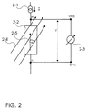
- the parameter T recorded in equation (1) points out that the resistance is not insignificant from the Temperature of the GMR sensor depends. Typically increases increasing temperature the basic resistance during the magnetoresistive resistance decreases with temperature. Typical values for the relative temperature drift of the Basic resistance R0 (T) are about 0.05% / K to 0.2% / K and for the relative temperature drift of the magnetoresistive resistor ⁇ R (T) about -0.05% / K to -0.2% / K. This Temperature dependency causes an angle assignment a measured resistance is not clear if the Temperature varies and is unknown.
- the layers of the GMR sensors are typically only a few nm thick and are made using precision techniques, e.g. Sputtering process applied to small substrates.
- the Structures of the GMR sensors are made using lithographic Methods applied to a substrate, so that several GMR sensors applied to the substrate in a small space can be.
- the electrical connections between the GMR sensors are often designed in meandering to defined Resistance on the leads to the GMR sensors too produce.
- FIG. 3a shows the two GMR sensors 3-2 and 3-3 with anti-parallel internal orientation and the current source 3-1 with the set current I 1 , which flows through the points P3, P2 and P2 to the current sink 3-6.
- the external magnetic field 3-4 acting on the GMR sensors forms the angle ⁇ with the internal magnetic orientation of the GMR sensor 3-2.
- the external magnetic field should be the same for both GMR sensors, which is easily fulfilled if the spatial extent of the two GMR sensors together is small compared to the spatial structure of the external magnetic field 3-4.
- the use of two connected in series anti-parallel GMR sensors can thus be used to by forming the difference, the large occurring in Fig. 2 (and temperature-dependent) voltage offset R0 (T) too eliminate.
- the difference can be easily Realized by analog electronic circuits so that time delays, through digitization and digital bills occurred, did not occur.
- FIG. 3a In order to eliminate the ambiguity of the angle determination in the 360 degree range, it is advisable to control a second circuit of the type shown in FIG. 3a in parallel with the same current source.
- a second circuit is shown in Fig. 3b.
- Such electronic circuits with GMR sensors for measuring the orientation of a magnetic field can be found, for example, in the publication DE 19619801 A1.
- the second circuit has GMR sensors 3-10 and 3-11 of the same type as the first circuit with the difference that the internal orientations of the two GMR sensors are largely perpendicular to the internal orientations of the GMR sensors of the first circuit , Both circuits must be close enough that they see essentially the same external 3-4 magnetic field.
- the current source 3-12 generates the current I 2 , which flows through the points P3 ', P2' and P1 'to the current sink 3-13.
- a circuit In order to ensure uniqueness in the entire 360 degree angle determination, a circuit must also be used which uses V1, V2, V1 'and V2' to decide whether the angle is in the range between- ⁇ / 2 ⁇ ⁇ + ⁇ / 2 or in the range - ⁇ ⁇ ⁇ - ⁇ / 2 or + ⁇ / 2 ⁇ ⁇ + ⁇ .
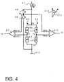
- the orientation of the external magnetic field 4-14 forms with the orientation of the internal magnetic field of the first GMR sensor 4-4 of the first sensor subcircuit 4-2 the angle ⁇ .
- Both sensor subcircuits are supplied by the same current source 4-1. Since the four GMR sensors have essentially the same resistance parameters, the current is divided equally between the two sensor subcircuits.
- a disadvantage of the relationship given in (6) and (9) is, however, that the arctan is not calculated by simple analog circuit can be accomplished. Also an approximate linearization is only in a small one Range of values possible. The calculation therefore generally requires digitization of the two output signals with one subsequent calculation of the arctan. The digitization of however, both values is both costly as time-consuming. The digital calculation of the arctan also makes programming is required because this function is in common microcontroller circuits is not implemented. This also leads to delays. Finally, the tangent infinities in the range of values with a Computers are difficult to use.
- the invention is therefore based on the object To provide a method that addresses the problems described especially the temperature dependent drift, which the Output signals of the two connected in series experienced anti-parallel GMR sensor pairs, in simple and quickly eliminated or at least reduced.
- the Another object of the invention is a system with GMR sensors to determine the orientation of a external magnetic field to provide the Temperature drift of the output signals of the two in series switched anti-parallel GMR sensor pairs on simple and quick way out.
- the inventive method makes it possible to Orientation of an external magnetic field caused by the Angle ⁇ is given with the help of four GMR sensors determine, the result of the scaling is temperature independent and when calculating on the No use of arctan and / or arccotan functions can be.
- the use of arctan and / or arccotan functions to calculate the angle ⁇ requires a Digitization of the measured values and makes the use of programmed microprocessors required what is expensive and computationally intensive.
- the invention On the other hand, the procedure only makes the calculation of one Scaling factor required, which prefers the Square root of the sum of squares from V1 and V2, respectively There are approximations to this square root. Continue to be by the inventive method negative effects of Large number of copies of the GMR sensors involved compensated.
- Scaling with the scaling factor can be preferred can be realized with analog circuits.
- the advantage of analog processing of the measured values lies in the simplicity and in the superior speed with which the measured values be processed because time delays caused by the Analog / digital conversion bypassed and the computing time through digital signal processing is avoided.
- the orientation of an external magnetic field is by the angle ⁇ between the direction of the outer magnetic field and the orientation of the sensor circuit given.
- the orientation of the sensor circuit is, by definitionem, hereinafter by the internal orientation of the given first sensor subcircuit, the internal Orientation of the first sensor subcircuit through the internal magnetic orientation of the first GMR sensor defined is.
- the orientation of the sensor circuit can in principle also be defined by another GMR sensor what that The method according to the invention changes only insignificantly. It is only adding a at the end of a measurement Angle constant to the measured value required.
- the external magnetic field, its orientation too minimum strength should preferably be determined so that the GMR sensor responds. On the other Side, the magnetic strength must not be too great, so the internal magnetic orientation in each working GMR sensor is not lost goes.
- Typical values for fields using GMR sensors can be measured in the range of 5-10 kA / m. There the GMR sensors only parallel to magnetic field components sensitive to the GMR layer levels, this relates Field strength specification on the field components in this level.
- the spatial structure of the outer magnetic field is preferably larger than the range in which houses the four GMR sensors. So is ensures that the four GMR sensors largely do that see same magnetic external field and the Output voltages V1 and V2 can be scaled exactly.
- GMR sensors for the Sensor circuit come into question.
- the inventive method is that the GMR sensors each a (hard) internal magnetic field with a fixed have embossed magnetic orientation, the Dependence of the GMR sensor resistance on the direction of the external magnetic field largely through the equation (1) must be described.
- the parameters R0 (T) are preferred and ⁇ R (T) of the GMR sensors installed in the sensor circuit the same or at least very similar so that the Temperature dependence through the inventive method can be compensated for as completely as possible.
- the GMR sensors of a circuit of the same type and preferably applied to a common substrate so the course of the parameters R0 (T) and ⁇ R (T) and the prevailing temperature T for all GMR sensors if possible are the same.
- It is also an advantage if the GMR sensors as small and close together as possible so that the Overall expansion of the GMR sensor area is small and the As a result, GMR sensors use the same outer ones if possible see magnetic field strengths.
- the sensor circuit preferably has two Sensor subcircuits with at least two GMR sensors each on. But more than two are also conceivable Sensor subcircuits for e.g. redundant measurements.
- a Sensor subcircuit each has at least a first and a second GMR sensor in series with each other are switched and each have a largely anti-parallel have internal magnetic orientation to each other.
- a Sensor subcircuit can also do more than the two have GMR sensors oriented antiparallel to each other. e.g. Each GMR sensor can be connected to one another by two or more parallel oriented GMR sensors can be replaced.
- the first and second differential circuits each generate from the three sensor voltages V (P1), V (P2) and V (P3) first and second partial sensor voltage a differential voltage V1 and V2. Because the internal orientation of the first Sensor subcircuit largely perpendicular to the internal one Orientation of the second sensor subcircuit is generated first differential circuit a differential voltage V1, which in essentially the cosine portions of the orientation of the outer magnetic field while the second Differential circuit generates a differential voltage V2, which in essentially the sine portions of the orientation of the outer represents magnetic field.
- the vertical internal Orientation of the two sensor subcircuits to one another thus enables the inventive calculation of the Scaling factors. Under vertical is to be understood that the angle between the internal orientations of the first Sensor subcircuit and the second sensor subcircuit can be both about 90 degrees and about 270 degrees.
- the differential voltages V1 and / or V2 are preferred led to a scaling circuit, preferably with a scaling factor for both values and thus scaling V1 and V2. From the two scaled V1 and V2 values can change the orientation of the outer magnetic field can be determined independent of temperature.
- a precise detection of the orientation of the outer magnetic fields using two inventive Sensor subcircuits also depend on the constancy of the Ratio of the currents through the two Sensor subcircuits from.
- the flow through the are preferred first sensor subcircuit and the current through the second Sensor subcircuit largely the same. That way the cos and sin parts of the orientation of the outer magnetic field weighted equally, so that at the same Differential circuits correctly scaled can be.
- the equality of the currents is thereby preferred realizes that both sensor subcircuits are the same Have resistance coefficients R0 (T) and ⁇ R (T) and both Sensor subcircuits through a common power source or Power source are supplied so that even with varying Temperature due to Ohm's law the currents of both Sensor subcircuits are the same.
- the scaling factor is preferred by the Square root calculated from the sum of squares V1 and V2. This is the value with which V1 and / or V2 must be scaled, by the orientation angle ⁇ des regardless of temperature external magnetic field. To be favoured both V1 and V2 are scaled to cover the entire 360 degrees To be able to clearly determine range ⁇ .
- the calculation of the scaling factor is preferably carried out by an analog circuit, since this avoids time delays and costs due to the digitization of the V1 and V2 values. This also eliminates the digital computing time for calculating the root from the sum of squares of V1 and V2.
- the quadrature of the V1 and V2 values is preferably first carried out in parallel by means of two analog multiplier circuits. In a further circuit, the sum of the two squared values is preferably generated analogously. Finally, the root of the sum of squares of V1 and V2 is also preferably generated analogously.
- the root operation can preferably also be digital be carried out what is faster and despite digitization with less effort (programmed microprocessor etc.) than the digitization and calculation of the arctan or arccotan functions as in processes according to the prior art Technique for calculating the orientation of an exterior magnetic field is carried out.
- the scaling of the V1 and / or V2 values is preferred by dividing the V1 and / or V2 values by the calculated scaling factor performed.
- the division is preferably done in an analog way to avoid time delays during digitization and switching effort save.
- the division is unproblematic in particular by the fact that the scaling factor is always greater than 0.
- the orientation angle of the external magnetic field, ⁇ can be determined from the scaled V1 and / or V2 values in various ways.
- each V1 and / or V2 value an angle ⁇ assigns.
- This table can be a calibration measurement be removed or preferably also a one-off Calculation. Because the scaled V1 and V2 values are temperature-independent, only one table is used for one Temperature needed.
- Differential switching and scaling circuit enables one easy detection and calculation of the orientation of a external magnetic field, the calculation being complete or can be carried out largely analogously.
- the simplicity of the temperature compensated calculation the orientation of an external magnetic field is based on the magnetically anti-parallel arrangement of the GMR sensors in the respective sensor subcircuits and the magnetic vertical arrangement of the sensor subcircuits to each other.
- the simplicity of the temperature compensated calculation is based continue on the constancy of the ratio of the currents that flow through the two sensor subcircuits.
- Prefers are the current through the first sensor subcircuit and the Current through the second sensor subcircuit the same.
- Prefers are both streams from a common power source drawn, the total resistance of the first Sensor subcircuit and the second sensor subcircuit are largely the same.
- the first and the second are preferred Differential circuit is the same, especially when the currents are the same through both sensor subcircuits.
- the scaling circuit preferably has a circuit to calculate the scaling factor, with the Circuit for calculating the scaling factor prefers the Square root calculated from the sum of squares of V1 and V2. This calculation is preferably carried out analogously, i.e. preferably from a circuit that only squares V1 and V2 forms, these squares are then added and the sum the square root takes.
- the root function can be preferred also by a linear and / or quadratic approximation be performed.
- the scaling circuit preferably also has one Circuit for scaling the V1 and / or V2 values. This scaling is preferably carried out by an analog one Processing, the V1 and / or V2 each by the calculated scaling factor divided.
- the scaling circuit preferably also has one Circuit on which the assignment of the scaled V1 and / or V2 values for an orientation angle of the outer magnetic field. This assignment happens preferably by tabular assignment, which is analog and / or can be done digitally. This can preferably Mapping can also be integrated into an ASIC.
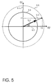
- FIG. 5 is a schematic representation of an embodiment of the method according to the invention for determining the orientation of an external magnetic field, in which the temperature dependence of the measurement can be eliminated by scaling with the scaling factor SQRT (V1 2 + V2 2 ) and thus the angle of an external one independent of temperature magnetic field can be measured without the arctan and / or arccot functions having to be tried.
- a vector V m (V1, V2) is drawn in the orthogonal coordinate system with the V1 axis 5-1 and V2 axis 5-2, the vector components V1 and V2 being the measured values from a sensor circuit as shown in FIG. 4 is shown.
- the dotted circle 5-5 represents all the points (V1, V2) that the sensor circuit according to the invention can achieve at a fixed temperature T1 by varying the orientation of an external magnetic field.
- V m (V1, V2), which lies on the unit circle 5-6:
- All vectors (V1, V2) can be created using this method project onto the unit circle so that a table with an assignment of (V1, V2) unit circle vectors to the Angle ⁇ is sufficient for each (V1, V2) vector also at unknown temperature an angle for the outside to be able to assign a magnetic field.
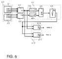
- Fig. 6 shows schematically the structure of a Execution of the electronic circuit according to the invention with GMR sensors for determining the angle ⁇ for the Orientation of an external magnetic field.
- the sensor circuit 6-0 with the two sensor sub-circuits 6-1 and 6-2, the sensor circuit 6-0 preferably one Structure as in Fig. 4 has.
- the one shown in Fig. 4 Sensor circuit is particularly characterized by the antiparallel internal magnetic orientation of the first and second GMR sensors within a sensor subcircuit as well as the vertical magnetic orientation of the two Sensor subcircuits to each other.
- the four GMR sensors preferably largely the same Basic resistance R0 (T) and the same magnetoresistive Resistance ⁇ R (T) as well as the same temperature dependence of the two parameters.
- the current is preferably through the first sensor subcircuit 4-2 is the same size as the current through the second sensor subcircuit 4-3. The power is on finally in the current sink 4-12 again.
- V1 and V2 are further processed by the embodiment of the electrical scaling circuit 6-5 shown in FIG. 6: V1 and V2 are first squared in parallel in the analog circuits for squaring 6-6 and 6-7 and the squared values in an analog Totalizers 6-8 total. Then the root is drawn from the sum of squares in a circuit for pulling the square root 6-9.
- the circuit for pulling the square root 6-9 is preferably an analog circuit.
- the output signal of the circuit for calculating the scaling factor is the scaling factor SQRT (V1 2 + V2 2 ), which is fed into the two dividers 6-10.
- the scaled values are therefore independent of temperature. The angle ⁇ can be clearly determined from them.
Landscapes
- Physics & Mathematics (AREA)
- Chemical & Material Sciences (AREA)
- Engineering & Computer Science (AREA)
- Nanotechnology (AREA)
- Condensed Matter Physics & Semiconductors (AREA)
- General Physics & Mathematics (AREA)
- Crystallography & Structural Chemistry (AREA)
- Measuring Magnetic Variables (AREA)
Abstract
Description
- Fig. 1
- Schematischer Aufbau eines GMR-Sensors nach Stand der Technik.
- Fig. 2
- Grundschaltung mit einem GMR-Sensor zur Messung der Orientierung eines äußeren magnetischen Feldes nach Stand der Technik.
- Fig. 3a - 3b
- Sensorteilschaltungen mit je zwei GMR-Sensoren für die Sensorschaltung nach Stand der Technik.
- Fig. 4
- Sensorschaltung mit GMR-Sensoren und Differenzschaltung zur Bestimmung der Orientierung eines äußeren magnetischen Feldes nach Stand der Technik.
- Fig. 5
- Mathematische Darstellung des erfindungsgemäßen Verfahrens zur Bestimmung der Orientierung eines äußeren magnetischen Feldes.
- Fig. 7
- Erfindungsgemäße Ausführung der elektronischen Schaltung mit GMR-Sensoren zur Bestimmung der Orientierung eines äußeren magnetischen Feldes.
Claims (20)
- Verfahren zur Bestimmung der Orientierung eines äußeren magnetischen Feldes mit GMR-Sensoren mit den folgenden Schritten:a) eine Sensorschaltung mit mindestens einer ersten und einer zweiten Sensorteilschaltung, die parallel zueinander geschaltet sind, wird bereitgestellt, wobei die erste und die zweite Sensorteilschaltung je mindestens einen ersten und einen zweiten GMR-Sensor aufweisen, die in Reihe geschaltet sind und die jeweils in entgegengesetzter interner magnetischer Orientierung angeordnet sind, wobei die interne magnetische Orientierung der GMR-Sensoren der ersten Sensorteilschaltung im wesentlichen senkrecht zur internen magnetischen Orientierung der GMR-Sensoren der zweiten Sensorteilschaltung ist;b) in der ersten und der zweiten Sensorteilschaltung werden jeweils drei Sensorspannungen V(P1), V(P2), V(P3) an den Punkten P1, P2 und P3 abgegriffen, wobei P1 auf der Verbindungsleitung von Stromsenke zum zweitem GMR-Sensor, P2 auf der Verbindungslinie vom zweiten GMR-Sensor zum ersten GMR-Sensor und P3 auf der Verbindungslinie von erstem GMR-Sensor zur Stromversorgung liegt;c) aus den drei Sensorspannungen der ersten Sensorteilschaltung wird durch eine erste Differenzschaltung eine Differenzspannung V1 erzeugt und aus den drei Sensorspannungen der zweiten Sensorteilschaltung wird durch eine zweite Differenzschaltung eine Differenzspannung V2 erzeugt;d) ein Skalierungsfaktor wird mit Hilfe von V1 und V2 berechnet;e) V1 und V2 werden mit dem Skalierungsfaktor so skaliert, daß aus ihnen die Orientierung des äußeren magnetischen Feldes bestimmt werden kann.
- Verfahren nach Anspruch 1,
dadurch gekennzeichnet, daß
der Strom durch die erste Sensorteilschaltung und der Strom durch die zweite Sensorteilschaltung im wesentlichen gleich sind. - Verfahren nach einem der vorhergehenden Ansprüche,
dadurch gekennzeichnet, daß
die erste Differenzschaltung und die zweite Differenzschaltung gleich sind. - Verfahren nach einem der vorhergehenden Ansprüche,
dadurch gekennzeichnet, daß
der Skalierungsfaktor die Wurzel der Quadratsummen von V1 und V2 oder eine Näherung dazu ist. - Verfahren nach einem der vorhergehenden Ansprüche,
dadurch gekennzeichnet, daß
die Berechnung der Quadrate von V1 und/oder V2 durch eine analoge Schaltung durchgeführt wird. - Verfahren nach einem der vorhergehenden Ansprüche,
dadurch gekennzeichnet, daß
die Berechnung der Quadratsumme von V1 und V2 durch eine analoge Schaltung durchgeführt wird. - Verfahren nach einem der vorhergehenden Ansprüche,
dadurch gekennzeichnet, daß
die Berechnung der Wurzel der Quadratsumme von V1 und V2 durch eine analoge Schaltung genähert wird. - Verfahren nach einem der vorhergehenden Ansprüche,
dadurch gekennzeichnet, daß
die Skalierung der V1 und/oder V2 Werte durch Division der V1 und V2 Werte mit dem Skalierungsfaktor erfolgt. - Verfahren nach einem der vorhergehenden Ansprüche,
dadurch gekennzeichnet, daß
den skalierten V1- und/oder V2-Werten Orientierungswinkel des äußeren magnetischen Feldes zuordnet sind. - System mit GMR-Sensoren zur Bestimmung der Orientierung eines äußeren magnetischen Feldes
dadurch gekennzeichnet, daßdas System eine Sensorschaltung mit einer ersten und einer zweiten Sensorteilschaltung aufweist, wobei die erste Sensorteilschaltung parallel zur zweiten Sensorteilspannung geschaltet ist und die erste und die zweite Sensorteilschaltung jeweils mindestens einen ersten und einen zweiten GMR-Sensor aufweisen, die in Reihe geschaltet sind und die jeweils in entgegengesetzter interner magnetischer Orientierung zueinander angeordnet sind, wobei die interne magnetische Orientierung der GMR-Sensoren der ersten Sensorteilschaltung im wesentlichen senkrecht zur internen magnetischen Orientierung der GMR-Sensoren der zweiten Sensorteilschaltung ist;die erste und die zweite Sensorschaltung je drei Meßpunkte P1, P2 und P3 aufweisen, wobei P1 auf der Verbindungsleitung zwischen Stromsenke und zweitem GMR-Sensor liegt, P2 auf der Verbindungsleitung zwischen erstem und zweitem GMR-Sensor und P3 auf der Verbindungsleitung zwischen ersten GMR-Sensor und Stromversorgung, so daß an den Meßpunkten P1, P2 und P3 die drei Sensorspannungen V(P1), V(P2) und V(P3) abgegriffen werden können;das System eine erste und eine zweite Differenzschaltung aufweist, wobei die erste Differenzschaltung aus den drei Sensorspannungen der ersten Sensorteilschaltung eine Differenzspannung V1 erzeugt, und die zweite Differenzschaltung aus den drei Sensorspannungen der zweiten Teilspannung eine Differenzspannung V2 erzeugt;das System eine Skalierungsschaltung aufweist, die die Differenzspannung V1 und die Differenzspannung V2 ausliest und so skaliert, daß aus den skalierten Werten die Orientierung des äußeren magnetischen Feldes bestimmt werden kann. - System nach Anspruch 11,
dadurch gekennzeichnet, daß
der Strom durch die erste Sensorteilschaltung und der Strom durch die zweite Sensorteilschaltung im wesentlichen gleich sind. - System nach Anspruch 11 bis 12,
dadurch gekennzeichnet, daß
die erste und die zweite Differenzschaltung im wesentlichen gleich sind. - System g nach Anspruch 11 bis 13,
dadurch gekennzeichnet, daß
die Skalierungsschaltung eine Schaltung zur Berechnung des Skalierungsfaktors aufweist. - System nach Anspruch 14,
dadurch gekennzeichnet, daß
die Schaltung zur Berechnung des Skalierungsfaktors eine Schaltung zur Berechnung der Wurzel der Quadratsumme der V1 und V2 Werte oder eine Näherung davon aufweist. - System nach Anspruch 11 bis 15,
dadurch gekennzeichnet, daß
die Skalierungsschaltung eine Schaltung zur Skalierung der V1 und V2 Werte aufweist. - System nach Anspruch 16,
dadurch gekennzeichnet, daß
die Schaltung zur Skalierung der V1 und V2 Werte eine Schaltung aufweist, die die V1 und V2 Werte durch den Skalierungsfaktor dividiert. - System nach Anspruch 11 bis 17,
dadurch gekennzeichnet, daß
die elektronische Schaltung einen Algorithmus und/oder Daten aufweist, die den skalierten V1 und/oder V2 Werten einen Winkel zur Bestimmung der Orientierung des äußeren magnetischen Feldes zuordnet. - System nach Anspruch 11 bis 18,
dadurch gekennzeichnet, daß
die Skalierungsschaltung eine Schaltung aufweist, die die Zuordnung eines skalierten V1, V2 Wertepaars zu einem Orientierungswinkel des äußeren magnetischen Feldes durchführt. - System nach Anspruch 11 bis 19,
dadurch gekennzeichnet, daß mindestens eine der Schaltungen der Skalierungsschaltung in einem ASIC integriert ist. - System nach Anspruch 11 bis 20,
dadurch gekennzeichnet, daß
die Spannungen V1 und/oder V2 vor elektronisch verstärkt werden.
Priority Applications (4)
| Application Number | Priority Date | Filing Date | Title |
|---|---|---|---|
| EP00114447A EP1178326B1 (de) | 2000-07-05 | 2000-07-05 | Verfahren und System zur Bestimmung der Orientierung von Magnetfeldern mit GMR-Sensoren |
| DE50011912T DE50011912D1 (de) | 2000-07-05 | 2000-07-05 | Verfahren und System zur Bestimmung der Orientierung von Magnetfeldern mit GMR-Sensoren |
| US10/332,190 US6882146B2 (en) | 2000-07-05 | 2001-06-25 | Method and system for determining the orientation of magnetic fields by means of GMR sensors |
| PCT/EP2001/007221 WO2002003089A1 (de) | 2000-07-05 | 2001-06-25 | Verfahren und system zur bestimmung der orientierung von magnetfeldern mit gmr-sensoren |
Applications Claiming Priority (1)
| Application Number | Priority Date | Filing Date | Title |
|---|---|---|---|
| EP00114447A EP1178326B1 (de) | 2000-07-05 | 2000-07-05 | Verfahren und System zur Bestimmung der Orientierung von Magnetfeldern mit GMR-Sensoren |
Publications (2)
| Publication Number | Publication Date |
|---|---|
| EP1178326A1 true EP1178326A1 (de) | 2002-02-06 |
| EP1178326B1 EP1178326B1 (de) | 2005-12-21 |
Family
ID=8169175
Family Applications (1)
| Application Number | Title | Priority Date | Filing Date |
|---|---|---|---|
| EP00114447A Expired - Lifetime EP1178326B1 (de) | 2000-07-05 | 2000-07-05 | Verfahren und System zur Bestimmung der Orientierung von Magnetfeldern mit GMR-Sensoren |
Country Status (4)
| Country | Link |
|---|---|
| US (1) | US6882146B2 (de) |
| EP (1) | EP1178326B1 (de) |
| DE (1) | DE50011912D1 (de) |
| WO (1) | WO2002003089A1 (de) |
Families Citing this family (21)
| Publication number | Priority date | Publication date | Assignee | Title |
|---|---|---|---|---|
| WO2004001341A1 (de) * | 2002-06-24 | 2003-12-31 | Ebm-Papst St. Georgen Gmbh & Co. Kg | Temperaturkompensation einer sensoranordnung (gmr) mit beidseitigen potentialänderungen |
| FR2894535B1 (fr) | 2005-12-09 | 2009-07-03 | Holophane Sa Sa | Retroviseur de vehicule automobile |
| US7825656B2 (en) * | 2007-05-30 | 2010-11-02 | Infineon Technologies Ag | Temperature compensation for spaced apart sensors |
| US7839141B2 (en) * | 2007-08-14 | 2010-11-23 | Infineon Technologies Ag | Method of biasing a magneto resistive sensor element |
| US20090066465A1 (en) * | 2007-09-06 | 2009-03-12 | Udo Ausserlechner | Magnetic core for testing magnetic sensors |
| US7923987B2 (en) | 2007-10-08 | 2011-04-12 | Infineon Technologies Ag | Magnetic sensor integrated circuit with test conductor |
| JP2009122057A (ja) * | 2007-11-19 | 2009-06-04 | Canon Inc | 計測装置 |
| US8559139B2 (en) | 2007-12-14 | 2013-10-15 | Intel Mobile Communications GmbH | Sensor module and method for manufacturing a sensor module |
| US8080993B2 (en) * | 2008-03-27 | 2011-12-20 | Infineon Technologies Ag | Sensor module with mold encapsulation for applying a bias magnetic field |
| EP2406649B1 (de) * | 2009-03-10 | 2015-09-16 | The Board of Trustees of The Leland Stanford Junior University | Temperatur- und driftkompensation in magnetoresistiven sensoren |
| US9372241B2 (en) * | 2009-11-06 | 2016-06-21 | Headway Technologies, Inc. | Multi-directional pin anneal of MR sensors with plasmon heating |
| US9817085B2 (en) * | 2012-03-15 | 2017-11-14 | Infineon Technologies Ag | Frequency doubling of xMR signals |
| US10338261B2 (en) | 2015-09-16 | 2019-07-02 | Raytheon Company | Measurement of magnetic field gradients |
| US10378900B2 (en) * | 2015-09-16 | 2019-08-13 | Raytheon Company | Magnetic field gradient navigation aid |
| US10589074B2 (en) | 2016-06-30 | 2020-03-17 | Integra Lifesciences Switzerland Sàrl | Magneto-resistive sensor tool set for hydrocephalus valve |
| US10286196B2 (en) | 2016-06-30 | 2019-05-14 | Integra Lifesciences Switzerland Sàrl | Device to control magnetic rotor of a programmable hydrocephalus valve |
| US10994108B2 (en) | 2017-09-19 | 2021-05-04 | Integra LifeSciences Switzerland Sárl | Programmable drainage valve with fixed reference magnet for determining direction of flow operable with analog or digital compass toolsets |
| US10850080B2 (en) | 2017-09-19 | 2020-12-01 | Integra LifeSciences Switzerland Sárl | Electronic toolset to locate, read, adjust, and confirm adjustment in an implantable bodily fluid drainage system without recalibrating following adjustment |
| US10850081B2 (en) | 2017-09-19 | 2020-12-01 | Integra LifeSciences Switzerland Sáarl | Implantable bodily fluid drainage valve with magnetic field resistance engagement confirmation |
| US10888692B2 (en) | 2017-09-19 | 2021-01-12 | Integra Lifesciences Switzerland Sàrl | Electronic toolset for use with multiple generations of implantable programmable valves with or without orientation functionality based on a fixed reference magnet |
| US20250323653A1 (en) * | 2024-04-16 | 2025-10-16 | Infineon Technologies Austria Ag | Self-calibrating delay line flash adc and tracking circuitry |
Citations (3)
| Publication number | Priority date | Publication date | Assignee | Title |
|---|---|---|---|---|
| US5394029A (en) * | 1993-02-17 | 1995-02-28 | Gay; John C. | Geomagnetic orientation sensor, means, and system |
| DE19613402A1 (de) * | 1996-04-03 | 1997-10-09 | Siemens Ag | Stromkompensierter Magnetfeldsensor und Verwendung desselben in einem Drehwinkelsensor |
| EP0807827A2 (de) * | 1996-05-15 | 1997-11-19 | Siemens Aktiengesellschaft | Magnetfeldempfindliche Sensoreinrichtung mit mehreren GMR-Sensorelementen |
Family Cites Families (8)
| Publication number | Priority date | Publication date | Assignee | Title |
|---|---|---|---|---|
| US4492923A (en) * | 1982-06-21 | 1985-01-08 | The United States Of America As Represented By The Secretary Of The Navy | Apparatus for measuring the spatial scalar variation of a magnetic field with vector magnetic sensors on a moderately stable moving platform |
| DE3638298A1 (de) * | 1986-11-10 | 1988-05-11 | Vdo Schindling | Verfahren und vorrichtung zur bestimmung der winkelgeschwindigkeit aus zwei signalen, die jeweils eine funktion des drehwinkels sind |
| GB2246888B (en) * | 1990-07-04 | 1994-01-19 | Thorn Emi Electronics Ltd | Calculating apparatus |
| US5644851A (en) * | 1991-12-20 | 1997-07-08 | Blank; Rodney K. | Compensation system for electronic compass |
| US5519318A (en) * | 1992-12-28 | 1996-05-21 | The United States Of America As Represented By The Secretary Of The Navy | Triaxial magnetic heading sensing apparatus having magnetaresistors and nulling coils |
| ATE197192T1 (de) * | 1996-03-29 | 2000-11-15 | Hubertus Maschek | Feldsensor und vorrichtung sowie verwendung der vorrichtung zur messung elektrischer und/oder magnetischer felder |
| EP0855599A3 (de) * | 1997-01-24 | 2001-05-02 | Siemens Aktiengesellschaft | Elektronischer Kompass |
| EP0905523B1 (de) * | 1997-09-24 | 2004-11-10 | Infineon Technologies AG | Sensoreinrichtung zur Richtungserfassung eines äu eren Magnetfeldes mittels eines magnetoresistiven Sensorelementes |
-
2000
- 2000-07-05 EP EP00114447A patent/EP1178326B1/de not_active Expired - Lifetime
- 2000-07-05 DE DE50011912T patent/DE50011912D1/de not_active Expired - Lifetime
-
2001
- 2001-06-25 US US10/332,190 patent/US6882146B2/en not_active Expired - Lifetime
- 2001-06-25 WO PCT/EP2001/007221 patent/WO2002003089A1/de not_active Ceased
Patent Citations (3)
| Publication number | Priority date | Publication date | Assignee | Title |
|---|---|---|---|---|
| US5394029A (en) * | 1993-02-17 | 1995-02-28 | Gay; John C. | Geomagnetic orientation sensor, means, and system |
| DE19613402A1 (de) * | 1996-04-03 | 1997-10-09 | Siemens Ag | Stromkompensierter Magnetfeldsensor und Verwendung desselben in einem Drehwinkelsensor |
| EP0807827A2 (de) * | 1996-05-15 | 1997-11-19 | Siemens Aktiengesellschaft | Magnetfeldempfindliche Sensoreinrichtung mit mehreren GMR-Sensorelementen |
Also Published As
| Publication number | Publication date |
|---|---|
| EP1178326B1 (de) | 2005-12-21 |
| US20040012389A1 (en) | 2004-01-22 |
| US6882146B2 (en) | 2005-04-19 |
| DE50011912D1 (de) | 2006-01-26 |
| WO2002003089A1 (de) | 2002-01-10 |
Similar Documents
| Publication | Publication Date | Title |
|---|---|---|
| EP1178326B1 (de) | Verfahren und System zur Bestimmung der Orientierung von Magnetfeldern mit GMR-Sensoren | |
| DE102018101909B4 (de) | Winkelsensor und Winkelsensorsystem | |
| DE102005024879B4 (de) | Verfahren zum Bestimmen von Restfehler-Kompensationsparametern für einen magnetoresistiven Winkelsensor und Verfahren zum Verringern eines Restwinkelfehlers bei einem magnetoresistiven Winkelsensor | |
| DE102009050427B4 (de) | Magnetsensorsystem und Verfahren | |
| DE19732616C2 (de) | Magnetfeld-Messgerät zur Messung der Drehung eines sich drehenden Körpers | |
| DE102017125732B4 (de) | Mehrdimensionale Messung unter Verwendung von Magnetsensoren und verwandte Systeme, Verfahren und integrierte Schaltungen | |
| DE102009008265B4 (de) | Anordnung zur Messung mindestens einer Komponente eines Magnetfeldes | |
| DE102013022333B3 (de) | Sensor mit vergrößertem Dynamikumfang | |
| DE102017113861B4 (de) | Winkelsensor und Winkelsensorsystem | |
| DE102014103587B4 (de) | Magnetsensorsystem | |
| DE10342260B4 (de) | Magnetoresistiver Sensor in Form einer Halb- oder Vollbrückenschaltung | |
| DE10313642A1 (de) | Offset-reduzierter Hall-sensor | |
| DE112008002741T5 (de) | Anpassung von GMR-Sensoren in einer Brücke | |
| DE102021108750A1 (de) | Magnetsensor, magnetischer wertgeber und linsenpositionsdetektionsbauelement | |
| WO2005029106A1 (de) | Sensor für die detektion der richtung eines magnetfeldes in einer ebene | |
| WO2006136577A1 (de) | Stromsensor zur galvanisch getrennten strommessung | |
| DE102008030411A1 (de) | Integrierter Hybrid-Stromsensor | |
| DE102017111979B4 (de) | Winkelsensor, Korrekturverfahren zur Verwendung mit dem Winkelsensor und Winkelsensorsystem | |
| DE102020200177A1 (de) | Streufeldrobuster xmr-sensor mit senkrechter anisotropie | |
| DE102014103588A1 (de) | Magnetsensorsystem | |
| DE112009000497T5 (de) | Ursprungspositions-Signaldetektor | |
| DE102016111256B4 (de) | Magnetfeldgenerator, Magnetsensorsystem und Magnetsensor | |
| DE102009012896A1 (de) | Magnetsensorbauelement und -verfahren | |
| DE102018118130A1 (de) | Offset-Schätzvorrichtung und -verfahren, Korrekturvorrichtung für einen Magnetsensor, und Stromsensor | |
| EP0997701A2 (de) | Offset compensated angle measuring system |
Legal Events
| Date | Code | Title | Description |
|---|---|---|---|
| PUAI | Public reference made under article 153(3) epc to a published international application that has entered the european phase |
Free format text: ORIGINAL CODE: 0009012 |
|
| AK | Designated contracting states |
Kind code of ref document: A1 Designated state(s): AT BE CH CY DE DK ES FI FR GB GR IE IT LI LU MC NL PT SE Kind code of ref document: A1 Designated state(s): DE |
|
| AX | Request for extension of the european patent |
Free format text: AL;LT;LV;MK;RO;SI |
|
| 17P | Request for examination filed |
Effective date: 20020417 |
|
| AKX | Designation fees paid |
Free format text: DE |
|
| GRAP | Despatch of communication of intention to grant a patent |
Free format text: ORIGINAL CODE: EPIDOSNIGR1 |
|
| GRAS | Grant fee paid |
Free format text: ORIGINAL CODE: EPIDOSNIGR3 |
|
| GRAA | (expected) grant |
Free format text: ORIGINAL CODE: 0009210 |
|
| AK | Designated contracting states |
Kind code of ref document: B1 Designated state(s): DE |
|
| REF | Corresponds to: |
Ref document number: 50011912 Country of ref document: DE Date of ref document: 20060126 Kind code of ref document: P |
|
| PLBE | No opposition filed within time limit |
Free format text: ORIGINAL CODE: 0009261 |
|
| STAA | Information on the status of an ep patent application or granted ep patent |
Free format text: STATUS: NO OPPOSITION FILED WITHIN TIME LIMIT |
|
| 26N | No opposition filed |
Effective date: 20060922 |
|
| PGFP | Annual fee paid to national office [announced via postgrant information from national office to epo] |
Ref country code: DE Payment date: 20140916 Year of fee payment: 15 |
|
| REG | Reference to a national code |
Ref country code: DE Ref legal event code: R119 Ref document number: 50011912 Country of ref document: DE |
|
| PG25 | Lapsed in a contracting state [announced via postgrant information from national office to epo] |
Ref country code: DE Free format text: LAPSE BECAUSE OF NON-PAYMENT OF DUE FEES Effective date: 20160202 |